HNC-8 System Operating. Manual (Milling Machine) V2.4 Series - page 3
When a positive value is input, the tool length compensation is
increased; When a negative value is input, the tool length
compensation is reduces.
Press 「Enter」 to confirm and complete modification of tool
length compensation.
3.3.2.4 Relative actual input of tool length compensation
When the relative movement distance of tool is used as tool length
compensation, input tool length compensation using relative actual
input mode.
Press 『Tool compensation』 soft key in the level 1 menu of
machining function set to enter the sub-interface;
Press 「Direction」 or 「PgUp/PgDn」 to move the cursor to tool
length compensation of corresponding tool number;
Before input, press 『Relative clear』 soft key to clear relative
coordinate value of Z axis;
Move the tool in Z direction under jog mode, the movement
distance is displayed on the relative actual coordinates of Z axis;
Press
『 Relative actual 』 soft key to input relative actual
coordinates of Z axis to tool length compensation.
3.3.3 "Coordinate System" Sub-interface
For ease of operation, the system configures "Coordinate system" function
both under "Machining" set and "Setup" set with the same function and
operation. This section is introduced with "Coordinate system" submenu
under "Setup" set.
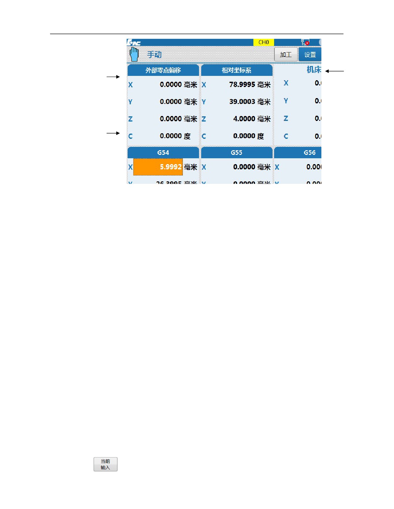
The coordinate values of "External zero offset", "Relative coordinate system",
“G54-G59 coordinate system” and "G54.1P1- G54.1P60 coordinate system"
can be set under the "Coordinate system" sub-interface (as shown below).
The coordinates of this sub-interface has 3 areas. Area 1 displays "External
zero offset" and "Relative coordinate system", area 2 displays "Machine
actual" and "Relative actual" coordinate systems, and area
3 displays
G54-G59 coordinate systems.
The coordinate value of area 2 cannot be set (the cursor cannot enter this
area). Area 1 and area 3 are switched by upper and lower cursors. The
coordinate system of current area is selected using left and right cursors or
PgUp/PgDn keys.
51
Area 2
Area 1
Area 3
3.3.3.1 Direct input of coordinate value
This function can be used to input known workpiece zero coordinates of
into the selected workpiece coordinate system.
Press 『Coordinate system』 soft key under the level 1 menu of
"Setup" function set to enter the sub-interface
Press 「Up and down cursors」 to select the coordinate system of
area 1 or 3;
Press 「Left and right cursors」 or 「PgUp/PgDn」 to select and
set coordinate system;
Press 「Enter」 to activate the input box;
Input the workpiece zero coordinate in the input box;
Press 「Enter」 to validate input, and exit the dialog box.
To abandon the input, press 「Reset」to abandon the input and exit
the input box
3.3.3.2 Current value input
After tool setting is completed and the tool moves to the workpiece
zero, this function can be used to set the machine position in the
selected coordinate system.
Press 『Coordinate system』 soft key under the level 1 menu of
"Setup" function set to enter the sub-interface
52
Press 「Cursor」 or 「PgUp/PgDn」 to move the cursor to select
the coordinate system;
Press 『Current input』 soft key to activate the input box, and a
prompt message: "Whether to set current position as the workpiece
zero " will be given
Press 「Y」 to set coordinates of current machine as the the
selected workpiece zero;
Press 「N」 or 「Reset」 to abandon setup and exit the input box.
3.3.3.3 Incremental value input
If the tool is worn or the position of coordinate system needs to be
adjusted, this function can be used for incremental input of the
coordinate zero.
Press 『Coordinate system』 soft key under the level 1 menu of
"Setup" function set to enter the sub-interface;
Press 「Cursor」 or 「PgUp/PgDn」 to move the cursor to select
the coordinate system;
Press 『Incremental』 to activate the input box;
Input the incremental value of the coordinates in the input box;
Press 「Enter」 to confirm and exit the input box;
To abandon input, press 「Reset」to invalidate the input, and exit
the input box
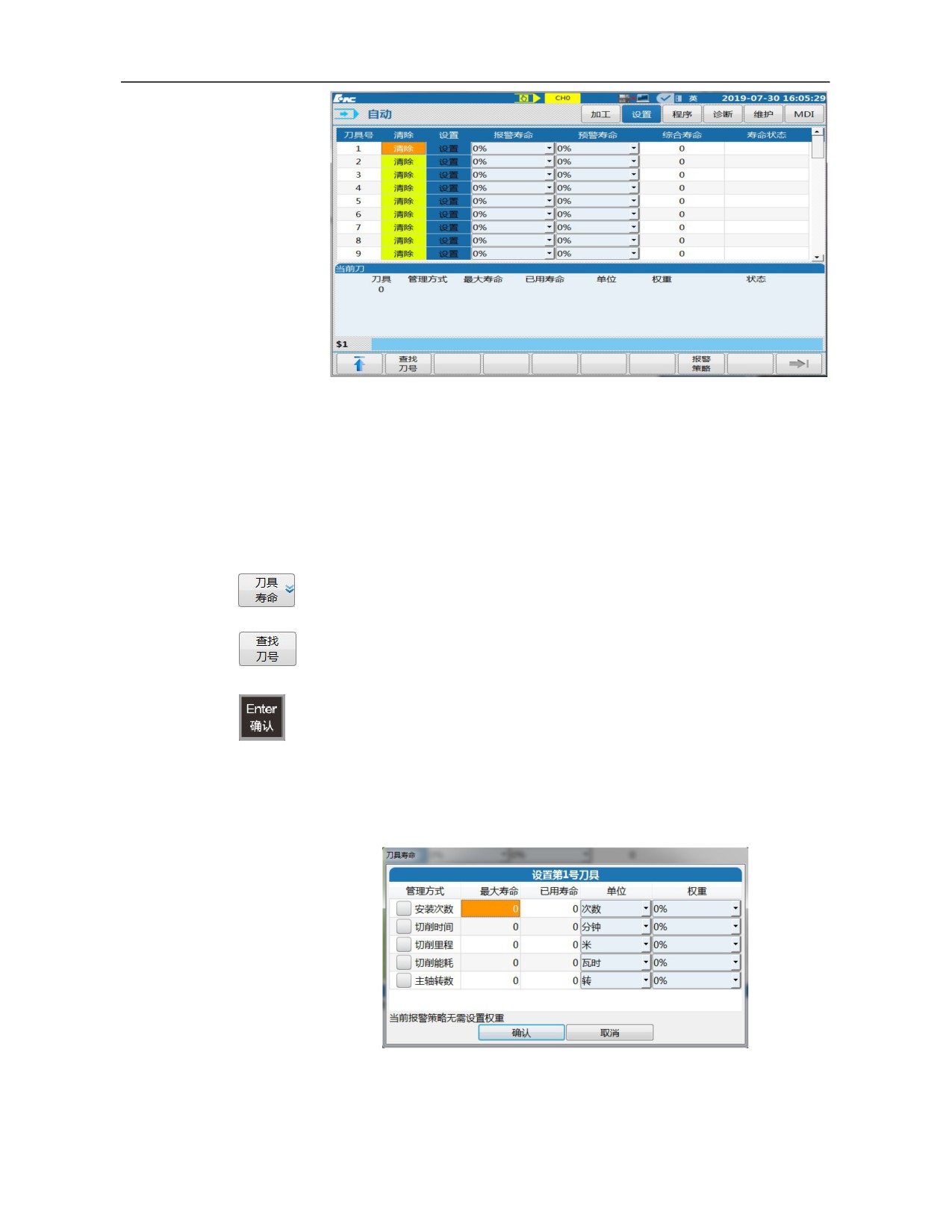
3.3.4 "Tool Life" Sub-interface
Under the "Tool life" sub-interface
(as shown below),
5 tool life
determination benchmarks can be set by "Setup": Installation times, cutting
time, cutting mileage, cutting energy consumption and spindle revolution.
When the specified value is reached for one of the benchmarks, the system
can determine tool life early warning or alarm status accordingly; The
weighted sum of the several selected benchmarks can also be used as the
basis for determining tool life. The selection of this strategy is selected by the
soft key "Alarm Strategy" under this sub-menu.
53
3.3.4.1 Tool life benchmark setup
Press『Tool life』soft key under the "setup" interface to enter the
sub-interface;
Press 「Cursor」 or 「PgUp/PgDn」 or 『Find tool number』
soft key to move the cursor to the "Setup" column of the selected
tool;
Press 「Enter」, the life benchmark setup window will pop up (as
shown below);
Select management mode, life benchmark and weight by cursor;
Press 「Enter」 to activate the input;
Press 「Enter」 to confirm the inputted values;
Select "Enter" or "Cancel" by cursor;
Press 「Enter」 to confirm and exit the setup window.
54
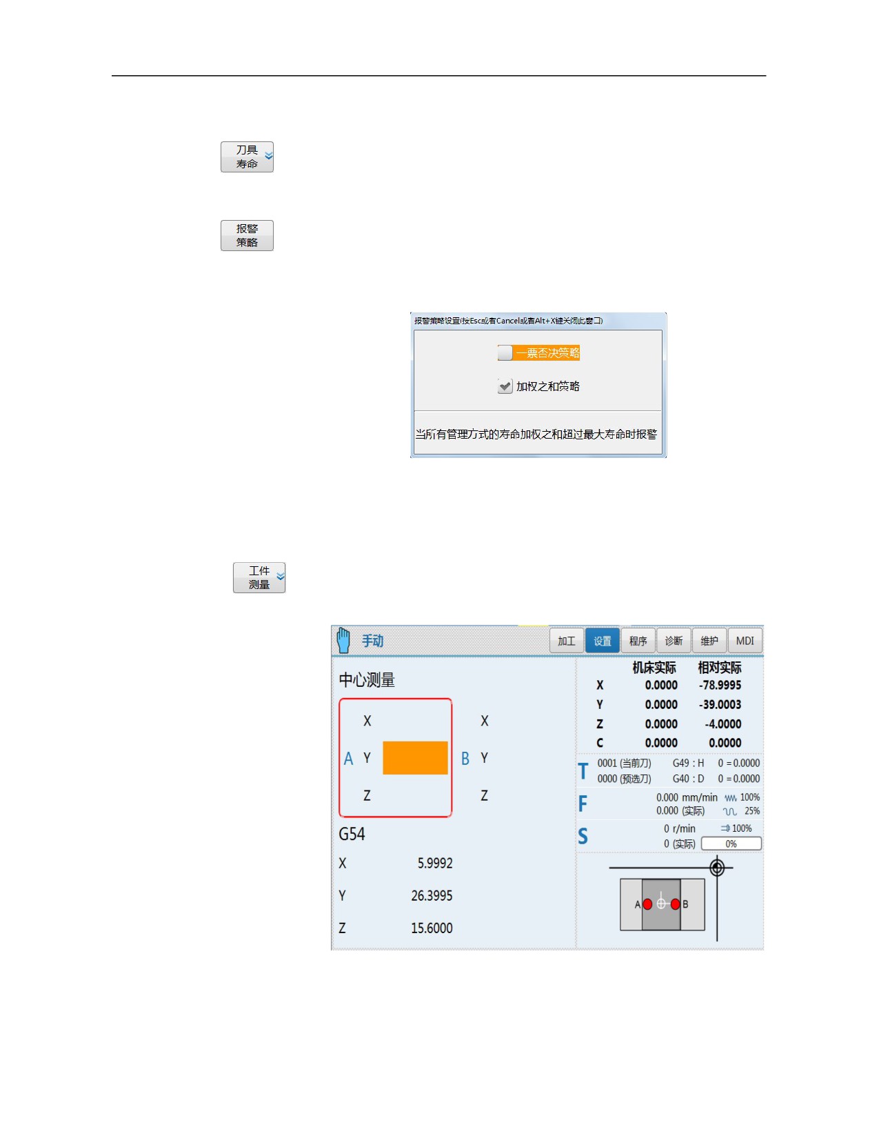
3.3.4.2 Tool life alarm strategy setup
Press『Tool life』soft key under the "setup" interface to enter the
sub-interface;
Press 『Alarm strategy』 soft key, and the strategy selection
window will pop up (as shown below)
Press 「Cursor」 to select the alarm strategy;
Press 「Enter」 to confirm and exit the selection window.
3.3.5 "Workpiece Measurement" Sub-interface
Press 『Workpiece measurement』 under the extension menu of "Setup"
function set to enter the "Workpiece measurement" default sub-interface (as
shown below), namely "Plane measurement" sub-interface.
55
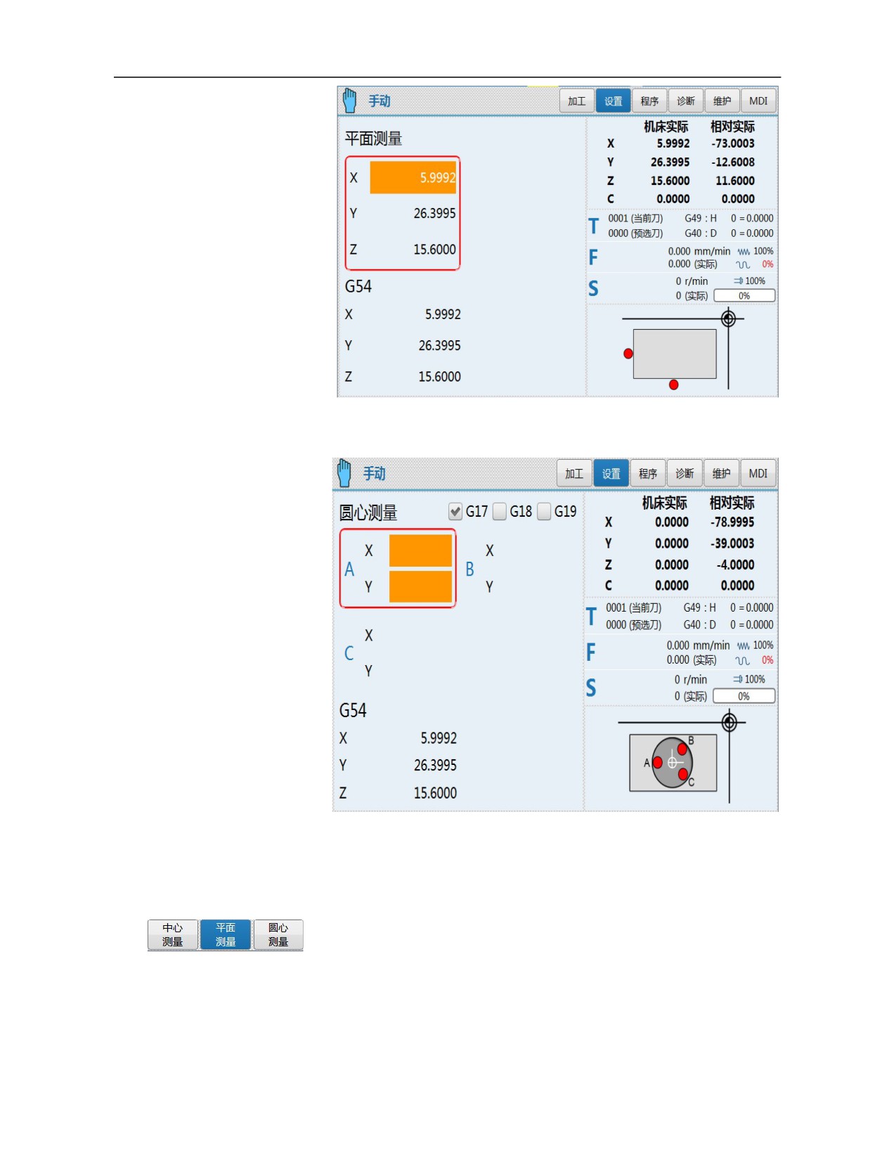
The Standard configuration supports three manual measurement functions:
center measurement, plane measurement and circle center measurement,
under the "Workpiece measurement" interface. When some appropriate
measuring instruments and softwares are configured, the plane calibration,
single point measurement, bevel edge measurement, rectangle
measurement and special-shaped circle measurement can be realized.
56
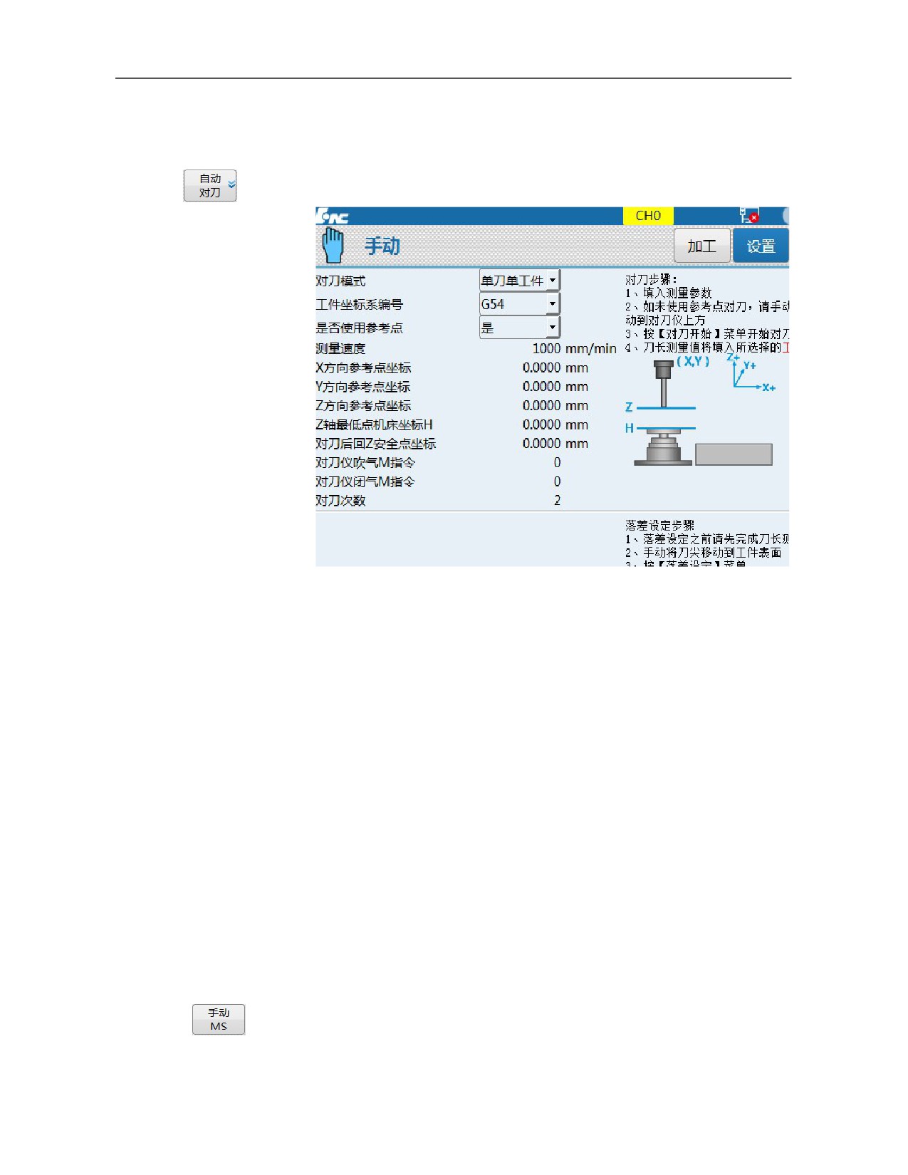
3.3.6 "Automatic Tool Setting" Sub-interface
Press 『Auto tool setting』 under the extension menu of "Setup" function
set to enter the "Auto tool setting" default sub-interface (as shown below).
The "Automatic tool setting" sub-interface supports three automatic
measurement functions of tool length including single tool single
workpiece measurement, single tool multiple workpieces measurement and
multiple tools multiple workpieces measurement. To satisfy thethree
different types of applications, the storage location of measured tool length
value is different. For single tool single workpiece measurement, the tool
length is saved in the selected workpiece coordinate system, and Z drop
value is filled in external zero offset. For single tool multiple workpieces
measurement, the tool length is saved in external zero offset, and Z drop
value is filled in the selected workpiece coordinate system. For Multiple
tools multiple workpieces measurement, the tool length value is saved in
the tool compensation table, and Z drop value is filled in the selected
workpiece coordinate system.
3.3.7 "Manual MS" Sub-interface
Press 『Manual MS』 under the extension menu of "Setup" function set to
enter the "Manual MS" setup window (as shown below).
57
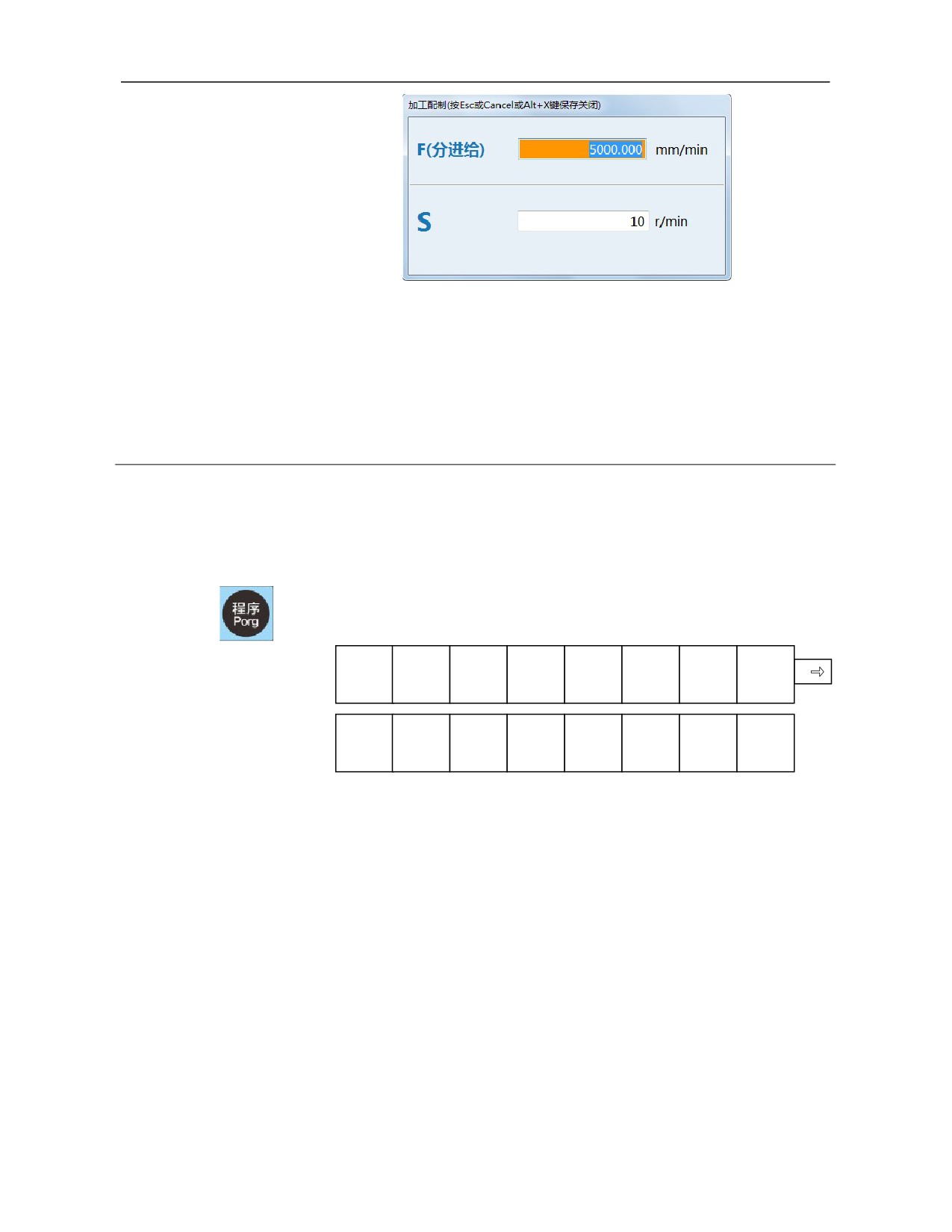
The "Manual MS" function interface supports manual definition of F/S
information. When F/S is not defined in the program, F/S value can be defined in
the interface and saved as modal. When F/S has been defined in the program, the
defined value should be saved as modal.
3.4 "Program" Function Set Interface and Basic Operation
3.4.1 "Program" Function Set Interface and Function
"Program" function set mainly integrates management function of program
file, and can create new programs. Level 1 main menu and level 1 extension
menu of soft key function of "Program" function set are shown below.
System
USB
Network
Create a
Find
Copy
Paste
Delete
Disk
flash disk
disk
new
program
Set mark
Rename
Name
Time sort
New
Writable
read only
User disk
sort
directory
System disk, USB flash disk, network disk: Source disk or target disk of
program during program file management.
New program: Create new programs with the same functions of 『New』
soft key under the 〖Machining〗 function set.
Find: Search programs in the source disk of program files.
Copy, paste: Copy programs in the source disk of program files and paste
them to the target disk.
Delete: Delete program files in the source disk.
Set mark: Mark programs in the source disk in order to copy or paste
multiple programs.
Rename: Rename programs in the source disk.
Name sort, time sort: Sort programs in the source disk of programs in
alphabetical order or modification time order in the program name.
58
New directory: Create a new program directory in the target disk of
programs.
Writable, readable: Set program files as writable or readable.
User disk: This system divides storage card (CF card) into operating
system disk area, CNC system disk area and user disk area, among which
user disk is used for backup, storage and other uses and is unrelated to
operation of machine tool.
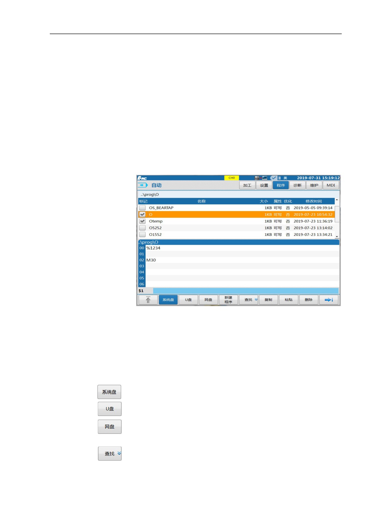
After startup, press 〖Program〗 function key to enter the default interface
of "Program" function set, as shown below.
Program can be selected under this interface. Move the cursor to file name
of the program to view the first few lines of the program for ease of
program identification.
3.4.2 Management Of Files in System Disk, USB Flash Disk and Network Disk
3.4.2.1 Management program search
Select the areas where the program searched may be located
under the "Program" default interface, namely 『System disk』,
『USB flash disk』 and 『Network disk』;
If the program to be searched is in the file directory, press
「Enter」 to open it;
Press『Find』soft key, activate the input box, prompting to input
the file to be searched;
59
Input a file name to be searched, such as O0011;
Press 『Enter』 to search corresponding program;
3.4.2.2 Program copy and paste
Press 『Find』 or 「Cursor」 and 「PgUp/PgDn」 under the
"Program" default interface to select the program to be copied
and pasted;
Press 『Copy』 soft key and the input box will give a prompt
message: Copy succeeds;
Press 『System disk』, 『USB flash disk』 and 『Network disk』
to select the target areas
If the program to be pasted is in the file directory, select the file
directory and press 「Enter」 to open it;
Press 『Paste』 soft key and the input box will give a prompt
message: Paste succeeds;
3.4.2.3 Program deletion
Press 『Find』 or 「Cursor」 and 「PgUp/PgDn」 under the
"Program" default interface to select the program to deleted;
Press 『Delete』 soft key to delete a program and a prompt
message Delete succeeds will be given.
3.4.3 Create New Programs
Press 『System disk』, 『USB flash disk』 and 『Network disk』
under the "Program" default interface to select the areas where a
new program is created;
To create new programs in the file directory, select the file
directory and press 「Enter」 to open it;
Press 『Create』 soft key and the dialog box will give a prompt
message: Input file name
Input file name, such as “OHZ1”;
Press 「Enter」 to confirm input, the working set switches from
"Program" to "Machining" and the interface switches to "Edit
program" sub-interface under the "Machining" function set.
60
After program editing is completed as stipulated, press 『Save』
soft key to save programs, and a prompt message Save succeeds
will be given.
Note 1: Both "Machining" function set and "Program" function set
have 『New』 function.
Note 2: When a new program is created under the "Machining"
function set and working mode is "Auto", "Single block" and "Jog",
the new program can be loaded automatically.
Note 3: While creating a new program under the "Program" function
set, the interface and the menu will switch to "Machining" function set
automatically, but the new program will not be loaded automatically.
3.4.4 Program Rename
Press 『System disk』, 『USB flash disk』 and 『Network disk』
under the "Program" default interface to select the areas where
the program to be renamed is located;
If the program to be renamed is in the file directory, select the
file directory and press
「Enter」 to open it;
Press 「Cursor」 or 「PgUp/PgDn」 to move the cursor to the
program to be renamed
Press 『→』 to switch to the extension menu of the "Program"
interface;
Press 『Rename』 soft key and the dialog box will give a prompt
message: Input a new file name;
Input a new file name in the dialog box, such as “OHZ2”;
Press 「Enter」 to confirm the input and the original program is
renamed as a new program.
3.4.5 Program Mark Setup
Press 『System disk』, 『USB flash disk』 and 『Network disk』
under the "Program" default interface to select the areas where
the directory or program to be marked is located;
Press 「Cursor」 or 「PgUp/PgDn」 to move the cursor to the
program to be marked;
Press 『→』 under the "Program" default interface to switch to
extension menu page of the "Program" interface;
61
Press 『Set mark』, then the program name is prefixed with “√”.
3.4.6 Programs Are Sorted By Name And Time
Press 『System disk』, 『USB flash disk』 and 『Network disk』
under the "Program" default interface to select the areas where
the program to be marked is located;
If the program to be marked is in the file directory, select the file
directory and press 「Enter」 to open it;
Press 「Cursor」 or 「PgUp/PgDn」 to move the cursor to the
program area to be sorted;
Press 『→』 under the "Program" default interface to switch to
extension menu page of the "Program" interface;
Press 『Name sort』 or 『Time sort』 soft key to sort programs
of this area as requested.
3.4.7 Program Write/Read Setup
Press 『System disk』, 『USB flash disk』 and 『Network disk』
under the "Program" default interface to select the areas where
the program to be set is located;
If the program to be set is in the file directory, select the file
directory and press 「Enter」 to open it;
Press 「Cursor」 or 「PgUp/PgDn」 to move the cursor to the
program whose attribute is set;
Press 『→』 under the "Program" default interface to switch to
extension menu page of the "Program" interface;
Press 『Write』 or 『Read only』 to set program attributes.
3.4.8 Create a New Directory
Press 『System disk』, 『USB flash disk』 and 『Network disk』
under the "Program" default interface to select the areas where
the new directory is to be created;
To create new directories in the file directory, select the file
directory and press 「Enter」 to open it;
Press 「Cursor」 to move the cursor to the areas where a new
directory is to be created;
62
Press 『→』 under the "Program" default interface to switch to
extension menu page of the "Program" interface;
Press 『New directory』 soft key and the dialog box gives a
prompt message: "Please input a directory name";
Input a directory name such as HCNC, and a new directory is
created.
3.5 "Diagnosis" Function Set Interface and Basic Operation
3.5.1
"Diagnosis" Function Set Interface And Function
"Diagnosis" function set mainly integrates such functions as fault alarm, fault
diagnosis and machine tool commissioning. Level 1 main menu and level 1
extension menu of soft key function of "Diagnosis" function set are shown
below.
Alarm
Alarm
Ladder
Display
Axis
Macro
Servo
informatio
history
status
monitor
variable
adjustmen
n
t
Self check
Log
Fault
Screw
QR
video
load
code
Alarm message: Display current alarm message
Alarm history: Save information of recent alarms and export historical
alarms to USB flash disk and user disk using "History export" soft key
in the lower menu.
Ladder: This interface is used for monitoring and editing of PLC as well
as the PLC module setting and query.
Status display: Display and view the status of all registers.
Axis monitor: Display and view status of axis, including coordinate
position, pulse value, breakpoint position, compensation value and load
current of axis.
Macro-variable: Display and view the value of macro-variables.
Servo adjustment: Optimize servo parameters to improve the
positioning and repeatability accuracy in the movement process the
response speed of machine tool, thus improving machining quality and
efficiency.
Self-check: Diagnose the change of health index during operation of
machine tool; used for detecting assembling and commissioning
63
consistency.
Log: Record all contents such as system fault diagnosis, machining
information, file modification, panel operation and system event during
operation of machine tool. This function can be regarded as the black
box of CNC system.
Fault video: Record fault related data 10s before the fault occurs. The
related data can be preset as position, speed and current of each axis.
Screw load: Record operation frequency of all areas of screw during
long-term operation of machine tool in order to determine the screw
wear and other statuses.
QR code: This function can be used to acquire data of machine tool
such as machining status, alarm history and fault diagnosis, upload
them to cloud data center and realize full life circle management of
machine tool.
Intelligent functions and interfaces such as "Servo adjustment" and
"Self-check" are not introduced in this chapter. For specific operations,
refer to the subsequent chapters.
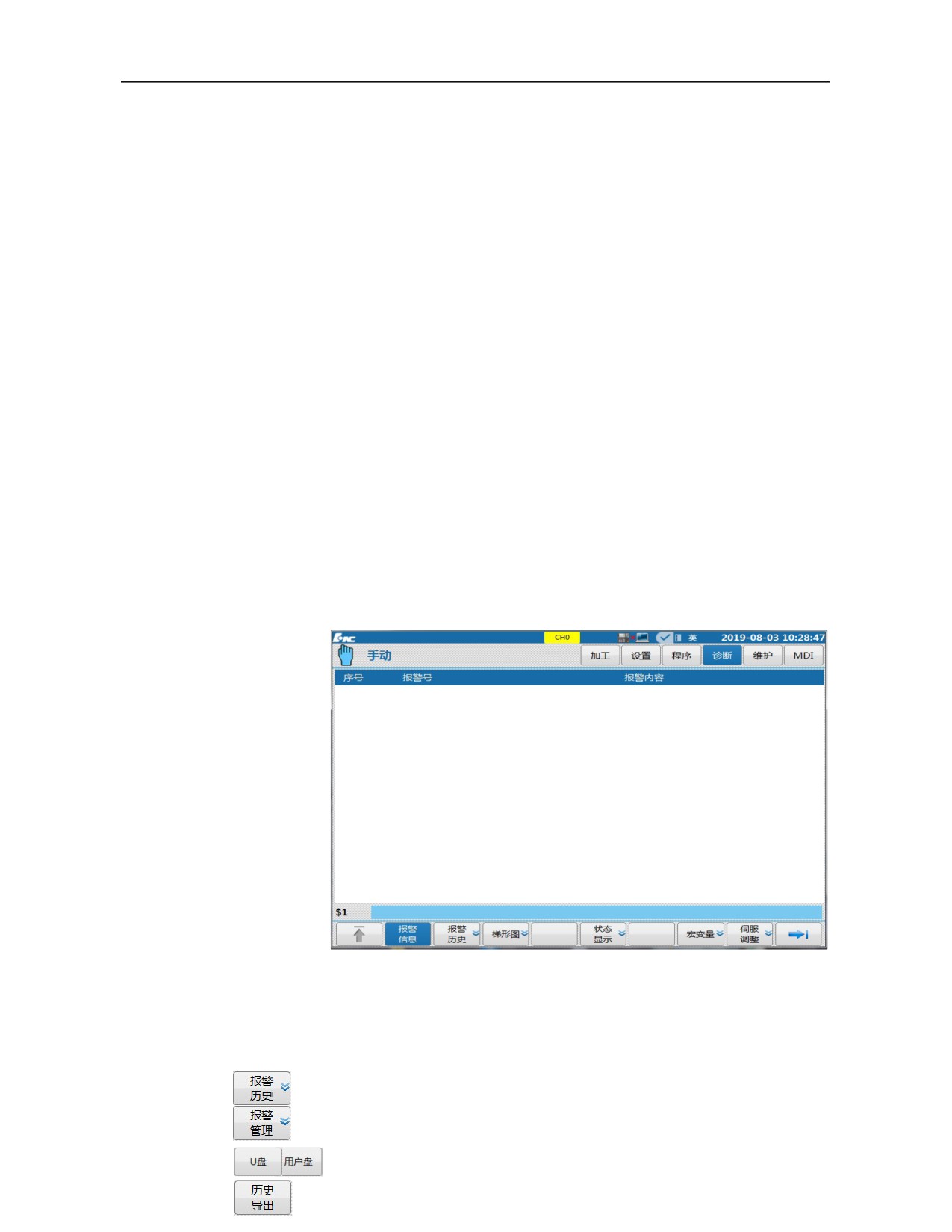
After startup, press 〖Diagnosis〗function key to enter the default interface
of "Diagnosis" function set, as shown below.
3.5.2 Alarm History Export
Press 『Alarm history』 soft key under the "Diagnosis" function
set default interface;
Press 『Alarm history』 soft key under the 『Alarm history』
64
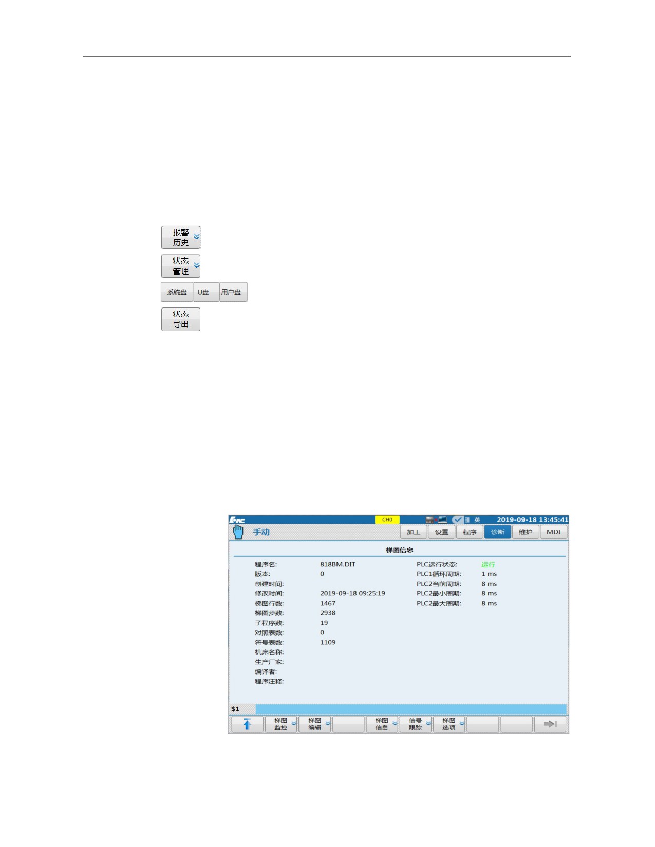
sub-interface;
Press 『Alarm manage』 soft key;
Select 『USB flash disk』 and 『User disk』 soft keys;
Press
『History export』 soft key to export corresponding
information to the selected disk.
3.5.3
Status Record Export
Press 『Alarm history』 soft key under the "Diagnosis" function
set default interface;
Press
『Status record』 soft key under the "Alarm history"
sub-interface;
Press 『Status management』 soft key;
Select 『System disk』, 『USB flash disk』 and 『User disk』
soft keys;
Press
『 Status export 』 soft key to export corresponding
information to the selected disk.
3.5.4 "Ladder " Sub-interface
This function is used for modification, monitoring and editing of system
PLC. Press 『Ladder』 soft key under the "Diagnosis" interface to enter
the ladder diagram sub-interface, as shown below.
Note: This interface requires the workshop administrator or higher
permission to enter, please refer to 3.6.5.
65
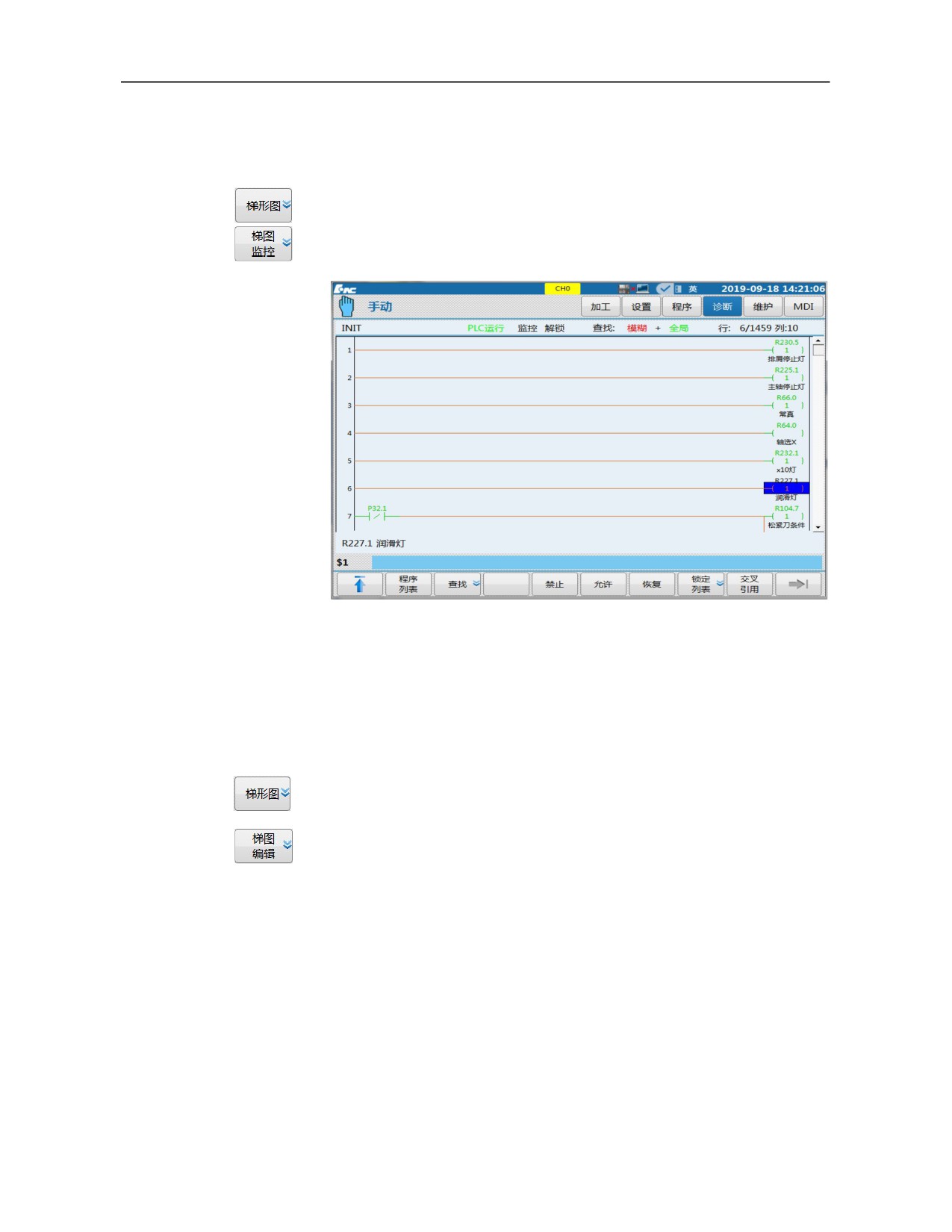
3.5.4.1 Ladder monitoring
This function is used for monitoring system PLC
Press 『Ladder』 soft key under the "Diagnosis" default interface;
Press 『Ladder monitoring』 soft key to enter the ladder diagram
monitoring sub-interface (as shown below);
3.5.4.2 Ladder diagram editing
This function is used for PLC modification
Press 『Ladder』 soft key under the "Diagnosis" interface to enter the
ladder diagram sub-interface;
Press 『Ladder editing』 soft key to enter the ladder diagram editing
interface (as shown below);
Add elements of ladder diagram using straight line, normally open,
normally closed, logic output, negation output, vertical line, function
module and double coil (see main menu and extension menu in the
below figure)
Search and edit ladder diagram using program list, delete vertical line,
search, delete element, edit network and list editing (see main menu
and extension menu in the below figure)
"Update modification" is to save modifications of ladder diagram
(see extension menu in the below figure)
"Abandon modification" is to abandon modifications of ladder
66
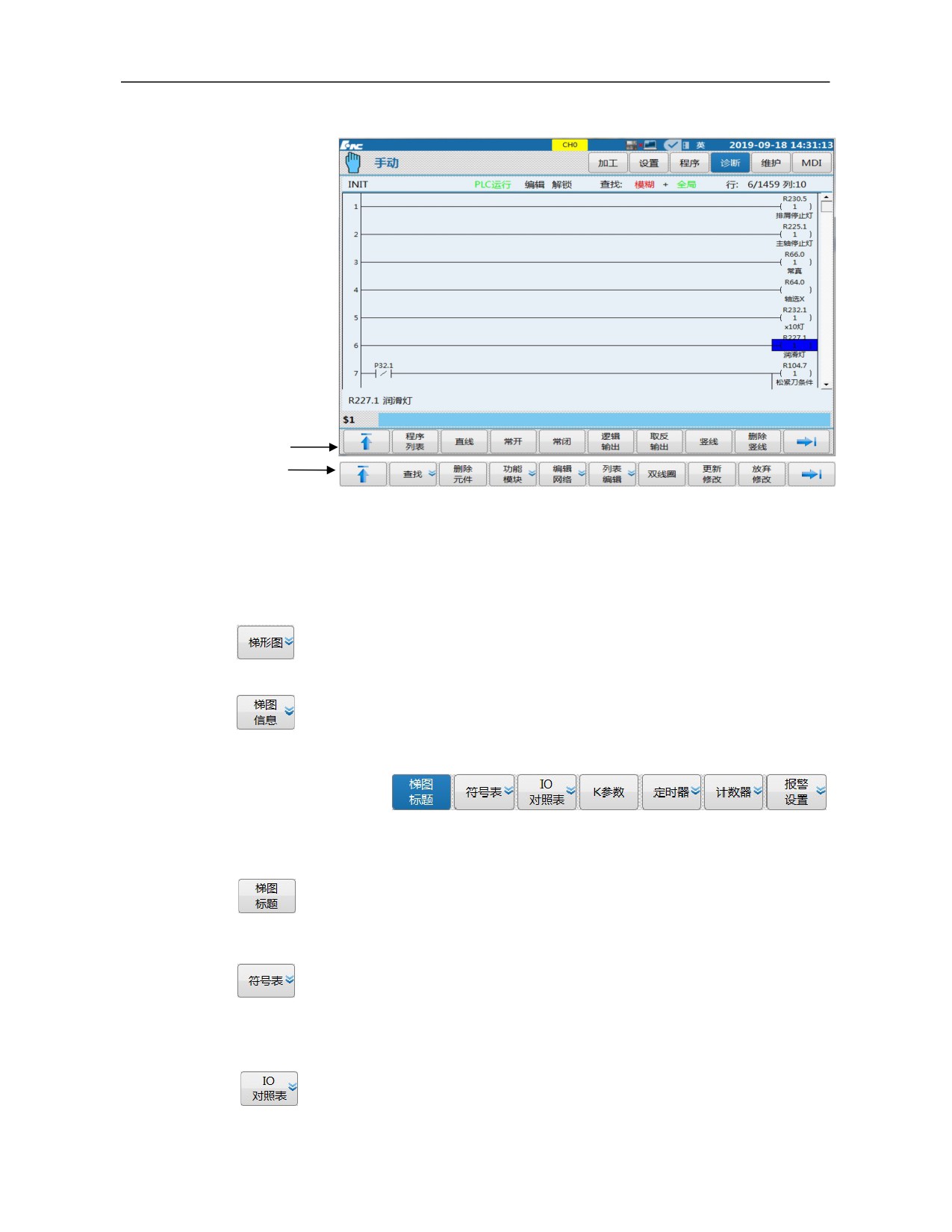
diagram (see extension menu in the below figure)
Main menu
Extension menu
3.5.4.3 Ladder diagram information
This function is mainly used to edit name and corresponding point
location of register and view related information of ladder diagram.
Press 『Ladder』 soft key under the "Diagnosis" default interface;
Press 『Ladder information』 soft key to enter the sub-interface
and the lower-level menu (as shown below).
1. Ladder diagram title
Record line number, period and program name in the related
information interface of ladder diagram
2. Symbol table
Chinese name setup table of X, Y, F, R and G registers is mainly
used to view point location information.
3. IO comparison table
Version 2.4 uses I register and Q register to replace output of X
register and Y register in PLC. In this case, if different machine
tools are configured, only a set of PLC is required to be used in
67
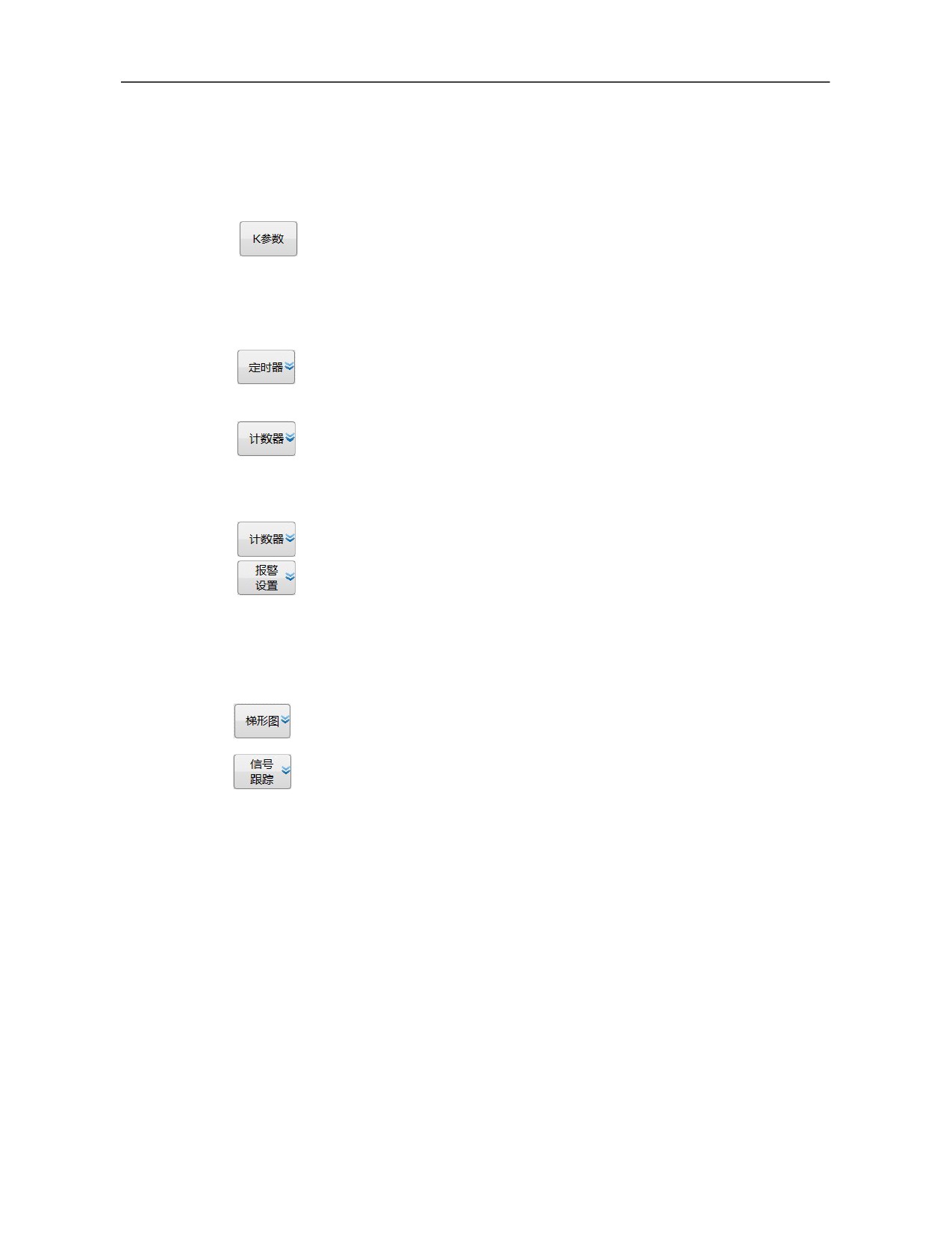
order to reduce problems of PLC. While configuring different
machine tools, PLC needs not to be modified for the change of
IO point. Different XY registers correspond to IO registers and
IO point location remains unchanged in PLC.
4. K parameter
Function and P parameter are the same, but 0 or 1 point location
can be modified directly in this interface.
5. Timer and counter
Used to monitor status of timer and counter in monitoring
program.
6. Alarm setup
Used to view alarms in PLC, namely alarms corresponding to
G3010.0-G3025.15 (alarm registers).
3.5.4.4 Ladder signal tracking
This function can be used to track the value change of registers
through sampling.
Press 『Ladder』soft key under the "Diagnosis" default interface;
Press 『Signal track』 soft key to enter the PLC signal tracking
sub-interface (as shown below);
68
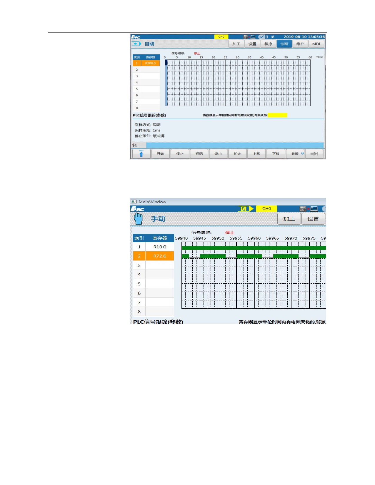
For example, sample “Run allowed R10.0”and a blinking point R72.6, fill in the
two registers in the corresponding box, click to start sampling, and the changes
of the two points will be displayed in histogram.
69
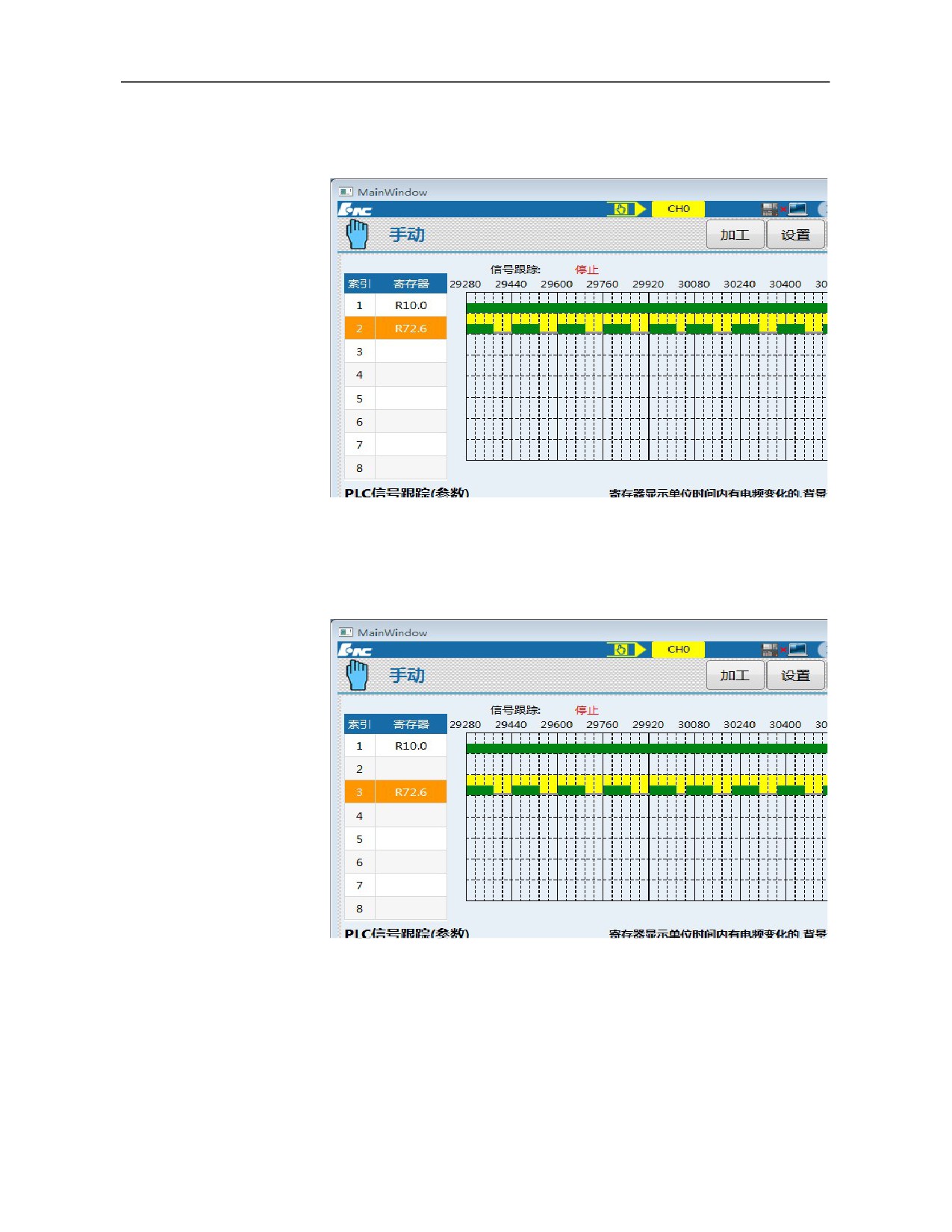
Press Zoom out and Zoom in to control the interval time between two sampling
points. For example, the figure below is a reduction of the sample of the above.
Press Move up and Move down to move the sample where the cursor is located
up or down one line. For example, move R72.6 down one line.
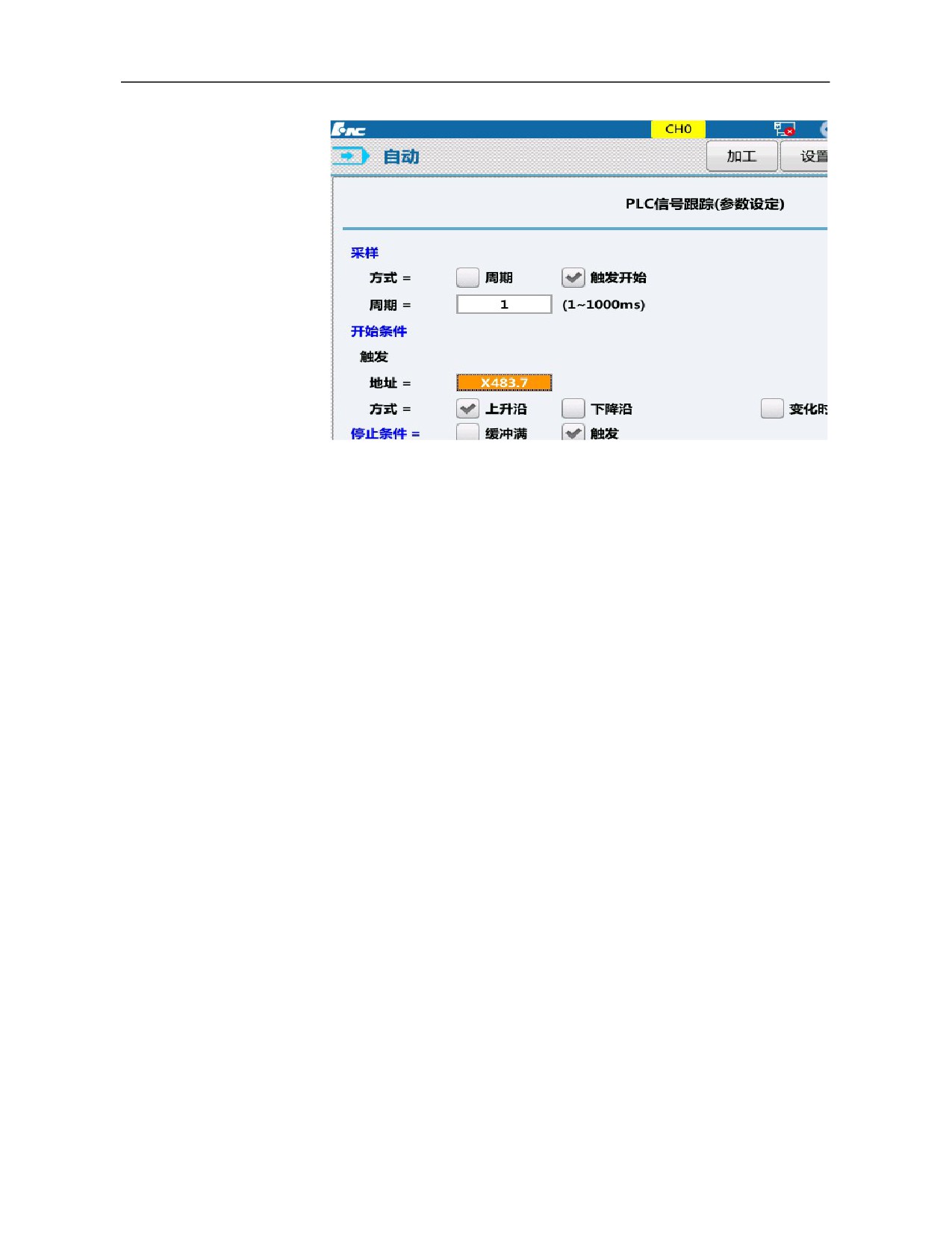
On the parameter interface, users can control the enabling conditions of
sampling function. In the above example, if the start condition is changed to
trigger start, and the trigger condition is changed to X483.7, then there will be
no sampling start after clicking to start, but pressing the X483.7 button once will
start sampling. If the stop is changed to trigger stop with the stop condition
X483.6, then the sampling can be stopped by pressing the stop button or X483.6
button.
70
3.5.5 Display of Register Status and Macro-variable Value
This function can be used to display and view status of registers and
value of macro-variable for ease of fault analysis.
Press 〖Diagnosis〗 function key to enter the default interface of
function set;
Press 『Status display』or『Macro-variable』soft key to display
status of X, Y, F, G, R and B registers or values of macro-variable
addresses;
71
3.6 "Maintain" Function Set Interface and Basic Operation
3.6.1 "Maintain" Function Set Interface and Function
Integrate such functions as parameter configuration, system commissioning
and machine tool information under "Maintain" function set. The level 1
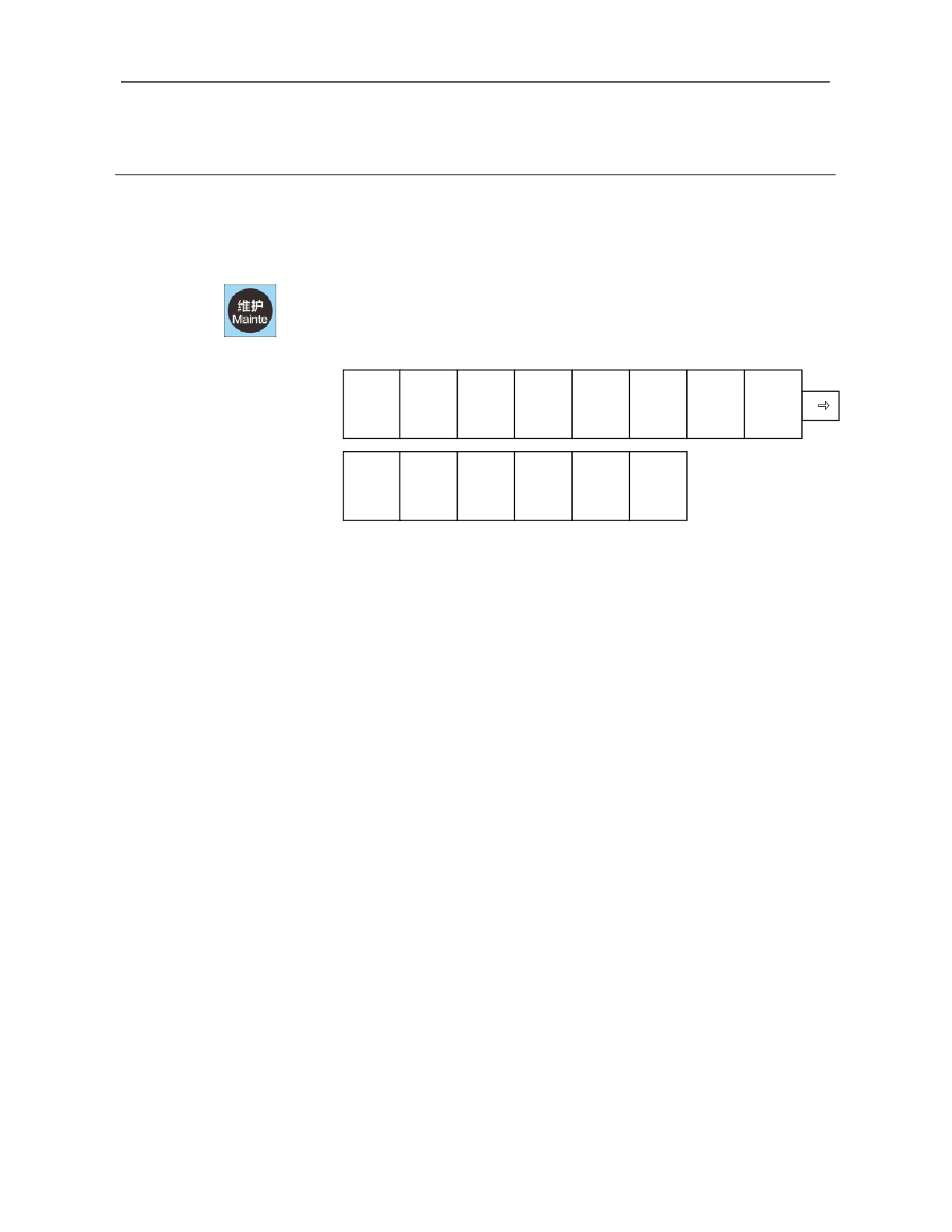
main menu and level 1 extension menu of soft key function of "Maintain"
function set are shown below.
Device
Paramete
Paramete
User set
Batch
Data
System
Permissio
configura
r set
r
manage
upgrade
n manage
tion
classifica
tion
Spatial
Time set
Process
Machine
System
Register
compens
package
informati
informati
ation
on
on
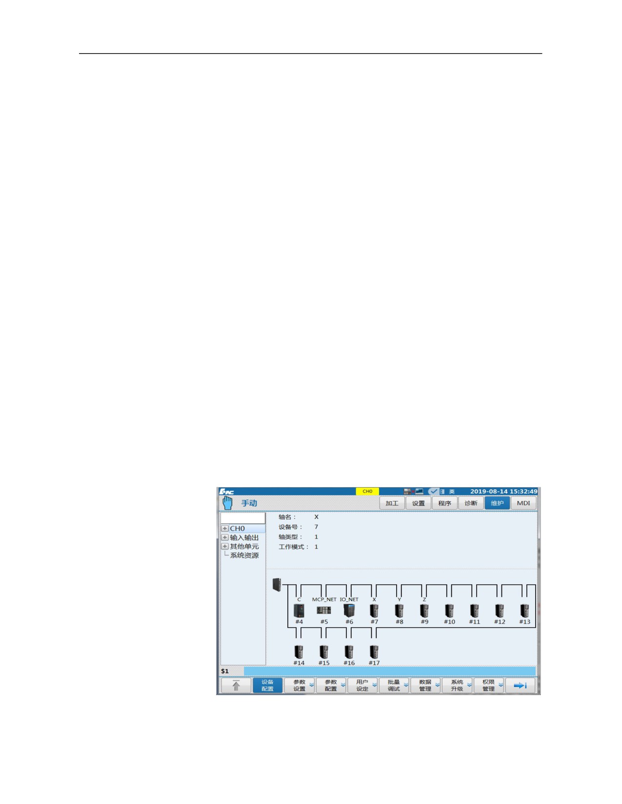
Device configuration: View number of drive, I/O, panel and other
hardware devices, and connection sequence of bus;
Parameter set: This interface includes all system parameters including NC
parameter, machine user parameter, channel parameter, coordinate axis
parameter, error compensation parameter, device interface parameter and
data table;
NC parameter: Common parameters of CNC system.
Machine user parameter: Common parameters relating to machine
tool and users.
Channel parameter: Common parameters of channels.
Axis parameter: Related parameters of logical axis (electronic gear
ratio, acceleration/deceleration time constant, and so on)
Error compensation parameter: Set related parameters of error
compensation of logical axis (such as backlash compensation type of
axis 0)
Device interface: Parameters of interface of connection between
physical device and CNC system (such as device type and device ID)
Data table: Data table storing corresponding compensation values of
error compensation parameters.
Parameter configuration: the common user parameters in this interface,
which are classified according to application type for ease of setting;
72
Parameters under this interface include user parameter, axis parameter,
pitch compensation, IO device, local spindle device, bus axis device and
function parameter;
User set: Setup relating to user application. This interface includes
display setup, P parameter, M code, PLC switch, communication setup
and personalized setup;
Batch: Loading and backup of PLC, parameter, canned cycle, G code and
other files;
Data manage: Loading and backup of various types of data;
System upgrade: System upgrade and backup;
Permission manage: To set the administrators of different permissions.
Different permissions have certain influence on the structure of interfaces
and menus;
Spatial compensation: Spatial error compensation setup;
Time set: System time setup;
Process package: Load or back up process package file;
Machine information: Edit or display machine tool information;
System information: Display information of the system;
Register: Display registration code and related information of the
machine tool;
After startup, press 〖Maintain〗 function key to enter the default interface
of "Maintain" function set, as shown below.
73
3.6.2
Parameter Setup
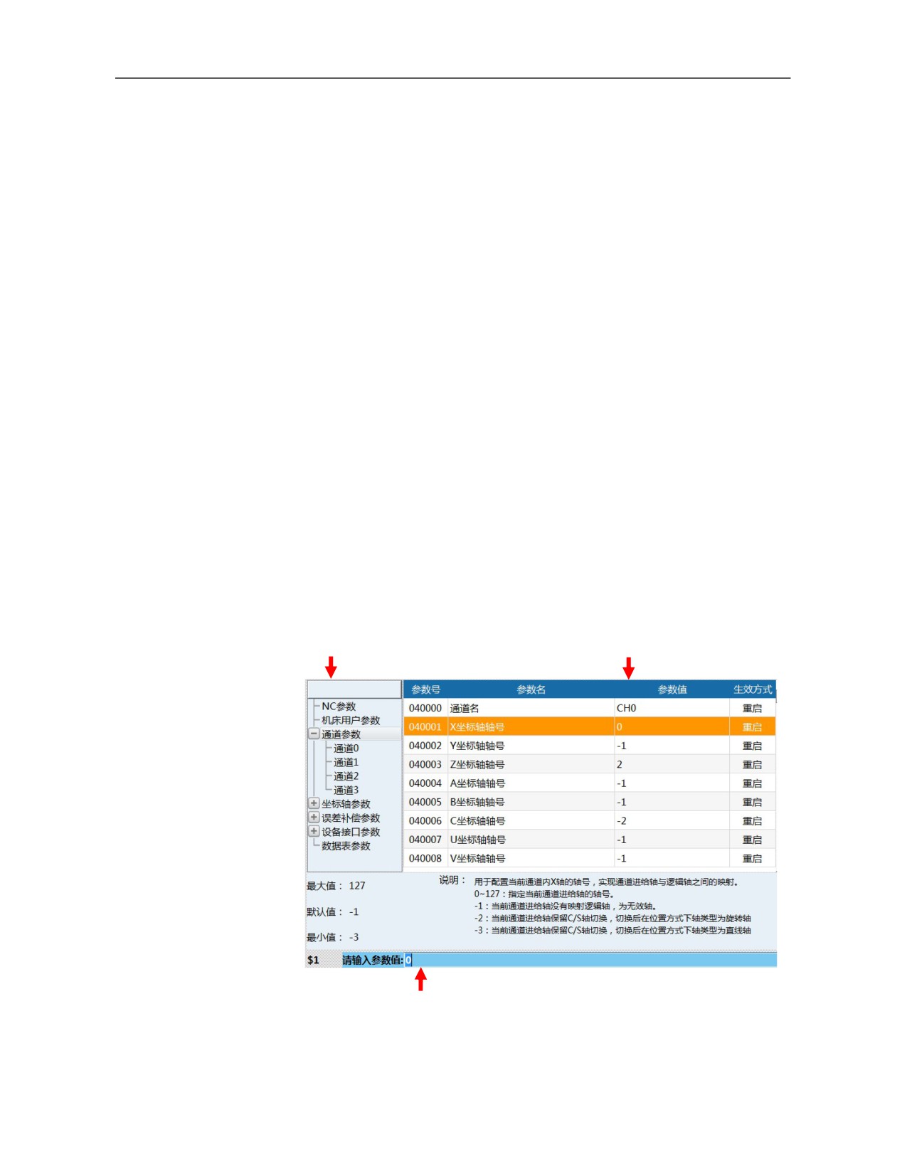
1) Parameter selection
Press 『 Device configuration 』 ,
『 Parameter classification 』 and
『Parameter set』 to select parameter set;
Press 「Left and right cursors」 to move the cursor and select parameter
lower classification column or parameter setup column
2) Parameter input activation
When the cursor moves to parameter classification column, press 「Enter」
to open categories of the selected parameter
When the cursor moves to parameter setup column, press 「Enter」 to
activate the input box
3) Parameter input
After the input box is activated and corresponding values are inputted,
press 「Enter」 to confirm the input.
4) Exit input
To abandon the input after input box is activated, press 「Reset」 to exit
the input, and the original value is maintained.
Parameter classification column
Parameter setting column
Input box
74
3.6.3
Parameter Validation and Operation
There are 5 effective types of parameters in this system: effective immediately,
effective after save, effective after reset, effective after restart, and solidified
(which cannot be set). The specific operations are as follows:
1) Immediate validation of parameters
After parameters are inputted into the input box, press 「Enter」 to
confirm, parameters are inputted successfully and take effect
immediately.
2) Save to take effect parameters
After parameters are inputted in the input box, press 「Enter」 to confirm
and a prompt message "Setup succeeds, save to take effect" will be given;
Press『Save』or『↑』soft key and the input box gives a prompt message
"Whether to save the modification? (Y/N)”;
Press 「Y」 or 「Enter」 to confirm, a prompt message "Setup succeeds"
will be given and parameters take effect;
Press 「N」 to abandon save and restore the original value.
3) Reset to take effect parameters
After parameters are inputted in the input box, press 「Enter」 to confirm
and a prompt message "Setup succeeds, reset to take effect" will be given;
Press『Save』or『↑』soft key and the input box gives a prompt message
"Whether to save the modification? (Y/N)”;
Press 「Y」 or 「Enter」 to confirm, a prompt message "Save parameters
successfully, please press Reset" will be given;
Press 「Reset」 to confirm, a prompt message "Reset succeeds" will be
given and parameters take effect;
Press 「N」 to abandon save and restore the original value.
4) Restart to take effect parameters
After parameters are inputted in the input box, press 「Enter」 to confirm
and a prompt message "Setup succeeds, reset to take effect" will be given;
Press『Save』or『↑』soft key and the input box gives a prompt message
"Whether to save the modification? (Y/N)”;
Press 「Y」 or 「Enter」 to confirm, a prompt message "Save parameters
successfully, please power off and restart" will be given;
After the system is powered off, restart it to validate parameters.
75