HNC-8 System Operating. Manual (Milling Machine) V2.4 Series - page 1
HNC-818 System Operating Manual
Introduction
Contents
Introduction
i
Introduction
vii
1
Overview
8
1.1
Basic Operation
8
1.2
Basic Function
9
1.3
Basic Display Interface
10
1.3.1
Machining Display Interface
10
1.3.2
Program Selection And Edit Interface
13
1.3.3
Machining Setup Interface
14
2
Operating Equipment
14
2.1
System Host Panel (NC Panel)
14
2.1.1
System Host Panel Zoning
14
2.1.2
Display Interface Zoning
15
2.1.3
Definition Of Host Panel Keys
16
2.1.4
Function of Keys on MDI Keyboard
17
2.2
Operation Panel of Machine Tool (MCP Panel)
20
2.2.1
Operation Panel Zoning of Machine Tool
20
2.2.2
Definition of Machine Operation Panel
21
2.3
Handheld Unit
24
3
Display Interface
26
3.1
Display Interface Selection and Menu Structure
26
3.1.1
Common Operation of Interface and Menu Selection
26
3.1.2
Function Menu Structure
27
3.2
Display Interface and Basic Operation of "Machining" Function Set
36
3.2.1
Interface and Function of "Machining" Function Set
36
3.2.1.1 Machining set interface zoning
37
3.2.1.2 Switching of graphics and G code area display
38
3.2.1.3 "Big character coordinate" display setup of coordinate graphics display area
39
3.2.1.4 "Joint coordinate" display setup of coordinate graphics display area
39
3.2.1.5 Switch of machining and commissioning information area display
39
3.2.1.6 Switching of machining information area display
39
3.2.2
"Select Program" Sub-Interface
40
3.2.2.1 Select a program in the USB flash disk and load it as current machining program .
40
3.2.2.2 Select a program in the directory as current machining program
41
3.2.2.3 Exit file directory
41
3.2.2.4 Edit current machining program in the backstage
41
3.2.2.5 Edit other programs than current machining program in the backstage
42
3.2.2.6 Edit and creates new programs in the backstage
42
3.2.3
"Program Editing" Sub-interface
43
3.2.3.1 Edit current machining program
44
ii
3.2.3.2 Create new programs
44
3.2.3.3 Block operation
44
3.2.4
"Verify" Sub-interface
45
3.2.4.1 "Verify" runs
46
3.2.4.2 Exit "Verify"
46
3.2.5
"Path setup" Sub-interface
46
3.3
"Setup" Function Set Interface and Basic Operation
47
3.3.1
"Setup" Function Set Interface and Function
47
3.3.2
"Tool Compensation" Sub-interface
49
3.3.2.1 Direct input mode of tool length compensation
50
3.3.2.2 Input mode of tool length compensation of current position
50
3.3.2.3 Incremental input of tool length compensation
50
3.3.2.4 Relative actual input of tool length compensation
51
3.3.3
"Coordinate System" Sub-interface
51
3.3.3.1 Direct input of coordinate value
52
3.3.3.2 Current value input
52
3.3.3.3 Incremental value input
53
3.3.4
"Tool Life" Sub-interface
53
3.3.4.1 Tool life benchmark setup
54
3.3.4.2 Tool life alarm strategy setup
55
3.3.5
"Workpiece Measurement" Sub-interface
55
3.3.6
"Automatic Tool Setting" Sub-interface
57
3.3.7
"Manual MS" Sub-interface
57
3.4
"Program" Function Set Interface and Basic Operation
58
3.4.1
"Program" Function Set Interface and Function
58
3.4.2
Management Of Files in System Disk, USB Flash Disk and Network Disk
59
3.4.2.1 Management program search
59
3.4.2.2 Program copy and paste
60
3.4.2.3 Program deletion
60
3.4.3
Create New Programs
60
3.4.4
Program Rename
61
3.4.5
Program Mark Setup
61
3.4.6
Programs Are Sorted By Name And Time
62
3.4.7
Program Write/Read Setup
62
3.4.8
Create a New Directory
62
3.5
"Diagnosis" Function Set Interface and Basic Operation
63
3.5.1
"Diagnosis" Function Set Interface And Function
63
3.5.2
Alarm History Export
64
3.5.3
Status Record Export
65
3.5.4
"Ladder " Sub-interface
65
3.5.4.1 Ladder monitoring
66
3.5.4.2 Ladder diagram editing
66
3.5.4.3 Ladder diagram information
67
3.5.4.4 Ladder signal tracking
68
3.5.5
Display of Register Status and Macro-variable Value
71
iii
3.6
"Maintain" Function Set Interface and Basic Operation
72
3.6.1
"Maintain" Function Set Interface and Function
72
3.6.2
Parameter Setup
74
3.6.3
Parameter Validation and Operation
75
3.6.4
"Parameter Classification" Sub-interface
76
3.6.4.1 Direct input of parameter classification value
76
3.6.4.2 Direct input of pitch error compensation value
77
3.6.5
Classification and Switching of Management Permission
77
3.6.6
System Upgrade
80
3.6.7
Data Management
81
3.6.8
User Setup
83
3.6.8.1 Display setup
83
3.6.8.2 Set "P parameter"
84
3.6.8.3 Set "M code"
85
3.6.8.4 Set "PLC switch"
88
3.6.8.5 Communication setup
89
3.6.8.6 Personalized setup
97
3.6.9
Process Package Setup
98
4
Power-on, Power-off, Safety Protection, Emergency Stop
101
4.1
Power-on
101
4.2
Power-off
101
4.3
Overtravel Protectiona And Release
102
4.3.1
Overtravel Protection
102
4.3.2
Hardware Overtravel Release
102
4.3.3
Over Travel Release
103
4.4
Emergency Stop
103
4.4.1
Feed Hold
103
4.4.2
Reset
104
4.4.3
Emergency Stop
104
5
Manual Operation and Speed Override
105
5.1
Manual Reference Point Return
105
5.2
Move Coordinate Axis By Manual Feed
106
5.3
Rapidly Move Coordinate Axis Manually
107
5.4
Move Coordinate Axis By Handwheel
108
5.5
Manual Control Of Spindle
109
5.6
Other Manual Operations
110
5.7
Speed Override
111
5.7.1
Feedrate Override
111
5.7.2
Rapid Traverse Speed Override
111
6
Program Edit and Management
113
6.1
Program Search
113
6.1.1
Machining Or Editing Program Search
113
6.1.1.1 Direct search
113
6.1.1.2 Search programs under different disks by "Find" function
114
6.1.1.3 Search programs under the directory by "Search" function
114
iv
6.1.2
Search Of Management Program (to Be Transmitted and Deleted)
115
6.1.2.1 Direct search
115
6.1.2.2 Search programs under different disks by "Search" function
116
6.1.2.3 Search programs under the directory by "Search" function
116
6.2
Program Edit
117
6.2.1
Create New Programs
117
6.2.1.1 Create new programs under "Machining" function set
117
6.2.1.2 Create new programs under "Program" function set
119
6.2.2
Modification and Editing Of Program
119
6.2.2.1 Editing and modification of current loading program
119
6.2.2.2 Editing and modification of non-loading program in the backstage
120
6.2.3
Save as
120
6.2.3.1 Save program as "Current loading program"
121
6.2.3.2 Save "Non-loading program" as
121
6.2.4
Copy and Paste of Program Block
122
6.3
Program Management
123
6.3.1
Rename of File Directory and Program
123
6.3.2
Copy and Paste File Directory and Program
124
6.3.3
Program Deletion
124
6.3.3.1 Program deletion under "Machining" function set
124
6.3.3.2 Program deletion under "Program" function set
125
7
Auto Operation
126
7.1
Auto Operation
126
7.1.1
Load Machining Program
126
7.1.1.1 Load a new program as machining program
126
7.1.1.2 Load existing programs as machining program
127
7.1.2
Program Run
127
7.1.3
Program Verify
128
7.1.4
Program Graphics Simulation
129
7.2
Automatic Operation Control
129
7.2.1
Single-block Operation
129
7.2.2
Block Skip Operation
130
7.2.3
Execute from Any Line
131
7.2.4
Stop Operation
132
7.2.5
Optional Stop
132
7.2.6
Dwell
133
7.2.7
Terminate Operation
134
7.3
MDI Operation
134
7.4
Handwheel Precutting
137
7.5
Machining Information Query
138
8
Tool Setting and Machining Setup
139
8.1
Manual Tool Setting
139
8.2
Workpiece Measurement
142
8.2.1
Center Measurement
142
8.2.2
Plane Measurement
144
v
8.2.3
Circle Center Measurement
145
8.3
Automatic Tool Setting
146
8.3.1
Single Tool Single Workpiece Measurement
147
8.3.2
Single Tool Multiple Workpiece Measurement
150
8.3.3
Multiple Tools Multiple Workpiece Measurement
153
8.4
F/S machining Setup
156
9
Machine Tool Commissioning
158
9.1
System Upgrade
158
9.1.1
System Upgrade
158
9.1.2
System Backup
159
9.2
Batch Commissioning
160
9.2.1
Batch Load Commissioning
160
9.2.2
Batch Backup Commissioning
161
9.3
Pitch Error Compensation
162
9.3.1
Generation Of Pitch Error Compensation Data File
162
9.3.2
Operation of Pitch Error Compensation Sub-interface
163
9.3.3
Import of Pitch Error Compensation Data File
164
10
Use and Maintenance Information
167
10.1
Environmental Conditions
167
10.2
Grounding
167
10.3
Power Supply
168
10.4
Dust Removal Of Filter Fan Screen
168
10.5
Use After Long-time Idle
168
vi
Introduction
Dear customer:
We feel greatly honored and express sincere gratitude to you for using our products!
This manual describes matters concerning interface and operation of HNC-8 CNC milling system in detail.
However, we cannot describe all the matters which must not be done, or which cannot be done, because there are
so many possibilities. Therefore, matters that are not especially described as possible in this manual should be
regarded as “impossible” or “not allowed”.
In order to ensure safety and normal use of the product, please thoroughly read this manual before installation or
use.
Safety warning
Improper operation will result in a safety accident, so operators must be qualified for transportation, installation,
commissioning and machining.
Copyright
Copyright of this manual should be reserved by HNC. Any units and individuals' publication or duplication should
be deemed as illegal behavior and we will hold them accountable.
vii

HNC-8 System Operating Manual (Milling Machine)
1 Overview
HNC-8 CNC milling system includes HNC-808Di-M, HNC-8Di-M,
HNC-8Ai-M, and HNC-8Bi-M. This manual is based on HNC-808Di-M
panel type. In case of discrepancies, please refer to the specification
provided by the machine tool manufacturer.
1.1
Basic Operation
HNC-808Di-M system is a CNC controller for CNC milling machine.
The MCP panel is furnished with 6 working mode keys "Jog, auto, single
block, MDI, incremental/handwheel, and reset". During operation of
CNC lathe, function description and content of these 6 working modes
are shown below.
Working mode
Functional description
Function application
Jog
Control continuous movement of
Preparation
for
parts
machine tool axis and auxiliary
machining
and
simple
action by Jog key.
machining.
Auto
The machine tool runs continuously
Continuous and automatic
and automatically based on the
machining,
program
edited program.
verification of parts.
Single block
The
machine
tool
runs
Machining position check
automatically block by block based
and program verification.
on the edited program.
MDI*
The machine tool runs the manually
Automatic machining and
inputted program.
coordinate setup of simple
parts.
Incremental/handwheel
Accurately control axis movement
Tool setting or manual
of machine tool by key or
machining of simple parts.
handwheel.
Reset
Control of the axis to return to the
Calibrate the position of
reference point.
machine tool after start.
* For the non-Di series version, the MDI working mode is configured as the MDI
function set of NC panel
8
HNC-8 System Operating Manual (Milling Machine)
1.2
Basic Function
To complete different work under different working modes,
corresponding application functions should be used. The NC panel of
HNC-808Di-M CNC device is furnished with 6 function keys "machining,
setup, program, diagnosis, maintenance and user-defined (MDI)". Every
function key corresponds to a group of function sets. User can select
corresponding functions and interfaces form the function set through
function soft keys (for soft key function menu and display interface, refer
to chapter 3 "Display interface").
Function description and main content of function sets are shown below:
Function set
Function
Function content
description
Machining
Functions of auto
1. Program editing: Edit new programs*, edit current loading
machining
programs, edit options;
2. Program machining: Machining program selection, program
verification, program machining;
3. Tool setting: Coordinate system, tool compensation setup*;
4. Interface display: Path setup, display switch;
5. Others: User macro, machining information, parameter setup
(user)*.
Setup
Functions of tool
Tool setting
(coordinate system, workpiece measurement,
setting
automatic tool setting), tool compensation setup*, tool life
management
Program
User program
Edit new program*, select, copy, paste, and delete programs from
management
system disk, USB flash disk, and network disk, program rename
function
and sort, set mark
Diagnosis
Fault diagnosis,
1. Fault diagnosis function: Alarm message, alarm history, ladder
performance
diagram, PLC status, macro-variable, log, and other functions;
commissioning,
2. Performance commissioning function: Servo adjustment
intelligent function
3. Intelligent function: QR code, fault record, and screw load check
Maintain
Hardware setup,
1. System hardware device configuration and configuration
parameter setup,
sequence setup function: Device configuration
system upgrade,
2. Setup function of common parameters: Parameter setup
basic information,
3. Setup function of user optional parameters: Parameter setup*
data management,
4.
System upgrade and commissioning function: Batch
and relevant
commissioning, data management, system upgrade, permission
maintenance
management, and user setup
functions
5.
Registration, basic information and other functions:
Registration, machine tool information, system information,
technology package, and time setup
User-defined
Functions of
Dwell, clear, save, input
** (MDI)
manual data input
9
HNC-8 System Operating Manual (Milling Machine)
Description:
* While configuring standard version function set, for ease of operation,
some identical soft key functions are configured in different function
sets (function set can be configured according to user need)
**For other series than HNC-8 Di series, user-defined key is often set as
the MDI function.
1.3 Basic Display Interface
HNC-808Di-M system can realize different application functions through
function keys and function soft keys, and display corresponding
interfaces. The display interface of this system mainly includes
machining display interface, program selection and editing interface,
machining setup interface, parameter setup interface, and fault alarm
display interface, and so on.
The operator can know the current status and information of system
through interface, or have a man-machine conversation in the
conversation area to realizecommand input, parameter setup and other
operations.
All interfaces are briefly introduced based on HNC-808Di-M standard
configuration.
1.3.1 Machining Display Interface
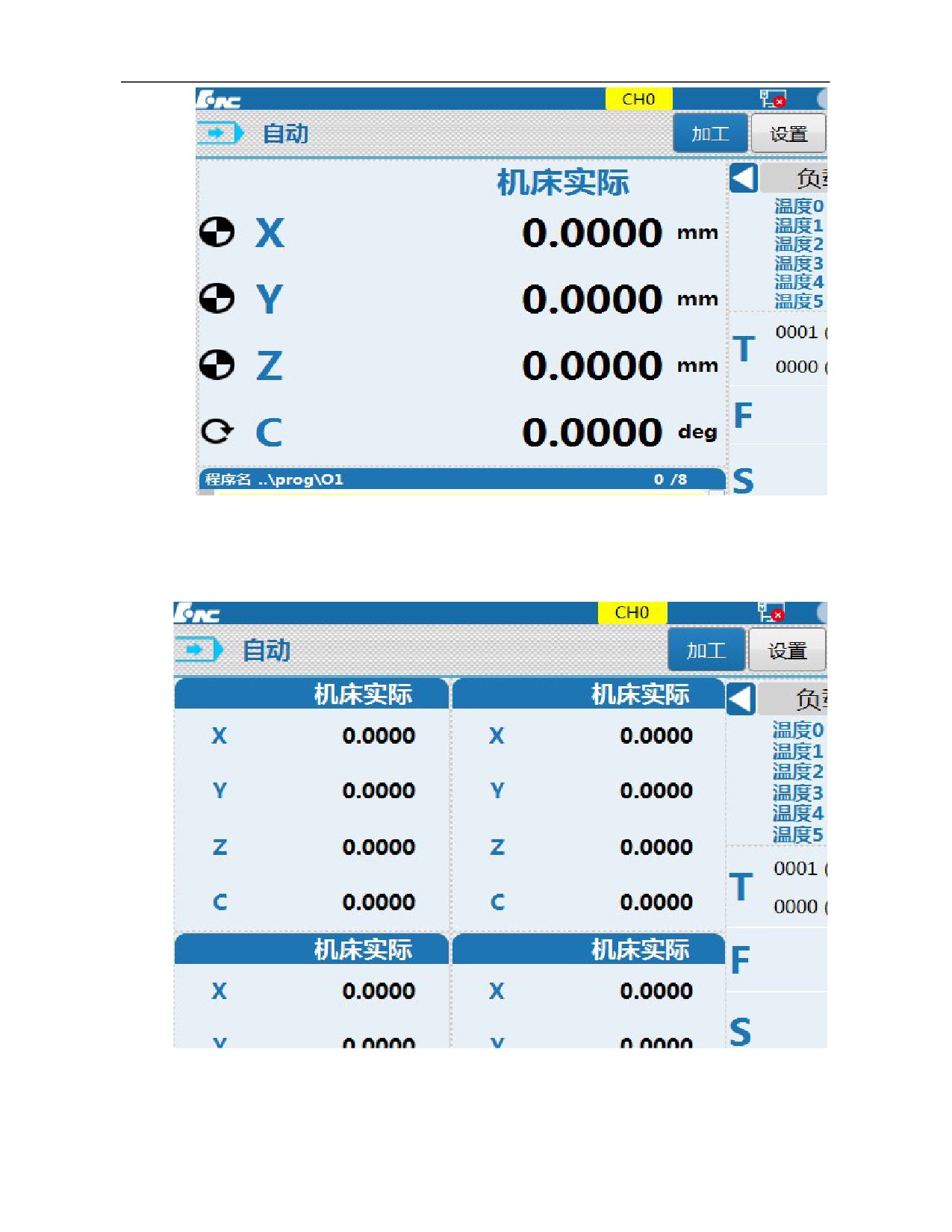
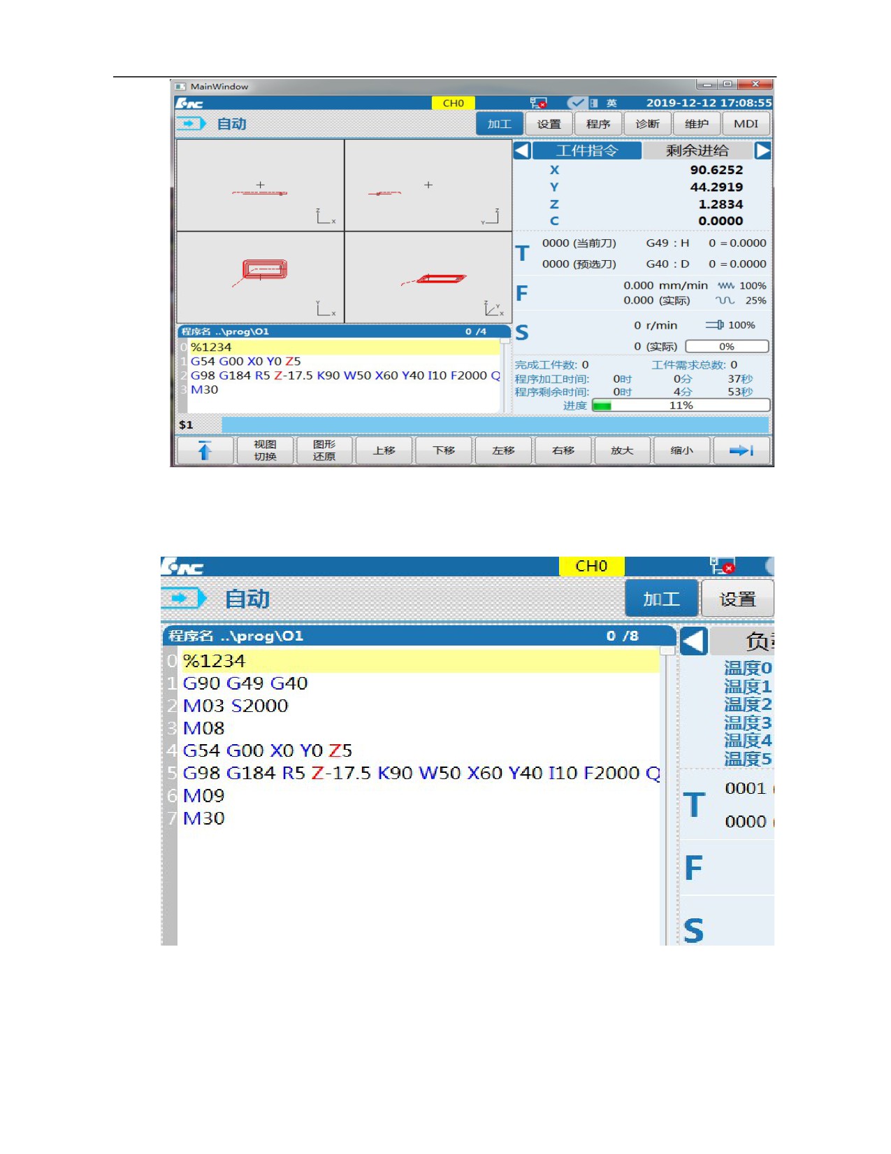
The machining display interface enables the operator to observe the
machining process and has 4 display forms: big character coordinate +
program, joint coordinate, graphics path + program, and program. These
4 interface can be switched through 『Display switch』 soft key.
10
HNC-8 System Operating Manual (Milling Machine)
Big character coordinate + program display interface
Joint coordinate display interface
11
HNC-8 System Operating Manual (Milling Machine)
Graphics path + program display interface
Program display interface
12
HNC-8 System Operating Manual (Milling Machine)
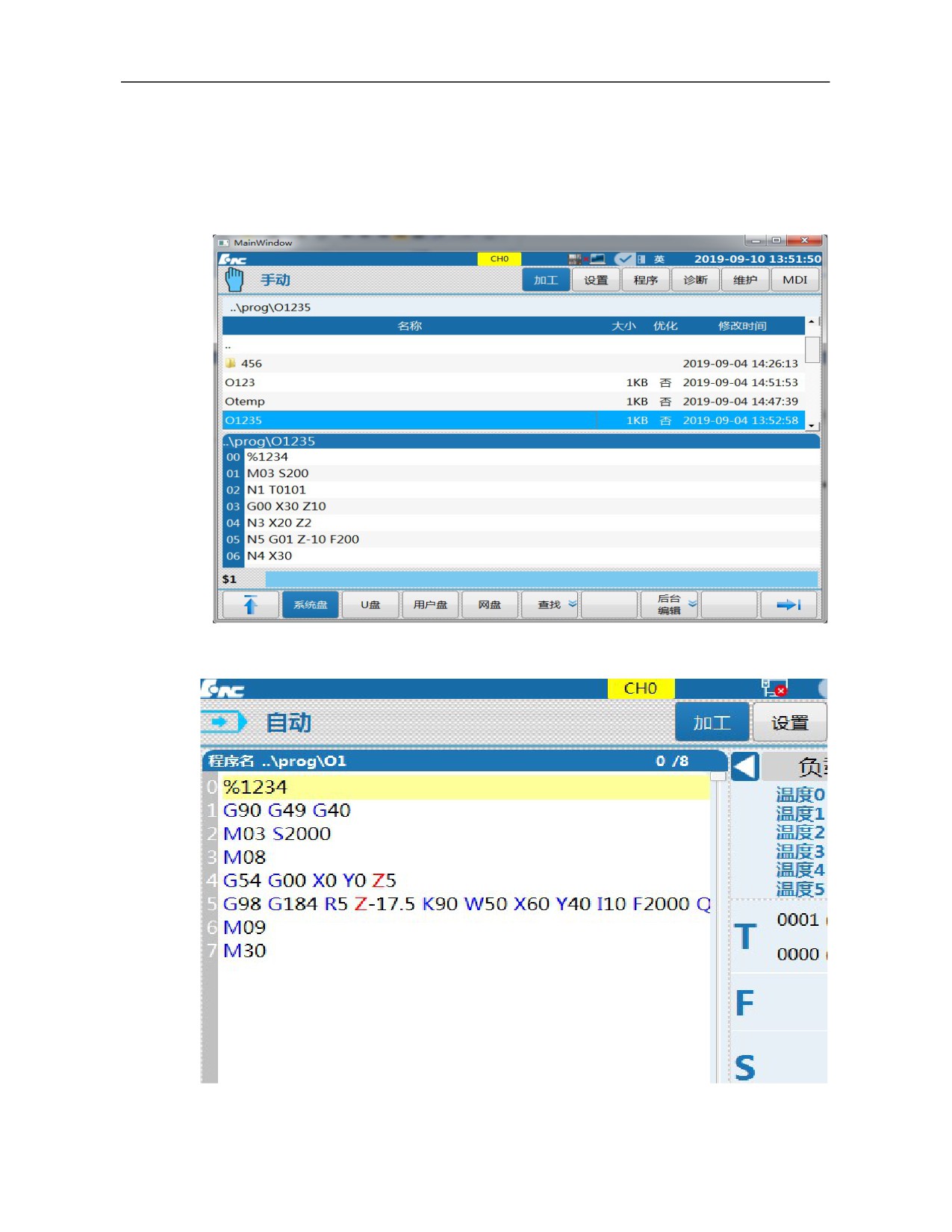
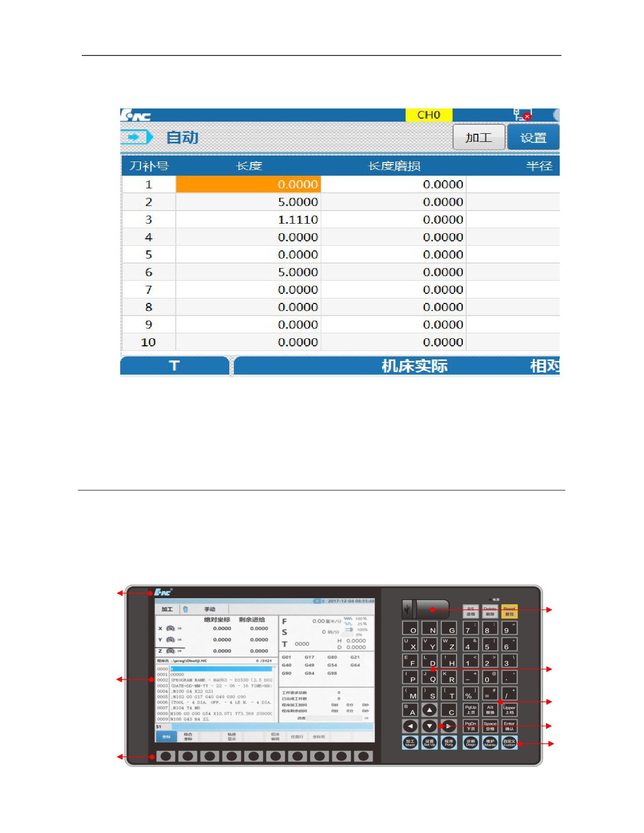
1.3.2 Program Selection And Edit Interface
This system can select programs by cursor. When the cursor selects a
program name in the list, the first blocks of the program will be displayed
in the lower part of the screen in order to confirm the programs found.
Program selection interface
Program editing interface
13
HNC-8 System Operating Manual (Milling Machine)
1.3.3 Machining Setup Interface
Machining setup interface
2 Operating Equipment
2.1 System Host Panel (NC Panel)
2.1.1 System Host Panel Zoning
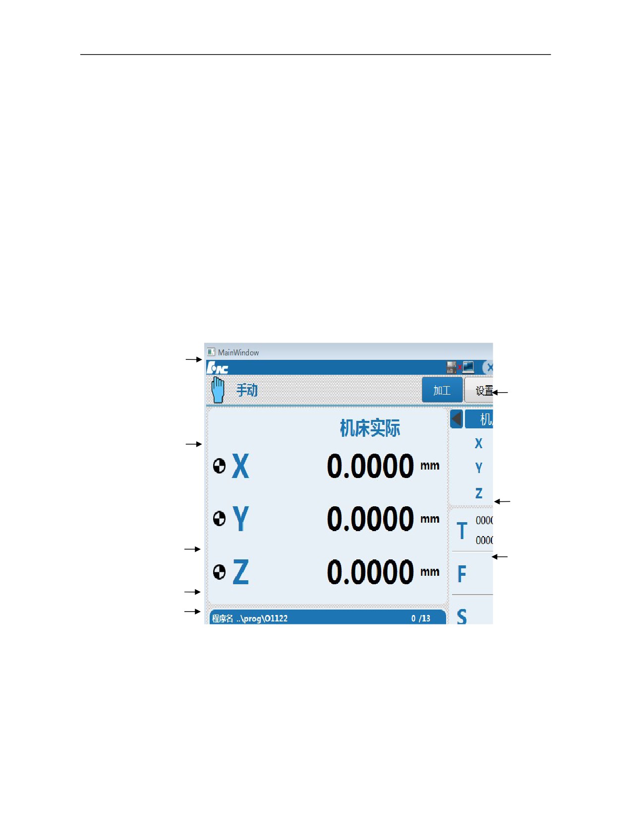
HNC-808Di-M system panel is 10.4 in. color LCD (resolution is 800×600). Panel zoning is
shown below.
(1)
(2)
(3)
(8)
(4)
(5)
(6)
(7)
14
HNC-8 System Operating Manual (Milling Machine)
(1)---LOGO
(2)---USB interface
(3)---Alphabetical keyboard area
(4)---Number and character key area
(5)---Cursor key area
(6)---Function key area
(7)---Soft key area
(8)---Screen display interface area
2.1.2 Display Interface Zoning
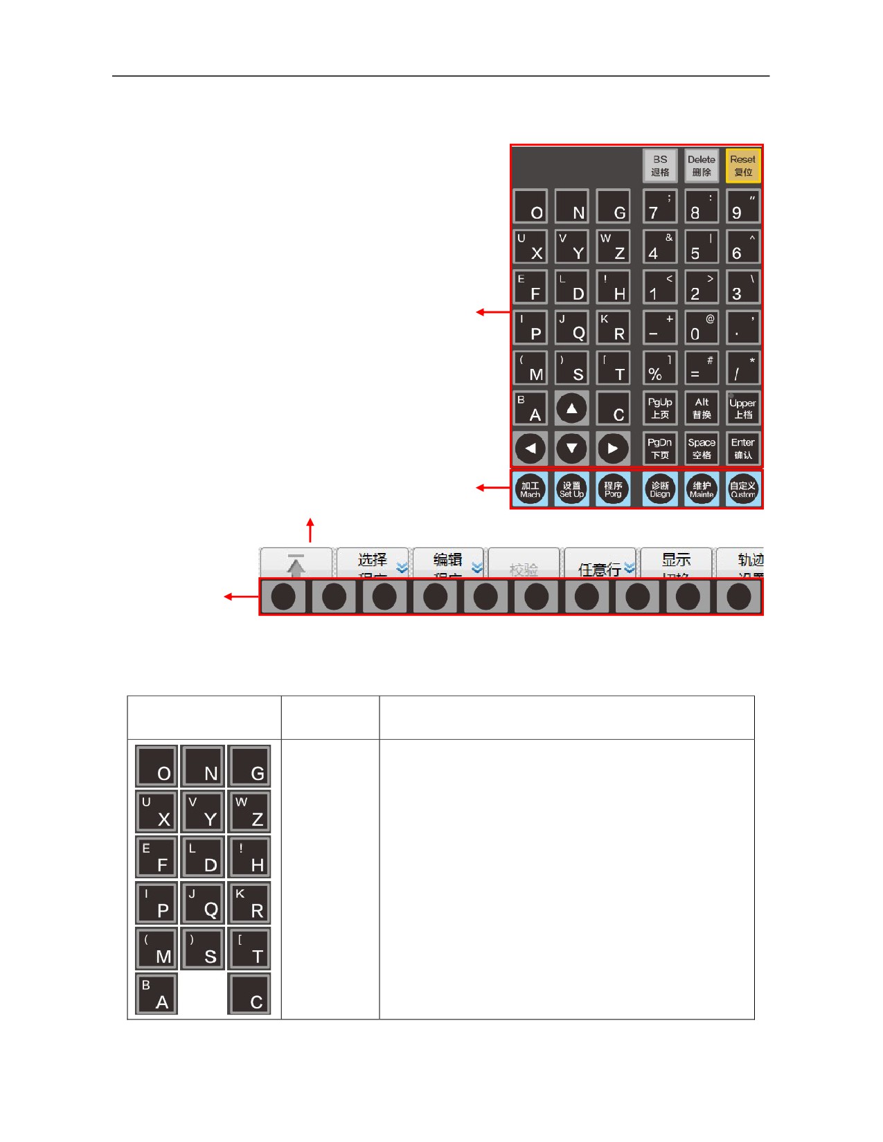
The operation interface of HNC-808Di-M CNC system is shown below
(1)
(6)
(2)
(7)
(3)
(8)
(4)
(5)
(1)
---Title bar
Machining mode: Working mode of the system can switch among auto, single
block, jog, incremental, reset, and emergency with corresponding keys on the
control panel of the machine tool;
System alarm message;
Level 0 main menu name: Display currently activated main menu keys;
15
HNC-8 System Operating Manual (Milling Machine)
Connection of USD flash disk and network:;
System logo, time.
(2)
---Graphics display window: Graphics displayed in this area differ with different
selected menu keys
(3)
---G code display area: Preview or display codes of machining program.
(4)
---Input box: Enter information to be inputted in this column.
(5)
---Menu command bar: Operate system functions through function keys in the menu
command bar.
(6)
---Axis status display: Display coordinate position, pulse value, breakpoint position,
compensation value and load current of axis
(7)
---Auxiliary function: T/F/S information area.
(8)
--G modal and machining information area: Display G modal and machining
information during machining.
2.1.3
Definition Of Host Panel Keys
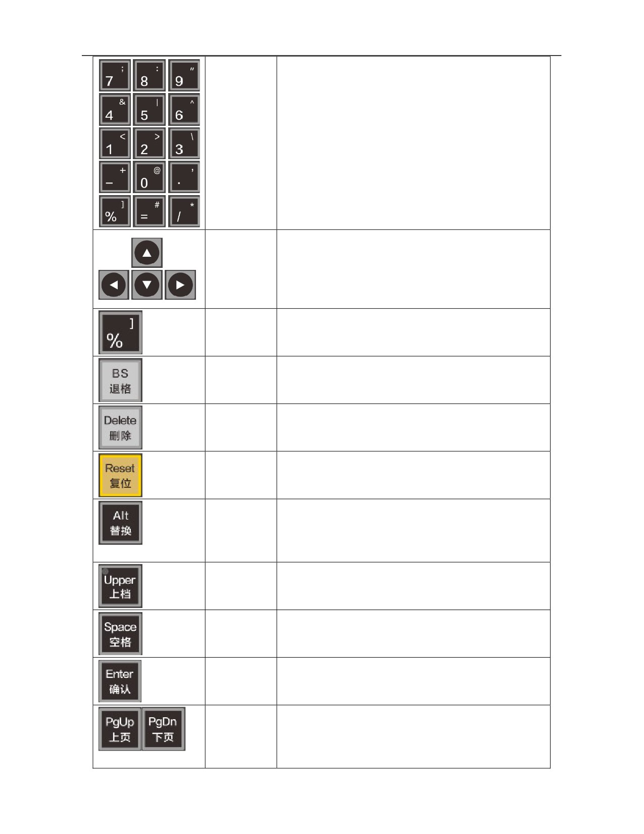
The host panel includes
Simplified MDI keyboard area, function key area, soft key area.
MDI keyboard function
Input and edit command by this keyboard. Most keys have functions of upper and
lower characters. Press "Shift" key and letter/number key simultaneously to input
the upper letter/number.
Function key function
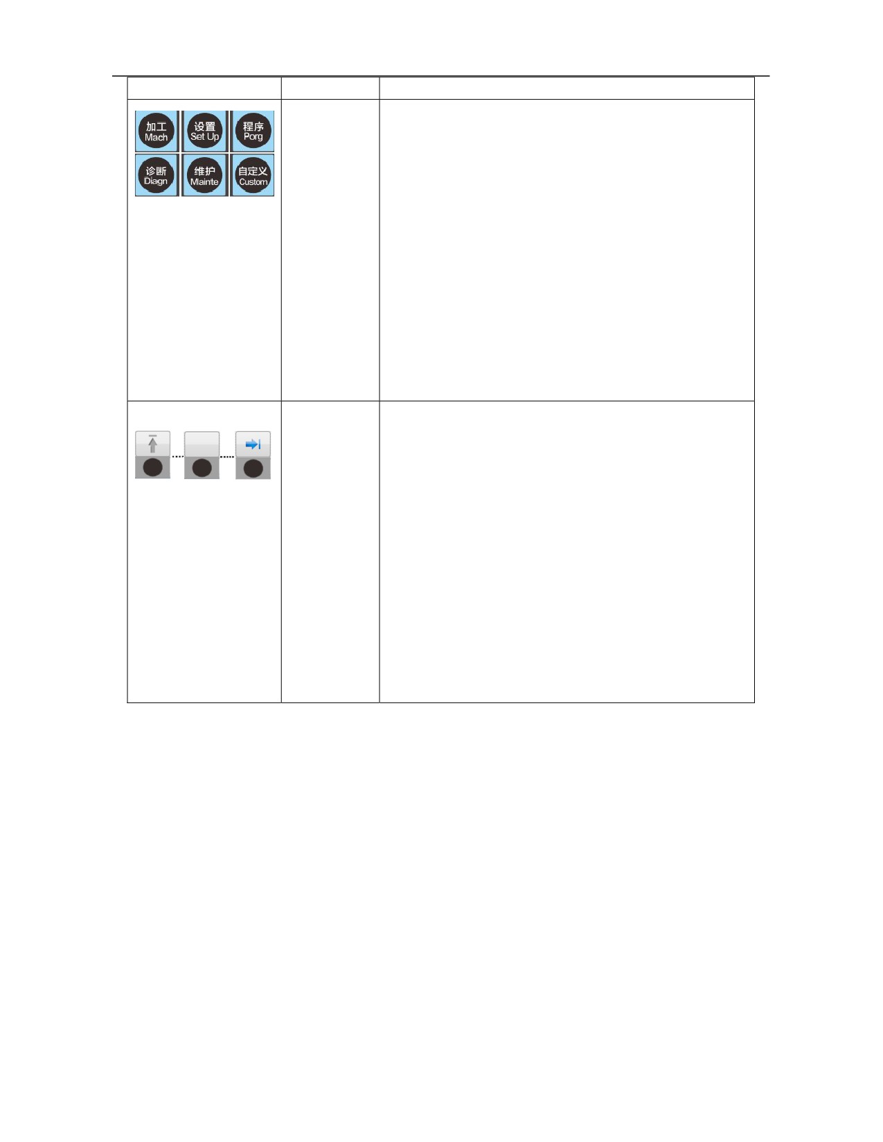
HNC-808Di-M system has 6 function keys "Machining", "Setup", "Program",
"Diagnosis", "Maintenance" and "User-defined", which correspond to different
function sets and display interfaces (for specific functions, refer to chapter 3).
Soft key function
There are 10 soft keys below the screen, on which there are no fixed signs. The keys
on the Left and right ends are to return to previous menu or continue the lower-level
menu key, and others are function soft keys. All soft key functions correspond to
menus displayed on the screen. The functions differ with change of menus (for
specific functions, refer to chapter 3).
16
HNC-8 System Operating Manual (Milling Machine)
MDI keyboard area
Function key area
(Menu screen display)
Soft key area
2.1.4 Function of Keys on MDI Keyboard
Key
Name/symbol
Functional description
Character key
Input letters, numbers and characters. Every character key has
(letter,
upper and lower characters. When the shift key and the
number,
character key are pressed simultaneously, the upper character
symbol)/
is input; otherwise, the lower key is input.
「 “Letter” 」
(such as「Y」)
17
HNC-8 System Operating Manual (Milling Machine)
Cursor shift
Control the cursor to move horizontally and vertically.
key/
「Cursor」
Program name
Based on the lower character, program name symbol of
symbol key/
subprogram
「%」
Backspace
Delete characters forward, and so on.
key/
「Backspace」
Delete key/
Delete current program and delete characters backwards, and
「Delete」
so on.
Reset key/
CNC reset, feed, input stop, and so on.
「Reset」
Alternate key/
Press 「Alt」「Cursor」 to switch content of the display frame
「Alt」
(position, compensation and, current, etc.) on the top right
corner of the interface. (Detailed in 3.2.1.5);
Press 「Alt」+「P」 for screenshot.
Shift key/
When the shift key and the character key are pressed
「Shift」
simultaneously, the upper character is input; otherwise, the
lower key is input.
Space key/
Move one blank space backward.
「Space」
Confirmation
Open and conform input.
key/
「Enter」
Page up or
Switch previous and next pages in the same display interface.
page
down
key/
「 Page
up or page
18
HNC-8 System Operating Manual (Milling Machine)
down」
Function key/
Machining: Select function set required for automatic
〖Machining〗
machining and corresponding interface.
〖Setup〗
Setup: Select function set relating to tool setting and
〖Program〗
corresponding interface.
〖Diagnosis〗
Program: Select function set for user program management
〖Maintain〗
and corresponding interface.
〖User-define
Diagnosis: Select function set for fault diagnosis, performance
d〗
commissioning and intelligence and corresponding interface.
Maintenance: Select relevant maintenance functions such as
hardware setup, parameter setup, system upgrade, basic
information and data management and corresponding
interface.
User-defined* (MDI): Select relevant functions of manual data
input and corresponding interface.
Soft key/
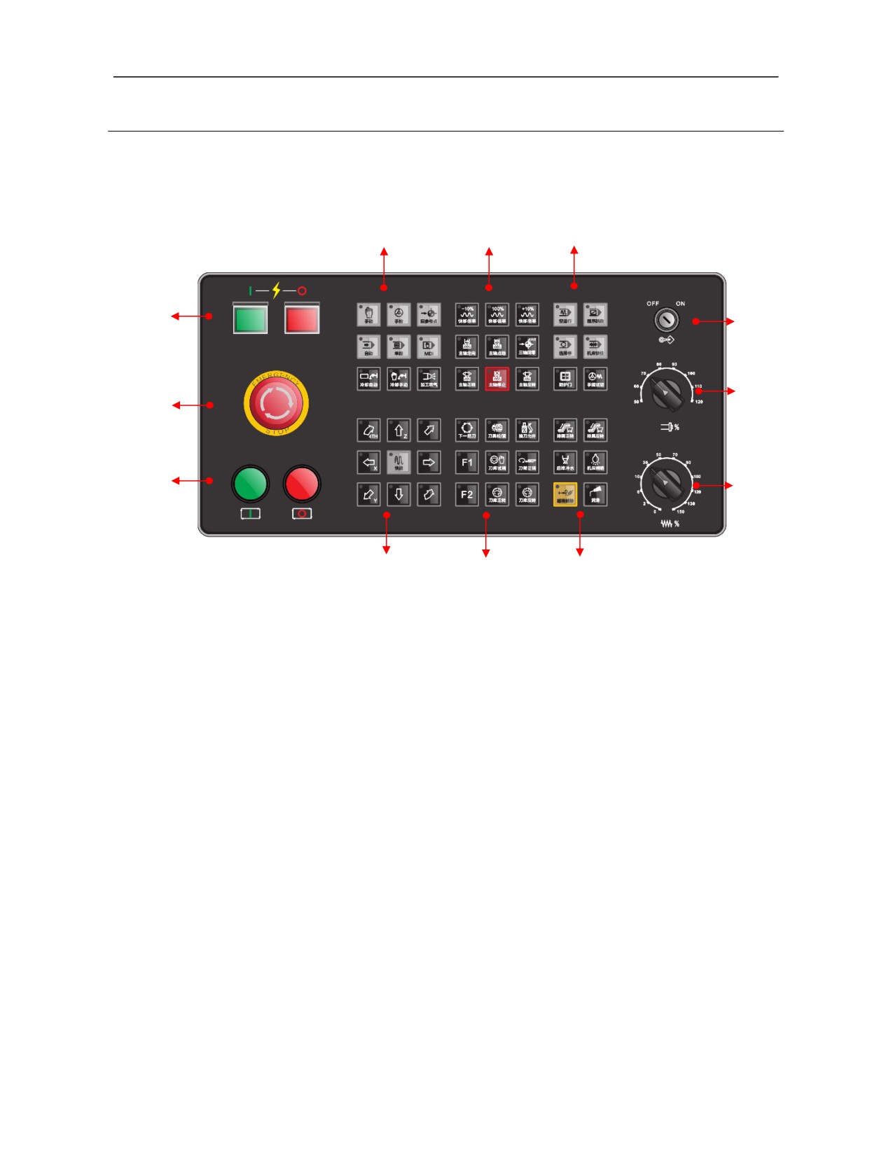
There are 10 unidentified keys below HNC-808Di-M display
screen, namely soft keys. In different function sets or levels,
『↑』
their functions correspond to those displayed on the screen.
『→』
Main functions of soft keys are as follows:
『 “Function”
1) Switch sub-interfaces in current function set;
』
2) Input corresponding operations in current function set, such
as edit, modify and data input, and so on.
In 10 soft keys, the leftmost key is to return to the previous
menu, arrow is valid when it is in blue, and it is in gray when
the function set menu is in the level 1.
In 10 soft keys, the rightmost key is to go to the next menu.
The arrow is valid when it is in blue. Press this key for cyclic
switch among interfaces in menus of the same level (menus of
the same level of this system has no more than 2 pages).
Note: In text descriptions in the subsequent chapters, the key name will be replaced with the key symbol.
19
HNC-8 System Operating Manual (Milling Machine)
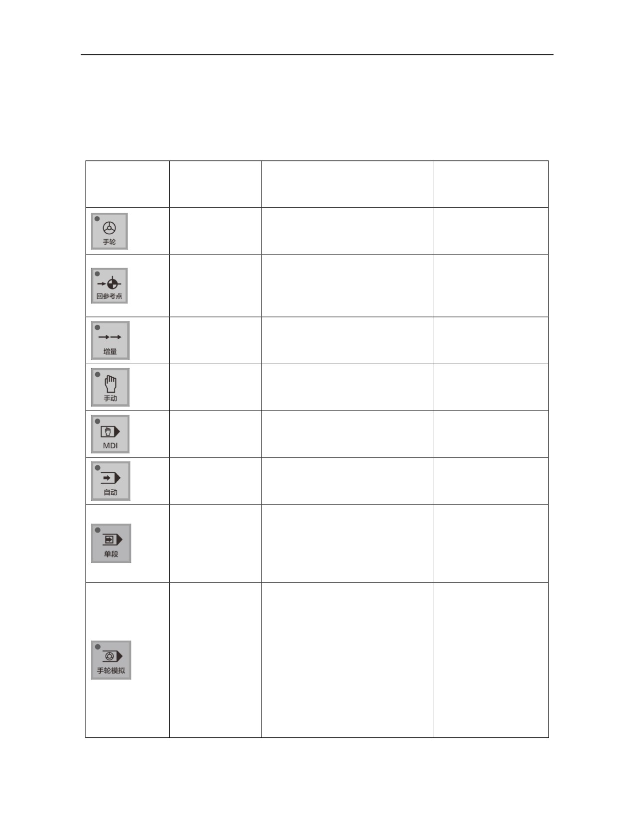
2.2 Operation Panel of Machine Tool (MCP Panel)
2.2.1 Operation Panel Zoning of Machine Tool
(12)
(11)
(10)
(1)
(9)
(8)
(2)
(3)
(7)
(4)
(5)
(6)
(1)---Power supply switch
(2) ---Emergency stop button
(3)---Cycle start/feed hold
(4)---Feed axis movement control key area
(5)---Machine tool control key area
(6)---Machine control extension key area
(7)---Feedrate override switch
(8)---Spindle override switch
(9)---Editing lock ON/OFF
(10)---Operation control key area
(11)---Rapid traverse override control key area
(12)---Working mode selection key area
20
2.2.2 Definition of Machine Operation Panel
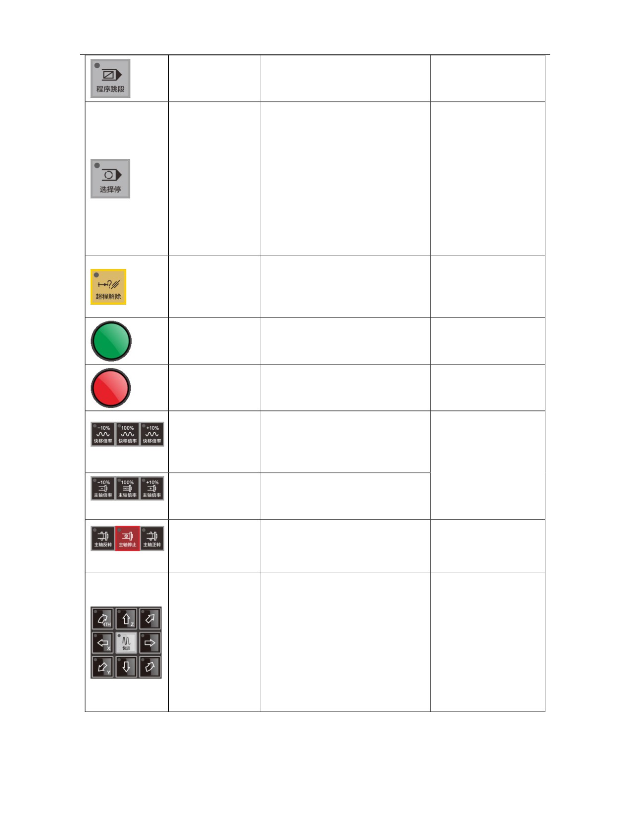
This manual describes function and status of all keys based on standard PLC of
HNC-808Di-M system. In case of discrepancies, please refer to the specification provided by
the machine tool manufacturer.
Working mode at valid
Key
Name/symbol
Functional description
state
Handwheel
Select the handwheel mode.
Working mode key
Handwheel
/【Handwheel】
Reference
point
Select the reference point return mode
return
key.
Reference point return
Working mode key
/【Reset】
Incremental
Select the incremental mode.
Working mode key
Incremental
/【Incremental】
Jog
Select the jog mode.
Working mode key
JOG
/【Jog】
MDI
Select MDI mode.
Working mode key
MDI
/【MDI】
Auto
Select the auto mode.
Working mode key
Auto
/【Auto】
1)
Switching of block-by-block
Single block key
operation or continuous operation
Auto, MDI
ON/OFF key
programs.
(Including single block)
/【Single block】
2) The indicator light lights up when
the single block is valid.
1) Whether to enable the handwheel
function.
2) When this function is enabled, the
handwheel controls the tool to run as
Handwheel
per the programmed path. While
Auto, MDI
ON/OFF key
/
rotating the handwheel CW, the
(Including single block)
[Handwheel]
subsequent programs continues to run;
while rotating the handwheel CCW,
the executed programs retracts in the
reverse direction.
21
Block skip
1) When a program block is prefixed
Automatic, MDI
ON/OFF key
with "/", whether to skip the program
(Including single block)
/[Block skip]
block.
1) When a program executes “M00”
command, whether to stop;
2) If this key has been pressed before
program execution
(indicator light
Optional stop
lights up), when the program executes
Auto, MDI
ON/OFF key
“M00” command, the feed hold is
(Including single block)
/ [Optional stop]
performed, and then press cycle start
to continue running the subsequent
programs. If this key is not pressed,
consistently run the program.
Overtravel release
1) Cancel limits of machine tool;
key
Handwheel,
jog,
2) Press and hold this key to release
/ [Overtravel
incremental
alarm and run the machine tool.
release]
Cycle start key
Auto, MDI
Run program and MDI commands.
/ [Cycle start]
(Including single block)
Feed hold key
Suspend
program
and
MDI
Auto, MDI
/ [Feed hold]
commands.
(Including single block)
Rapid traverse
speed override key
Override of rapid traverse speed.
Handwheel, incremental,
/ [Rapid traverse
jog, reset, auto, MDI
override]
(including single block
Spindle override
and handwheel)
key
Override of spindle speed.
/ [Spindle override]
Spindle control key
Control CW rotation, CCW rotation,
Handwheel, incremental,
/ [Spindle
and stop of spindle.
jog
CW/CCW rotation]
1) Control movement and direction of
axes under jog or incremental mode;
2) Select handwheel control axis under
Manual control of
handwheel mode;
Handwheel, incremental,
axis feed key
3) When an axis is pressed under jog
jog
/ [Axis feed]
mode, the axes run as per feedrate.
When the Rapid traverse key is
pressed at the same time, the axis run
as per rapid traverse speed.
22
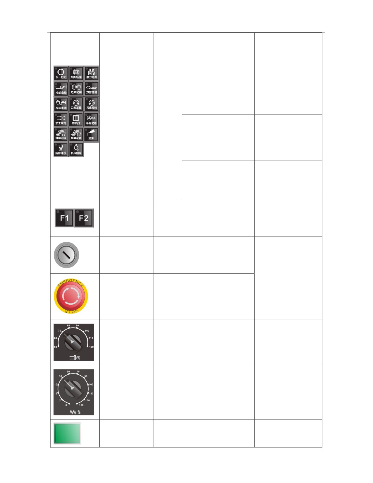
Next tool, tool loosening
and tightening, tool change
allowed, cooling manual,
magazine commissioning,
CW rotation of tool arm,
Jog
CW rotation of magazine.
Machine control
Manual
CCW rotation
of
key
control
magazine.
/ [Machine control]
of
auxiliary
actions
Handwheel, incremental,
of
Machine tool lighting,
jog, reset, auto, MDI
lubrication, rear row flush,
machine
(including single block
machining blowing
tool
and handwheel)
Handwheel
precutting,
Auto
protective door
Machine control
extension key
Manual control of auxiliary actions of
Set by machine tool
/
[Machine
machine tool.
manufacturer as needed
control]
Program protection
switch
Protect program from being modified
/
[Program
arbitrarily.
Handwheel, incremental,
protection]
jog, reset, auto, MDI
In case of an emergency, the system
(including single block
Emergency
stop
and the machine tool immediately
and handwheel)
button
enter the halt state, and all outputs are
/ [Emergency stop]
turned off.
Handwheel, incremental,
Spindle
override
jog,
auto,
MDI
key
Override of spindle speed.
(including single block,
/ [Spindle override]
handwheel simulation)
Feedrate knob
Feedrate override.
Jog, auto, MDI, reset
/ [Feedrate]
Handwheel, incremental,
System power-on
Control power-on of CNC device.
jog, reset, auto, MDI
/ [Power-on]
(including single block
23
and handwheel)
System power-off
Control power-off of CNC device.
/ [Power-off]
Note:
To simplify editing, keys in the specification are divided into working
mode key, function key, function soft key, NC key, MCP key, previous
menu key return key, and continud menu key, which are identified using
symbols in the following table.
Key
Working
Function
Function
NC
MCP
Previous menu
Continued
name
mode key
key
soft key
key
key
return key
menu key
Key
【】
〖〗
『』
「」
[ ]
『↑』
『→』
symbol
In text descriptions in the subsequent chapters, key name will be replaced
with key symbol.
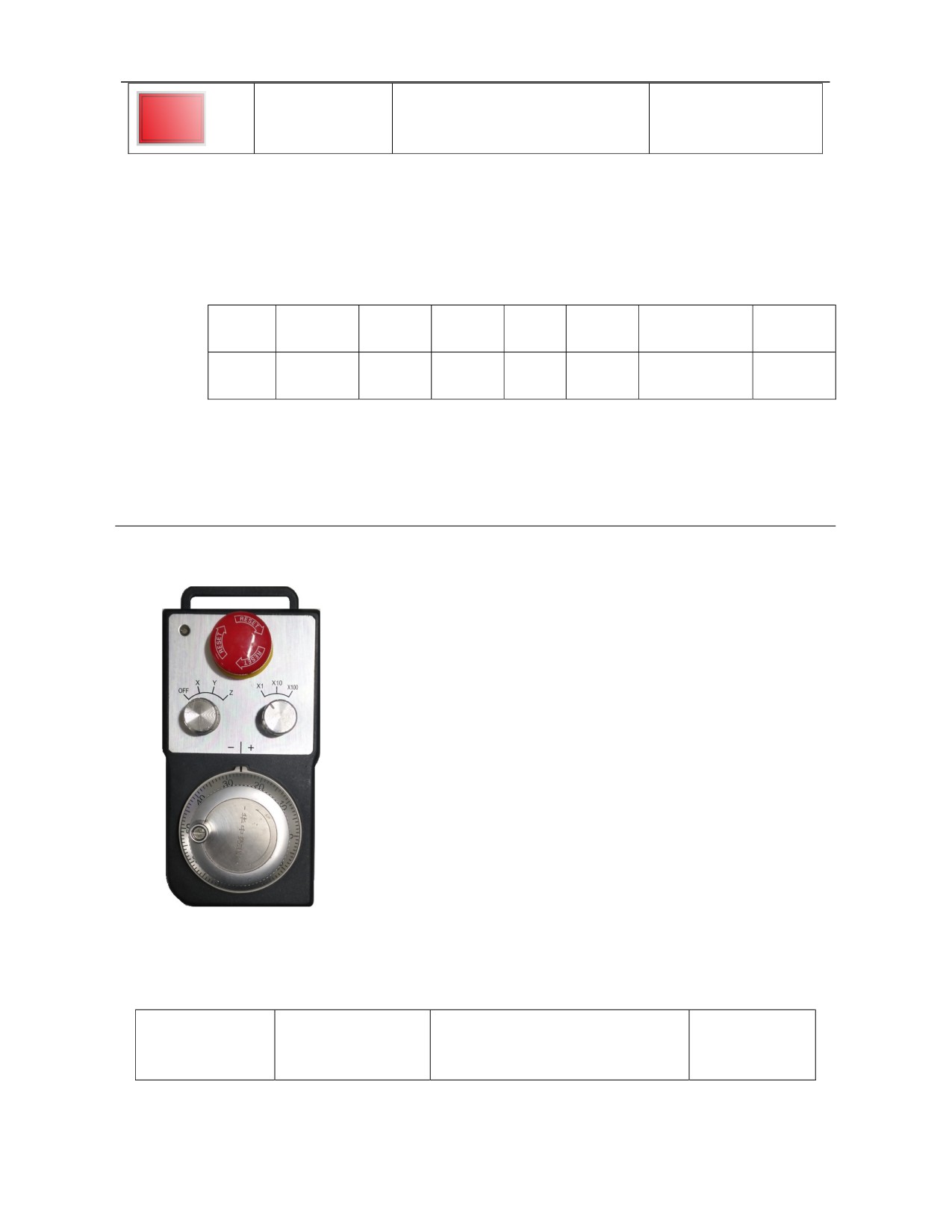
2.3 Handheld Unit
1. Handheld unit structure
Handheld unit consists of manual pulse generator, coordinate axis option
switch, magnification option switch, pulse enable switch, and emergency
stop switch. The structure diagram is shown below (specific appearance
and shape should be subject to actual model of order)
2. Function definition of keys of handheld unit
Working mode
Key
Name/symbol
Functional description
at effective state
24
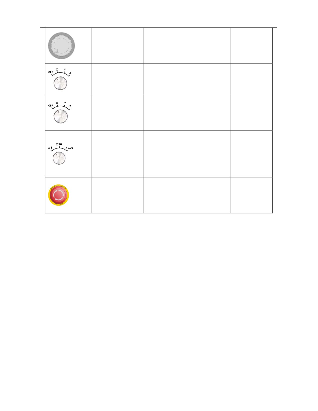
Control movement of machine tool.
Handwheel
(When handwheel function is valid, it
Handwheel
/ [Handwheel]
can control the machine tool to move
based on the programmed path).
When the switch is turned to “OFF”,
"MPG enable OFF"
all switches and keys except the
switch
Handwheel
emergency stop button on the handheld
/ [Enable OFF]
unit are invalid.
When the switch is turned to the axis
Axis option switch
selection h except “OFF”, all switches
Handwheel
/[X]\[Y]\[Z]\[4TH]
and keys on the handheld unit are
valid.
Tthe movement distance of the
Handwheel
machine
tool
is
magnification switch
0.001mm/0.01mm/0.1mm as the
Handwheel
/
[Incremental
handwheel rotates one graduation, or
magnification]
"Manual axis feed key" is pressed
once.
When the handwheel is valid, in case
Emergency
stop
Handwheel,
of an emergency, the system and the
button
incremental, jog,
machine tool immediately enter halt
/ [Emergency stop]
reset, auto, MDI
state, and all outputs are turned off.
25
//////////////////////