HNC-8 System Operating. Manual (Milling Machine) V2.4 Series - page 7
When the position of tool setter has never been
set, select the reference point;
Select whether to use
If "No" is selected, the steps of tool setter
7
the reference point
presetting will be skipped;
Perform the selection and confirmation based
on the steps 3, 4, and 6 above.
Select suitable measurement speed according
to Z axis height of the reference point;
Input
measurement
When the tool touches the tool setter, it is set
8
speed
as F50 by default;
Perform the selection and confirmation based
on the steps 3, 4, and 6 above.
II. Initial position presetting for tool setting
"Coordinates of reference point in X, Y and Z
directions" presets the initial position of tool
setting. During automatic tool setting, all tools
quickly reach this position from the safe point
Move the tool to the
Handwheel or
jog
axis
and then touch the tool setter at the
9
preset position of tool
movement key
measurement speed;
setter manually
On X and Y axes, try to make the tool in the
center of the tool setter;
On Z axis, ensure all tools do not touch the
tool setter while reaching this position.
Move the cursor to "Reference point
10
Press 「Cursor」
coordinates in X direction";
The system sets X axis position of current tool
as the X axis position of the tool setter in the
machine tool coordinate system;
Press
『 Current
11
Then, the position of Y and Z axes remains
position』
unchanged;
The value also can be set manually as per steps
3, 4 and 6.
Set reference point
12
coordinates in Y and Z
--
Repeat steps 10 and 11 respectively
directions
III. Safe position presetting
Move the cursor to "Machine tool coordinates H
of the lowest point on Z axis"
13
Press 「Cursor」
151
The lowest position of spindle, ensure all tools
Input machine tool
can touch the tool setter;
14
coordinates H of the
---
The shortest tool can press the upper surface of
lowest point on Z axis
the tool setter down within 5mm distance;
Input mode: "Jog" and "Current position".
Move the cursor to "Return to Z safe point after
tool setting";
15
Press 「Cursor」
This position is where the tool reaches quickly
Input tool setting and
after tool changing;
16
return to coordinates
--
This position should ensure that all tools
of Z safe point
cannot touch the tool setter;
Input mode: "Jog" and "Current position".
IV. Auxiliary action presetting
Input the command
Set if the tool setter has blowing function;
17
for the tool setter to
otherwise, it is 0 by default.
blow and hold the air
Refer to the slow-speed tool setting times s.
Input tool setting
18
The collision of the tool with the tool setter at
times
the first rapid drop is not counted.
V. Automatic tool setting and drop setup
Start tool setting;
After tool setting, save the measured value in
the external zero point Z offset;
Press
『 Start tool
19
If an alarm is given in the process of
setting』
measurement, the measurement is stopped, and
the measurement is performed again after
check and debugging.
Select the set workpiece coordinates
Select
workpiece
corresponding to the tool;
20
coordinate system
Select and conform as per the same steps as 3,
4 and 6.
"Drop setup" is to set the drop between the
Move the tool nose to
upper surface of tool setter and zero position of
the position where Z
Z axis of workpiece coordinates;
21
axis of the workpiece
--
This operation requires that the tool reaches Z0
coordinate system is 0
of workpiece coordinate accurately;
in handwheel mode
If the tool cannot reach Z0 of workpiece
coordinate, treat it after "Drop setup".
152
Drop is set when no machine tool runs. After
calculation, drop of Z axis is set in the selected
workpiece coordinate system;
If the tool cannot reach the workpiece
22
Press 『Drop setup』
coordinates Z0 position, but coordinates of the
tool on Z axis in the workpiece coordinate
system can be accurately identified, such as
"a", input "-a" in incremental mode based on Z
value of the set coordinate system.
Set
workpiece
23
coordinate such as
--
Repeat steps 20-22.
G55 and G56
8.3.3 Multiple Tools Multiple Workpiece Measurement
Operation
Multiple
tools
multiple
workpiece
Working
Jog, handwheel
name
measurement
mode
Basic
The machine tool is equipped with the
Display
"Auto tool setting" sub-interface
requirements
environment of tool setter test
interface
SN
Operation steps
Key
Description
I. Preparation for tool setting
Enter the default interface of "Setup"
1
Press 〖Setup〗
function set and level 1 menu.
Enter the "Auto tool setting" function
Press
『 Auto tool
2
interface.
setting』
Move the cursor to "Tool setting mode".
3
Press 「Cursor」
4
Press 「Enter」
Activate "Tool setting mode" drop-down box.
Select
"Multiple
Select "Multiple tools multiple workpiece".
5
tools
multiple
workpiece"
6
Press 「Enter」
Confirm the selection of "Tool setting mode".
Select whether to
When the position of tool setter has never
7
use the reference
been set, select the reference point;
153
point
If "No" is selected, skip over steps for
presetting the position of tool setting gage;
Select and conform as per the same steps as
3, 4 and 6.
Select
suitable
measurement speed
according to Z axis height of the reference
point;
Input measurement
8
When the tool touches the tool setter, it is
speed
set as F50 by default;
Perform the selection and confirmation as
per the steps 3, 4, and 6 above.
II. Presetting of initial position for tool setting
"Coordinates of reference point in X, Y and
Z directions" preset the initial position of
tool setting. During automatic tool setting,
all tools quickly reach this position from the
Move the tool to the
Handwheel or
jog
axis
safe point and then touch the tool setter gage
9
preset position of
movement key
at measurement speed;
tool setter manually
On X and Y axes, try to make the tool in the
center of tool setter;
On Z axis, ensure all tools do not touch the
tool settier while reaching this position.
Move the cursor to "Reference point
10
Press 「Cursor」
coordinates in X direction"
The system sets X axis position of current
tool as X axis position of the tool setter in
the machine coordinate system;
Press
『 Current
11
Then, the positions of Y and Z axes remain
position』
unchanged;
The value also can be set manually as per
steps 3, 4 and 6.
Set reference point
12
coordinates in Y and
--
Repeat steps 10 and 11 respectively.
Z directions
III. Safe position presetting
Move the cursor to "Machine tool coordinates
H of the lowest point on Z axis" column.
13
Press 「Cursor」
The lowest position of spindle, ensure all
Input machine tool
tools can touch the tool setter;
coordinates H of the
14
---
The shortest tool can press the upper surface
lowest point on Z
of the tool setter down within 5mm distance;
axis
Input mode: "Jog" and "Current position".
154
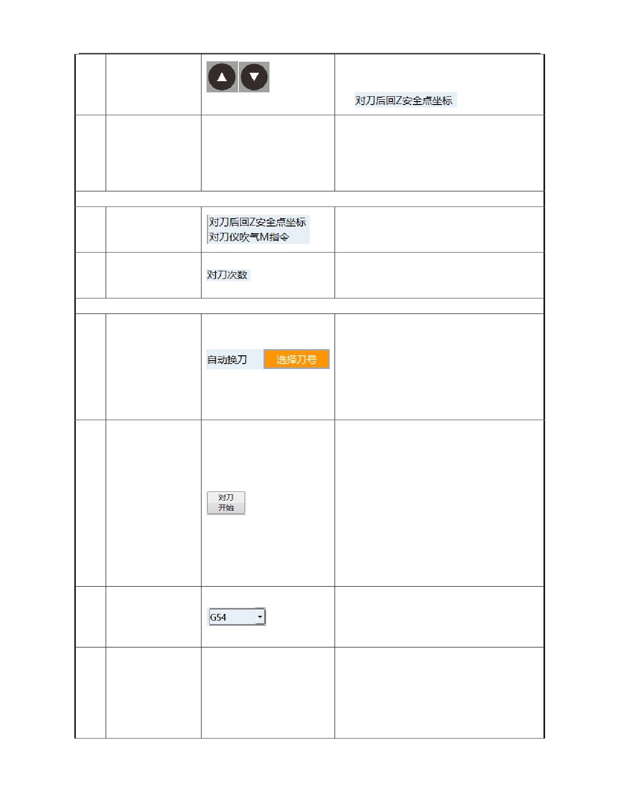
Move the cursor to "Return to Z safe point
after tool setting".
15
Press 「Cursor」
This position is where the tool reaches
Input tool setting
rapidly after tool changing;
and
return
to
16
--
This position should ensure that all tools
coordinates of Z safe
cannot touch the tool setter;
point
Input mode: "Jog" and "Current position".
IV. Auxiliary action presetting
Input the command
Set if the tool settere has blowing function;
17
for the tool setter to
otherwise, it is 0 by default.
blow and hold the air
Refer to the slow-speed tool setting times.
Input tool setting
18
The collision of the tool with the tool setter
times
at the first rapid drop is not counted.
V. Automatic tool setting and drop setup
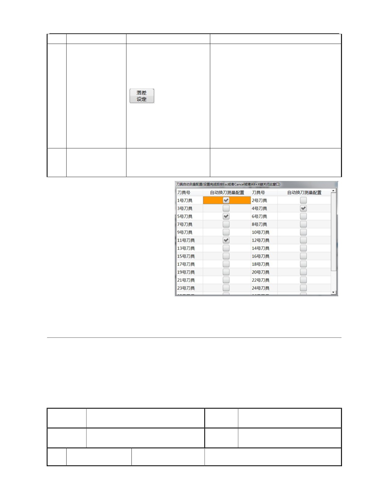
Select the pop-up of tool number list, and
select the tool number required for the tool
Set tool number for
setting;
19
automatic
tool
Support up to 32 tools;
setting
Detailed list of tool number is shown below;
Perform the setting and confirmation based
on the steps 3, 4 and 6 above.
The selected tools touch the tool setter
respectively to complete tool setting
automatically;
After tool setting, the measured value is
saved in tool length compensation of tool
Press
『 Start tool
20
compensation table, and tool compensation
setting』
number corresponds to the selected tool
number;
If an alarm is given in the process of
measurement, stop measurement and set the
tools after inspection and commissioning.
Select the set workpiece coordinates
Select
workpiece
corresponding to the tool;
21
coordinate system
Perform the setting and confirmation based
on the steps 3, 4 and 6 above.
Move the tool nose
"Drop setup" is to set the drop between the
to the position where
upper surface of tool setter and zero position
Z axis of the
of Z axis of workpiece coordinate;
22
--
workpiece
This operation requires that the tool reaches
coordinate system is
Z0 of workpiece coordinates accurately;
0 under handwheel
If the tool cannot reach Z0 of workpiece
155
mode
coordinates, treat it after "Drop setup".
Drop is set when no machine tool
movement. After calculation, drop of Z axis
is set in the selected workpiece coordinate
system;
If the tool cannot reach the workpiece
23
Press 『Drop setup』
coordinates Z0 position, but coordinates of
the tool on Z axis in the workpiece
coordinate system can be accurately
identified, such as "a", input "-a" in
incremental mode based on Z value of the
set coordinate system.
Set
workpiece
24
coordinates such as
--
Repeat steps 21-23.
G55 and G56
8.4 F/S machining Setup
When F and S commands are not used in machining program, this
function can be used to designate F and S values. This function also can
be used to modify default rotate speed of spindle.
When 010103 parameter value is set as 1 or includes 1, this function is
valid.
Operation
Working
Manual MS
Jog, auto
name
mode
Basic
When there is no F/S command in
Display
See Chapter 3 "Machining" interface
requirements
machining program
interface
SN
Operation steps
Key
Description
156
1
Press 〖Machining〗
Switch to the machining interface
2
Press 『Manual MS』
F and S setup menus pop up
If there are no F and S in machining program,
(Set machining F and
3
this value prevails
S values)
Set the default S (rotation speed in jog mode)
Note:
If there is no F/S value in the program, the value in the status bar can
be validated immediately.
If F/S has been set in the program, manual MS is invalid and data in
manual MS will be modified by the program.
157
9 Machine Tool Commissioning
9.1 System Upgrade
9.1.1 System Upgrade
Operation
Working
System upgrade
Emergency stop
name
mode
The machine tool must be at "Emergency
Basic
stop" state
Display
3.3
"Maintain" function set
requirements
The system upgrade package file name is
interface
interface
“**.BTF”
SN
Operation steps
Key
Description
1
Press 〖Maintain〗
Enter the "Maintain" function set interface
Press
『 System
2
Enter the System upgrade" sub-interface
upgrade』
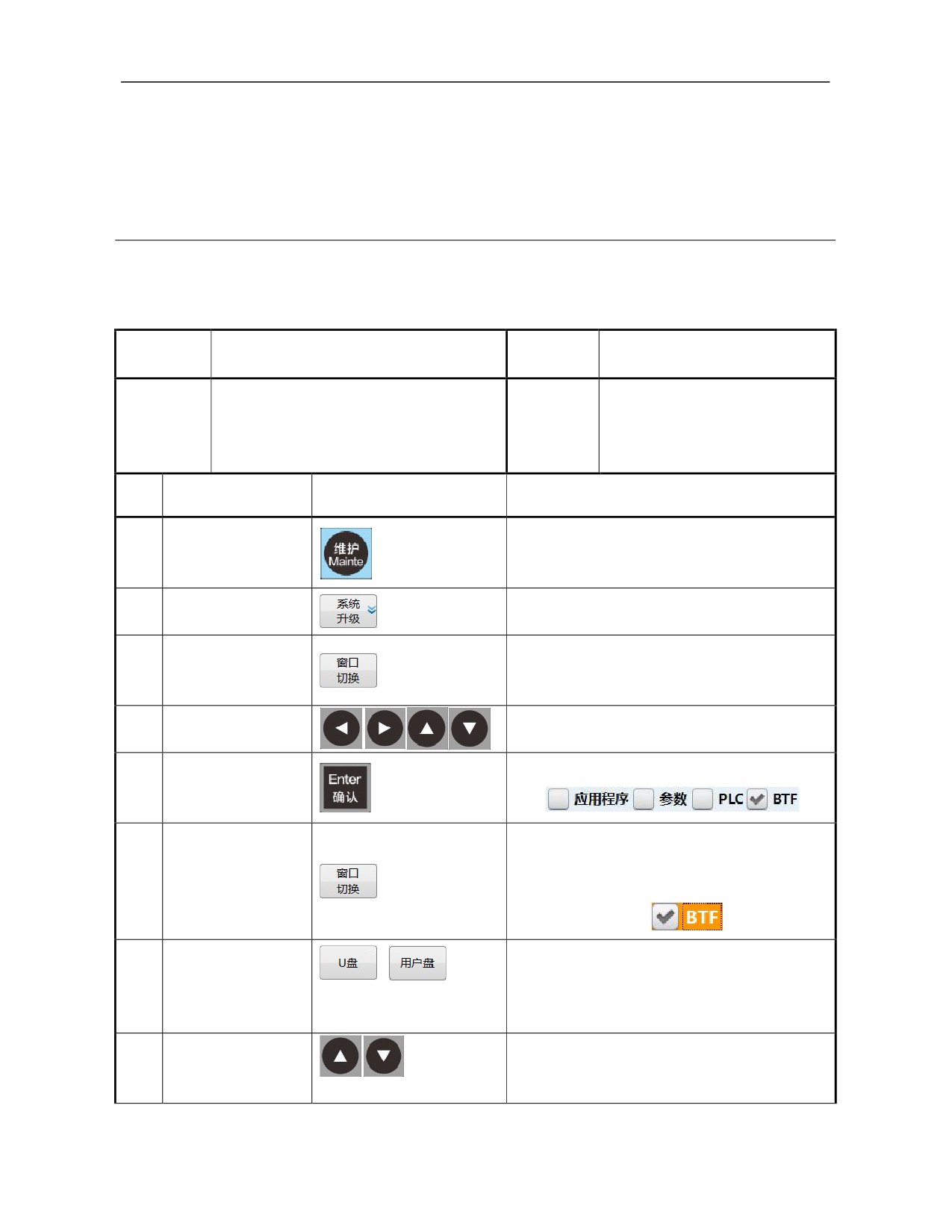
Switch to "Upgrade selection" window on the
Press
『 Window
3
upper part of the interface
switch』
Select the upgrade item
4
Press 「Cursor」
Select BTF item for comprehensive upgrade
Confirm the selected item
5
Press 「Enter」
Switch to the upgrade package file source
selection window on the lower part of the
Press
『 Window
6
interface.
switch』
Select the upgrade package file from USB
Press
『 USB flash
flash disk by default
7
disk』/『User disk』
The upgrade package file in the user disk also
can be selected
Select the upgrade file package
8
Press 「Cursor」
The upgrade pacakge file name must be BTF
file
158
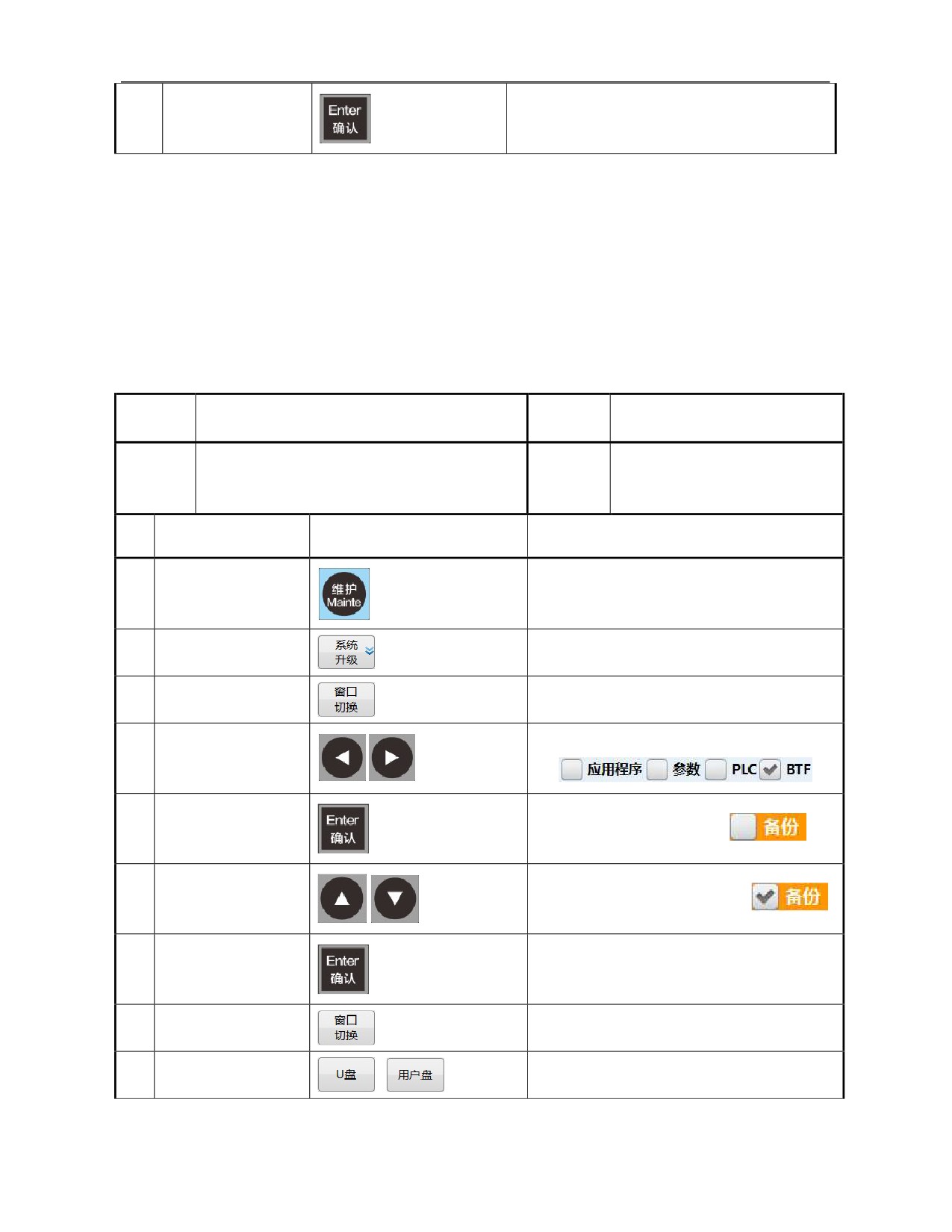
Start system upgrade
9
Press 「Enter」
Do not power off before the upgrade is
completed
Note
The upgrade should be conducted with the permission of system
administrator, and system upgrade is often conducted by HCNC
technical personnel;
The system must not be powered off in the upgrade process.
9.1.2 System Backup
Operation
Working
System backup
Emergency stop
name
mode
Basic
The machine tool must be at "Emergency stop"
Display
3.3
"Maintain" function set
requireme
state
interface
interface
nts
SN
Operation steps
Key
Description
1
Press 〖Maintain〗
Enter the "Maintain" function set interface
Press
『 System
2
Enter the System upgrade" sub-interface
upgrade』
Press
『 Window
Switch to the upgrade pacakge window on
3
switch』
the upper part of the interface
Select the backup item
4
Press 「Cursor」
5
Press 「Enter」
Confirm the selection
6
Press 「Cursor」
Select the backup item
7
Press 「Enter」
Confirm the backup
Press
『 Window
Switch the cursor to the backup target disk
8
switch』
window
Press
『 USB flash
The default backup target disk is the user
7
disk』/『User disk』
disk
159
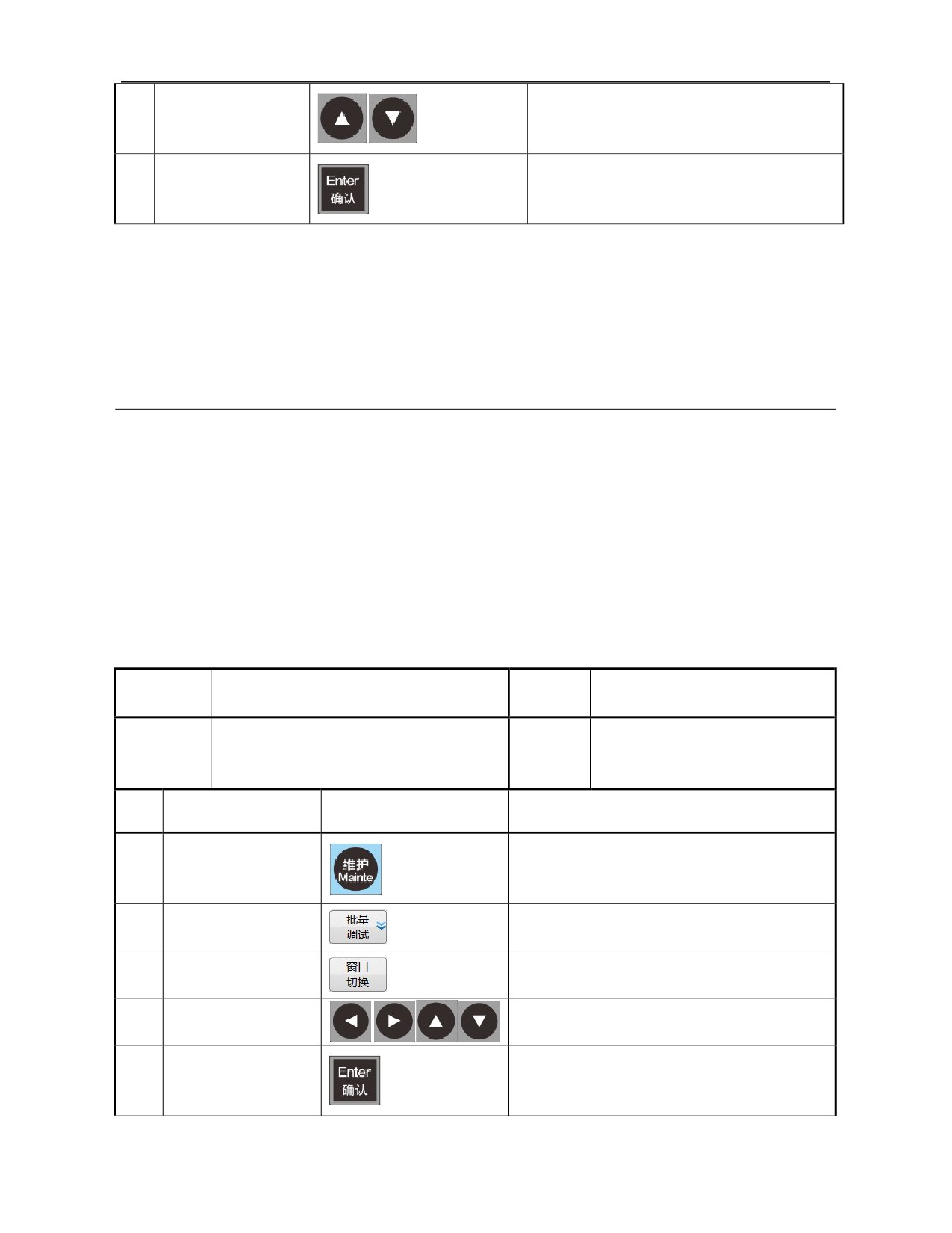
Move the cursor to the file directory to be
8
Press 「Cursor」
backed up
Start system backup
9
Press 「Enter」
Do not power off before backup is
completed
Note:
When a file is backed up in the system disk, size of the system disk
should be noted. Backup size of V2.40.00 software is about
200MB.
9.2 Batch Commissioning
This function is limited to permission. This function can load/back up
PLC, canned cycle, parameter, G code, parameter configuration and other
files required for commissioning separately/in batches.
Operation mode and object of "Batch commissioning" function are
similar to those of "Data management" function. There are more "Data
management" files and only a single file can be operated.
9.2.1 Batch Load Commissioning
Operation
Working
Batch load commissioning
Emergency stop
name
mode
The machine tool must be at "Emergency
Basic
Display
stop" state
3.3 "Maintain" function set interface
requirements
interface
Files loaded in batches must be .tar file
SN
Operation steps
Key
Description
1
Press 〖Maintain〗
Enter the "Maintain" function set interface
Press
『 Batch
Enter the "Batch
commissioning"
2
commissioning』
sub-interface
Press
『 Window
Switch to system disk
3
switch』
Enter file type selection window
Move the cursor to the type of the file to be
4
Press 「Cursor」
loaded
5
Press 「Enter」
Confirm the selection type
160
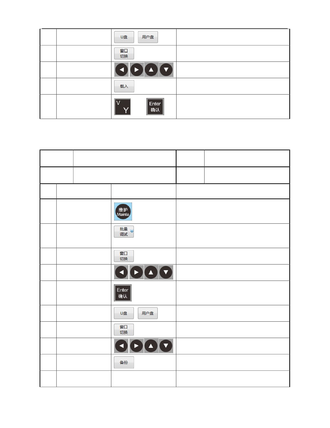
Press
『 USB flash
6
Select the source disk of the loaded file
disk』/『User disk』
Press
『 Window
Switch the cursor to the file source disk
7
switch』
window
Move the cursor to the type of the file to be
8
Press 「Cursor」
loaded
A prompt message "Whether to load file
9
Press 『Load』
XXXX.tar?(Y/N)"
Press
「 Y 」 or
A prompt message "File is successfully
10
or
「Enter」
loaded, please power off and restart!"
9.2.2 Batch Backup Commissioning
Operation
Working
Batch backup commissioning
Emergency stop
name
mode
Basic
The machine tool must be at "Emergency
Display
3.3 "Maintain" function set interface
requirements
stop" state
interface
SN
Operation steps
Key
Description
1
Press 〖Maintain〗
Enter the "Maintain" function set interface
Enter the "Batch commissioning"
2
Press 『Batch』
sub-interface
Press
『 Window
Switch to system disk
3
switch』
Enter file type selection window
Move the cursor to type of the file to be
4
Press 「Cursor」
backed up
5
Press 「Enter」
Confirm the selection type
Press
『 USB flash
6
Select a target disk to back up files
disk』/『User disk』
Press
『 Window
Switch the cursor to the file source disk
7
switch』
window
Move the cursor to the file directory to be
8
Press 「Cursor」
loaded
A prompt message "Please enter the backup
9
Press 『Backup』
package name " will be given
(Enter the backup
10
---
File name must be suffixed with .tar
package name)
161
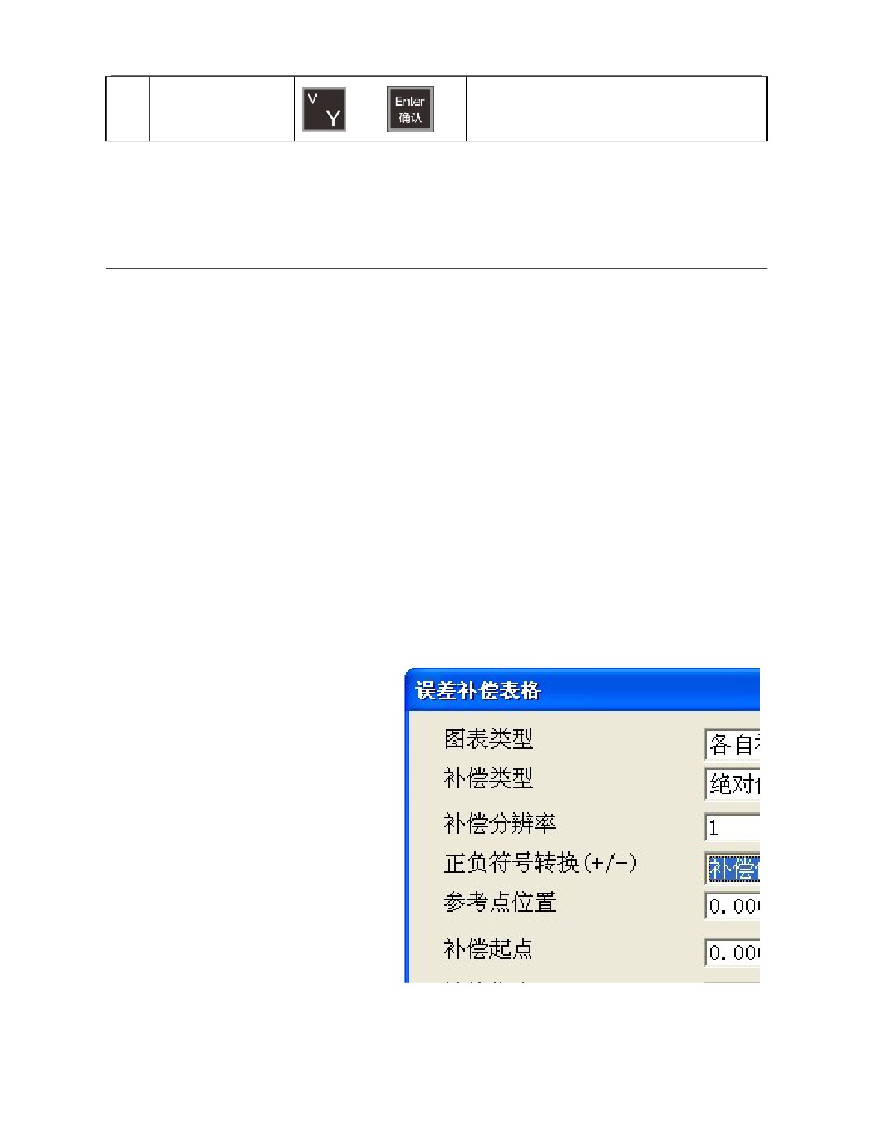
Press
「 Y 」 or
Complete the backup and give a prompt
11
or
「Enter」
message Backup succeeds
Note: Do not power off during backup or loading.
9.3 Pitch Error Compensation
Due to manufacturing error of machine tool, there is a certain error between
the actual position and the command position of machine tool axis. This
function can decrease the error of actual position and command position
through increasing or decreasing actual displacement of machine tool.
The laser interferometer can measure error between the actual position and
the command position of machine tool axis and generate error
compensation data file. The existing HNC-8D-TU system only supports
*.rtl file generated by Renishaw laser interferometer.
9.3.1 Generation Of Pitch Error Compensation Data File
Presently, the system supports direct import of error compensation data file
(*.rtl) generated by Renishaw laser interferometer only. When Renishaw
software generates the error compensation file, the error compensation
table should be set according to the following requirements (as shown
below).
"Chart type" must select "Separate compensation";
"Compensation type" must select "Absolute";
162
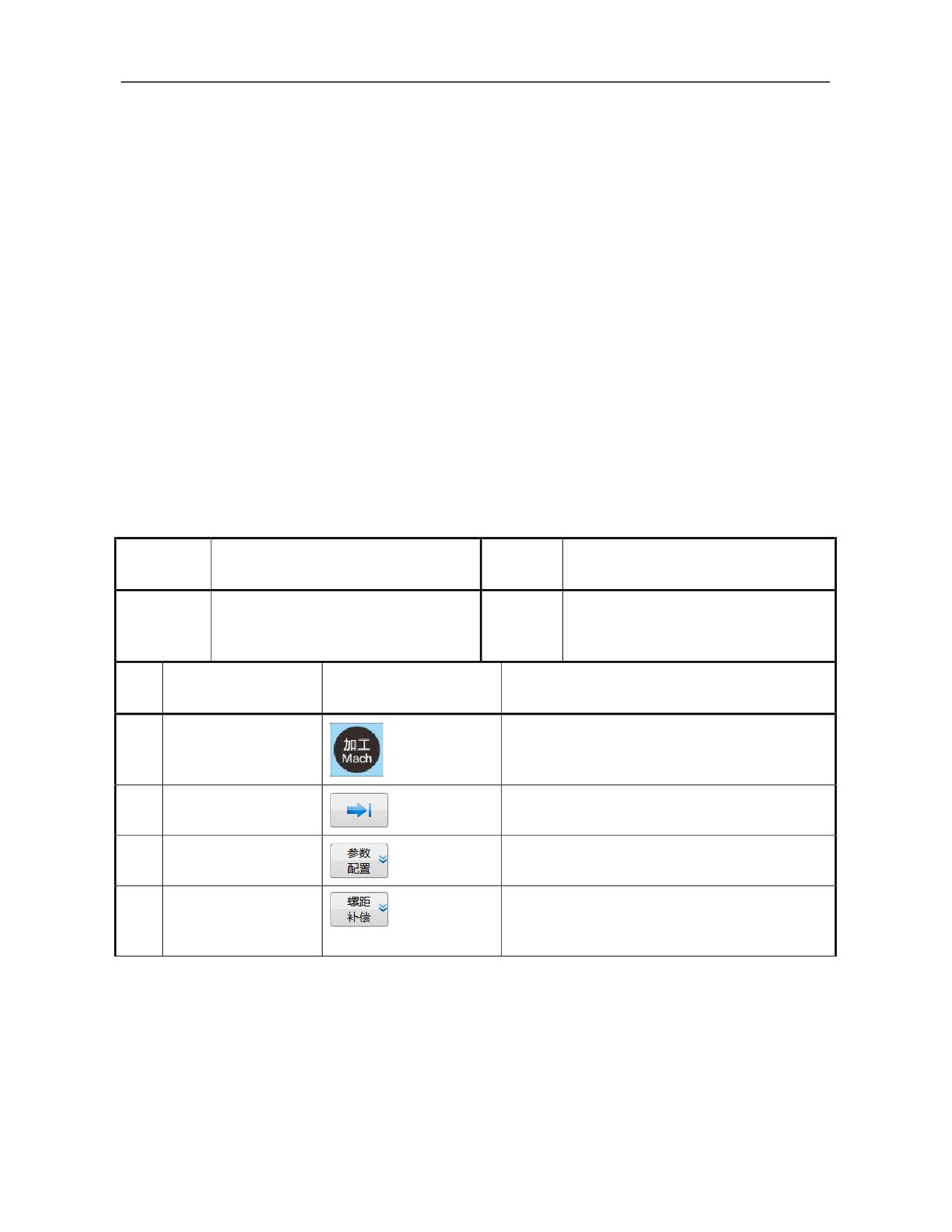
"Compensation resolution" must be "1"um;
"Conversion of plus and minus symbols (+/-)" must select
"Compensation value";
"Reference point " must be "0";
The "Compensation start point" is the machine coordinate position of
the compensation start point, it must be 0;
The "Compensation end point" is the machine coordinate position of
the compensation end point;
"Compensation interval" is the compensation interval and it must be a
positive value.
9.3.2 Operation of Pitch Error Compensation Sub-interface
HNC-8D-TU system can enter this function sub-interface under
"Machining" and "Maintain" function sets.
1) Under "Machining" function set, enter the pitch error compensation
sub-interface
Operation
Operation of pitch error compensation
Working
Auto, single block, jog, incremental
name
sub-interface
mode
3.2
"Tool
compensation
setup"
Basic
Display
The machine tool is at stop state
sub-interface under "Machining" function
requirements
interface
set
SN
Operation steps
Key
Description
1
Press 〖Machining〗
"Tool compensation setup" sub-interface
2
Press 『→』
Enter the extension menu
Press
『 Parameter
Enter the "Parameter setup" sub-interface
3
setup』
Press
『 Pitch
Enter the pitch compensation sub-interface (as
4
compensation』
shown below)
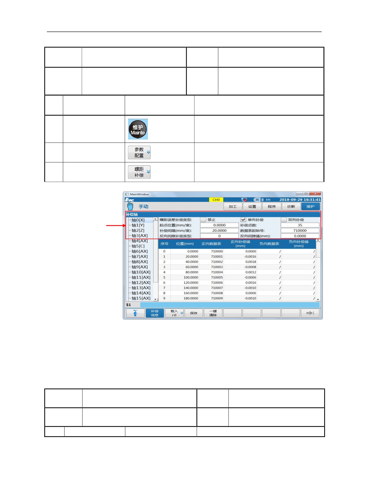
2) Under "Maintain" function set, enter the pitch error compensation
sub-interface
163
Operation
Operation of pitch error compensation
Working
Auto, single block, jog, incremental
name
sub-interface
mode
3.2
"Tool
compensation
setup"
Basic
Display
The machine tool is at stop state
sub-interface under "Machining" function
requirements
interface
set
SN
Operation steps
Key
Description
1
Press 〖Maintain〗
"Tool compensation setup" sub-interface
Press
『 Parameter
2
Enter the "Parameter setup" sub-interface
setup』
Press
『 Pitch
Enter the pitch compensation sub-interface (as
3
compensation』
shown below)
Area 1
9.3.3 Import of Pitch Error Compensation Data File
Direct import of pitch error compensation data file under the "Maintain"
function is introduced below (only available for direct import of rtl tpitch
error compensation file generated by Renishaw software).
Operation
Working
Import of pitch error compensation file
Auto, single block, jog, incremental
name
mode
Basic
Pitch error compensation data file has been
Display
3.2
"Tool compensation setup"
requirements
generated correctly
interface
sub-interface
SN
Operation steps
Key
Description
164
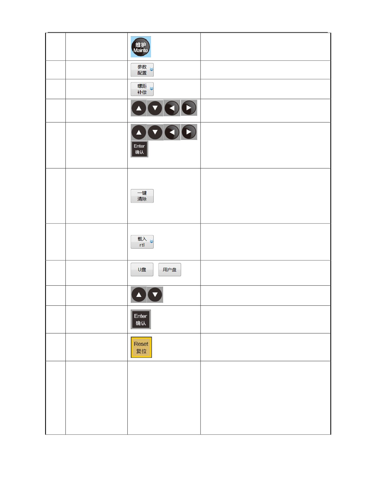
1
Press 〖Maintain〗
"Maintain" main menu
Press
『 Parameter
2
"Parameter setup" sub-interface and menu
setup』
Press
『 Pitch
"Pitch compensation" sub-interface and menu
3
compensation』
(as shown above)
4
Press 「Cursor」
Select compensation axis
Use the arrow keys to select the setting
options (the option in the area 1 of the above
Press
「 Cursor 」 or
5
figure, see notes for specific options)
「Enter」
Press "Enter" key to confirm the selection or
setting
If the pitch error compensation data is not
imported for the first time, please press
Press
『 One-click
One-click clear to clear thread compensation
6
clear』
data
If thread compensation data is imported for the
first time, this step can be omitted
Enter "Error compensation data file (*.rtl)"
for search
7
Press 『Load rtl』
Select the pitch error compensation data file
of corresponding axis thread
Press
『 USB flash
8
Select the compensation data file disk
disk』/『User disk』
9
Press 「Cursor」
Select the compensation data file
Press 「Enter」 to import the pitch error
10
Press 「Enter」
compensation data
After the pitch compensation data is imported
11
Press 「Reset」
successfully, press Reset to take effect
Check pitch error compensation type, start
point, compensation poins, compensation
interval and initial number of data table
(Check
thread
During unidirectional compensation type,
12
compensation data)
check whether backlash compensation is
enabled and the backlash value
If the pitch error compensation data is
imported incorrectly, execute from step 4 again
165
Remarks: Select options of area 1
Selection of compensation axis: Axis 0, axis 1 and axis 2
;
Pitch error compensation type: Inhibit, unidirectional compensation,
bidirectional compensation;
Start point
: The same as "Renishaw error compensation table";
Compensation interval: The same as "Renishaw error compensation
table";
Compensation points: The same as "Renishaw error compensation
table";
Initial number of data table: Initial number is: 710000;
Backlash compensation type: See parameter 300000 (which can be
set as 0, 1, 2);
Backlash value: See parameter 300001.
166

10 Use and Maintenance Information
10.1 Environmental Conditions
Operating conditions are shown below:
Environmental
conditions
Operating temperature
Nonfreezing at 0- +45
( C)
Temperature variation
<1.1C/min
90%RH or lower (non-condensable)
Normal condition: 75% or smaller
Relative humidity
Short-term (within a month): No more
than 95%
Storage temperature ( C)
Nonfreezing at -20- +60
Storage humidity
Non-condensation
Indoor (sunproof)
Surroundings
Anticorrosive, burn, frog, dust
No more than 1000m above the sea
Height
level
Vibration (m/s)
5.9(0.6G) or lower at 10-60Hz
10.2 Grounding
Correct grounding is very important for electrical device and it is
aimed at:
protecting workers from electric shock arising from abnormal
phenomena;
Protect electronic devices from interference of the machine and
other electronic devices nearby, which may result in abnormal
operation of control device.
While installing machine tool, it must be reliably grounded and neutral
line in the power grid cannot be used as earth wire; otherwise, personal
injury or device damage may be caused and exceptional operation of
device may be caused.
167

10.3 Power Supply
Power of HNC-808Di-TU CNC device is supplied by the electrical
control cabinet of the machine tool. For power supply of machine tool,
please refer to installation manual of machine tool.
10.4 Dust Removal Of Filter Fan Screen
Fan is an important element for ventilation and heat dissipation of CNC
device. In order to prevent dust from entering the device from the fan,
filter screen is set at air inlet and air outlet.
Dust will gradually stop up the filter screen after long-term use and
consequently ventilation conditions will worse and even normal operation
of devices will be affected. Thus, the user should regularly clean all filter
screens. Generally, filter screen of fan should be cleaned every three
months and cleaning period should be reduced under poor conditions.
10.5 Use After Long-time Idle
If CNC device is used after left unused for a long time, remove dust and
dry it. Then, check connection and grounding, power on for a period of
time and ensure the system is faultless before restart.
168