Series HSV-180AD AC Servo Amplifier. User's Manual (V1.00 2012.4) - page 6

Gain switching
P
6
1̚10000
5
the same as above
hysteresis width
Unit˖ms
Gain switching lag
Gain switching
P
7
0̚10000
2
time
conditions are met to
start switching time
Unit˖ms
Set the position gain
Position gain switch
P
8
0̚1000
5
first-order low-pass
delay time
filter when gain
switching
Zero speed output
PˈS
9
1̚100
10
Unit˖ 1rpm
detection range
Unit˖ms
Servo motor delay
Time of input PWM
P, S
10
0̚3000
20
caused by power off
after servo OFF
delay
PˈS
11
Weakening speed
1000̚4500
1800
Unit˖ 1rpm
Torque inertia ratio
PˈS
12
10̚20000
880
Unit˖(Nm/Kgm2 )
value
PˈS
13
Load inertia ratio
10̚300
10
Unit˖0.1
Digital output O4
PˈS
14
-9̚+9
8
Refer to function O1
function
0˖ Invalid Input
1˖ Servo enable
2˖ Alarm Clear
3˖ Deviation Clear
4˖ Pulse ban
Digital inputs I1
5˖ Reverse over
PˈS
15
-16̚+16
1
function
travel
6˖ Forward over
travel
7˖ Zero speed lock
8˖ Gain switch
9˖ Electronic gear
125
switch 0
10˖Electronic gear
switch 1
11˖ Positive torque
limit
12˖ Negative
torque limit
13˖ Emergency
stop switch
14˖ Internal speed
selection 1
15˖Internal speed
selection 2
16˖Internal speed
selection 3
The negative sign
indicates input level
negated
Digital inputs I2
PˈS
16
-16̚+16
2
the same as above
function
Digital inputs I3
PˈS
17
-16̚+16
3
the same as above
function
Digital inputs I4
PˈS
18
-16̚+16
4
the same as above
function
Digital inputs I5
PˈS
19
-16̚+16
-5
the same as above
function
Digital inputs I6
PˈS
20
-16̚+16
-6
the same as above
function
0˖ Invalid
1˖ Forced valid
2˖ Servo ready
3˖ Alarm Output
4˖ Reach zero
Digital Output O1
PˈS
21
-9̚+9
5
speed
function
5˖ Positioning
completed
6˖ Speed reached
7˖ Torque limits
8:Electromagnetic
126
brake output
9˖ Zero speed
Locking minus sign
indicates that the
output level is
inverted.
Digital Output O2
PˈS
22
-9̚+9
2
the same as above
function
Digital Output O3
PˈS
23
-9̚+9
3
the same as above
function
-6000̚
S
24
Internal speed 1
0
1r/min
6000
-6000̚
S
25
Internal speed 2
0
1r/min
6000
-6000̚
S
26
Internal speed 3
0
1r/min
6000
-6000̚
S
27
Internal speed 4
0
1r/min
6000
-6000̚
S
28
Internal speed 5
0
1r/min
6000
-6000̚
S
29
Internal speed 6
0
1r/min
6000
-6000̚
S
30
Internal speed 7
0
1r/min
6000
-32767̚
31
State control 2
STB15-STB0
32767
The first notch
PˈS
32
100̚2000
1500
Hz
frequency
The first notch
PˈS
33
0̚20
2
width
The first notch
PˈS
34
0̚100
0
depth
The second notch
PˈS
35
100̚2000
1500
Hz
filter frequency
127

The second notch
PˈS
36
0̚20
2
filter width
The second notch
PˈS
37
0̚100
0
filter depth
0˖ Notch filter is
invalid
1˖Notch filter 1 is
Notch filter
valid
PˈS
38
0̚3
0
application mode
2˖Notch filter2 is
valid
3˖Notch filter1,2
are valid
Moving Average
Position command
P
39
0̚31
0
number of position
smoothing factor
command FIR filter
Motor feedback
output to the number
Feedback pulse
1000̚
PˈS
40
2500
of pulses per
output divider factor
15000
revolution of the PC
˄×4˅
Unit:Pulse
PC output pulse
number
corresponding to the
Command pulse
motor rotation lap
input
˄×4˅
Corresponding
1000̚
When STB4 zero,
P
41
2500
motor
25000
electronic gear
Feedback pulse
parameters PA13,
number
PA14 valid
When STB4 1,
electronic gear for
the servo motor
revolution needed to
128
command input
pulse direct
calculation.
At this time, the
electronic gear
parameter is invalid.
ƹMotor rated
PˈS
42
300̚15000
680
0.01A
current
ƹRated motor
PˈS
43
100̚9000
2000
1r/min
speed
Note: The label ƹ parameters will be automatically configured in the PA-43.
7.2.3 Description of the parameter setting:
PA--17
Default
NO.
Parameter
Scope
Unit
value
PA--17
Maximum speed limit
100̚12000
2500
1r/min
Function and setting:
1ǃ According to motor type set maximum speed of the servo motor.
2ǃ Regardless of the direction of rotation.
PA--24
Default
NO.
Parameter
Scope
Unit
value
PA--24
Magnetic logarithm of
1̚12
3
servo motor
Function and setting:
1ǃ According to motor type set maximum speed of the servo motorDŽ
PA--25
Default
NO.
Parameter
Scope
Unit
value
PA--25
Servo motor encoder
0̚7
4
optical -electrical
resolution
Function and setting:
1ǃ PA--25must be filled in based on the technical data of the motor.
129
ǃSetting parameters˖
0˖1024pps
1˖2000pps
2˖2500pps
3˖6000 Sine and cosine incremental encoder
4: ENDAT2.1 encoder
5˖BISS encoder
6: HiperFACE encoder
7: TAMAGAWA encoder
8,9:Reserved
PA--26
Default
NO.
Parameter
Scope
Unit
value
PA--26
Encoder zero offset
-32767̚32767
0
Function and setting:
1ǃ Set encoder zero offset
2ǃ Adapter Dench motor mounting incremental encoder
(PA--25=0,1,2,3),the parameter is the number of pulses distance to zero
pulse..
3ǃ When the motor encoder is absolute encoder, the parameters is the
number of pulses at 16 bit resolution for conversion.
Dench GK6˄8˅ servo motor
GK6(8)-XXX-XXX61-JE(JB) JE(JB) means installation Heidenhain
EQN1325 encoder
At this time: GK6(8)-XXX-XXX61-JE(JB) JE(JB);
PA--42
Default
NO.
Parameter
Scope
Unit
value
PA--42
Motor rated current
300̚15000
680
0.01A
Function and setting:
1ǃSet the motor rated current;
2ǃThe parameters will be adjusted automatically after matching PA—43.
130
PA--43
Default
NO.
Parameter
Scope
Unit
value
PA--43
Motor rated speed
100̚9000
2000
1r/min
Function and setting:
1ǃSet the motor rated speed;
2ǃThe parameters will be adjusted automatically after matching PA—43.
7.2.4 Parameters Related to Movement Control
PA--0
Default
NO.
Parameter
Scope
Unit
value
PA--0
Position proportional gain
20̚10000
400
0.1Hz
Function and setting:
1. Set position proportional gain.
2. The greater of the parameter value, the greater of the gain and the rigidity, and the
smaller of the position lag value at the same frequency of the command pulse. Note:
the value is too large may cause oscillation or overshooting.
3. The parameter value is determined according to the type of Servo Amplifier and
operating load.
PA--1
Default
NO.
Parameter
Scope
Unit
value
PA--1
Position forward gain
0̚150
0
1%
Function and setting:
1. Set Position forward gain
2. When setting 100%, position lag is always 0 in any frequency command pulse.
3. The greater of gain the position loop, the greater of the high speed response
characteristic of the control system, but it will make the system more prone to
oscillation.
4. The parameter is usually set to 0 when there is not need very high response
characteristics
131
PA--11
Default
NO.
Parameter
Scope
Unit
value
Positioning complete
0̚3000
100
0.0001r
PA--11
range
Function and setting:
1ǃSet the, positioning complete pulse range under position control mode
PA--11 * 0.0001 * motor pulses
If set PA--11 = 1000, motor runs 10000 pulses per revolution. Positioning complete
range is 1000 * 0.0001 * 10000 = 1000 pulses.
2ǃThis parameter judges whether Servo Amplifier complete positioning under the
position control mode. when the remaining pulse in the deviation counter is less than
or equal to the parameter setting range, it means the Servo Amplifier has been
complete positioning. The positioning complete switch signal output ON, otherwise
OFF.
3ǃUnder the position control mode(PA--23=0), output positioning complete signal.
PA--12
Default
NO.
Parameter
Scope
Unit
value
Range of position
1̚100
20
0.1 ring
PA--12
tolerance
Function and setting:
1ǃSet range of position tolerance:
PA--12 * 0.1 ring
Or (PA--12 * 0.1 * motor pulses) pulse.
2ǃUnder the position control mode (PA--23=0), when the position deviation counter
exceeds the range of the parameter, the Servo Amplifier gives alarm.
If set PA--12 = 20, motor runs 10000 pulses per revolution. Then the Range of
position tolerance: 20 * 0.1 = 2or20 * 0.1 * 10000 = 20000 pulses
PA—13/14
Default
NO.
Parameter
Scope
Unit
value
Position command pulse
1̚32767
1
PA--13
frequency molecular
Position command pulse
1̚32767
1
PA--14
frequency denominator
Function and setting:
132
1ǃSet the position command pulse sub-octave (electronic gear)
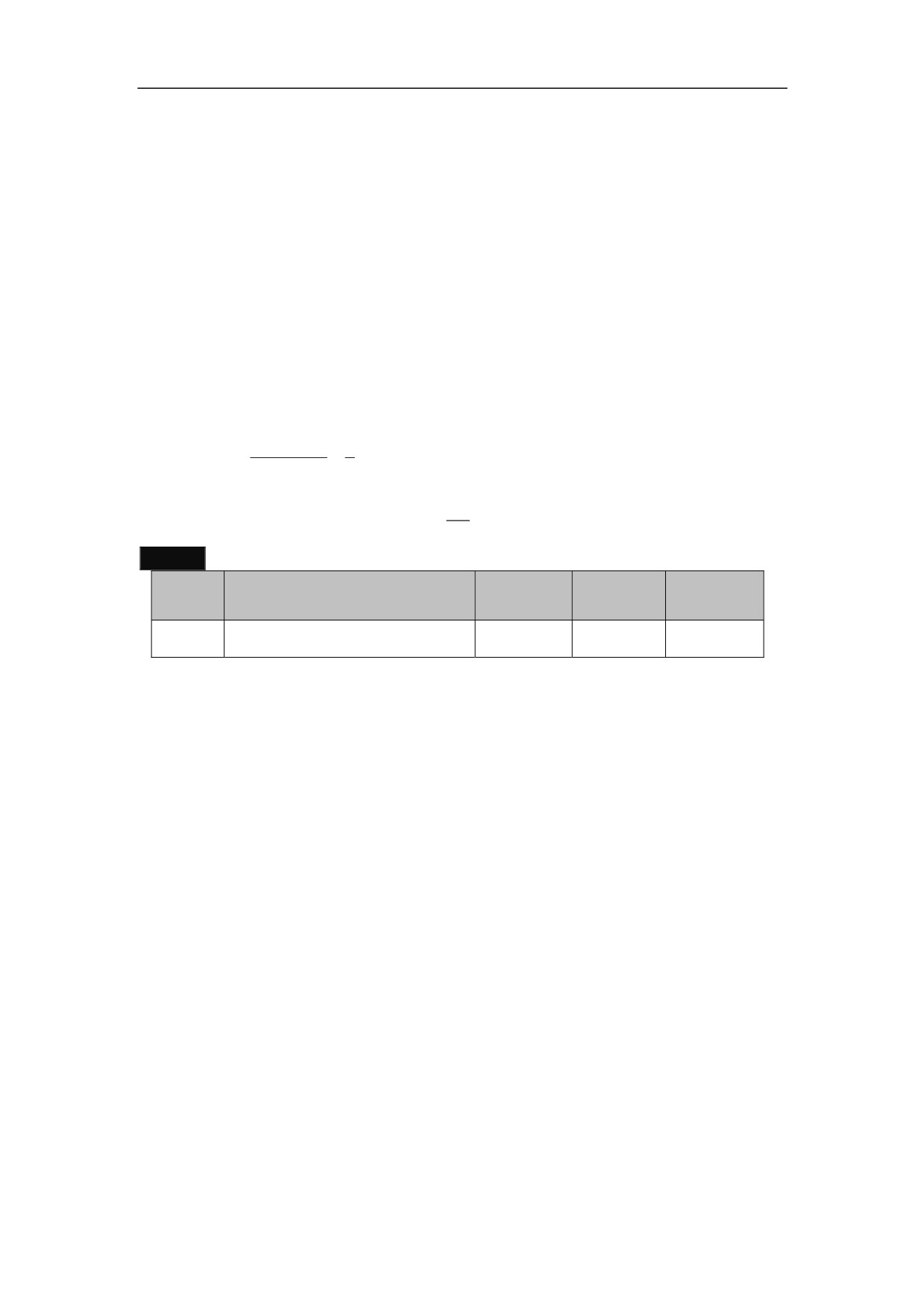
2ǃUnder position control mode (PA - 23 = 0), through setting the PA - 13 and PA -
14 parameter, could be easily matched with a variety of pulse source, in order to
achieve ideal control resolution (angle / pulse)
3ǃP×G=N×C
P: the number of pulses input commands
G: electronic gear ratio G=Position command pulse frequency molecular/ Position
command pulse frequency denominator
N: motor rotation number;
C: the motor encoder pulses
4ǃIf instruction input pulse is 6000, the servo motor rotates 1 circles, the motor
encoder is 2500 lines of incremental photoelectric.
125004
5
G
N C
P
6000
3
Setting PA—13 to 5, PA—14 to 3
1
5ǃThe range of electronic gear ratio is
G
50
50
PA--22
Default
NO.
Parameter
Scope
Unit
value
PA--22
Command pulse input mode
0̚3
1
Function and setting:
1. Set parameters to the command pulse mode
2. Set parameters to one of the 3 types of input mode.
z
0: indicates two-phase positive pulse input
z
1: indicates pulse + direction
z
2: indicates CCW pulse/CW pulse
3. CCW is defined as forward for the servo rotating counterclockwise (looking from
the axial direction).
4. CW is defined as reverse for the servo rotating clockwise (looking from the axial
direction).
133
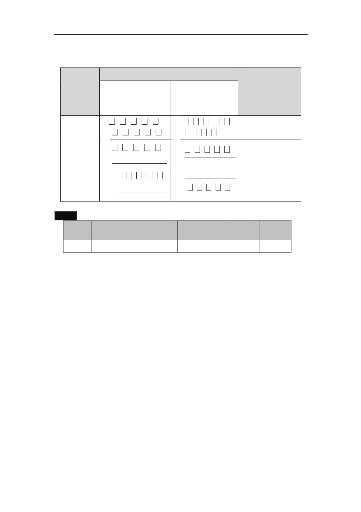
Table 7.5 Command pulse
pulse
Command Pulse
Input Mode
Signal
(movement
input pin
Forward
Reverse
parameter PA-22)
Setting
A
A
0 (positive pulse)
B
B
CP
XS4-14
CP
CP
XS4-15
1 (pulse +
DIR
DIR
DIR
direction)
XS4-16
CW
CW
XS4-17
CCW
ccw
2˄CW+CCW˅
˄CW+CCW˅
PA--23
Default
NO.
Parameter
Scope
Unit
value
PA--23
Selection of control mode
0̚7
0
Function and setting:
This parameter is used to select control mode for the Servo Amplifier.
z
0: indicates the C-axis position control mode, receiving the position pulse input
command.
z
1: indicates the external speed control mode, receiving speed analog input
command.
z
2: indicates the external speed control mode, receiving speed pulse input
command.
z
3: indicates the internal speed control mode. The internal speed command is set
by movement parameter PA-20.
z
4˖Multi-speed mode
z
7˖Motor encoder Zero calibration mode
134
PA--29
Default
NO.
Parameter
Scope
Unit
value
The second position
1̚32767
1
PA--29
command pulse frequency
molecular
Function and setting:
1ǃ Set the second position command pulse frequency molecular
2ǃ This parameter is valid when STA-13 is 1DŽ
PA--30
Default
NO.
Parameter
Scope
Unit
value
The third position
1̚32767
1
PA--30
command pulse frequency
molecular
Function and setting:
1ǃ Set the third position command pulse frequency molecular
PA--33
Default
NO.
Parameter
Scope
Unit
value
Position forward filter time
0̚3000
0
ms
PA--33
constant
Function and setting:
1ǃ Set position forward filter time constant.
2ǃ The smaller the time constant, the faster of response characteristics of the control
system, make the system unstable, oscillation.
PA--35
Default
NO.
Parameter
Scope
Unit
value
Position command
0̚3000
1
PA--35
smoothing time
Function and setting:
1ǃ Set position command smoothing time.
135
2ǃ The smaller the time constant, the faster of response characteristics of the control
system.
3ǃ The larger the filter time constant, the slower response of the control system, this
parameter is usually set to 0.
PA--39
Default
NO.
Parameter
Scope
Unit
value
The fourth position
1̚32767
1
PA--39
command pulse frequency
molecular
Function and setting:
1ǃ Set the fourth position command pulse frequency molecular.
7.2.5 Parameters Related to Speed Control Mode
Table 7.6 Parameters related to speed control mode
NO.
Parameter
Function
Value Range
1.Set parameters to the proportional gain for the
speed regulator.
2.Gain and rigidity will be enhanced as the
parameter value increases. This parameter is
Speed
determined by the actual Servo Amplifier system
PA--2
proportional
type and the load. Generally, load inertia grows
20̚10000
gain 1
as the value increases.
3.It is recommended that the value be larger if no
oscillation exists.
4.this parameter will be automatically adjusted
after setting PA 43 .
1.Set this parameter to the speed regulator
integration time constant.
2.Integration speeds up as the value decreases.
This parameter is determined by the actual Servo
Speed
Amplifier system type and the load. Generally,
PA--3
integral time
5̚500mS
load inertia grows as the value increases.
constant 1
3.It is recommended that the value be smaller if
no oscillation exists.
4.this parameter will be automatically adjusted
after setting PA 43 .
136

1.Set this parameter to the features of low-pass
filter for speed feedback.
2.Noise produced by motors and cut-off
frequency decreases as the value increases. If the
Speed
load inertia is large, decrease the value to prevent
PA--4
feedback
0 ̚ 9
from slow response or oscillation.
filter factor
3.The cut-off frequency increases and speed
feedback response becomes faster as the value
decreases. If high speed feedback response
required, decrease the value.
Deceleration
1. The value indicates the time required for
PA--38
time
motor slow down from the 1000 speed to 0r/min.
1̚32000
constant
2. Deceleration features linearity.
Acceleration
1. The value indicates time required for motor
PA--6
time
speed up from 0 r/min to 1000 speed.
1̚32000
constant
2. Acceleration features linearity.
1.Set this parameter to the relationship between
voltage and rotary speed under analogue speed
Analogue
command mode.
speed
PA--7
0̚6000
2.The value is the speed corresponding to the +
command
10 V voltage ( unit: 1 r/min)
input gain
3.The valve is effective under the external speed
control mode.
1. In the speed control mode, this parameter is
used to adjust zero drift input by external
Speed
analogue speed command. The method of
command
adjustment is as follows:
PA--8
zero drift
-1023̚+1023
z Perform short-connection between the
compensatio
analogue control input terminal and
n
grounding wire for signal.
z Set this parameter to the value that stops the
operation of the motor.
1. Set parameters to the internal speed when
-32000̚
PA--23=3.
PA-20
Internal
32000 (unit˖
2. In the internal control mode, select the internal
speed
1r/min)
speed as the speed command.
JOG
1. Set this parameter to the speed in the JOG
0̚2000
PA-21
operating
mode.
(unit˖1r/min)
speed
137
4. This parameter is used to select the control
mode for Servo Amplifier.
z
0: Position control mode, receiving
computer position command pulse.
z
1: indicates the external speed control mode,
Selection of
receiving speed analog input command.
PA-23
control
z
2: indicates the external speed control mode,
0̚7
mode
receiving speed pulse input command.
z
3: indicates the internal speed control mode.
The internal speed command is set by
movement parameter PA-20.
z
4: multi speed mode
z
7: the motor encoder zero mode
1. Set parameters to speed reached.
1̚500r/min
speed
2. In the speed control mode, if the motor speed
PA-42
reached
is less than the set value, the rate reaches the
range
switch signal to ON, otherwise OFF
7.2.6 Parameters Related to Output Torque Regulation
PA--5
Default
NO.
Parameter
Scope
Unit
value
Maximum torque output
30̚500
250
1%
PA--5
rate
Function and setting:
1ǃ Set the maximum torque output rate.
2ǃ The value represents the maximum output torque is multiple of the motor torque
3ǃ Any time ,this limitation is effective.
4ǃ 30~ 500 means the set range: 0.3~ 5 times of the rated torque.
5ǃ This parameter will be corresponding adjusted according to PA—43.
PA--9
Default
NO.
Parameter
Scope
Unit
value
Torque command input
PA--9
80̚32000
20000
gain
Function and setting:
1ǃSet the relationship of voltage and torque of external analog torque command.
2ǃOnly in the torque control mode (PA--23=2) effectively.
138
PA--10
Default
NO.
Parameter
Scope
Unit
value
Torque command zero
-1023̚
PA--10
0
drift compensation
+1023
Function and setting:
ǃ In the torque control mode (PA--23=2), adjust the zero drift. of external analog
torque
ǃ Adjustment methods are as follows:
The external analog input terminal and the signal ground short circuit, set the
parameters until the motor does not turn.
PA—15/PA--16
Default
NO.
Parameter
Scope
Unit
value
Positive maximum torque
PA--15
0̚500
280
1%
output rate
Negative maximum torque
PA--16
-500̚0
-280
1%
output rate
Function and setting:
ǃ Set the internal torque limiting value in the CCW/CW direction of the servo
ǃ The value is the desired positive /negative maximum output torque.
ǃ When STA10 is set to 1, the two limit are effective.
ǃ If PA--15>PA 5(or |PA--16| >PA--5), the actual output rate is restricted to a
maximum torque output rate permitted by PA—5.
ǃ The corresponding range: 0~ 5 times of the positive /negative output torque.
ǃ PA--15 PA--5˗|PA--16| PA—5.
PA--18
Default
NO.
Parameter
Scope
Unit
value
PA--18
overload torque
30̚200
120
1%
Function and setting:
ǃ Set the system overload torque.
ǃ Any time, this limitation is effective.
ǃ 30̚200 means the set range: 0.3̚2times of overload torque.
ǃ PA--18 PA—5.
ǃ The parameter will be automatically adjusted after PA—43 set
139
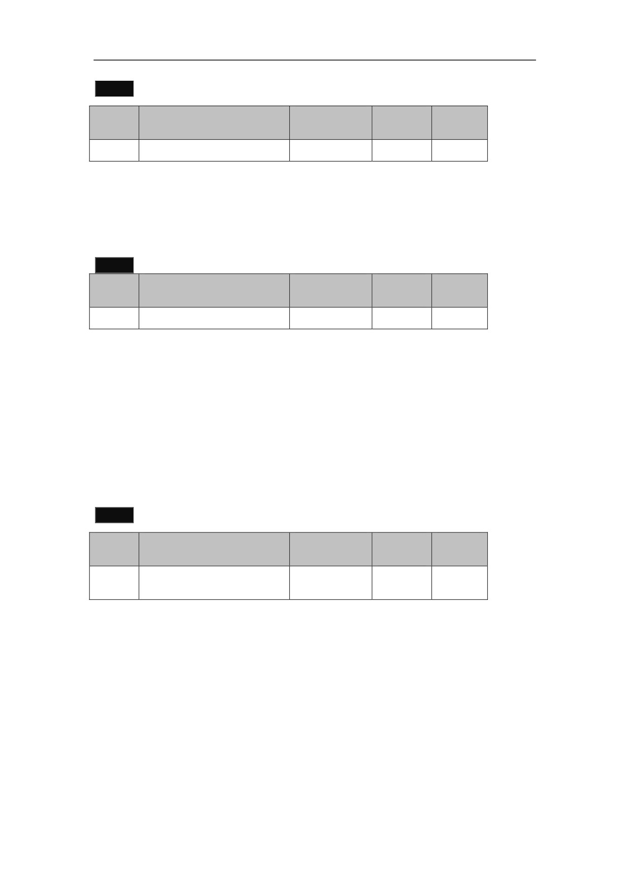
PA--19
Default
NO.
Parameter
Scope
Unit
value
PA--19
Overload time
40̚32000
1000
10ms
Function and setting:
1. Set this parameter to the allowable overloading time of the system.
2. The value indicates the overloading time per time unit (unit: 0.1s). For example, if
the value is 1000, the allowable overloading time is 10s.
3.The value is effective at any time.
PA--23
Default
NO.
Parameter
Scope
Unit
value
PA--23
Control mode selection
0̚7
0
Function and setting:
z
0: Position control mode, receiving computer position command pulse.
z
1: indicates the external speed control mode, receiving speed analog input
command.
z
2: indicates the external speed control mode, receiving speed pulse input
command.
z
3: indicates the internal speed control mode. The internal speed command is set
by movement parameter PA-20.
z
4: multi speed mode
z
7: the motor encoder zero mode
PA--27
Default
NO.
Parameter
Scope
Unit
value
Current control
PA--27
10̚32767
2600
proportional gain
Function and setting:
1ǃ Set this parameter to the proportional gain of current loop.
2ǃ Decrease the value to decrease the loud noise of current during motor operation.
3ǃ However, a small value will decrease the feedback response.
140
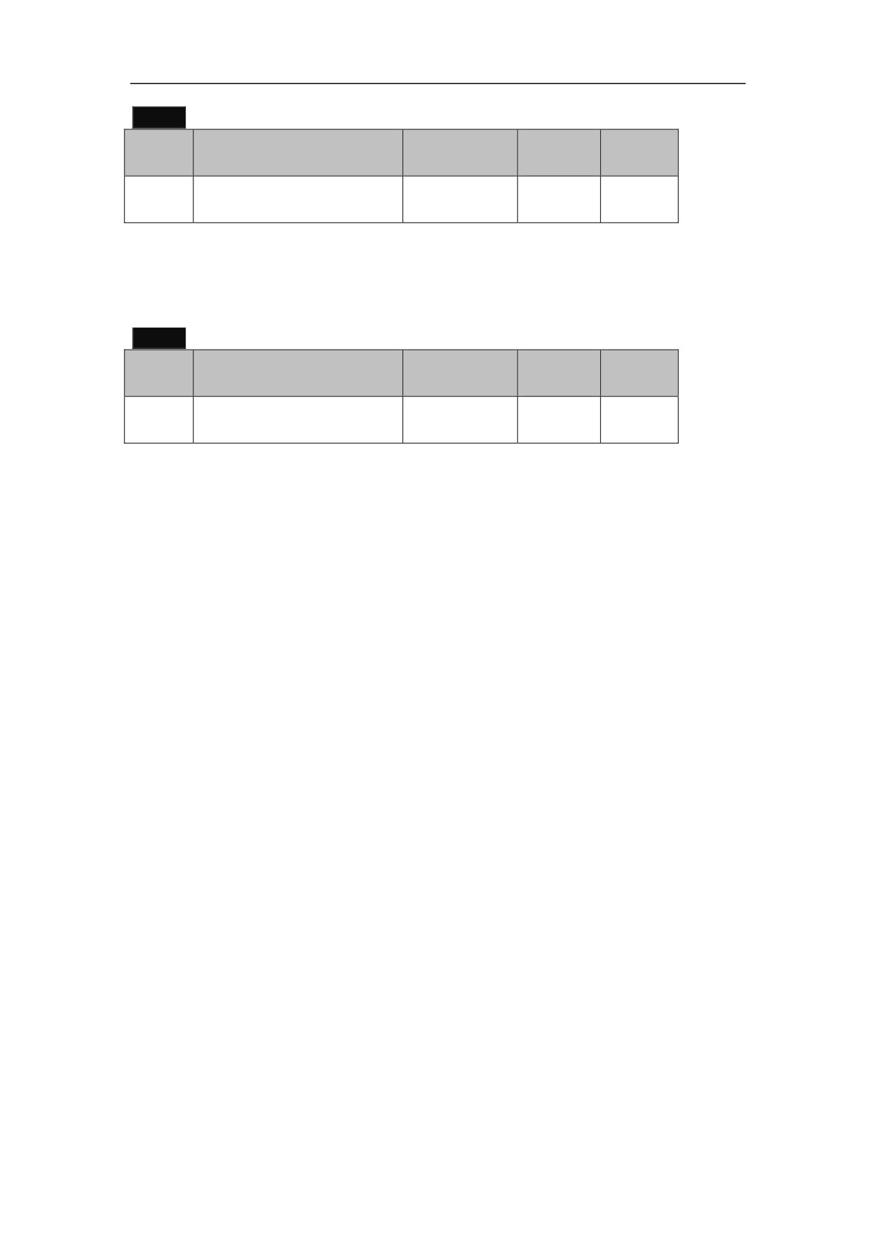
PA--28
Default
NO.
Parameter
Scope
Unit
value
Current control integration
PA--28
10̚32767
2600
time
Function and setting:
1. Set this parameter to the integration time of current loop.
2. Increase the value to decrease the loud noise of current during motor operation.
3. A big value will decrease the feedback response.
PA--32
Default
NO.
Parameter
Scope
Unit
value
Torque command filter
0̚500
0
0.1ms
PA--32
time constant
Function and setting:
ǃ Set the Torque command filter time constant.
ǃ The greater of the time constant, the slower of response of the control system. it
will make the system unstable, oscillation.
7.2.7 Non standard motor parameter settings
Select HSV-180AD series Servo Amplifier , refer to table7.3.
If the code cannot be found in Table 7.3, or use other manufacturers IM servo
motor, you must manually set the operating parameters. Details as follows:
1. Confirm whether the servo motor specifications match with the Servo
Amplifier specifications
2. Confirm whether the Servo Amplifier is installed to support the servo motor
encoder.
3. Setting parameters according to the type of IM servo motor:
Setting PA--34 to 2003
Setting PA--43 according to the type of servo motor
HSV-180AD-035˖Setting PA—59 to 1
HSV-180AD-050˖Setting PA—59 to 102
HSV-180AD-075˖Setting PA—59 to 203
HSV-180AD-100˖Setting PA—59 to 304
HSV-180AD-150˖Setting PA—59 to 405
According to the actual requirement, set PA—17, PA—24, PA—25, PA--26,
PB--42and PB--43
4. Setting PA--34 to 1230, saving parameters in the secondary menu , and restart
the Servo Amplifier.
5. Confirmation weather phase sequence of the servo motor is correct.
6. The Servo Amplifier access systems up to running after confirmation.
141
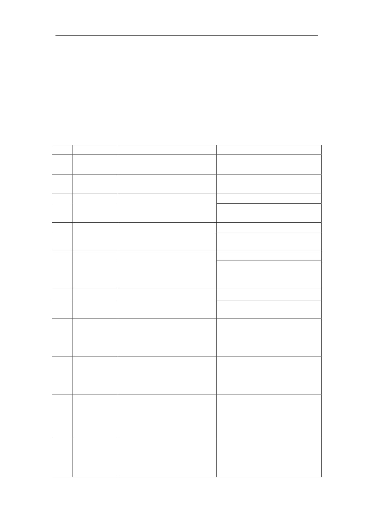
7.3 Control Parameter Mode
Series HSV-180AD Servo Amplifier provides 16 control parameters, see Table
7-6,7-7. For the parameter operation, setting, modifying and saving.
7.3.1 Control Parameter
Table 7-6 Control Parameters(state control number is 1 )
NO.
Parameter
Function
Description
Position command interface
0˖Serial pulse
0
STA-0
selection
1˖NCUC
1
STA-1
Reserved
This parameter is used to
0: Allow
2
STA-2
specify whether feedback
1: Not allow
break-off alarm is allowed.
This parameter is used to
0: Allow
3
STA-3
specify whether system
1: Not allow
overspeed alarm is allowed.
This parameter is used to
0: Allow
specify whether position
4
STA-4
over-tolerance alarm is
1: Not allow
allowed.
This parameter is used to
0: Allow
5
STA-5
specify whether Software
1: Not allow
overheating alarm is allowed.
This parameter is used to
specify whether the internal
1: Internal enable
6
STA-6
SVR-ON control start is
0: External enable
allowed.
This parameter is used to
specify whether system main
1: Not allow
7
STA-7
power undervoltage alarm is
0: Allow
allowed.
This parameter is used to
specify whether the forward
1˖Allow
8
STA-8
over travel switch input is
0˖Not allow
allowed.
This parameter is used to
specify whether the reverse
1˖Allow
9
STA-9
over travel switch input is
0˖Not allow
allowed.
142
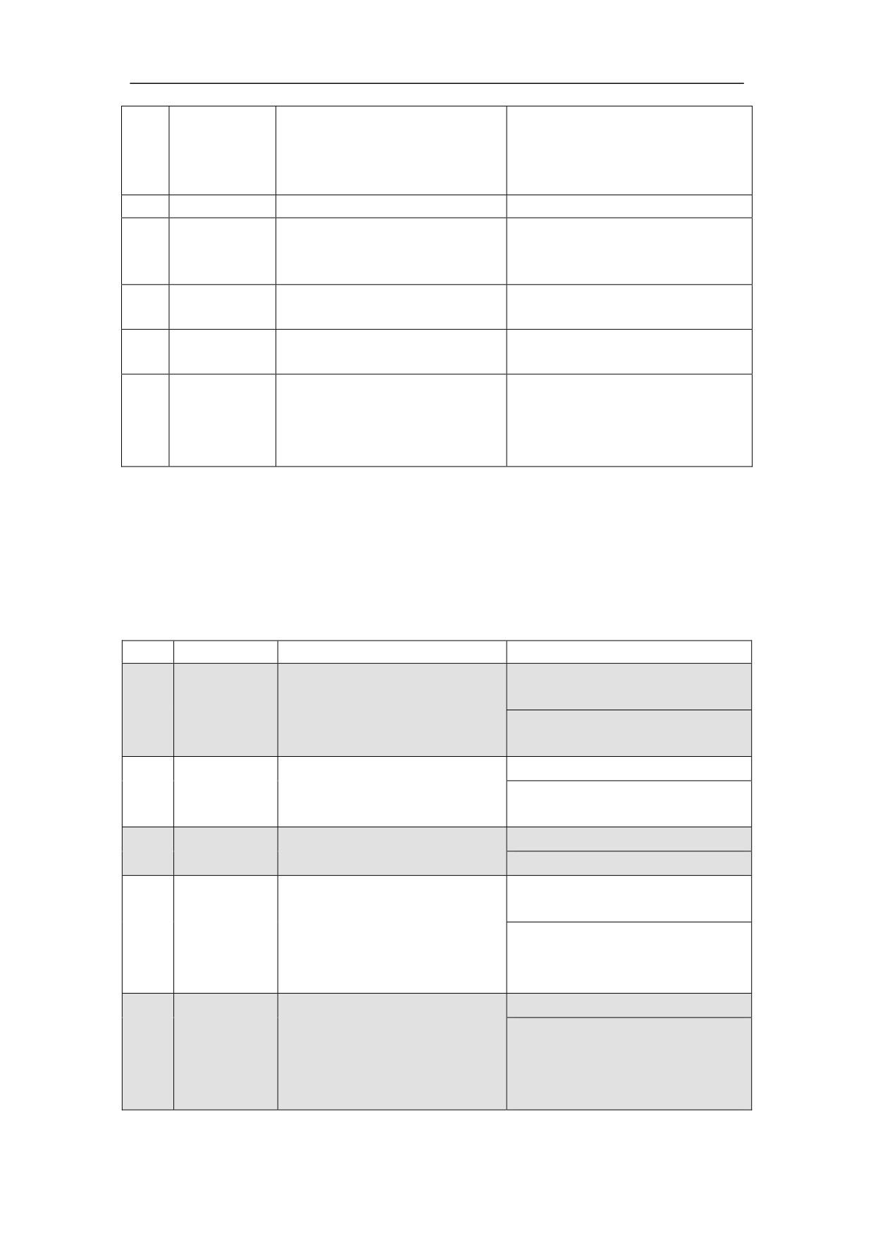
This parameter is used to
specify whether positive and
1˖Allow
10
STA-10
negative torque limit is
0˖Not allow
allowed.
11
STA-11
Reserved
This parameter is used to
1: Not allow
12
STA-12
specify whether motor
0: Allow
overheat alarm is allowed.
Electronic gear ratio dynamic
1: Not allow
13
STA-13
switching selection
0: Allow
1: Not allow
14
STA-14
Gain switching enable.
0: Allow
This parameter is used to
specify whether the Servo
1: Not allow
15
STA-15
Amplifier overheat alarm is
0: Allow
allowed.
7.3.2 Extended control parameters
Set PA—34to2003 in the motion parameters, could open the extension control
parameter mode. HSV-180AD have a total of 16 extended control parameters of STB
Figure 7-7 Description of the extended control parameters
˄State control word 2˅
NO.
Parameter
Function
Description
0˖The position pulse from the
computer
0
STB-0
Command pulse source
1˖The position pulse from the
internal PA--20
0: Not allowed
1
STB-1
Zero speed switch enable
1: Allowed
Whether the output Z pulse
0˖No expansion
2
STB-2
width is expanded
1˖Expansion
0˖The position tracking error
is less than the limit value
Complete positioning output
3
STB-3
1˖No position command input
mode selection
and the position tracking error
is less than the limit value
0˖Select PA—13andPA--14
1˖Select PB—4 command
The electronic gear function
4
STB-4
pulse corresponding feedback
selection
number calculation of electronic
gear ratio
143
Speed adaptive feature
0˖Not select
5
STB-5
selection
1: Select
6
STB-6
Reserved
0˖Low pass filter
7
STB-7
Position filter selection
1˖Smoothing filter
0: Not allowed
Whether the emergency stop
8
STB-8
1: Allowed
function is allowed
0˖General servo motor
9
STB-9
Torque motor mode selection
1˖Torque servo motor
0˖Incremental encoder output
Pulse frequency divider
directly
10
STB-10
output mode enable
1˖Digital encoder output
frequently
Speed feedback filter
0˖First order low pass filter
11
STB-11
selection
1˖Second order low pass filter
Incremental encoder
feedbackSTB-13 = 0 STB-12
= 0˖
Full closed loop position
ENDAT absolute encoder
12
STB-12
feedback signal selection
feedbackSTB-13 = 1 STB-12
13
STB-13
= 0˖
Sine cosine 1Vpp analog signal
feedback˖STB-13 = 1
STB-12 = 1˖
0: Not allowed
Full closed loop position
14
STB-14
control enable
1: Allowe
0˖Do not lock the operation
Lock control of the operation
keys
15
STB-15
keys
1˖Lock keys
˄Unlock:SET+MODE˅
144
8. Operation and Modification
Caution
z The Servo Amplifier and motor must be reliably grounded, and PE
terminal must be connected with the grounded terminal of the
equipment reliably.
z The power can be connected only after the wiring is correct.
z Emergency stop circuit must be provided to make sure the power could
be stopped at once in case of emergency.
z If a Servo Amplifier alarm is reported, make sure the alarm is cleared
and the servo enable input signal (EN) is ineffective before restarting
the Servo Amplifier.
z After the Servo Amplifier and motor are power off, do not touch the
Servo Amplifier within 5 minutes to avoid electronic shock.
z Be cautious to prevent burning as the temperature may get higher after
the Servo Amplifier and motor running for a period of time.
8.1 Power Connection
8.1.1 Checking Before Running
After the installation and connection is completed, check the following items
before power on:
z
Whether the type of Servo Amplifier HSV-180AD-200 and above is
correct and reliable? Whether the input voltage is correct?
z
Whether the strong power terminal (L1ǃL2ǃL3ǃUǃVǃWǃPǃ
BKǃPE) is correct and reliable? Whether the input voltage is correct?
z
Whether the power lines or motor lines is short circuited or grounded.
z
Whether the encoder cable connection is correct?
z
Whether the control signal terminal connection is correct? Whether the
polarity and size are proper?
145
z
Whether the Servo Amplifier and motor are fixed firmly?
8.1.2 Power On Sequence
z
For HSV-180AD-035ˈ050ˈ075ˈ100ˈ150,connect the main circuit power
(three-phase AC380V) and external DC 24V power supply. The digital tube of
the Servo Amplifier is light, servo alarm (ALM) is disconnected, and the failure
chain relay normally-open contact on interface XS5 closed. If an alarm is
reported, power the Servo Amplifier off and check the trouble.
z
For HSV-180AD-200ˈ300ˈ450, connect the Servo Amplifier control power
(single-phase AC380V) and external DC 24V power supply. The digital tube of
the Servo Amplifier is light, servo alarm (ALM) is disconnected, and the failure
chain relay normally-open contact on interface XS5 closed. If an alarm is
reported, power the Servo Amplifier off and check the trouble. If an alarm is not
appear, connect the main circuit power (three-phase AC380V)
z
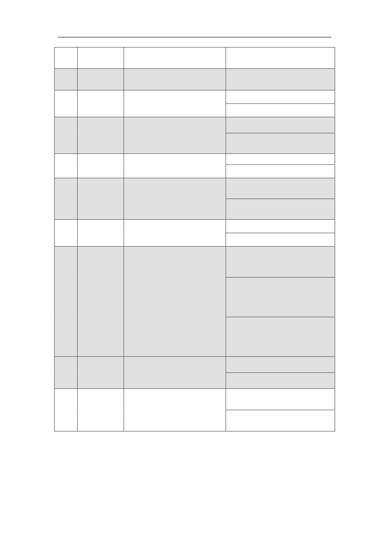
After 1 second, the servo enable signal (EN) is received. If the Servo Amplifier
have no faults and the servo enabling function is effective, the motor is activated
and in the state for running. If an alarm is reported and the servo enabling
function is ineffective, the motor is idle. At this time, power off the main circuit
power and check the trouble.
z
In the external speed running mode (analog interface), the PC outputs the servo
forward (FWD) or servo reverse (REW) control signal to Servo Amplifier. And
operate PC to send analog command to Servo Amplifier. The motor runs
according to the command.
z
In the position running mode (pulse interface) or the external speed running mode
(pulse interface), the PC to send pulse command to Servo Amplifier. The motor
runs according to the command.
8.1.3 power connection and alarm sequence
Figure 8-1 HSV-180AD-035ˈ050ˈ075ˈ100ˈ150 Sequential diagram for
power connection (analog command)
146
Main circuit power
supply
Servo ready
output
Servo enable input
Analog command
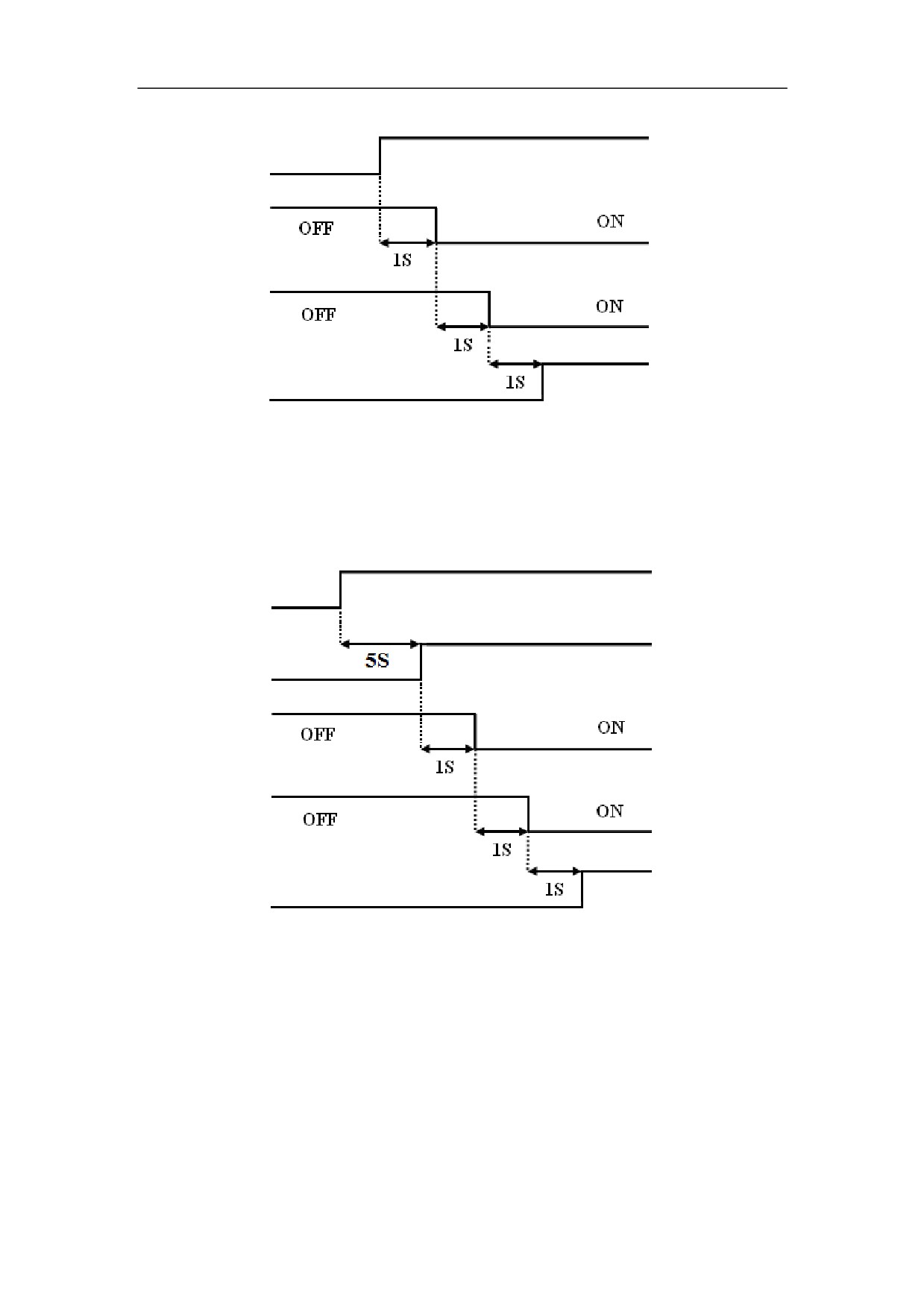
Figure 8-1 HSV-180AD-035ˈ050ˈ075ˈ100ˈ150Sequential diagram for
power connection (analog command)
Control power
Main circuit power
supply
Servo ready
output
Servo enable input
Analog command
Figure 8-2 HSV-180AD-200ˈ300ˈ450 Sequential diagram for power
connection (pulse command)
147
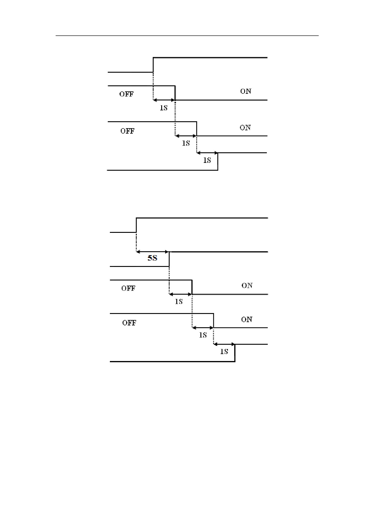
Main circuit power
supply
Servo ready
output
Servo enable input
Pulse command
Figure 8-3 HSV-180AD-035ˈ050ˈ075ˈ100ˈ150 Sequential diagram for
power connection (pulse command)
Control power
Main circuit power
supply
Servo ready
outputt
Servo enable input
Pulse command
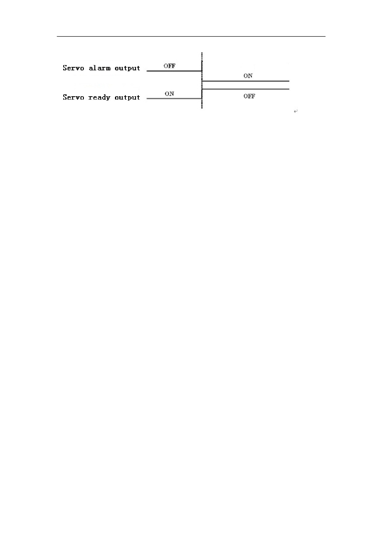
Figure 8-4 HSV-180AD-200ˈ300ˈ450Sequential diagram for alarming
Figure 8-5 Time sequence alarm
When a Servo Amplifier alarm is reported, cut off the external control circuit
power immediately based on the servo alarm output signal (ALM) or the failure
chain input/output terminal XS5.
148
8.1.4 Power Off Sequence
z
For HSV-180AD-035ˈ050ˈ075ˈ100ˈ150ˈdisconnect the main circuit
power (three-phase AC380V) of the Servo Amplifier. If the servo enable signal
(EN) keep outputting "ON" signal, A-1 (indicates main power low-voltage) is
displayed, the green enable light (EN) on the Servo Amplifier panel is off, and
the red alarm light (AL) is on (indicates alarm).
z
For HSV-180AD-200ˈ300ˈ450ˈfirstly disconnect the main circuit power
(three-phase AC380V) of the Servo Amplifier, and then disconnect the Servo
Amplifier control power (single-phase AC380V) and external DC 24V power
supply. When servo detect heavy electricity disconnected, if the servo enable
signal (EN) keep outputting "ON" signal, A-1 (indicates main power low-voltage)
is displayed, the green enable light (EN) on the Servo Amplifier panel is off, and
the red alarm light (AL) is on (indicates alarm).
z
After disconnect the main circuit power, the internal capacitor storage energy of
the Servo Amplifier could not be released immediately. Do not connect nor
disconnect wire within five minutes.
z
Avoid frequently turning on and off the main circuit power in a short period of
time, which may damage the soft-start circuit.
8.1.5. Alarm Clear
There are three methods to clear the alarm:
z Turn off the power (three-phase main power), after the fault source is cleared;
repower the Servo Amplifier to clear the alarm. (Some alarm can only be cleared
by this method).
149