Series HSV-180AD AC Servo Amplifier. User's Manual (V1.00 2012.4) - page 5
5.8 Standard Wiring
Caution
U, V, W on XT2 must be connected to the motor windings in corresponding order
and cannot be reversed.
Cables and wires must be fixed and cannot be near the radiator of the Servo
Amplifier or motor. Otherwise, the insulation properties may be reduced due to
overheat.
In the Servo Amplifier, large-capacity of electrolytic capacitor exists, which leads
to the remaining of high voltage even after power off. Therefore, do not touch the
Servo Amplifier or motor within five minutes after the power off.
Terminals P, BK on XT2 are connected to the external braking resistor.
Terminal P and BK cannot be shorted. Otherwise it will damage the Servo
Amplifier.
“Shell” in the wiring diagram refers to the mental shell of the wiring plug. The
cable shield must be connected to the metal shell. First unravel the shield and
avoid twisting together. Then loop part of the shield and cut off the rest. Last
cover the looped shield with casing, and weld the exposed shield to the metal
shell.
Avoid too much solder to make sure the plug shield can be covered.
It will be better, if you use a metal cable clip to form a 360-degree access and
perform nearby grounded.
100
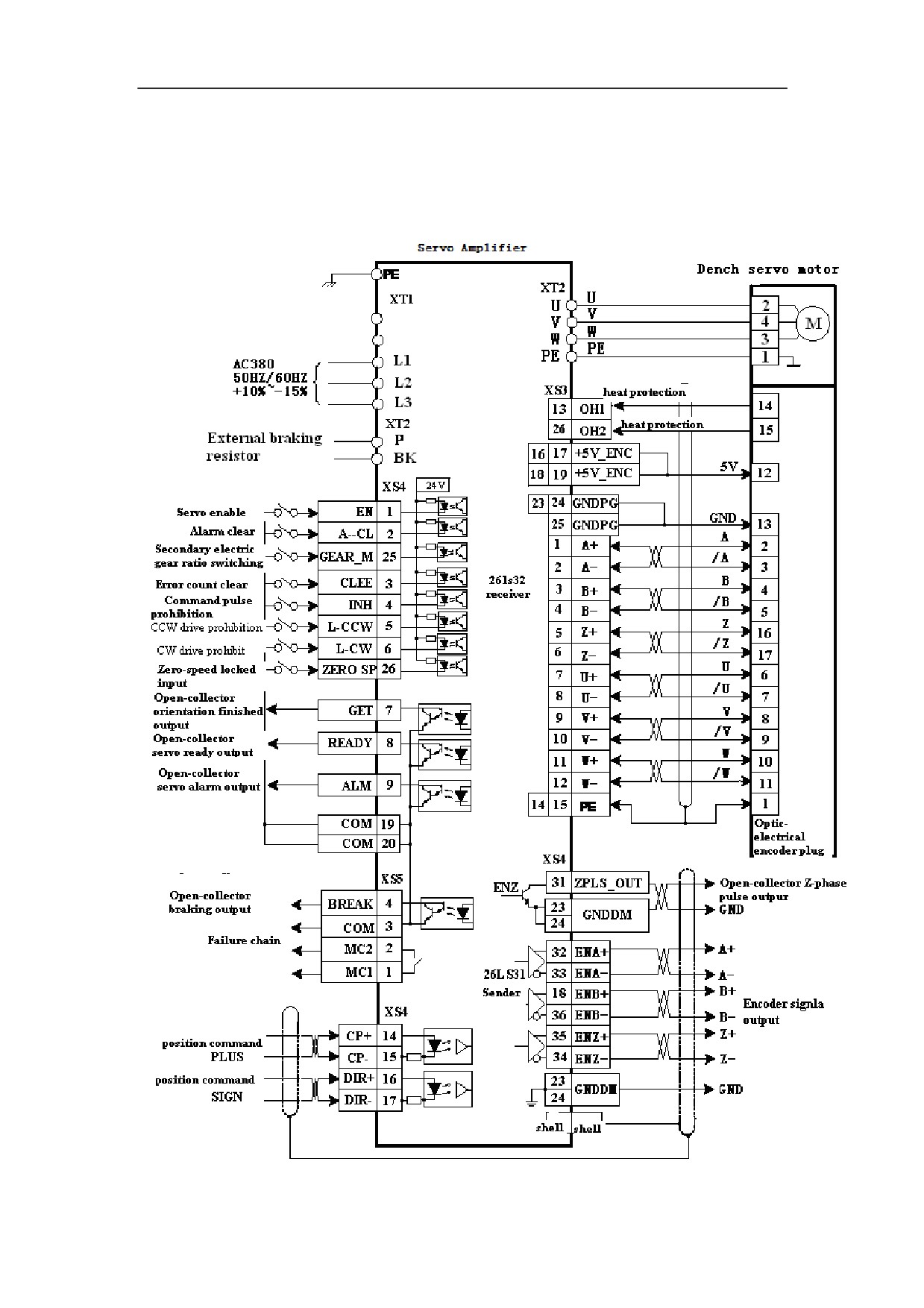
5.8.1 Standard Wiring for Position Control Mode (Pulse Interface)
Figure 5-44 Standard wiring for position control mode (pulse interface)
(Configured with Dench motor GK604, GK606, GK607, GK608, and GK610)
101
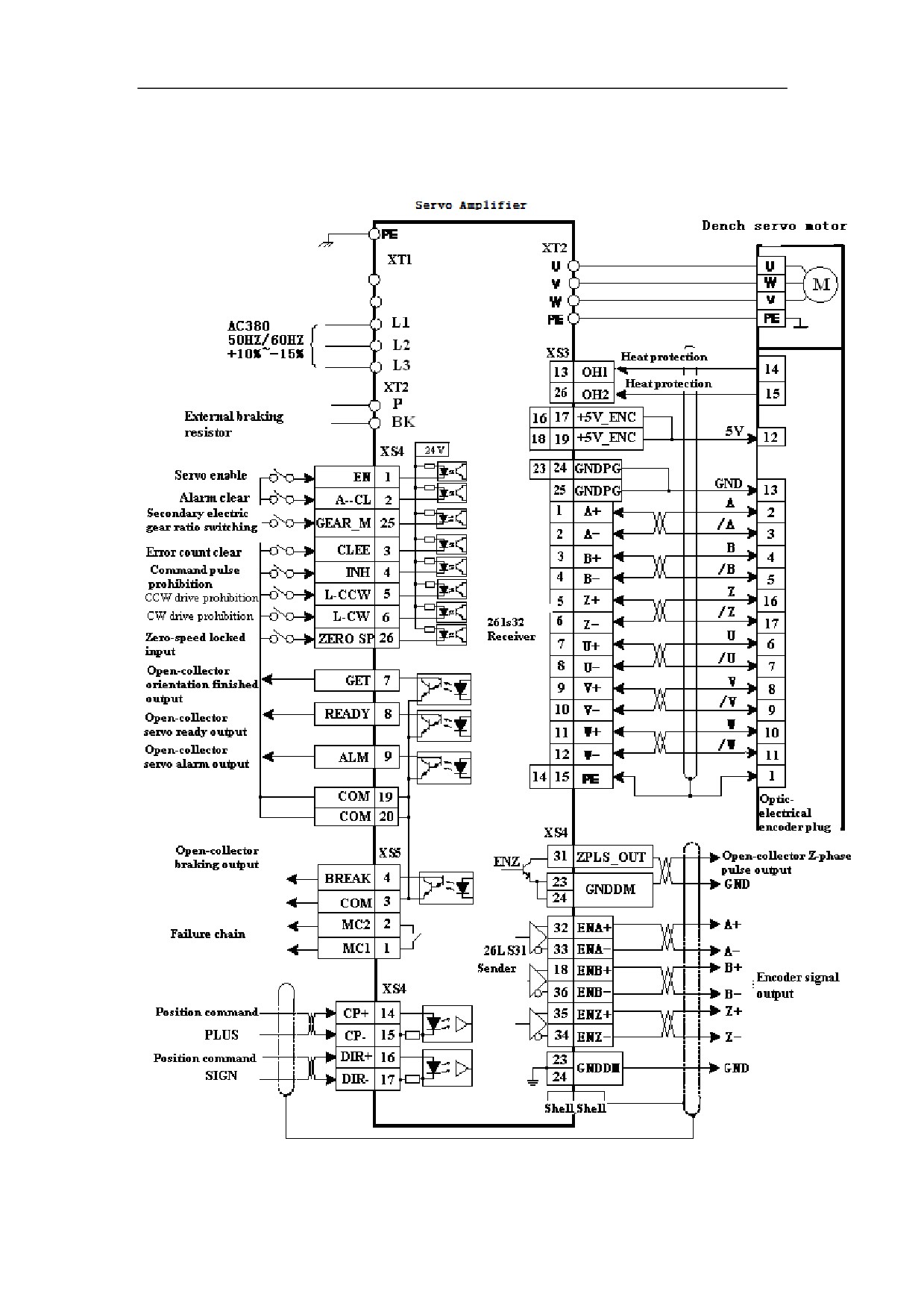
Figure 5-45Standard wiring for position control mode (pulse interface)
(Configured with Dench motor force coolingGK610, GK613 and GK618)
102
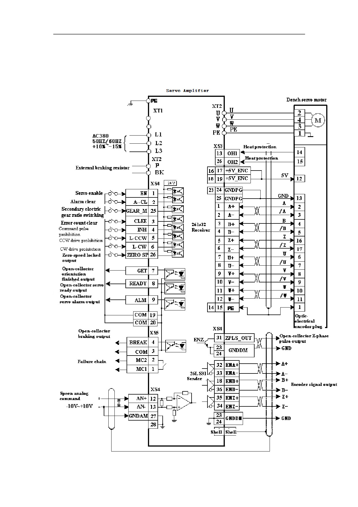
5.8.2 Standard Wiring for External Speed Control Mode (Analog
Interface)
Figure 5-46 Standard wiring for external speed control mode (analog interface)
(configured with Dench motor GK604, GK606, GK607, GK608, and GK610)
103
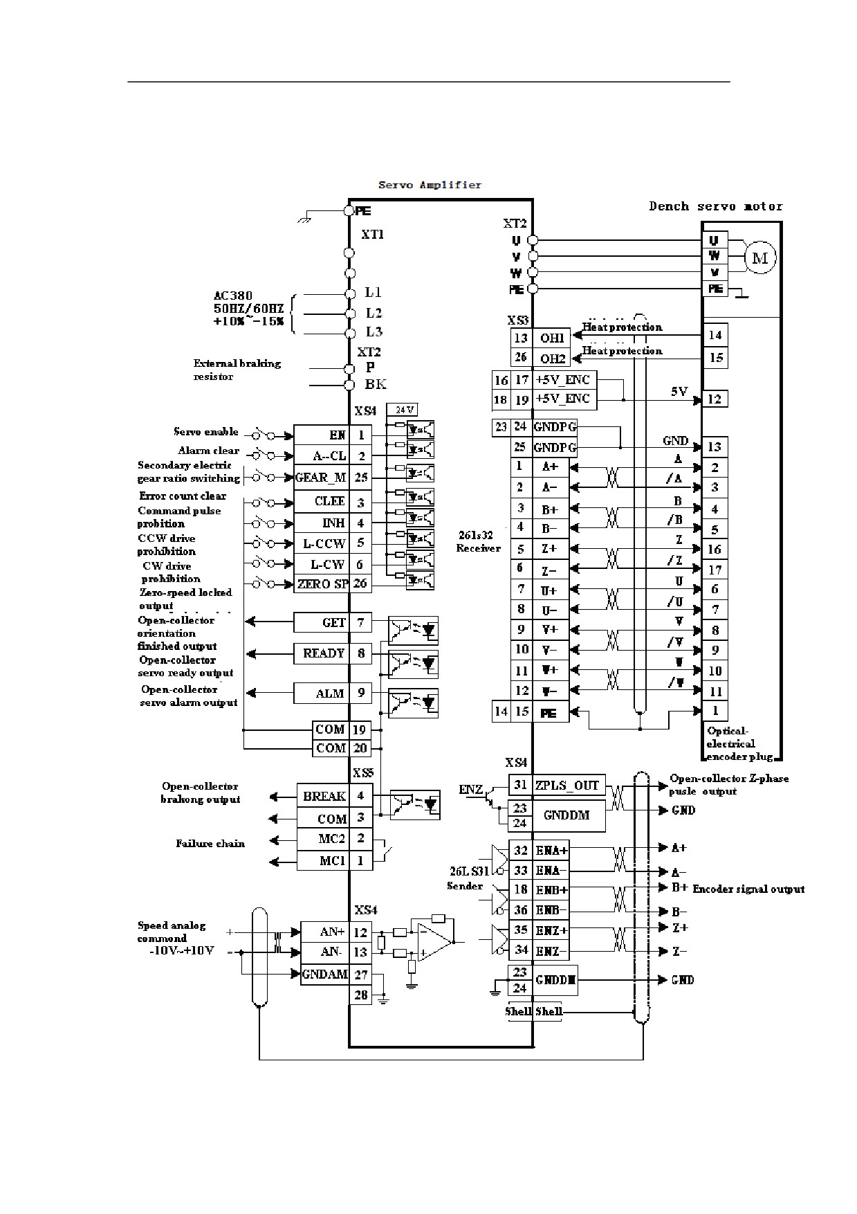
Figure 5-47 Standard wiring for external speed control mode (analog interface)
(Configured with Dench motor force coolingGK610, GK613 and GK618)
104
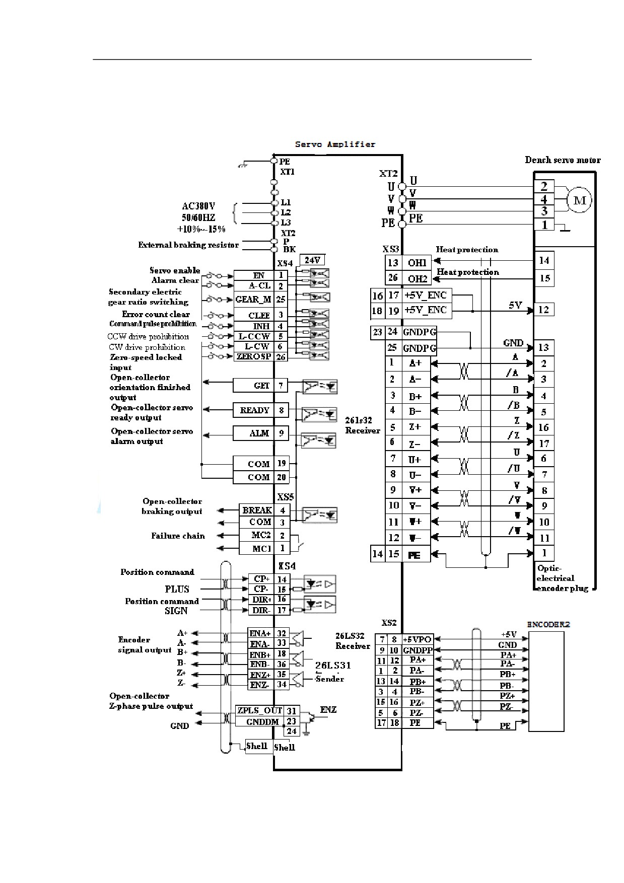
5.8.3 Standard Wiring for Closed-loop Control Mode (pulse interface)
Figure 5-48 Standard wiring for closed-loop control mode (pulse interface)
(configured with Dench motor GK604, GK606, GK607, GK608, and GK610)
105
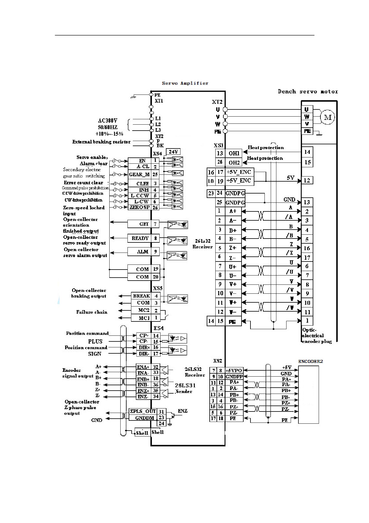
Figure 5-49 Standard wiring for closed-loop control mode (pulse interface)
(Configured with Dench motor force cooling GK610, GK613 and GK618)
106
6. Operation and Display
6.1 Overview
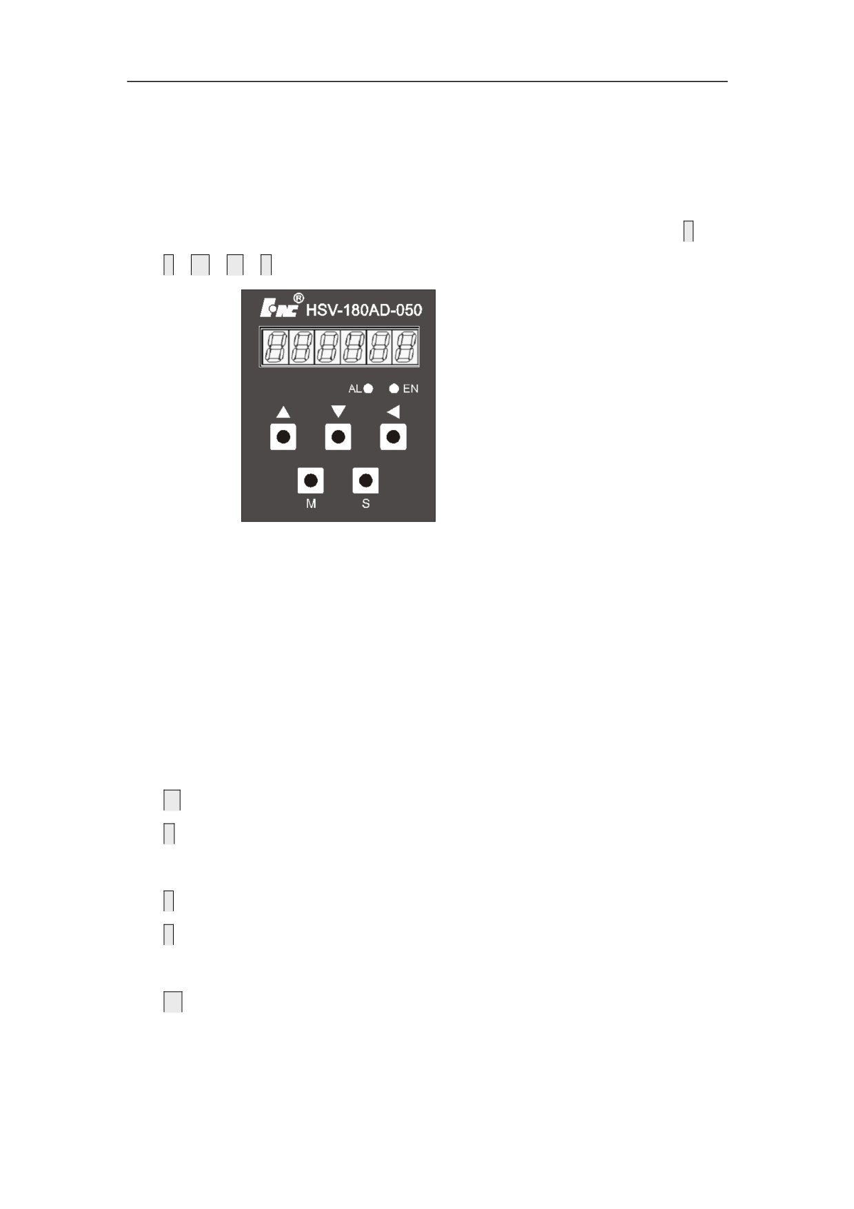
1. The Servo Amplifier panel consists of 6 LED digital displays, 5 buttons
Ĺǃ
Ļ
ǃ
ĸ
ǃ
M
ǃ
S, and 2 light-emitting diodes.
Figure 6-1 Digital display of series HSV-180AD Servo Amplifier
z The 6 LED digital displays are used to display various statuses and set
parameters.
z The red light-emitting diode is an alarming lamp (AL). When it is on, it
means " Servo Amplifier alarm". The green light-emitting diode is an enable
lamp (EN). When it is on, it means "Servo Amplifier enable"
z The function of each button is as follows:
M
˖used for main menu mode switching
S˖used for entering into the secondary menu, returning to the main menu
mode, and input confirmation
Ĺ
˖used for an increase in number and value, or moving to the next option
Ļ
˖used for a decrease in number and value, or moving back to the previous
option
ĸ
˖used for shifting
107
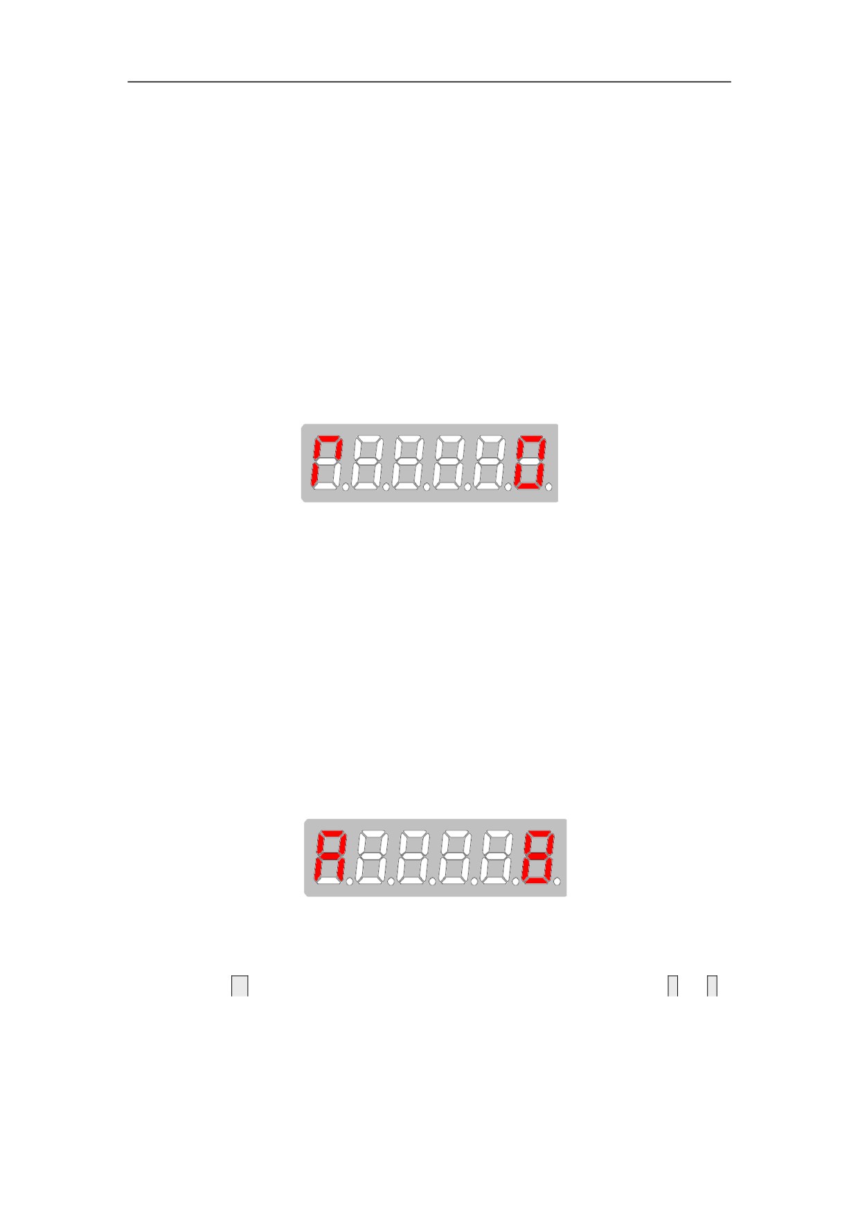
2. After the control power supply of the Servo Amplifier is connected, the six
LED digital displays on the panel all display "8", and change to "R O" a second
later.
3. Users must operate based on the multi-level menus. The first-level menu is the
main menu which includes five operation modes: display mode, movement
parameter mode, auxiliary mode, control parameter mode, and alarm history
display mode. Each operation mode contains a secondary menu.
Figure 6-2 R
0 display
4. The 6-bit LED digital tube displays various status and data of the system. If
the first bit of the digital tube displays A , and at the same time the red
light-emitting diode is on, an alarm is generated. The follow-up bit of the digital
tube displays the alarm code. After the process of fault diagnosis and
troubleshooting, you can reset the system by the alarm reset mode under the
auxiliary mode or cutting off the power and then re-power to the Servo Amplifier.
When the red light-emitting diode is off, the system is reset.
Figure 6.3 A8 Alarm display
6.2 Operation in the Display Mode
1. Press
M
to switch the operation mode on the main menu”, and press
Ĺ
and
Ļ
to enter the secondary menu for the display mode.
108
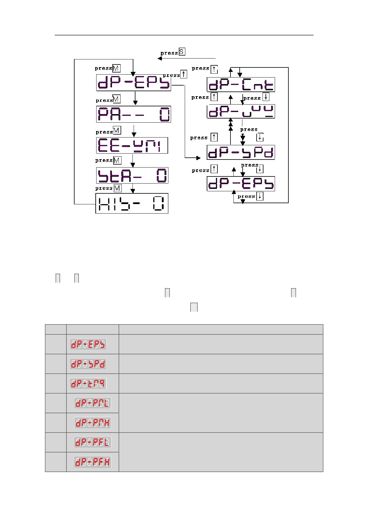
Figure 6-4 Main menu for the display mode
6.3 state surveillance mode
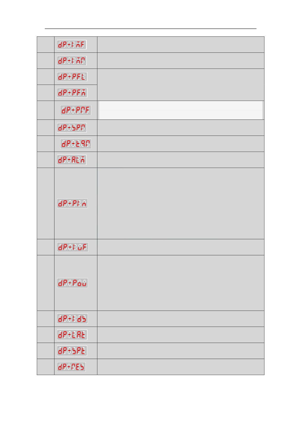
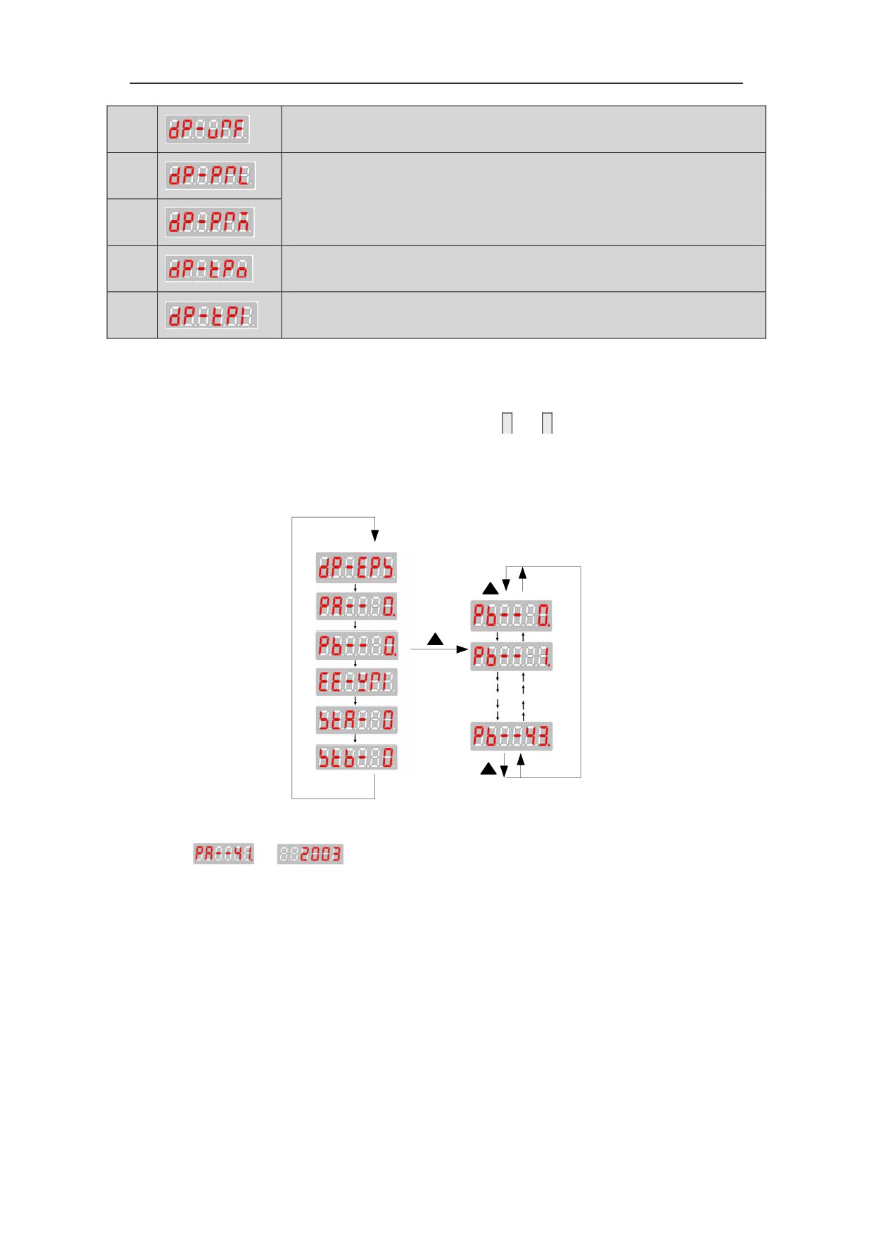
HSV-180AD Servo Amplifier contains 20 types of display modes(see table 6.1). Press
Ĺ
and
Ļ
to select a display mode as required. The display status can only be viewed
and cannot be modified or set. Press
S to display the detailed status, then press
S to
return to the secondary menu, and then press
M to return to the main menu.
Table 6-1 Meaning of each symbol in the display mode
NO.
Symbol
Description
Display the speed tracking error
1
unit˖pulse
2
Display the actual speed (unit: 0.1r/m)
Display the actual torque current˄Effective value ˅
3
unit˖0.1A
4
Display position command
unit˖pulse
5
Actual position = DP-PRM * 10000 + DP-PRL
6
Display the actual position of motor
unit˖pulse
7
Actual position = DP-PFM * 10000 + DP-PFL
109
Display the actual magnetic field current˄Effective value˅
4
unit˖0.1A
Display the magnetic field current command
5
unit˖0.1A
6
Display the actual position of motor
unit˖pulse
7
Actual position = DP-PFM * 10000 + DP-PFL
Display pulse frequency
8
unit˖0.1KHz
Display speed command
9
unit˖ 1r/min
Display magnetic current
10
unit˖0.1A
11
Display alarm status
Display switch-value input status
PIN.1˖Servo Amplifier enable
PIN.2˖alarm status reset
PIN.3˖CW control
12
PIN.4˖CCW control
PIN.5˖INC_Sel1
PIN.6˖INC_Sel2
PIN.7˖servo orientation control
PIN.8˖control mode switch
11
Display the actual feedback value of the U-phase current
Display switch-value output status
POU.1˖zero-speed reached
POU.2˖drive system ready
12
POU.3˖alarm output
POU.4˖reserved
POU.5˖speed reached
POU.6˖servo orientation-finished
Display the actual load current˄Effective value ˅
13
unit˖0.1A
Display the number of the feedback pulse of the servo motor
14
optic-electrical encoder
15
Display the number of feedback pulse of the servo encoder
16
Display the speed deviation
110
Display voltage reference output
17
18
Display position command
unit˖pulse
19
Actual position = DP-PRM * 10000 + DP-PRL
Display the single-turn absolute position value of Absolute
20
encoder
21
Reserved
6.4 Operation in the Movement Parameter Mode
1. On the main menu, select "PA--0", and press
Ĺ
and
Ļ
to enter the secondary
menu for the movement parameter mode.
2. Series HSV-180AD Servo Amplifier contains 44 movement parameters.
Figure 6-6 Secondary menu for the movement parameter mode
z
Set
to
ˈcould open extension movement parameter mode
HSV-180AD Servo Amplifier have 44 extension parameters
111
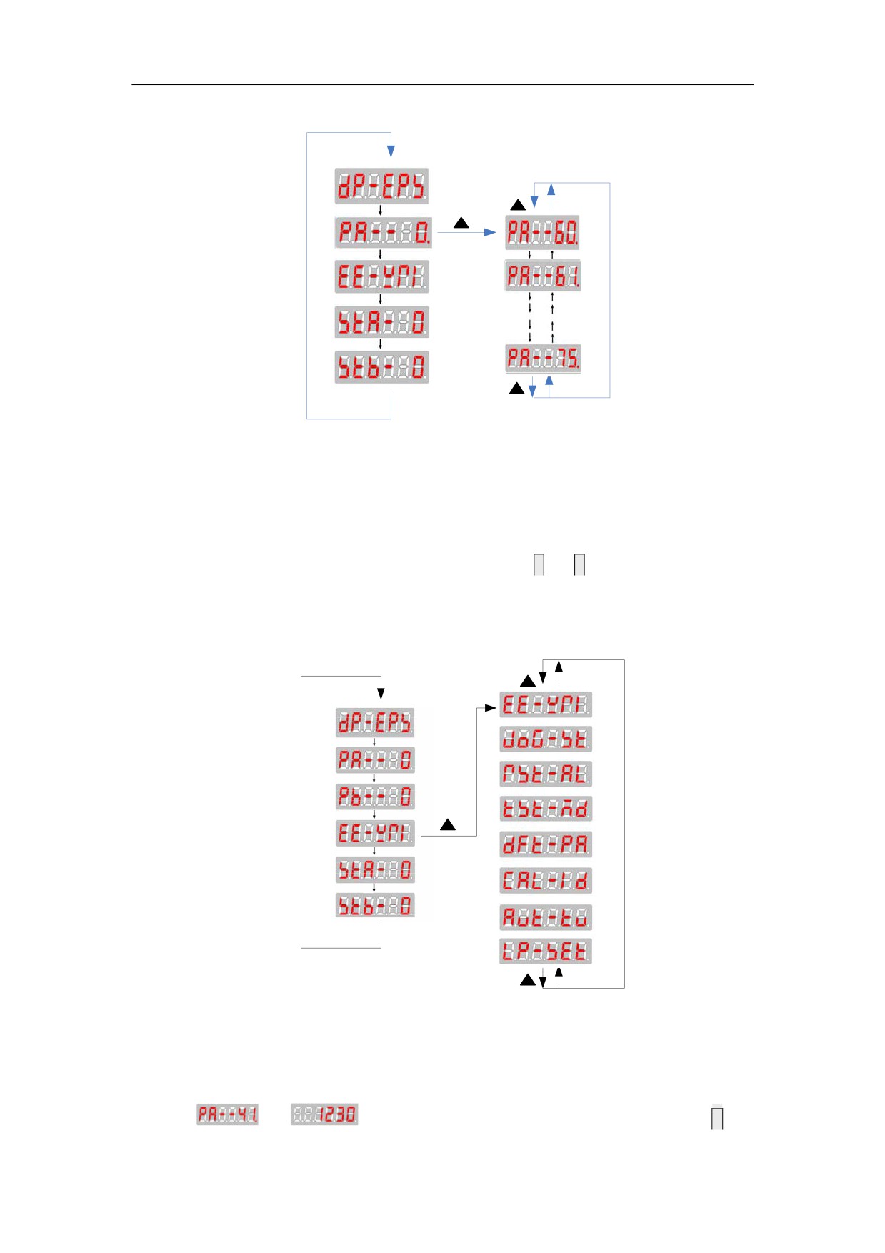
Figure 6-5 Secondary menu for extension movement parameter mode
6.5Operation in the Auxiliary Mode
1. On the main menu, select“EE-WRI”, and press
Ĺand
Ļ
to enter the secondary
menu for the auxiliary mode.
2. Series HSV-180AD Servo Amplifier contains 8 types of auxiliary modes
Figure 6-8 Secondary menu for the auxiliary mode
A. EEPROM mode: This method is effective only during the parameter
changes and settings. If changing or setting parameters, you should firstly set
to
, then save the new parameter values by pressing
S in
112
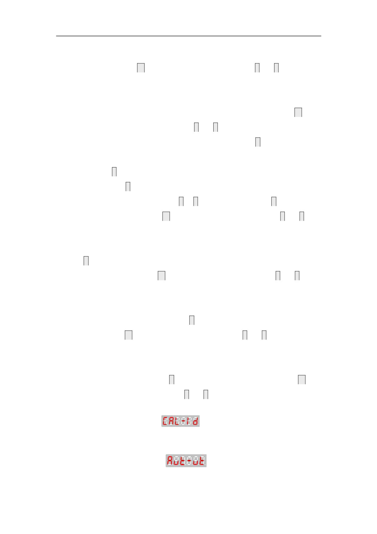
this mode. When “FINISH” is displayed, the parameter change and setting is
completed. Press
M
to switch to another mode, or press
Ĺ
and
Ļ
to select
other operations in the auxiliary mode.
B.
JOG mode: This mode is effective only in JOG running. When the JOG
speed parameter PA-21 is a non-zero value, on the main menu, press
M
to
select the auxiliary mode, and press
Ĺ and
Ļ
to select the JOG running mode.
“JOG---” is displayed through the digital display. Press
S, “R --- ”is
displayed, which indicates that the system enters into the running state. Press
and hold
Ĺ
, then the Servo Amplifier and motor run at the speed specified by
PA-21. Press
Ļ
, then the motor run at the speed specified by PA-21 in the
opposite direction. Release the
Ĺ
or
Ļ
to stop the motor. Press
S to return to
the auxiliary mode. Press
M to switch to another mode, or press
Ĺ
and
Ļ
to
select other operations in the auxiliary mode.
C.
Alarm resetting mode: When the Servo Amplifier generates an alarm, press
S to reset the system in this mode. If the fault is cleared, the Servo Amplifier
returns to normal. Press
M
to switch to another mode, or press
Ĺ
and
Ļ
to
select other operations in the auxiliary mode.
D.
Default restoration mode: This mode is used to set the parameters to the
default values. In this mode, press
S to restore system parameters to default
values. Press
M
to switch to another mode, or press
Ĺ
and
Ļ
to select other
operations in the auxiliary mode.
E.
Alarm history clearance mode: This mode is used to clear alarm history
records. In this mode, press
S
to clear the alarm history records. Press
M
to
switch to another mode, or press
Ĺ
and
Ļ
to select other operations in the
auxiliary mode.
FǃEncoder zero calibration
1 Auxiliary correct encoder zero calibration of the motor.
GǃParameter self-adjustment
113
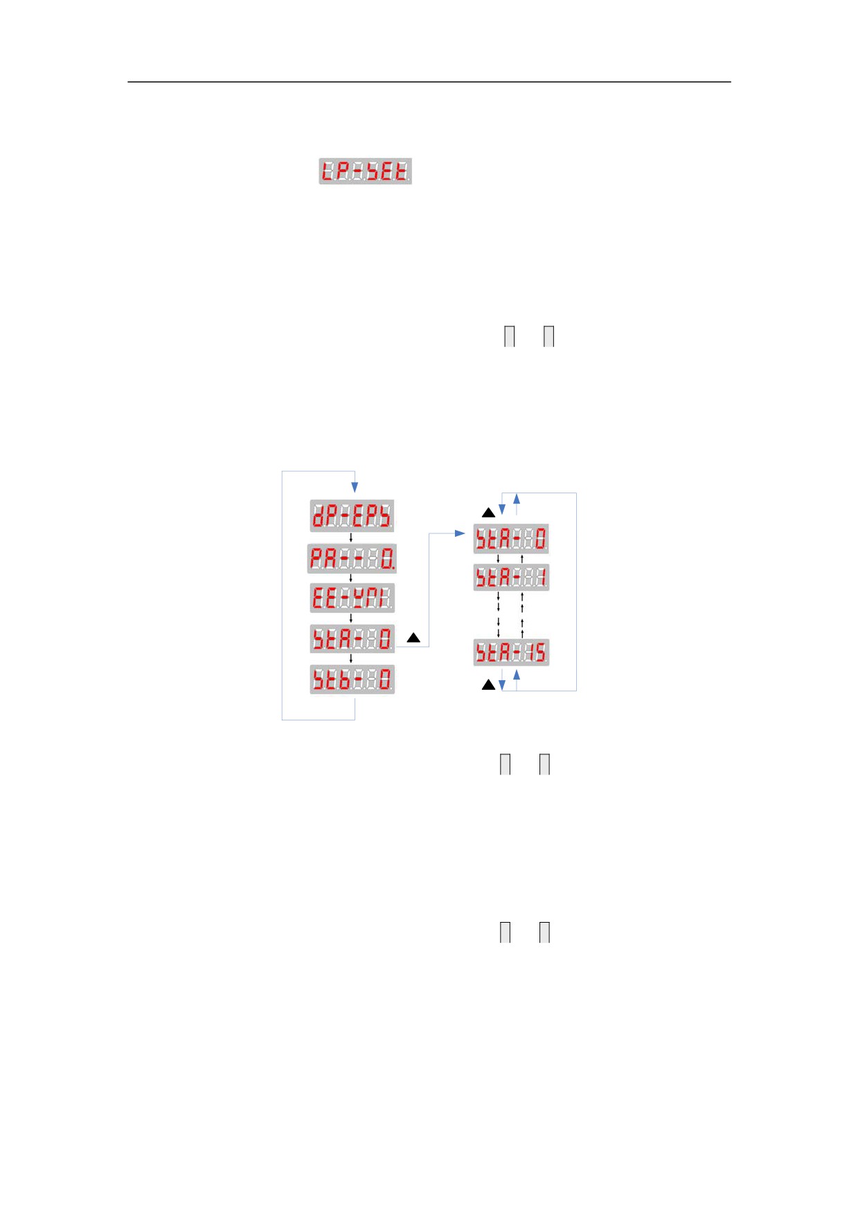
1 Automatically adjust parameters of the Servo Amplifier to match the
inertia of load .
HǃThe encoder reset
1 Support automatic reset of several encoders.
6.6 Operations in the Control Parameter Mode
1. On the main menu, select “STA-0”, and press
Ĺ
and
Ļ
to enter the secondary
menu for the control parameter mode.
2. Series HSV-180AD Servo Amplifier contains 16 types of control parameters.
Figure 6-9 Secondary menu for the control parameter mode
1. On the main menu, select “STA-0”, and press
Ĺ
and
Ļ
to enter the secondary
menu for the control parameter mode.
2. Series HSV-180AD Servo Amplifier contains 16 types of control parameters.
6.7Operation in the Auxiliary Mode
1. On the main menu, select “STA-0”, and press
Ĺ
and
Ļ
to enter the secondary
menu for the control parameter mode.
2. Series HSV-180 AD Servo Amplifier contains 16 types of control parameters.
Figure 6-10 Secondary menu for the auxiliary mode
114
6.8 Control Parameter Setting and Saving
Caution
z
The control parameter setting cannot take effect immediately. The new
parameter can be confirmed by pressing
S only in the "EE-WRI" of auxiliary
mode, and it takes effect after restarting the Servo Amplifier.
z
Wrong settings may cause improper operation that leads to accidents.
1. Select
on the main menu, press
Ĺ
and
Ļ
to select a control
parameter number, and then press
S
to display the value of the parameter. Press
Ĺ
and
Ļ
to change the parameter value.
2. The parameter value increase or decrease 1 every time you press
Ĺ
or
Ļ
respectively.
3.After the parameter modification is completed,. the corresponding decimal
point on the LED digital tube light, press
S to return to the control parameter
mode menu.
3. The control parameter setting cannot take effect immediately. If changing or
setting parameters, you should firstly set
as
, then save the
parameter change by pressing
S
to return to the main menu and pressing
M to
select the auxiliary mode. Then press
Ĺ
and
Ļ
to select "EE-WRI”, and then
115

press
S
to save the changed parameter value to EEPROM. The wire control box
displays FINISH, indicating that the parameter value is saved.
4. The changed control parameter takes effect as a default control parameter after
restarting the Servo Amplifier.
NOTE:
If changing PA—24to PA--28ˈPA--59, you should firstly set
as
116
7. Parameter Setting
Attention
z Personnel that set parameters must understand the meanings of the
parameters. Wrong setting could result in damage to the equipment
and injuries.
z It is recommended that parameter modification be performed under
the condition that servo motor run without load.
7.1 Function Menu
7.1.1 Parameters illustration
Users can set various parameters for series HSV-180AD Servo Amplifier to
adjust or set the performances and functions of the Servo Amplifier. This section
describes the purpose and functions of these parameters. Understanding these
parameters is essential for a best use and operation of the Servo Amplifier.
Series HSV-180 AD Servo Amplifier parameters can be divided into four
categories: movement parameter , expanding movement parameter control
parameter and expanding control parameter. (applicable to movement parameter
mode , expanding movement parameter mode,control parameter mode
respectively and expanding control parameter mode). These parameters can be
viewed, set and modified by keys or computer serial ports on the wire control
box.
Table 7-1 Description of the three types of modes
Param
Mode
Group
eter
Description
No.
Movement
Able to set speed regulator, specially
parameter mode
0~43
modification, and motor related parameters.
Expanding
Able to set parameters I/O, I/O interface
movement
0~43
function, notch filter ,the nominal motor
parameter mode
current, speed etc
117
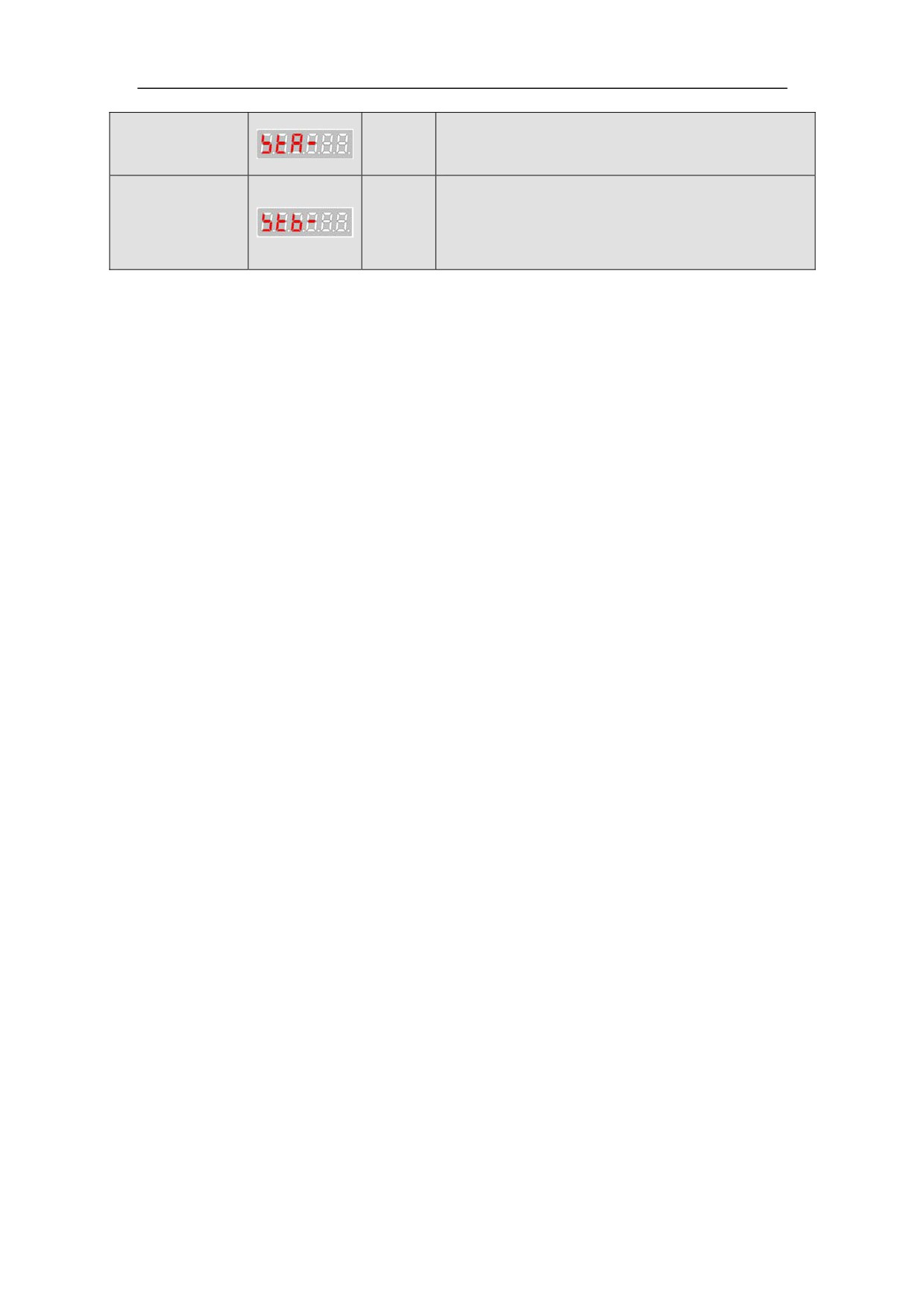
Control
Able to set servo orientation speed, orientation
0~15
parameter mode
positionDŽ
Expanding
Able to set control functions can be enabled
control
0~15
or disabled etc.
parameter mode
7.1.2 Parameter operation instructions
This section describes the modify and view parameters during debugging and
precautions, does not include the adjustment and adaptation of parameters
1ǃThe Servo Amplifier can only view the movement parameter PA, status
monitoring, auxiliary parameters and control parameters STA parameters after power
on.
2ǃSet PA—34to 2003, you could view or modify parameters PA and STB.
3ǃAny timeˈPA--23 ǃPA--24ǃ PA—25ǃPA—26 are effective only when
saving parameters and restarting power.
4ǃBefore the Servo Amplifier runningˈyou must modify parameter PA—43
˄Notice˖modify parameter PA--43 after setting PA--34 to 2003˅.
If the Servo Amplifier and motor code is not in Table 7.3ˈyou need to set the
parameters related to the motor manuallyˈand refer to 7.2.7.Non-standard motor
parameters
5ǃThe Servo Amplifier performance debugging please refer to the relevant sections
of 7.2.
6ǃThe steps of trial operation of the Servo Amplifier, please reference the relevant
sections of Chapter 8.
118
7.2 Movement Parameter Mode
7.2.1 Movement parameters
Series HSV-180AD Servo Amplifier can provide 44 movement parameters. For
details about the movement parameters, see Table 7-2, and Table 7-3.
In the application control mode:
P: indicates position control
S: indicates speed control.
T: torque mode
Table 7-2 Movement parameters
No.
Parameter
Applic
Value
Default
Unit
ation
Range
Value
Contro
l Mode
0
Position proportional
P
0.01 Hz
20̚10000
1000
gain
1
Position feed forward
P
1%
0̚150
0
gain
2
Speed proportional gain
P, S
20̚10000
400
3
Speed integral time
P, S
ms
15̚500
20
constant
4
Speed feedback filter
P, S
0̚9
1
factor
5
Current amplitude limit
P, S, T
30̚500
250
for maximum torque
6
Acceleration time
S
1ms/1000rpm
1̚32000
200
constant
7
Speed command input
S
100~9000
2000
gain
8
Speed command zero
S
-6000~6000
0
drift compensation
9
Torque command input
T
100~300
100
gain
10
Torque command zero
T
-1023~1023
0
drift compensation
Inversion of Table
P
position feedback
0 or 512
0
signal
11
Orientation-finished
P
0.0001 r
0̚3000
100
range
119
12
Position tolerance test
P
0.1r
1̚100
20
range
13
Position command
P
pulse frequency
1̚32767
1
molecular
14
Position command
P
pulse frequency
1̚32767
1
denominator
15
Maximum current
P, S, T
amplitude limit for
0̚500
280
1%
positive torque
16
Maximum current
P, S, T
amplitude limit for
-500̚0
-280
1%
negative torque
17
Maximum speed
P, S
10̚12000
2500
1r/min
limitation
18
Overload Torque
P, S, T
30̚200
200
1%
setting
19
Software overload time
P, S
40̚32000
1000
0.01s
20
Internal speed
S
-3200~3200
0
0.1r/min
21
JOG operation speed
P, S
0̚2000
300
1r/min
22
command pulse input
P
0~3
1
mode
23
Selection of control
P, S, T
0˖Position
mode
control
1˖Simulation
speed
0̚7
0
2˖Analog torque
3˖Internal rate
7˖Encoder Zero
calibration
24
Magnetic pole
P, S, T
logarithm of the servo
1̚20
3
motor
25
Encoder resolution
P, S, T
0˖1024
1˖2000
2˖2500
3˖6000
0̚9
2
4: ENDAT2.1
5˖BISS
6˖HiperFACE
7:TAMAGAWA
26
The encoder zero offset
PˈSˈ
-32467~
0
T
32767
27
Current control
PˈSˈ
10̚32767
2000
proportional gain
T
120
28
Current control
PˈSˈ
1̚2047
100
0.1ms
integration time
T
29
The second position
command pulse
P
1̚32767
1
frequency molecular
30
The third
position command
P
1̚32767
1
pulse frequency
molecular
31
-32467~
STA15-STA0
State control 1
4096
32767
32
Feed forward control
PˈS
0̚3000
0
1ms
filter time constant
33
Torque command filter
PˈS
0̚3000
0
1ms
time constant
34
User passport set
PˈSˈT
0̚2806
240
35
Position command
P
0̚3000
0
1ms
filter time constant
0˖2400bps
Communication baud
1˖4800bps
36
rate
0̚3
2
2˖9600bps
3˖19200bps
Position of serial
PˈS
37
1̚15
1
communication axis
36
Ratio of load inertia
P, S
0 ̚ 15
1
and rotary inertia
37
Mechanical load
P, S
0̚9
4
rigidity
38
Deceleration time
S
1̚32000
200
1ms/1000rpm
constant
39
The fourth
position command
P
1̚32767
1
pulse frequency
molecular
39
Position of serial
P, S, T
1 ̚ 63
1
communication axis
Unit˖ms˗
Brake output delay
PˈS
40
Brake Output Delay
0̚2000
0
time after the
servo OFF
Unit˖ 1rpm˗
Permissible speed
Only below this
PˈS
41
10̚300
100
brake output threshold
setting allows the
brake action
PˈS
42
Speed reach range
1̚500
10
Unit˖1rpm
121
thousand˖
0˖HSV-180AD
hundred˖
0˖35A
1˖50A
2˖75A
Specifications and
3˖100A
PˈS
43
Servo Amplifier type
0̚1999
101
4˖150A
code ƹ
5˖200A
6˖300A
7˖450A
Ten and a bit
indicates the type
of motorDŽSee
form7.3
Note:
If changing ƹ parameter, you should firstly set PA--34 to
, otherwise it’s
invalid.
Table 7-2 Movement parameters with Dench motor
Rated
Rated
Rated
Adapter
Power
Electric
Motor
PA-43
Adjusted
Torque
Servo
current
Type
parameters
Servo Amplifier
(Nm)
Amplifier
(A)
(KW)
GK6073-6AC61
2000
11
5.6
00
0
HSV-180AD-035
GK6080-6AC61
2000
16
6.8
01
1
GK6081-6AC61
2000
21
10
02
102
HSV-180AD-050
GK6083-6AC61
2000
27
13.3
03
103
GK6085-6AC61
2000
33
16.5
04
204
HSV-180AD-075
GK6087-6AC61
2000
37
18.5
05
205
GK6089-6AC61
2000
42
21
06
306
GK6105-8AC61
2000
45
19.5
07
307
HSV-180AD-100
GK6107-8AB61
1500
55
17.9
08
308
GK6109-8AB61
1500
70
23.1
09
309
122
Table 7-3 Movement parameters with Huada motor
Rated
Rated
Rated
Adapter
Power
Electric
Motor
PA-43
Adjusted
Torque
Servo
current
Type
parameters
Servo Amplifier
(Nm)
Amplifier
(KW)
(A)
110ST-M02515HMBB
1500
2.5
2.5
20
20
110ST-M03215HMBB
1500
3.2
2.5
21
21
110ST-M05415HMBB
1500
5.4
3.5
22
22
110ST-M06415HMBB
1500
6.4
4.0
23
23
110ST-M02420HMBB
2000
2.4
2.5
24
24
110ST-M04820HMBB
2000
4.8
3.5
25
25
130ST-M03215HMBB
1500
3.2
2.5
26
26
HSV-180AD-035
130ST-M05415HMBB
1500
5.4
3.8
27
27
130ST-M06415HMBB
1500
6.4
4.0
28
28
130ST-M09615HMBB
1500
9.6
6.0
29
29
130ST-M14615HMBB
1500
14.3
9.5
30
30
130ST-M04820HMBB
2000
4.8
3.5
31
31
130ST-M07220HMBB
2000
7.2
5.0
32
32
130ST-M09620HMBB
2000
9.6
7.5
33
133
130ST-M14320HMBB
2000
14.3
9.5
34
134
HSV-180AD-050
150ST-M14615HMBB
1500
14.6
9.0
35
135
150ST-M19115HMBB
1500
19.1
12.0
36
136
150ST-M22315HMBB
1500
22.3
13.0
37
237
150ST-M28715HMBB
1500
28.7
17.0
38
238
150ST-M14320HMBB
2000
14.3
9.0
39
239
HSV-180AD-075
150ST-M23920HMBB
2000
23.9
14.0
40
240
150ST-M26320HMBB
2000
26.3
15.5
41
241
123

7.2.2Extension movement parameters
Select PA—34 to2003 in the PA motion parameters , could see the extension
movement parameter model (PB parameter model), HSV-180AD have 44 extended
motion control parameters.
Table 7-4 Extension movement parameters
Applicable
Default
NO.
Parameter
Scope
Unit
Method
value
The second position
0
P
20̚10000
400*
0.1Hz
proportional gain
Second speed
1
PˈS
20̚10000
250*
proportional gain
The second
2
integration time
PˈS
15̚500
20*
ms
constant speed
The second torque
3
command filter time
PˈS
0̚500
0
0.1ms
constant
0˖ Fixed for the
first gain
1˖Fixed to the
second gain
2˖Switch control
Gain switching
cutover
P
4
0̚5
0
condition
3˖Command
frequency control
4˖Bias pulse
control
5˖Motor speed
control
Command frequency
0.1Kpps/unit
Gain switching
P
5
0̚10000
10
Deviation
threshold
pulse :pulse
Motor speed :1rpm
124