Series HSV-180AD AC Servo Amplifier. User's Manual (V1.00 2012.4) - page 3
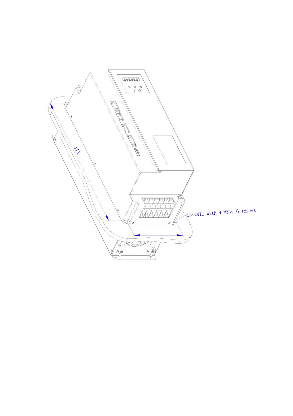
Figure 4-8 Wall installation diagram for external heat sink of HSV-180AD- 100, 150
Servo Amplifier
50
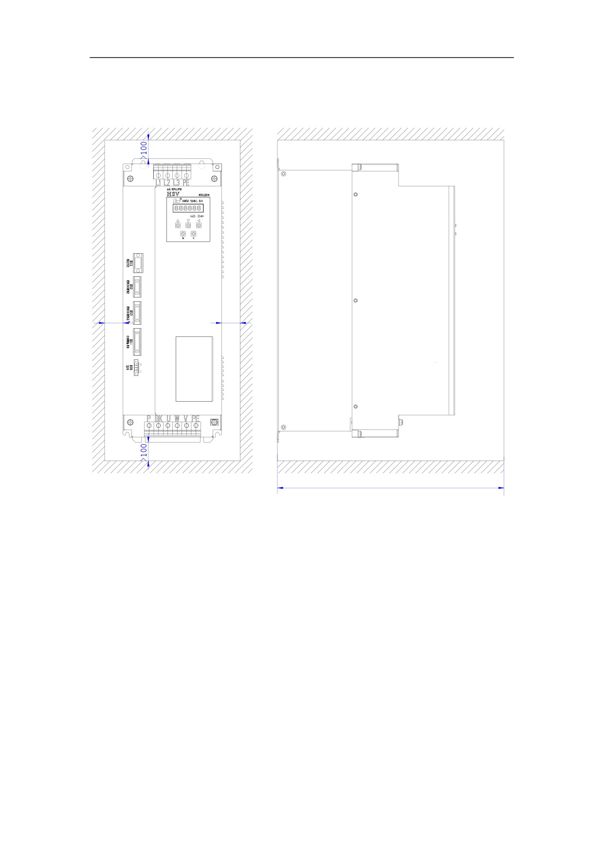
Figure 4-9 Wall installation diagram of HSV-180AD- 100, 150 Servo Amplifier (with
auxiliary devices)
!
!
! PP
51
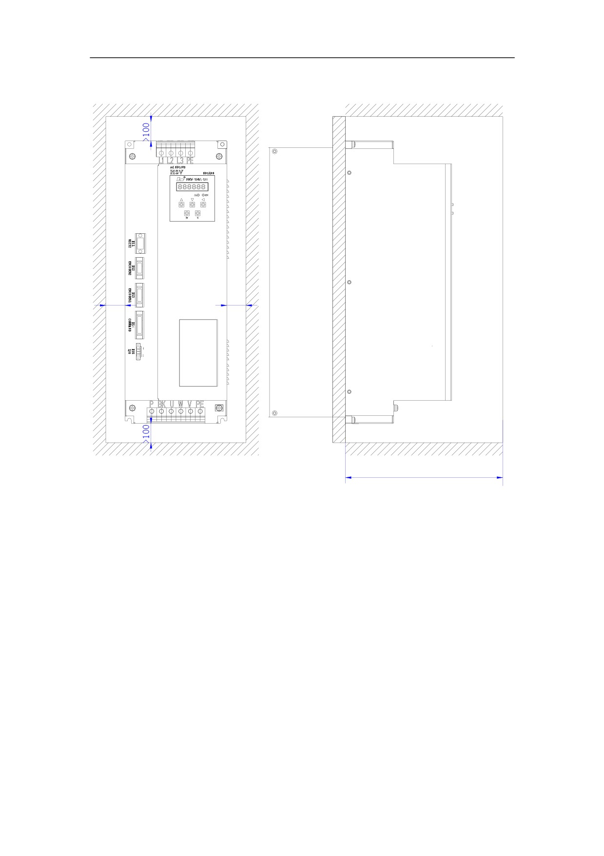
Figure 4-10 Installation interval of HSV-180AD- 100,150 single Servo Amplifier
!
!
! PP
52
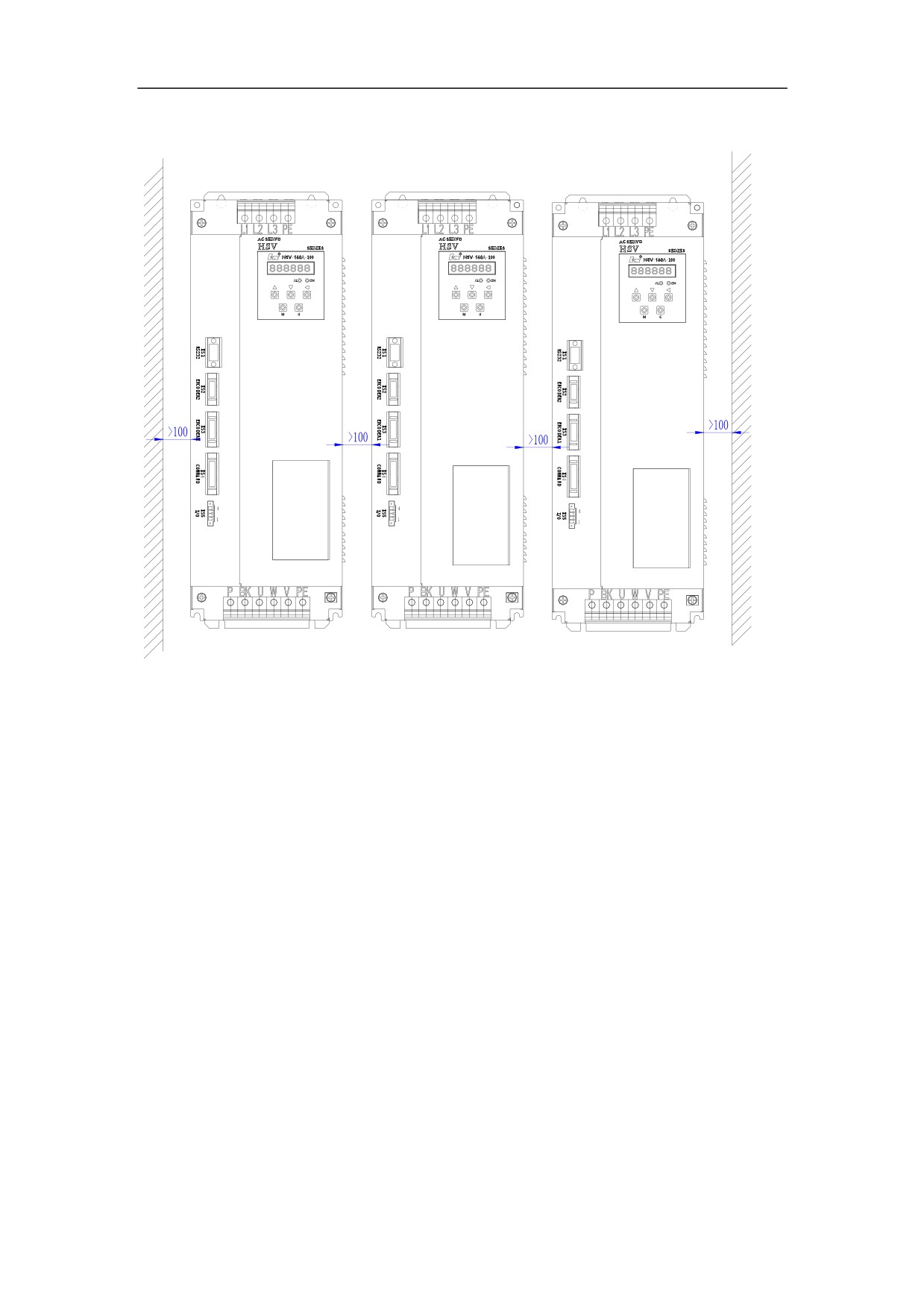
Figure 4-11 Installation interval of HSV-180AD- 100,150 multiple Servo Amplifiers
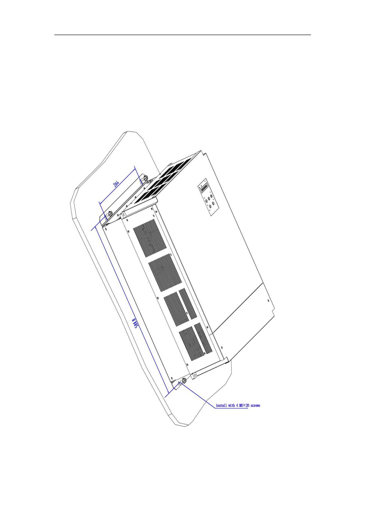
4.3.3Instllation method of HSV-180AD-200,300,450
1. Installation Methods
There are two types of wall installation: directly installed with auxiliary devices,
and external heat sink installation. For their installation diagrams, see Figure
4-12, Figure 4-13.You can use any of the three methods, and install the Servo
Amplifier verticallyDŽ
2. Installation Interval
For the installation interval of single Servo Amplifier, see Figure 4-14 and
Figure 4-15
For the installation interval of multiple Servo Amplifiers, see Figure 4-16
During installation, leave enough intervals as possible to ensure a good heat
emission.
53
3. Cooling
In the electric cabinet, there must be air blew through the radiator to prevent the
ambient temperature of the Servo Amplifier from overheating.
Figure 4-12 Wall installation diagram of HSV-180AD-200,300,450 Servo
Amplifier (with auxiliary devices)
54
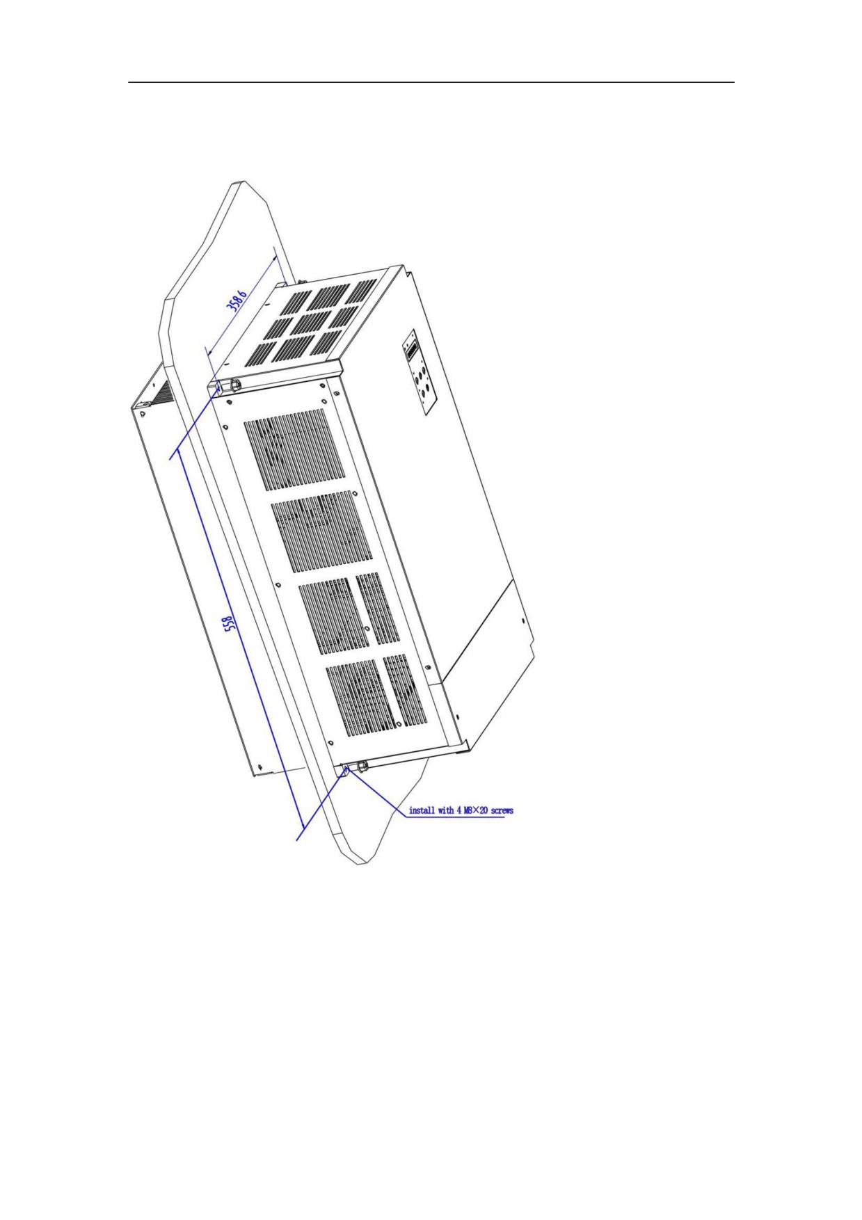
Figure 4-13 Wall installation diagram for external heat sink of HSV-180AD- 200,
300,450 Servo Amplifier(without auxiliary devices)
55
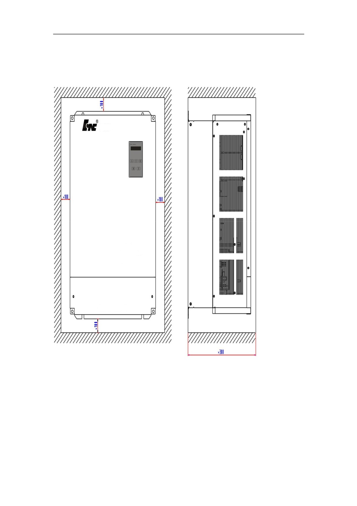
Figure 4-14 Installation interval of HSV-180AD- 200,300ˈ450 single Servo
Amplifier ˄wall station˅
56
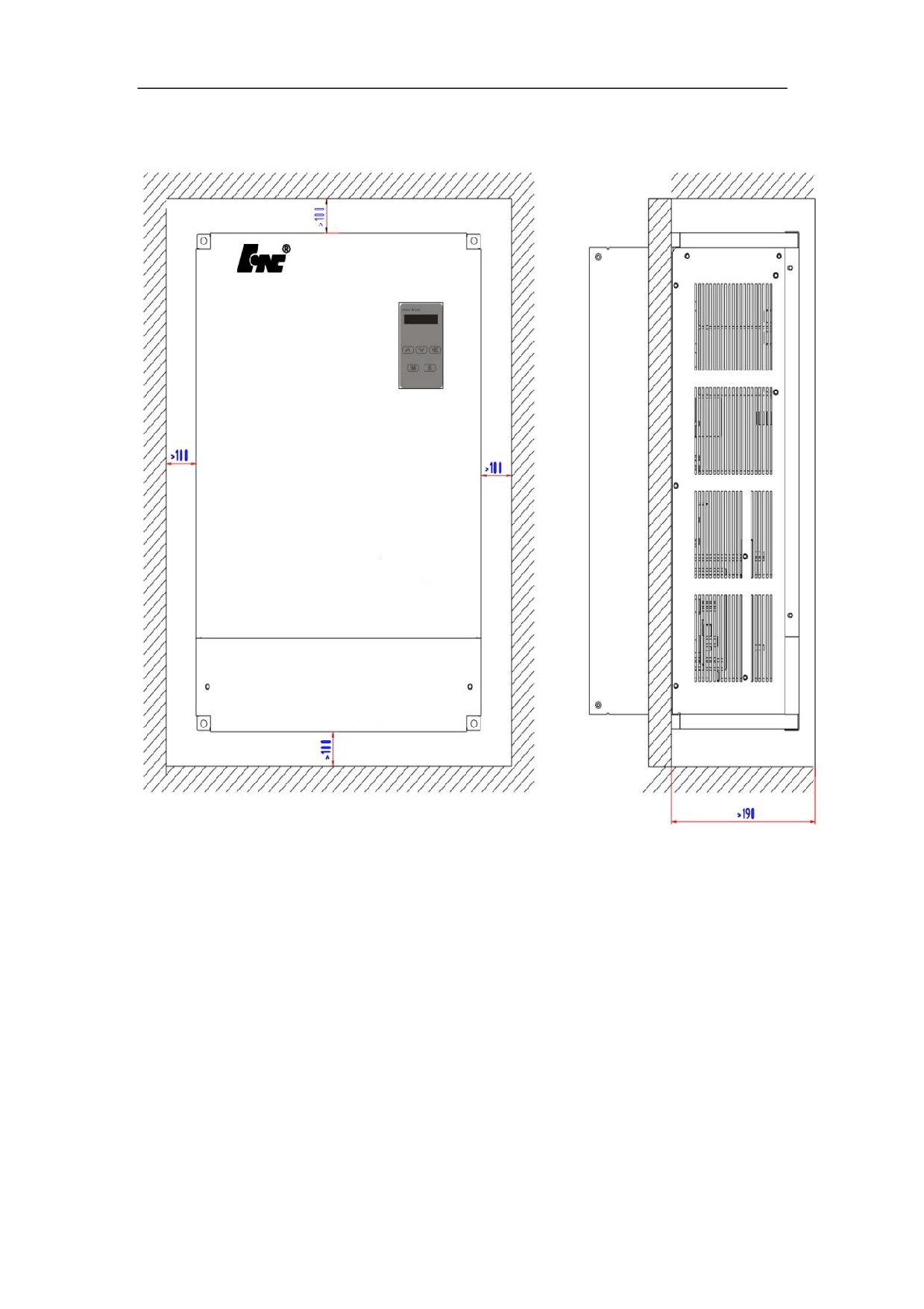
Figure 4-15 Installation interval of HSV-180AD- 200,300,450 single Servo Amplifier
57
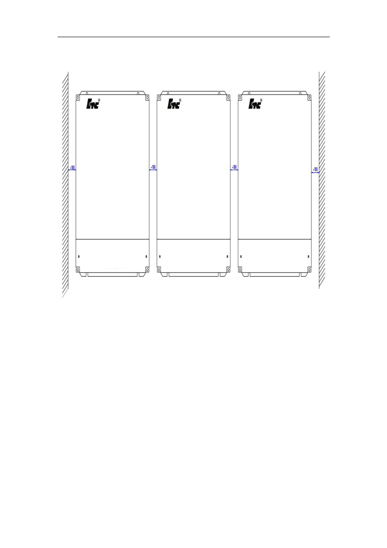
Figure 4-16 Installation interval of HSV-180AD- 200,300,450 multiple Servo
Amplifiers
58
4.4 Installation of Servo Motor
Warning
z Do not knock the motor or encoder so as to prevent the motor
from oscillation or impact.
z When carrying the motor, do not drag the motor shaft,
leading-out wire or encoder.
z Do not overload motor shaft, otherwise the motor may be
damaged.
z The motor must be firmly installed and prevent loosening.
4.4.1 Installation Environment
1. Prevention
The servo motor is not water-proof. When installing and operating, the motor
must be guard against liquid spilling and prevent oil mist from entering the
motor through motor leads and motor shaft. If users need water-proof motor,
make it clear when ordering.
2. Temperature and Humidity
The environmental temperature must be between 0 degree Celsius and 40 degree
Celsius. Humidity cannot greater than 90% RH and there is no condensation.
After long-time operation, the motor will heat up. It is recommended that you use
forced cooling or use derating motors if there is less space or the motor is closed
to heating equipments
3. Oscillation
The motor must be free from oscillation, and take measures to control the
oscillation below 0.5 G˄4.9m/S2˅.
59
4.4.2 Installation Method
1. Installation Method
The GK6 series can be installed vertically and horizontally.
2. Installation Notes
During installing and removing pulley, do not knock the motor or motor
shaft to prevent damaging the encoder. Use the spiral drawing tools to
install and remove the thermal expansion expansion-type coupling.
Series GK6 servo motors cannot withstand large axial load or radial load.
It is recommended that you use flexible couplings to connect it with the
load.
When fixing the motor, use spring washer to tighten the bolts to prevent
loosening
60
5 Wiring
Warning
z Wiring and wiring inspection personnel must have required
capabilities.
ƽ Wiring and wiring inspection personnel must wait 5 minutes after
power off for all wiring or wiring check to prevent from
electronic shock.
Caution
ƽ Must be wiring in accordance with the terminal voltage and the
polarity to prevent from equipment damage or personal injury.
ƽ The Servo Amplifier and servo motor must be reliably grounded.
z Do not directly hammer at the motor shaft when connect or
disconnect its mechanic part to protect encoder from being
damaged.
ƽ Try to align the motor shaft to the optimum level to prevent from
oscillation or bearing damage.
5.1 connectors
61
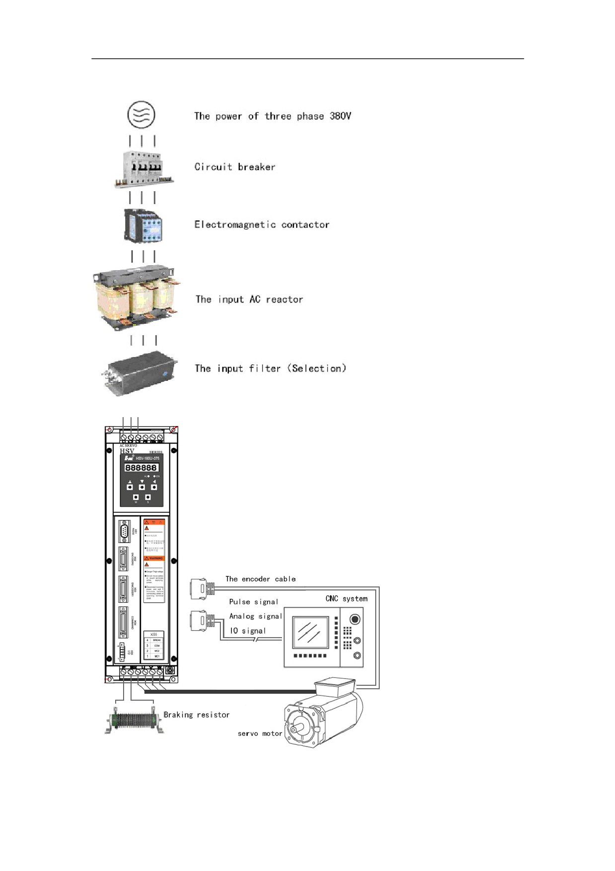
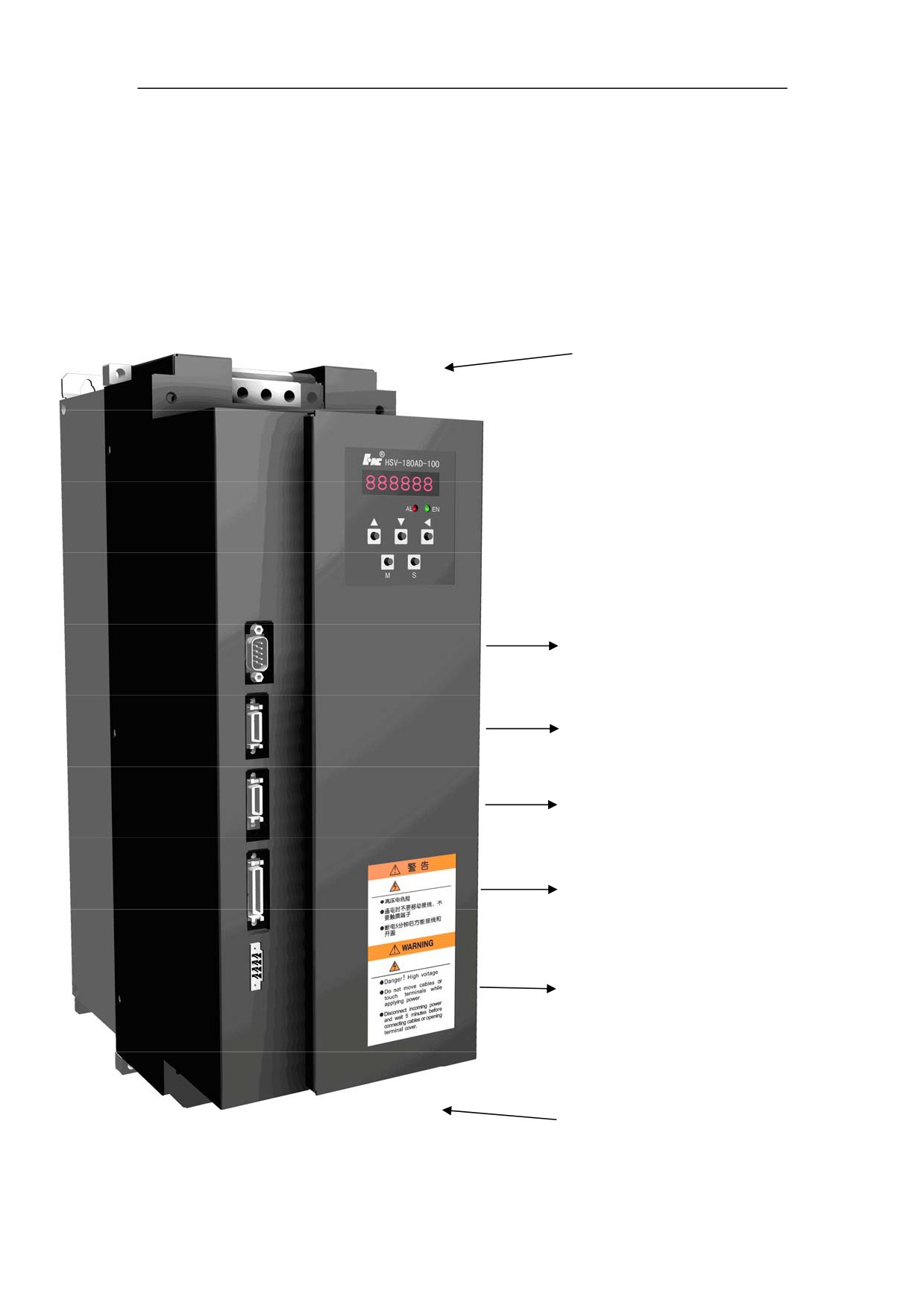
Figure 5-1 shows the interface configuration of HSV-180AD
62
5.2 Terminal Configuration
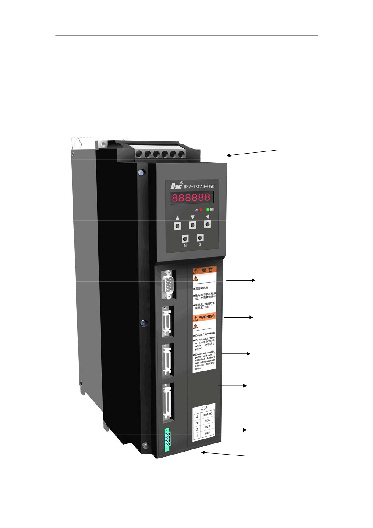
Figure 5-2 shows the interface configuration of HSV-180AD. In the figure, XT1
and XT2 are the terminal blocks; XS1 is a DB9 socket; XS2, XS3, and XS4 are
high-density sockets; XS5 is a wiring terminal.
Figure 5-2 Interface configuration of HSV-180AD
XT1 power input
terminal
XS1 RS232
Communication interface
XS2 ENCODER Second position
encoder input interface
XS3 ENCODER1Servo motor
encoder input interface
XS4 COMMAND
Command input / output
interface
XS5 input / output terminal
XT2 Power output terminal
63
XT1 power input
terminal
XS1 RS232
Communication interface
XS2 ENCODER Second position
encoder input interface
XS3 ENCODER1Servo motor
encoder input interface
XS4 COMMAND
Command input / output
interface
XS5 input / output terminal
XT2 Power output terminal
64
5.3 Terminal Configuration
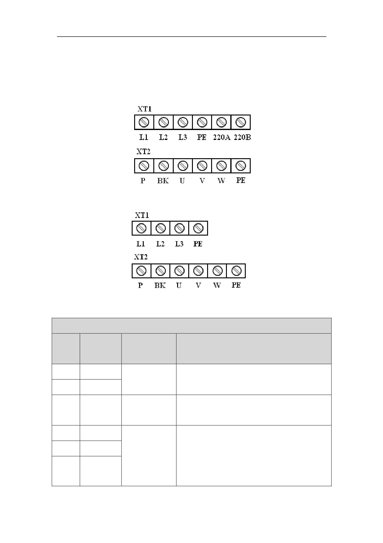
5.3.1 Terminals of HSV-180AD-035ˈ050ˈ075ˈ100ˈ150
Figure 5-3 Soldering terminal of HSV-180AD-035,050,075
Figure 5-4 Soldering terminal of HSV-180AD-100,150
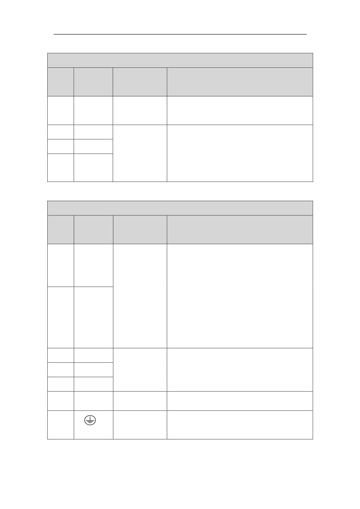
Gram5.1 XT1 power input terminal of HSV-180AD-035ˈ050ˈ075
XT1 power input terminal of HSV-180AD-035ˈ050ˈ075
Terminal
NO.
Signal
Function
Symbol
1
220B
Reserved
2
220A
Ground
Ground terminal, and the ground resistance is
3
PE
terminal
less than 4ȍ
4
L3
Three-phrase
Main circuit power supply input terminal
5
L2
main circuit
Three phrase AC380V/ 50Hz
power input
Note:
6
L1
terminal
Do not connect to the output terminal U, V, W.
65
Gram5.2 XT1 power input terminal of HSV-180AD-100ˈ150
XT1 power input terminal of HSV-180AD-100ˈ150
Terminal
NO.
Signal
Function
Symbol
Ground
Ground terminal, and the ground resistance is
1
PE
terminal
less than 4ȍ
2
L3
Three-phrase
Main circuit power supply input terminal
3
L2
main circuit
Three phrase AC380V/ 50Hz
power input
Note:
4
L1
terminal
Do not connect to the output terminal U, V, W.
Gram 5.3 Heavy Current Output Terminal of HSV-180AD-035,050,075,100,150
HSV-180AD-035ˈ050ˈ075,100,150 XT2 heavy current output terminal
Terminal
NO.
Signal
Function
Symbol
z Build-in 70ȍ/500W braking resistors.
z If only use the braking resistor, the
1
P
terminal P and BK must be disconnected to
Connection
avoid short-circuit.
z
If an external braking resistor is used,
terminal for
terminal P and BK must be connected to an
external
external braking resistor.
Note:
2
BK
braking resistor
Terminal P and BK cannot be shorted.
Otherwise, the Servo Amplifier may be
damaged.
3
U
Three-phrase
output terminal
It must be linked to the motor U, V, and W
4
V
of the Servo
terminals correspondingly.
5
W
Amplifier
Ground
Ground terminal
6
PE
terminal
Ground resistance is less than 4ȍ
Ground terminal
Ground
Ground resistance is less than 4ȍ
terminal
Servo Amplifier housing ground terminal
66
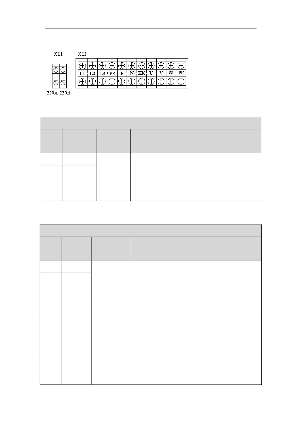
5.3.2 Terminal Configuration HSV-180AD-200,300,450
Figure 5-5 Soldering terminal of HSV-180AD-200,300,450
Gram5.4 XT1 power input terminal of HSV-180AD-200,300,450
XT1 power input terminal of HSV-180AD-035ˈ050ˈ075
Terminal
NO.
Signal
Function
Symbol
single-phra
1
220A
single-phrase input terminal of main circuit power
se input
AC220V/50Hz
terminal of
Main circuit power supply input terminal
control
2
220B
Three phrase AC380V/ 50Hz
power
Gram 5.5 XT2 Heavy Current Output Terminal of HSV-180AD-200,300,450
HSV-180AD-200,300,450 XT2 heavy current input/output terminal
Termina
NO.
Signal
Function
l Symbol
1
L3
Three-phrase
Main circuit power supply input terminal
main circuit
Three phrase AC380V/ 50Hz
2
L2
power input
Note:
3
L1
terminal
Do not connect to the output terminal U, V, W.
Ground
Ground terminal
4
PE
terminal
Ground resistance is less than 4ȍ
Terminal P and BK is used to DC current input or
Positive
an external braking resistor.
5
P
Of
Note:
generator
Terminal P and BK cannot be shorted. Otherwise,
the Servo Amplifier may be damaged.
Terminal P and BK is used to DC current input
Negative of
Note:
6
N
generator
Terminal P and BK cannot be shorted. Otherwise,
the Servo Amplifier may be damaged.
67
There is no build-in braking resistors, must use an
Connection
external braking resistor, terminal P and BK must
terminal for
be connected to an external braking resistor.
7
BK
external
Note:
braking
Terminal P and BK cannot be shorted. Otherwise,
resistor
the Servo Amplifier may be damaged.
Three-phrase
U
output
8
It must be linked to the motor U, V, and W
V
terminal of
terminals correspondingly.
the Servo
W
Amplifier
Ground
Ground terminal
9
PE
terminal
Ground resistance is less than 4ȍ
Ground terminal
10
Ground
Ground resistance is less than 4ȍ
terminal
Servo Amplifier housing ground terminal
5.3.3 Side wring of main circuit input
Figure 5-6 Soldering terminal of main circuit input
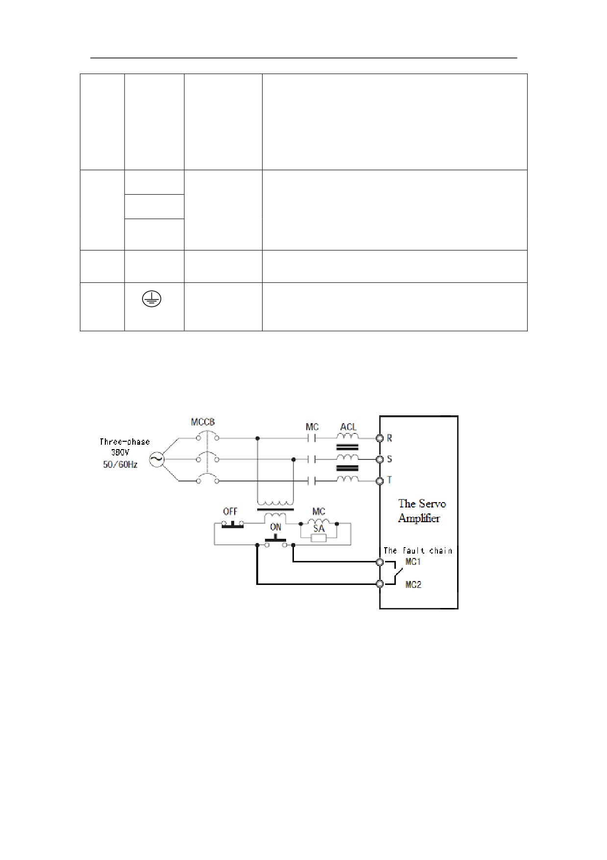
1ǃCircuit Breaker (MCCB)
Circuit breaker must be connected between the three-phrase AC power
supply and power input terminals L1, L2, L3 on XT1 so as to cut off the
power when the Servo Amplifier is over circuited or short circuited.
MCCB capacity is generally 1.5 to 2 times of the rated motor current, refer to
Table 3.1
68
MCCB's time characteristics should considerate the Servo Amplifier (motor
rated current 1.5 to 2 times, 1 min) and time characteristics.
Each Servo Amplifier must be corresponding to a MCCB˗when multiple
Servo Amplifiers share a MCCB, In order to cut off the power supply and
prevent the failure expandingˈsuggest using the failure chain output relay of
Servo Amplifier to control the line magnetic contactor to ensure safetyDŽ
2ǃleakage circuit breaker
When choosing a specific leakage circuit breakerˈplease select Operating
current of Servo Amplifier above 30mA.
When choosing a general leakage circuit breakerˈplease select Operating
current of Servo Amplifier above 200mA,time is above 0.1SDŽ
Installing isolation transformer between a general leakage circuit breaker and
Servo Amplifier could effectively avoid the breaker malfunction
3ǃLine electromagnetic contactor
Line electromagnetic contactor capacity is generally 1.5 to 2 times the rated
motor current selection, please refer to Table 3.1
Frequently using open / closed magnetic contactor will cause heating of the
soft-start resistance, and even burning.
Interval time of open / closed magnetic contactor should be more than 10
minutes
4ǃ Surge Suppressors
In order to eliminate arc and damage, extend the life of the contactor
connect a three-phase AC interrupter serve on output main contact of electromagnetic
contactor
5ǃInput AC reactor
In order to protect the rectifier components from damage caused by the high-current's
impacting to the input power circuit, the power input side need to connect to an input
AC reactor and increase its power factor. It can effectively eliminate the influence of
high harmonics, prevent other equipment from damage caused by the voltage wave
changes, and eliminate the unbalanced input current caused by phase voltage
unbalanced.
Input AC reactor capacity is generally 1.5 to 2 times of the rated motor current,
69
please refer to the Table 3.1.
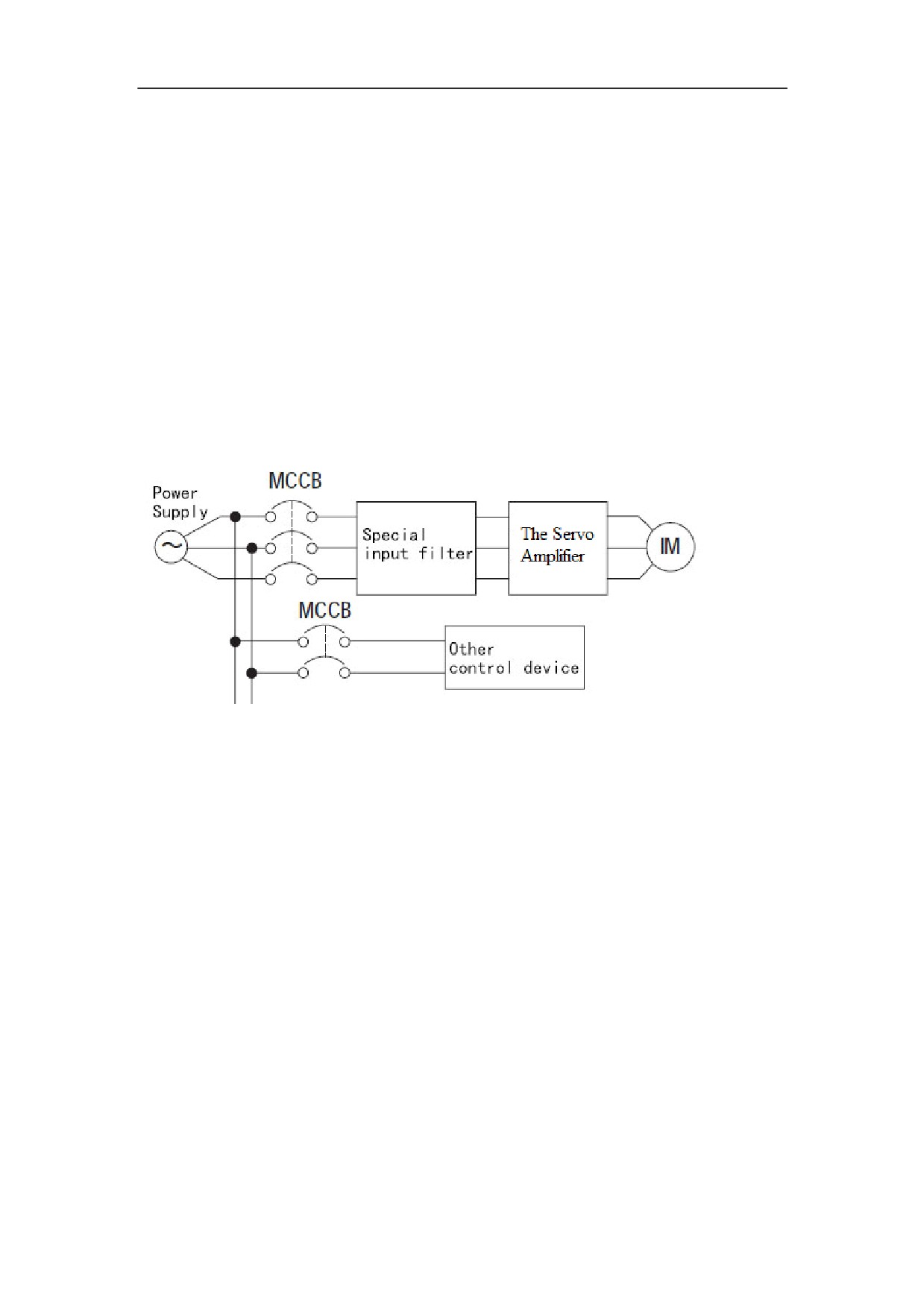
6ǃInput filter
In order to reduce a high-frequency interference noise from source line coupling to
Servo Amplifier, suggest install matching input filter on the current input of Servo
Amplifier.
Input filter capacity is generally 1.5 to 2 times the rated motor current selection,
please refer to Table 3.1.
Please select the dedicated servo (inverter) input filterDŽ
Input filter should be well grounded
)LJXUH
,QSXW ILOWHU RQ WKH FXUUHQW LQSXW RI Servo Amplifier
5.3.4 Control power wiring
HSV-180AD-200ˈ300ˈ450 Servo Amplifier must connect AC220Vcontrol
powerˈduring power-on process, you should connect AC220V control power firstly
and then connect the AC380V strong electric powerDŽ
5.3.5 Output side wiring of main circuit
1ǃMotor Connection
Output terminals UǃVǃW of Servo Amplifier should connected to terminals Uǃ
VǃW of the three-phase AC motor according to the correct phase
If A30 motor phase sequence error alarm appears at the first running,
prompt users motor terminal phase sequence error will be wrong, you just
need to exchange V,W
Distance between Servo Amplifier and motor wiring should generally be less
than 40 m
70
2ǃExternal Braking Resistor
The braking voltage of HSV-180AD Servo Amplifier is DC700 V. For the
maximum braking current, see Table 3.1.
(1)A 70 ȍ/500 W braking resistor has been built in HSV-180AD-035ˈ050ˈ
075and a maximum of five times overload is allowed (continuing for one second). An
external braking resistor is required when the Servo Amplifier 's load or inertia is big.
The braking time is shorter when the load or inertia is bigger, and the resistance value
is smaller and its power is bigger. However, the maximum braking current cannot
exceed the Servo Amplifier's maximum braking current. Generally, the total braking
power of the braking resistor is 10% to 20% of the rated motor power.
Connect P and BK terminals of the Servo Amplifier with the external braking
resistor if an external braking resistor is used. In this case, the internal resistor and the
external resistor are serial connected. Table 5.8 shows the recommended external
braking resistor.
(2) There is no braking resistor built in HSV-180AD-100ˈ150ˈ200ˈ250ˈ
300ˈ450,you have to connect to external braking resistor. The braking time is shorter
when the load or inertia is bigger, and the resistance value is smaller and its power is
bigger. However, the maximum braking current cannot exceed the Servo Amplifier's
maximum braking current. Generally, the total braking power of the braking resistor
is 10% to 20% of the rated motor power.
Connect P and BK terminals of the Servo Amplifier with the external braking
resistor if an external braking resistor is used. In this case, the internal resistor and the
external resistor are serial connected. Table 5.8 shows the recommended external
braking resistor.
71
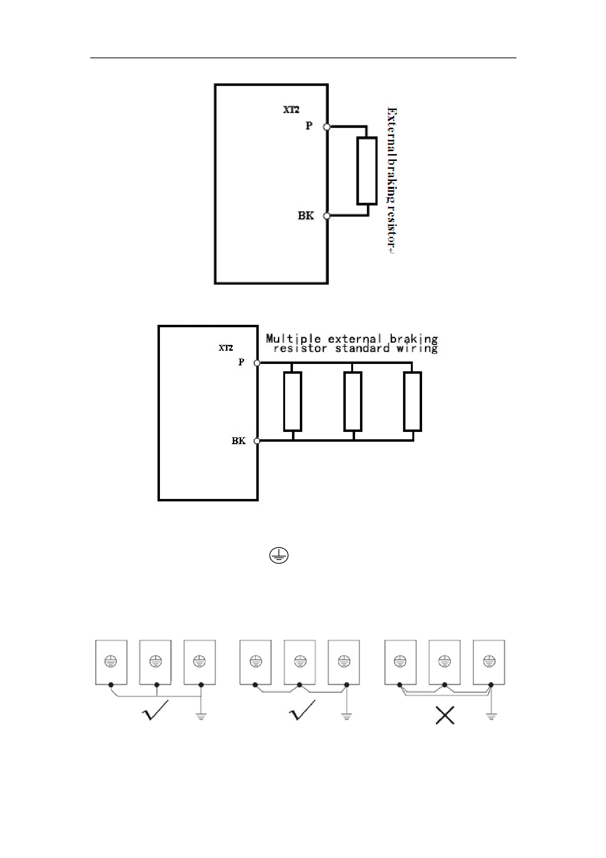
Figure 5-8 single external braking resistor standard wiring
Figure 5-9 multiple external braking resistor standard wiring
3ǃGround Connection
Ground terminal or PE or
ˈbe sure to groundDŽ
Ground resistance is less than 4ȍ
Ground wire of Servo Amplifier cann’t use with welder and other power
equipment at the same time.
Figure 5.10 Ground connection
72
5.4 connection of control signal terminals
5.4.1 XS4 COMMAND input/ output terminals
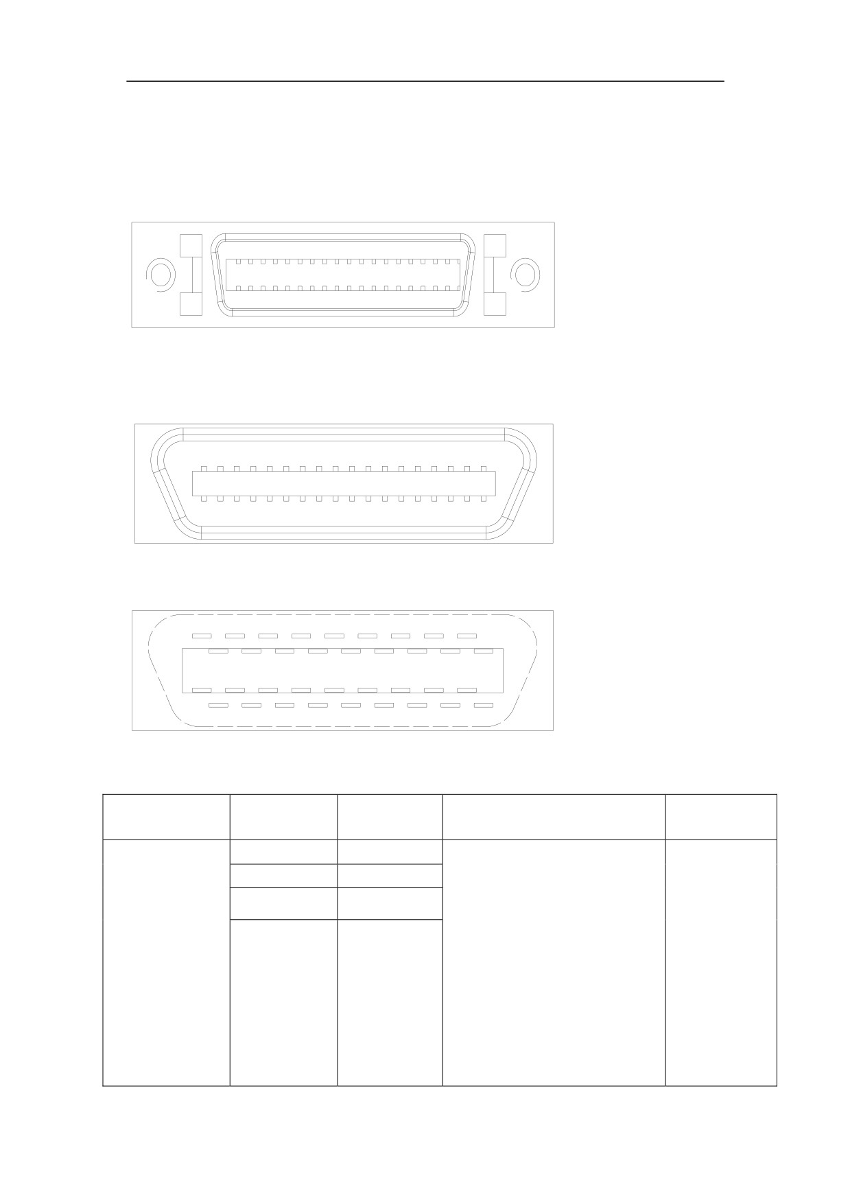
Figure 5-11 XS4 command input/output interface
Figure 5-12 Plug of XS4 command input/output interface plug (looking from the
plug)
Figure 5-13Soldering terminal of XS4 command input/output interface (looking from
the soldering terminal)
5.4.1.2 XS4 COMMAND Input/output Interface
Type
Terminal
Terminal
Function
Signal
Symbol
Command
14
CP+
Input terminal for external
Line
pulse input
15
CP-
command pulse
drive
Note:
receiving
16
DIR+
You can set the pulse input
RS422
17
mode by setting the
standard
movement parameter PA--22.
Command pulse + characters
DIR-
CCW/CW command pulse
mode
2-phase command pulse
mode
73
Servo motor
32
A+
line drive
Encoder A output
optic-electrical
33
A-
output
encoder
18
B+
RS422
Encoder B output
36
B-
standard
35
Z+
Encoder Z output
34
Z-
PNP output
21,22
Z_OUT
Z-phase pulse output
100mA
NPN
Z-phase pulse output
31
ZPLS_OUT
output
100mA
23,24
GNDDM
Digital signal ground
0V
Analog output
Analog output terminal
DC -10̚
terminal
12
AN+
+10Vor 0̚
+10V
Reference terminal for analog
13
AN-
input
27,28
GNDAM
Analog signal ground
0V
SW input signal
Servo enable input terminal
0Vcommon
EN ON˖Enable the Servo
point
Amplifier
0V input
1
EN
EN OFF˖The Servo
effective
Amplifier stops working, and
the motor is idle.
Alarm clear input terminal
ACL ON: Clear system
2
A_CL
alarm
ACL OFF: Keep system
alarm
Position error counter
clearance input terminal
3
CLEE
CLEE ON: In the position
control mode, clear the
position error counter.
Command pulse prohibition
Command pulse prohibition
4
INH
input terminal
CCW drive prohibition input
terminal
OFF: CCW drive is allowed.
5
L-CCW
ON˖CCW drive is not
prohibited.
cancelledDŽ
74