Series HSV-180AD AC Servo Amplifier. User's Manual (V1.00 2012.4) - page 2
3.2 Specification of Servo Motor
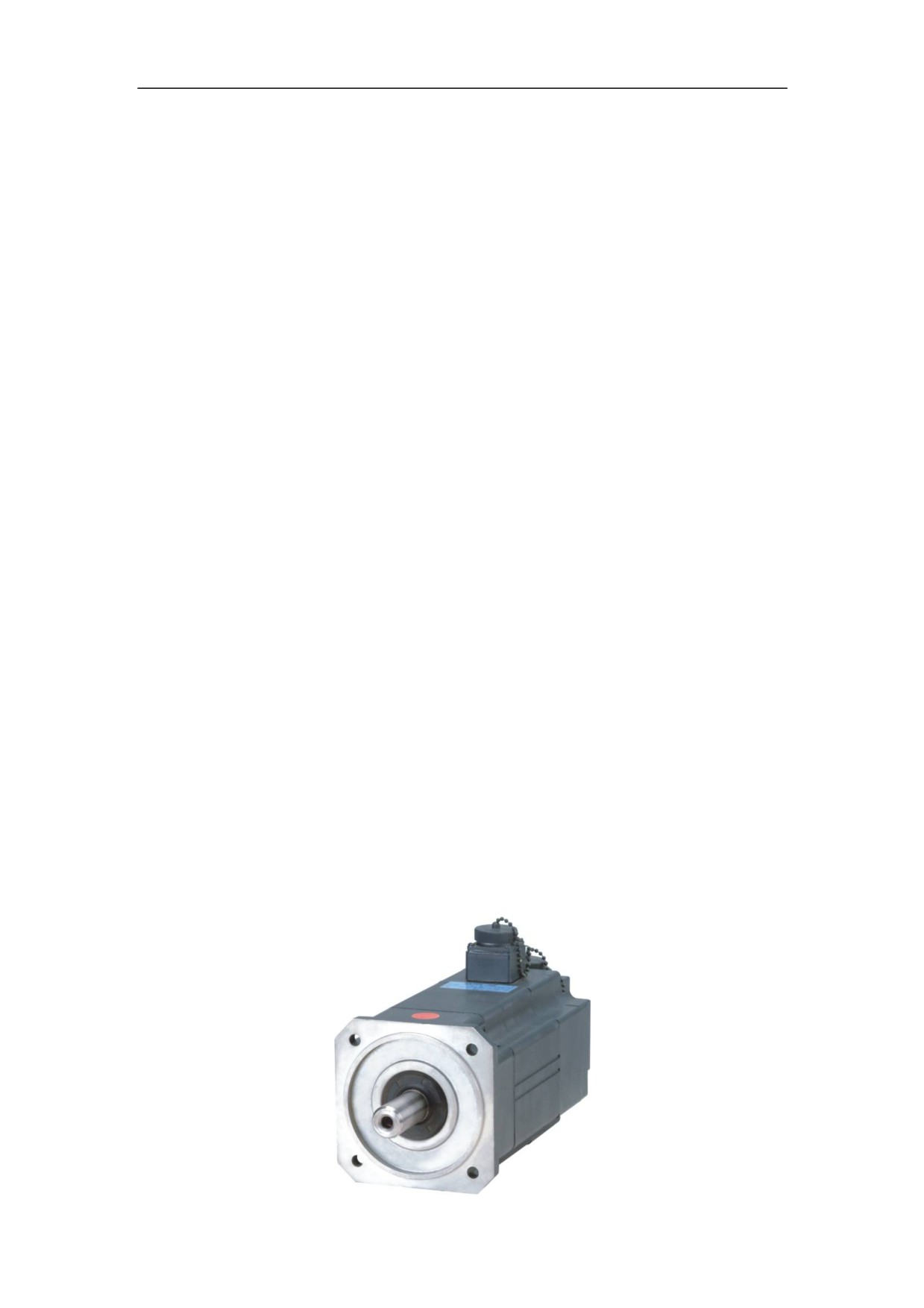
3.2.1 Introduction to Series GK6 AC Servo Motor
GK6 series of AC servo motors and the Servo Amplifier can be widely used in
various fields such as machine tools, textile, printing, and building materials.
GK6 AC servo motor uses self-cooling motor, and its protection class reaches
IP64-IP67. GK6 AC servo motor is a three-phase AC permanent magnet synchronous
motor that uses high-performance rare earth permanent magnetic materials to form air
gap magnetic field. Pulse width modulation (PWM) inverter is used to control
operation to achieve good torque performance and wide speed range. A temperature
sensor is installed in the stator windings of the servo motor, which is used for
overheat protection. GK6 series of AC servo motors consist of stator, rotor, and
high-precision feedback devices (such as optical encoder and resolver).
3.2.2 Features of Series GK6 AC Servo Motor
z Compact architecture and high power density
z Small rotor inertia and rapid response
z Super high coercively rare earth permanent magnet
z Overheat protection capability
z Strong anti-demagnetization capability
z Various frame installation size
z Full-closed design
Figure 3-4 Series GK6 AC servo motor
25

3.2.3 Technical index of Series GK6 AC servo motor
The following table describes the technical index of series AC GK6 servo motor.
Table 3.3 Technical index of series GM7AC servo motor:
Item
Description
Magnetic material
Ɣ Super high coercively rare earth permanent magnetic
Insulation level
material.
Ɣ Class F insulation level
When the environmental temperature is +40ć, the rotor
winding temperature can reach 100 K (ᇞT=100 K). Class
H or Class C insulation level is optional, in which case
the rotor
Feedback system
Winding temperature can reach 125 K or 145 K
respectively.
Ɣ Standard: square-wave optic-electrical encoder (with
U, V, and W signal)
Options:
z Resolver, used in the environment with big vibration
Temperature
and impacts
protection
z Sine and cosine optic-electrical encoder, which
resolution can reach
220
z Absolute encoder
Ɣ Positive temperature coefficient (PTC) thermistor
When the temperature is 20°, the resistance cannot
greater than 250 ȍ (R 250 ȍ).
Option: Heat-sensitive switch
Temperature
positive temperature coefficient(PTC) thermistor
protection
Types of mounting
ƔMB5
Protection level
Options: IMV1, IMV3, and IMB35 IMB5
Cooling
ƔIP64
Options: IP 65 and IP67
Surface paint
ƔNatural cooling
ƔFlat grey paint
Options: customized paint
Bearing
ƔDouble row deep groove ball bearing
Radial shaft seal
ƔDrive shaft seal
Shaft
ƔStandard:
Type a: Plain shaft, no keys
Option:
z Type b: Shaft with keyway, keys, or customized
shaft
26

Vibration level&
ƔN
Rotation accuracy
Options: R and S
ƔN
Option: R and S
Noise
GK60355dB(A);
GK60455dB(A);
GK60560dB(A);
GK60665dB(A);
GK60765dB(A);
GK60870dB(A);
GK61070dB(A);
GK61370dB(A);
GK61876dB(A);
Connection
ƔSocket connector (GK603-GK610)
Option: Outlet box (GK603-GK610)
ƔOutlet box (GK613 or a later version)
Option: Socket connector
Options
ƔMaintenance-free high-reliability permanent magnet
safe brake (made in Germany)
ƔHigh-precision planetary gear reducer or other reducers
27
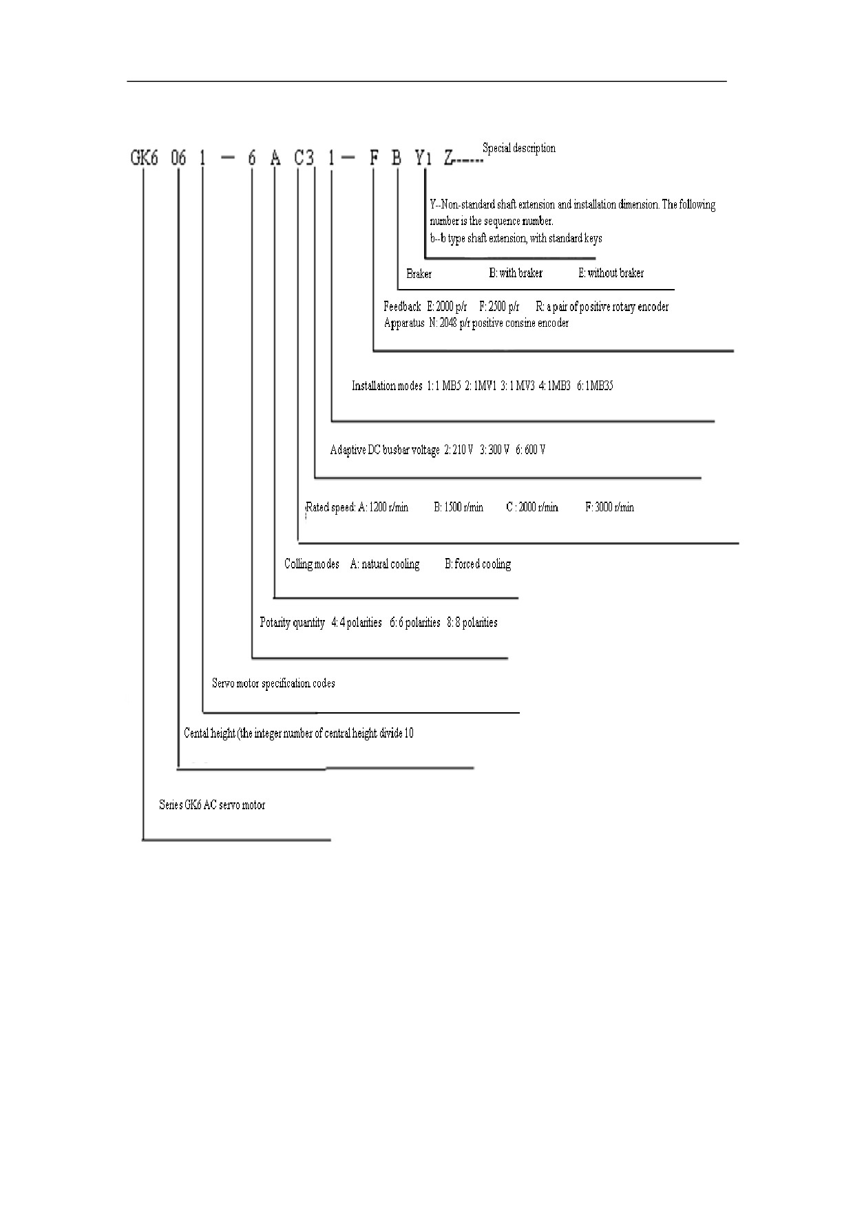
3.2.4Order information of series GK6 AC Permanent Magnet Servo
3.2.5 Technical Specification of Series GK6 AC Permanent Magnet
Servo Motor
Adhere to the following principles when choosing the Servo Amplifier:
z Generally, the maximum current or rated current of the Servo Amplifier must
be equal or greater than 2.
z For the situation that requires great dynamic response characteristics, the
maximum current or rated current must be equal or greater than 3.
The following tables describe the technical specification of series GK6 AC permanent
magnet servo motor
28
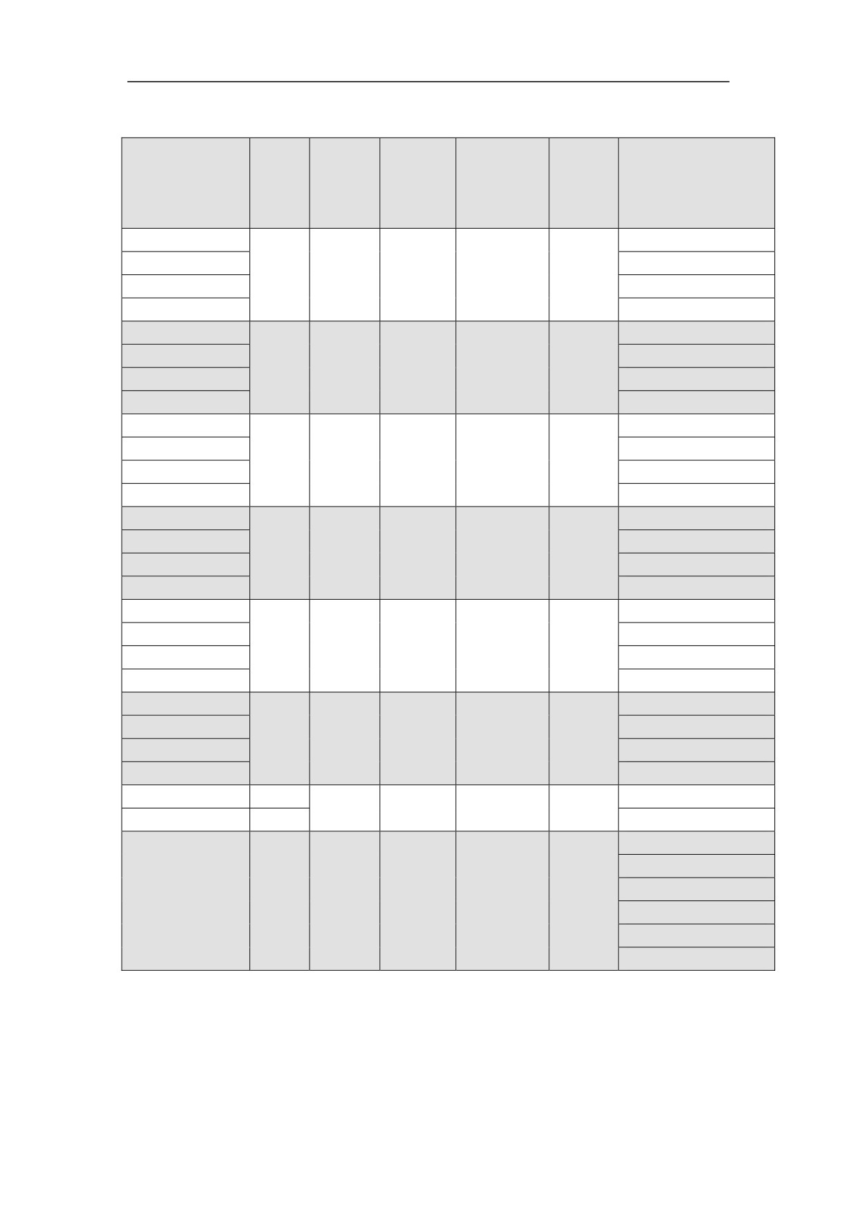
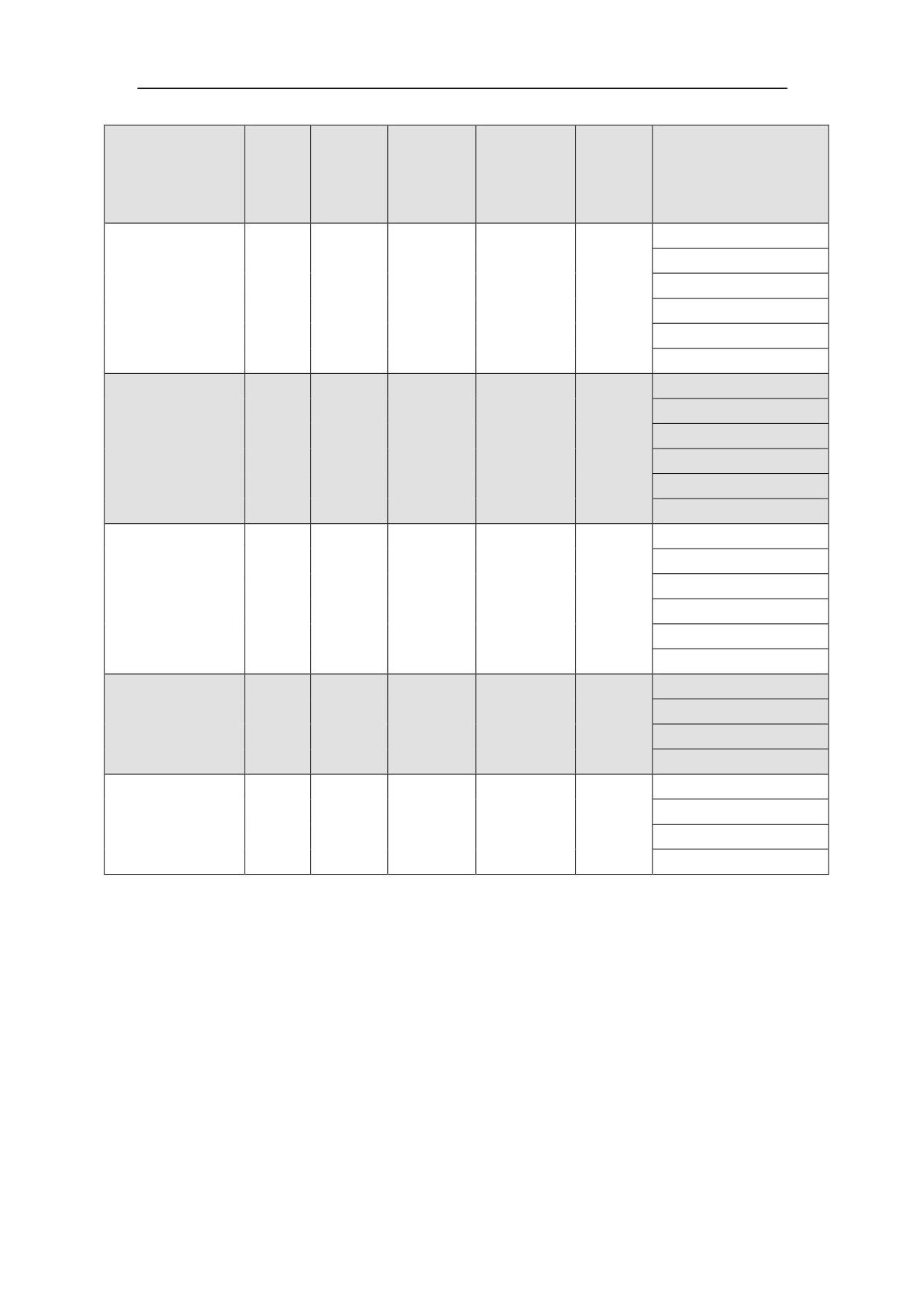
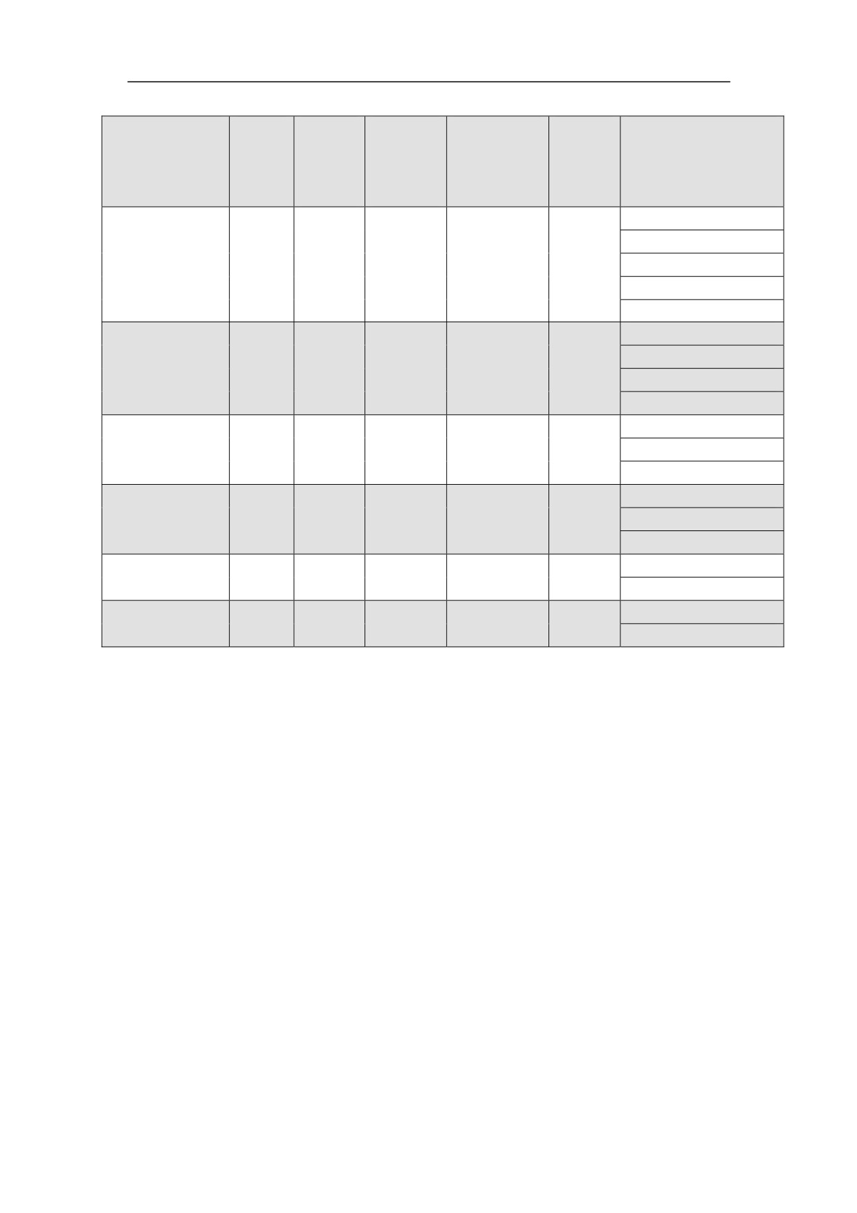
Table 3-4 Technical specification of series GK6 AC permanent magnet servo motor
1. Natural cooling:
Type
Rated
Static
Phase
Rotational
Weight
Adaptive
Speed
Torque
Current
Inertia
Kg
AC Servo
r/min
M0
I0
10¯4Kgm2
Amplifier
Nm
A
/Overload Ratio
GK6062-6AC61
2000
3.8
HSV-180AD-035/5.7
7.5
12.9
12.8
GK6062-6AF61
3000
5.7
HSV-180AD-035/3.8
GK6063-6AC61
2000
5.6
HSV-180AD-035/3.9
11
17
14.5
GK6063-6AF61
3000
8.3
HSV-180AD-035/2.6
GK6065-6AC61
2000
6.2
HSV-180AD-035/3.5
15
23.4
17.8
GK6065-6AF61
3000
9.1
HSV-180AD-035/2.4
GK6072-6AC61
2000
3.8
HSV-180AD-035/5.7
7.5
12.9
12.8
GK6072-6AF61
3000
5.7
HSV-180AD-035/3.8
GK6073-6AC61
2000
5.6
HSV-180AD-035/3.9
11
17
14.5
GK6073-6AF61
3000
8.3
HSV-180AD-035/2.6
GK6075-6AC61
2000
6.2
HSV-180AD-035/3.5
15
23.4
17.8
GK6075-6AF61
3000
9.1
HSV-180AD-035/2.4
GK6080-6AC61
2000
6.8
HSV-180AD-035/3.2
16
26.7
16.5
GK6080-6AF61
3000
10.2
HSV-180AD-050/2.7
GK6081-6AA61
1200
6.1
HSV-180AD-035/3.6
GK6081-6AC61
2000
21
10
35.7
19.5
HSV-180AD-050/2.8
GK6081-6AF61
3000
15
HSV-180AD-075/2.8
GK6083-6AA61
1200
8.1
HSV-180AD-035/2.7
GK6083-6AC61
2000
27
13.3
44.6
22.5
HSV-180AD-075/3.1
GK6083-6AF61
3000
20
HSV-180AD-100/2.8
GK6085-6AA61
1200
9.9
HSV-180AD-050/2.8
GK6085-6AC61
2000
33
16.5
53.5
25.5
HSV-180AD-075/2.5
GK6085-6AF61
3000
24.8
HSV-180AD-100/2.3
GK6087-6AA61
1200
11.1
HSV-180AD-050/2.5
GK6087-6AC61
2000
37
18.5
62.4
28.5
HSV-180AD-075/2.3
GK6087-6AF61
3000
27.8
HSV-180AD-150/3
GK6089-6AA61
1200
12.6
HSV-180AD-050/2.2
GK6089-6AC61
2000
42
21
71.3
31.5
HSV-180AD-100/2.7
GK6089-6AF61
3000
31.5
HSV-180AD-150/2.7
GK6100-8AA61
1200
4.7
HSV-180AD-035/4.6
GK6100-8AB61
1500
5.9
HSV-180AD-035/3.7
18
57.2
21
GK6100-8AC61
2000
7.8
HSV-180AD-035/2.8
GK6100-8AF61
3000
11.7
HSV-180AD-050/2.4
GK6101-8AA61
1200
7.0
HSV-180AD-035/3.1
GK6101-8AB61
1500
8.8
HSV-180AD-035/2.5
27
89.5
26
GK6101-8AC61
2000
11.7
HSV-180AD-050/2.4
GK6101-8AF61
3000
17.5
HSV-180AD-075/2.4
29
Type
Rated
Static
Phase
Rotational
Weig
Adaptive
Speed
Torqu
Curre
Inertia
ht Kg
AC Servo
r/min
e
nt
10¯4Kgm2
Amplifier
M0
I0
/Overload Ratio
Nm
A
GK6103-8AA61
1200
9.4
HSV-180AD-035/2.3
GK6103-8AB61
1500
11.8
HSV-180AD-050/2.4
36
121.5
30
GK6103-8AC61
2000
15.7
HSV-180AD-075/2.7
GK6103-8AF61
3000
23.5
HSV-180AD-100/2.4
GK6105-8AA61
1200
11.7
HSV-180AD-050/2.4
GK6105-8AB61
1500
45
14.5
HSV-180AD-075/2.9
153.5
34
GK6105-8AC61
2000
19.5
HSV-180AD-100/2.9
GK6105-8AF61
3000
30.6
HSV-180AD-150/2.7
GK6107-8AA61
1200
14.3
HSV-180AD-075/2.9
GK6107-8AB61
1500
17.9
HSV-180AD-075/2.3
55
185.5
38
GK6107-8AC61
2000
23.8
HSV-180AD-100/2.4
GK6107-8AF61
3000
35.7
HSV-180AD-150/2.4
GK6109-8AA61
1200
18.5
HSV-180AD-075/2.3
GK6109-8AB61
1500
23.1
HSV-180AD-100/2.4
70
233.5
45
GK6109-8AC61
2000
28.2
HSV-180AD-150/3
GK6109-8AF61
3000
42.3
HSV-180AD-200/2.6
30
2. Forced cooling
Type
Rated
Static
Phase
Rotational
Weight
Adaptive
Speed
Torque
Current
Inertia
Kg
AC Servo
r/min
M0
I0
10¯4Kgm2
Amplifier
Nm
A
/Overload Ratio
GK6100-8SA61
1200
6.0
HSV-180AD-035/3.6
GK6100-8SB61
1500
7.5
HSV-180AD-035/2.9
23
57.2
21
GK6100-8SC61
2000
10.0
HSV-180AD-050/2.8
GK6100-8SF61
3000
14.9
HSV-180AD-075/2.8
GK6101-8SA61
1200
9.3
HSV-180AD-035/2.4
GK6101-8SB61
1500
11.7
HSV-180AD-050/2.4
36
89.5
26
GK6101-8SC61
2000
15.6
HSV-180AD-075/2.7
GK6101-8SF61
3000
23.3
HSV-180AD-100/2.4
GK6103-8SA61
1200
12.5
HSV-180AD-050/2.2
GK6103-8SB61
1500
15.7
HSV-180AD-075/2.7
48
121.5
30
GK6103-8SC61
2000
20.9
HSV-180AD-100/2.7
GK6103-8SF61
3000
31.3
HSV-180AD-150/2.7
GK6105-8SA61
1200
15.6
HSV-180AD-075/2.7
GK6105-8SB61
1500
60
19.3
HSV-180AD-100/2.9
153.5
34
GK6105-8SC61
2000
26.0
HSV-180AD-100/2.2
GK6105-8SF61
3000
40.8
HSV-180AD-200/2.7
GK6107-8SA61
1200
18.2
HSV-180AD-075/2.3
GK6107-8SB61
1500
22.8
HSV-180AD-100/2.5
70
185.5
38
GK6107-8SC61
2000
30.3
HSV-180AD-150/2.8
GK6107-8SF61
3000
45.4
HSV-180AD-200/2.4
GK6109-8SA61
1200
23.8
HSV-180AD-100/2.4
GK6109-8SB61
1500
29.7
HSV-180AD-150/2.8
90
233.5
45
GK6109-8SC61
2000
36.3
HSV-180AD-150/2.3
GK6109-8SF61
3000
54.4
HSV-180AD-300/3
GK61011-8SB61
1500
36.6
HSV-180AD-150/2.3
115
270.7
57
GK61011-8SC61
2000
49
HSV-180AD-200/2.3
HSV-180AD-035/2.9
GK6130-8SW61
500
7.5
GK6130-8SV61
750
11
HSV-180AD-050/2.5
GK6130-8SE61
1000
15
HSV-180AD-075/2.8
75
451
53
GK6130-8SA61
1200
18
HSV-180AD-075/2.3
GK6130-8SB61
1500
23
HSV-180AD-100/2.4
GK6130-8SC61
2000
30
HSV-180AD-150/2.8
31
Type
Rated
Static
Phase
Rotationa
Weight
Adaptive
Speed
Torque
Current
l Inertia
Kg
AC Servo
r/min
M0
I0
10¯4Kgm2
Amplifier
Nm
A
/Overload Ratio
HSV-180AD-035/2.4
GK6131-8SW61
500
9
GK6131-8SV61
750
14
HSV-180AD-075/3
GK6131-8SE61
1000
18
HSV-180AD-075/2.3
90
509
60
GK6131-8SA61
1200
22
HSV-180AD-100/2.5
GK6131-8SB61
1500
27
HSV-180AD-150/3.1
GK6131-8SC61
2000
36
HSV-180AD-150/2.3
HSV-180AD-050/2.3
GK6132-8SW61
500
12
GK6132-8SV61
750
18
HSV-180AD-075/2.3
GK6132-8SE61
1000
24
HSV-180AD-100/2.3
120
664
79
GK6132-8SA61
1200
29
HSV-180AD-150/2.9
GK6132-8SB61
1500
36
HSV-180AD-150/2.3
GK6132-8SC61
2000
48
HSV-180AD-200/2.3
HSV-180AD-075/2.8
GK6133-8SW61
500
15
GK6133-8SV61
750
23
HSV-180AD-100/2.4
GK6133-8SE61
1000
30
HSV-180AD-150/2.8
150
819
98
GK6133-8SA61
1200
36
HSV-180AD-150/2.3
GK6133-8SB61
1500
46
HSV-180AD-200/2.4
GK6133-8SC61
2000
60
HSV-180AD-300/2.8
GK6135-8SW61
500
18
HSV-180AD-075/2.3
GK6135-8SV61
750
27
HSV-180AD-150/3.1
180
975
117
GK6135-8SE61
1000
36
HSV-180AD-150/2.3
GK6135-8SA61
1200
43
HSV-180AD-200/2.6
GK6137-8SW61
500
21
HSV-180AD-100/2.7
GK6137-8SV61
750
32
HSV-180AD-150/2.6
210
1130
135
GK6137-8SE61
1000
42
HSV-180AD-200/2.6
GK6137-8SA61
1200
50
HSV-180AD-200/2.2
32
Type
Rated
Static
Phase
Rotational
Weight
Adaptive
Speed
Torque
Current
Inertia
Kg
AC Servo
r/min
M0
I0
10¯4Kgm2
Amplifier
Nm
A
/Overload Ratio
GK6138-8SW61
500
24
HSV-180AD-100/2.3
GK6138-8SV61
750
36
HSV-180AD-150/2.3
GK6138-8SE61
1000
240
48
1360
148
HSV-180AD-200/2.3
GK6138-8SA61
1200
57
HSV-180AD-300/2.9
GK6138-8SB61
1500
73
HSV-180AD-300/2.3
GK6139-8SW61
500
26
HSV-180AD-100/2.2
GK6139-8SV61
750
39
HSV-180AD-150/2.2
270
1590
160
GK6139-8SE61
1000
52
HSV-180AD-200/2.2
GK6139-8SA61
1200
62
HSV-180AD-300/2.7
GK6180-8SE61
1000
51
HSV-180AD-200/2.2
GK6180-8SA61
1200
250
61
2200
277
HSV-180AD-300/2.7
GK6180-8SB61
1500
76
HSV-180AD-300/2.2
GK6181-8SE61
1000
61.5
HSV-180AD-300/2.7
GK6181-8SA61
1200
300
73.5
2800
300
HSV-180AD-300/2.3
GK6181-8SB61
1500
91.5
HSV-180AD-450/2.4
GK6182-8SE61
1000
72
HSV-180AD-300/2.3
350
3400
323
GK6182-8SA61
1200
86
HSV-180AD-450/2.6
GK6183-8SE61
1000
82
HSV-180AD-450/2.7
400
3900
345
GK6183-8SA61
1200
98
HSV-180AD-450/2.3
33
3.2.6 Installation Dimension of the Motor
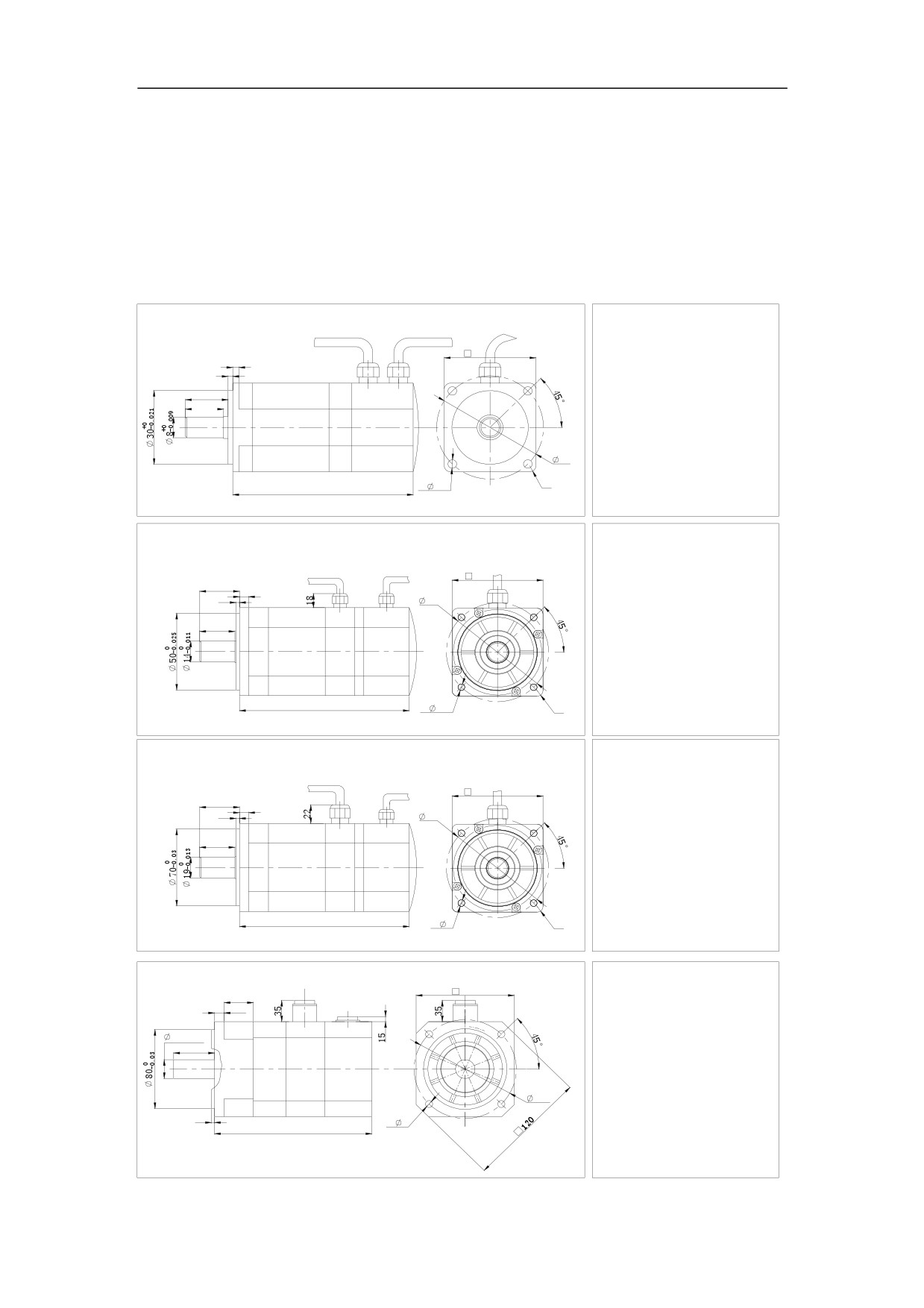
This section describes the installation dimension of series GK6 AC permanent
magnet servo motors.
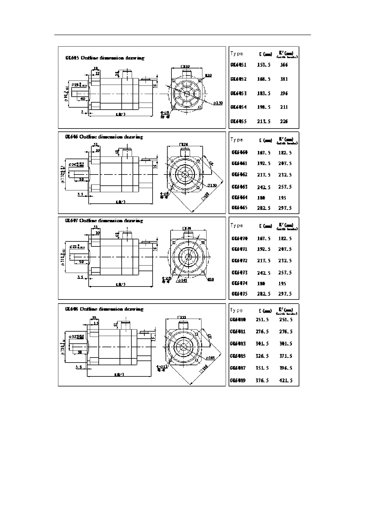
Figure 3-10 Dimension and size of series GK6 AC permanent magnet servo
motors.
GK601 Outline dimension drawing
Type
K
(mm)
40
4
3
GK6011
83.5
25
22.5
GK6013
98.5
GK6015
133.5
46
4-
4.5
R3
K
EQS
GK602 Outline dimension drawing
Type
K(
mm)
K
(mm)
(ZLWK EUDNH)
60
GK6021
110.5
139.5
31
6
3
70
GK6023
120.5
149.5
27
GK6025
140.5
169.5
K(K')
4-
5.7
R4
EQS
GK603 Outline dimension drawing
Type
K
(mm)
K(
mm)
(ZLWK EUDNH)
80
GK6031
149.5
180.5
35
8
3
90
GK6032
169.5
200.5
31
K(K')
4-
6
R5
EQS
Type
(mm)
GK604 Outline dimension drawing
K(mm)
(ZLWK EUDNH
)
96
28
10
GK6040
169.5
176
+0.015
19
+0.002
GK6041
185.5
192
40
GK6042
201.5
208
100
3
4-
7
K(K')
EQS
34
35
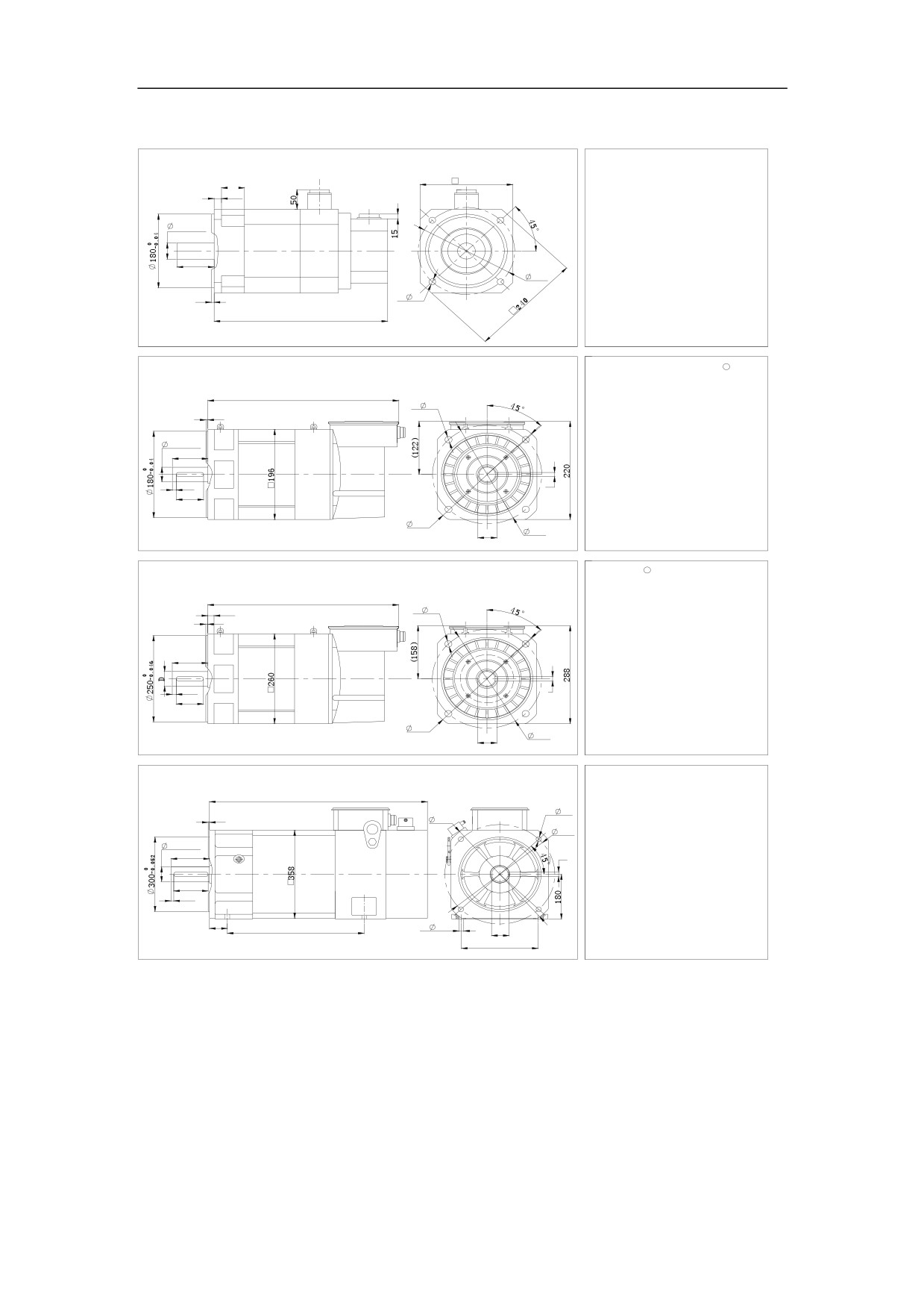
GK610 Outline dimension drawing
Type
K'
(mm)
K
(mm)
(ZLWK EUDNH)
30
192
GK6100
237.5
237.5
18
GK6101
263.5
263.5
38+0.018
+0.002
GK6103
289.5
289.5
80
215
GK6105
315.5
315.5
4
4-
14
EQS
GK6107
341.5
341.5
K(K')
GK6109
380.5
380.5
Type
1
GK610()RUFHG FRROLQJ W\SH) Outline dimension drawing
K
(mm)
GK6100
()25&(')
336.5
K
4-
14
EQS
GK6101
()25&(')
362.5
4
GK6103
()25&(')
388.5
38+0.002
80
GK6105
()25&(')
414.5
GK6107
()25&(')
440.5
5
10
70
()25&(')
GK6109
479.5
249
215
GK61011
()25&(')
531.5
41
Type
1
GK613 Outline dimension drawing
K
(mm)
D(mm)
h(mm)
b(mm)
GK6130
458.5
42
45
12
K
16
4-
18
GK6131
473.5
42
45
12
5
EQS
GK6132
513.5
42
45
12
110
GK6133
553.5
42
45
12
GK6135
593.5
42
45
12
10
b
90
GK6137
633.5
42
45
12
GK6138
658.5
55
59
16
350
h
300
GK61310
683.5
55
59
16
L
K
GK618 Outline dimension drawing
Type
(mm)
(mm)
K
GK6180
359
693
4-
19
5
450
EQS
GK6181
389
723
400
GK6182
419
753
60+0.002
140
18
GK6183
449
783
GK6184
509
843
125
GK6185
569
903
10
GK6186
629
963
GK6187
689
1023
65
L
4-
17
64
GK6188
749
1083
279
GK6189
809
1143
NOTE: After GK610ǃGK613 assembling wellˈtotal length is K+61
36
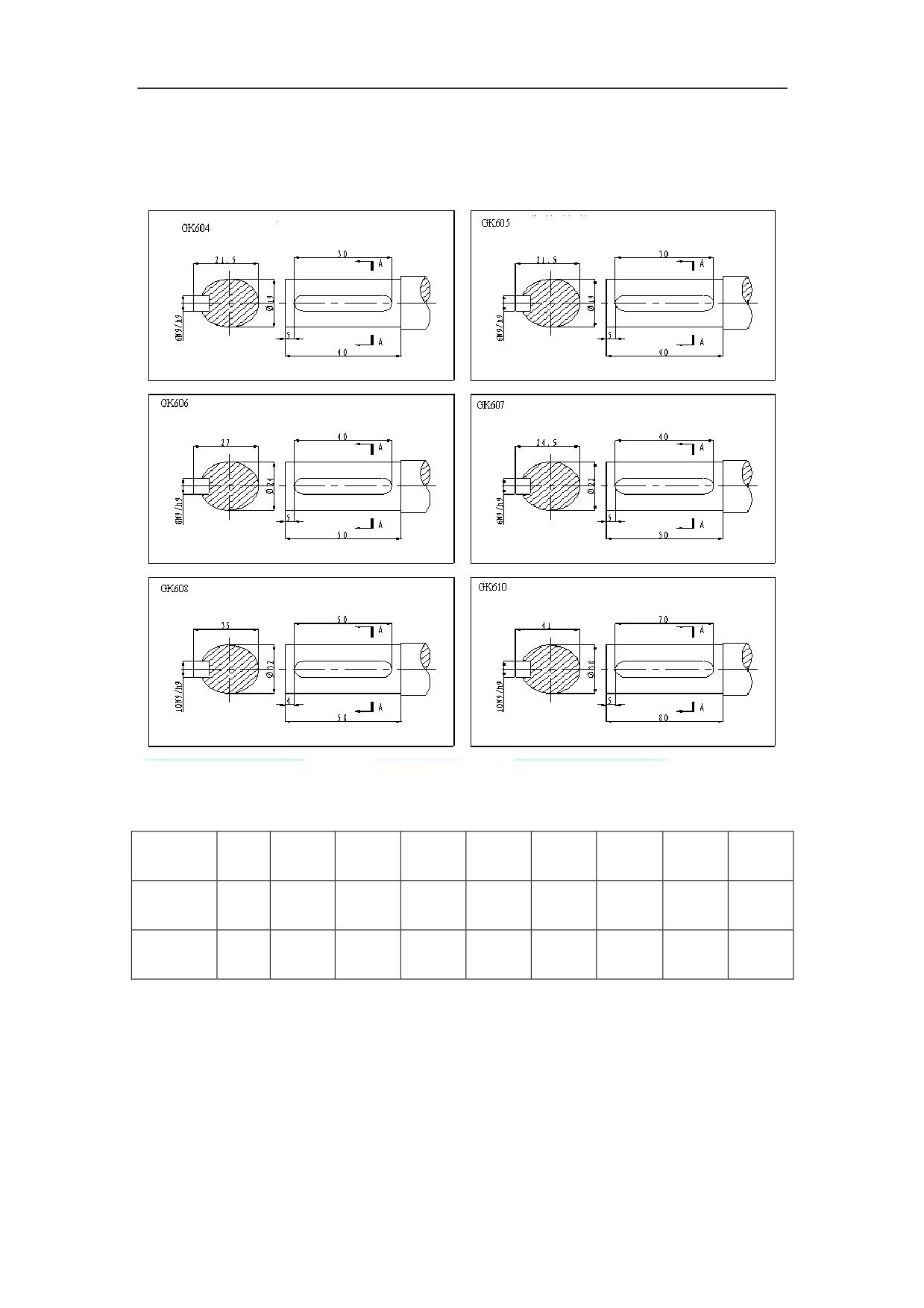
3.2.7Recommended shaft keyway
Figure 3-11 Connect terminal of series GM7 AC servo motor
3.2.8 Recommended C-type center hole
GK6
GK60
GK60
GK60
GK60
GK60
GK61
GK61
GK61
Type
03
4
5
6
7
8
0
3
8
Center
M5
M6
M6
M8
M8
M10
M12
M16
M24
Hole
Thread
12
12
12
14
14
18
22
26
34
Depth
37
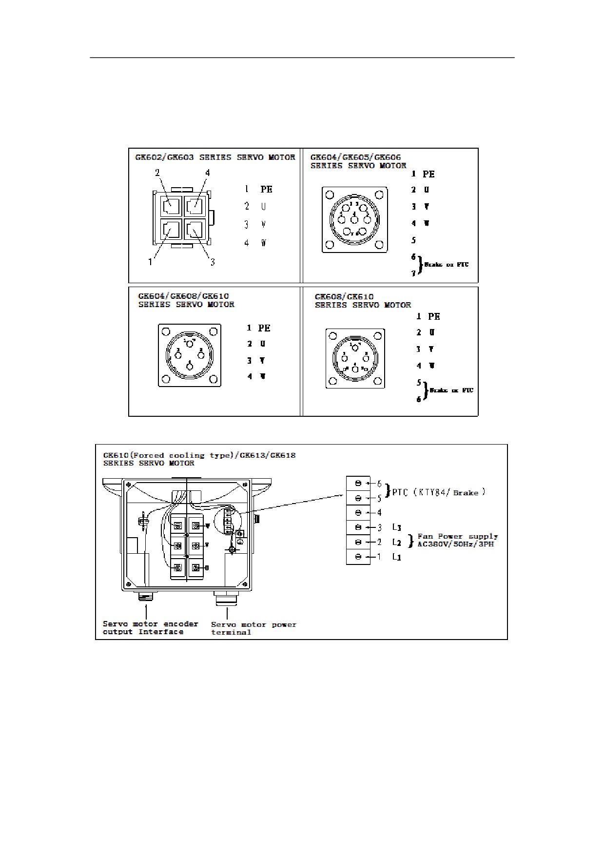
3.2.9 GK6 Series AC permanent magnet servo motor interface
definition
Servo motor power terminal:
Note˖If the motor without the brake or internal thermistor, the corresponding pin is
empty.
38
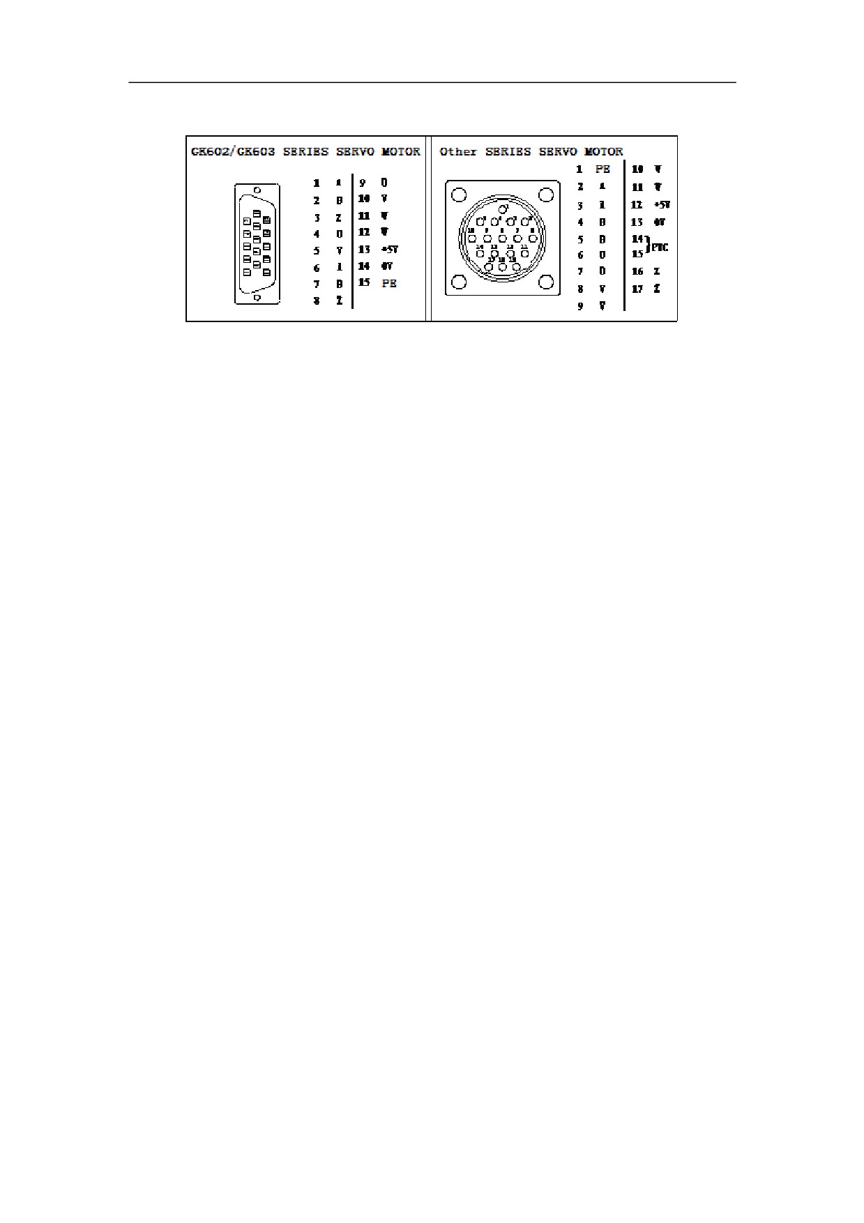
Servo motor encoder output Interface:
39

4 Installation
4.1 Products Check
After receiving products, users must check the items as the following table.
Item
Reference
Whether the product is
Check the product appearance to make sure that the
damaged
product is not damaged during transportation.
Whether the product type
Check and make sure the type of the Servo Servo the
is in accordance with that
Servo Amplifier and motor is in accordance with that
in order
in order
Whether the accessories
Check the packing list and make sure that the
are complete
accessory type and quantity is correct.
Whether the motor shaft
Check and make sure that the motor shaft can be
can be easily turned by
easily turned by hand, except motors with brakes.
hand
If there are any problems, contact directly with the applier or our company.
Warning
ƽ Do not install the Servo Amplifier which are damaged or with incomplete
parts.
ƽ The Servo Amplifier must be matched with the compatible servo motor.
ƽ Do not touch the servo motor shaft directly, which can cause corrosive.
4.2 Installation Environment
4.2.1 Environment Temperature
The working environment temperature is between 0ć to 40ć. If the
temperature over 40ć, de-rating required.
4.2.2 Humidity
Air relative humidity is equal or less than 90%. No condensation.
40
4.2.3 Altitude
The Servo Amplifier must be installed below 1000m altitude. If over 1000m
altitude, de-rating required.
4.2.4 Vibration and Impulsion
The Servo Amplifier is not load bearing and anti-collision. When installing and
working, it must be free from oscillation and impact, and take measures to
control the oscillation below 0.5G˄4.9m/S2˅.
4.2.5 Water
The Servo Amplifier cannot be installed in the water spray or condensation
location.
4.2.6 Air Pollution
The Servo Amplifier must be free from air pollution. It must be installed in the
electric cabinet which is resistant to corrosive and flammable gas, as well as
prevent conductive object, mental dust, oil mist and liquid from entering to the
interior of the equipment.
41
4.3 Installation of Servo Amplifier
Warning
z The Servo Amplifier must be installed in the electric cabinet with fine
protective function.
z The Servo Amplifier must be installed in accordance with the specified
direction and interval to ensure enough cooling.
z The Servo Amplifier cannot be installed near combustibles that may cause fire
hazard.
4.3.1 Installation Methods of HSV-180AD-035,050,075
1.Installation methods
There are three types of wall installation: directly installed without auxiliary devices,
with auxiliary devices, and external heat sink installation. For their installation
diagrams, see Figure 4.-1, Figure 4-2, and Figure 4-3. You can use any of the three
methods, and install the Servo Amplifier vertically.
2.Installation Interval
For the installation interval of single the Servo Amplifier, see Figure 4-4 and Figure
4-5.
For the installation interval of multiple the Servo Amplifier, see Figure 4-6.
During installation, leave enough intervals to ensure good heat emission.
3.Cooling
In the electric cabinet, there must be air blew through the radiator to prevent the
ambient temperature of the Servo Amplifier from overheating.
42
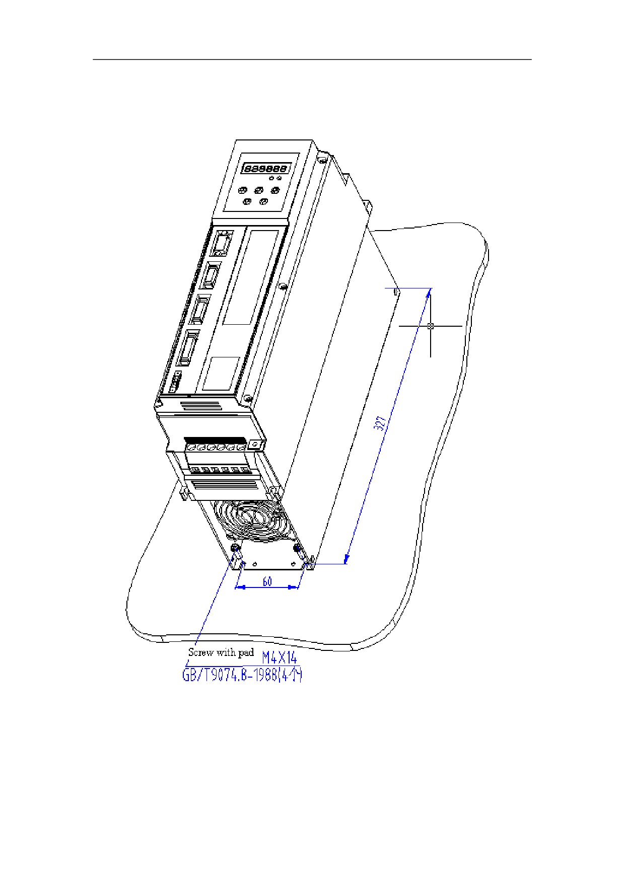
Figure 4-1 Wall installation of HSV-180AD-035, 050, 075 Servo Amplifier (without
auxiliary devices)
43
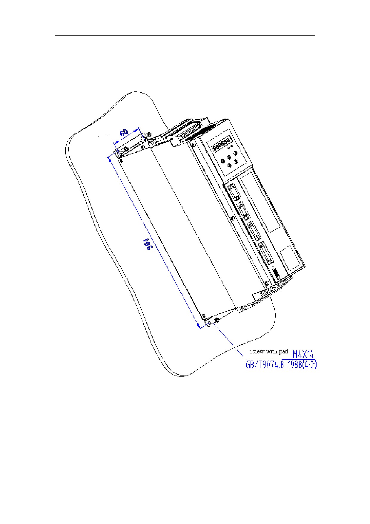
Figure 4-2 Wall installation of HSV-180AD- 035, 050, 075 Servo Amplifier (with
auxiliary devices)
44
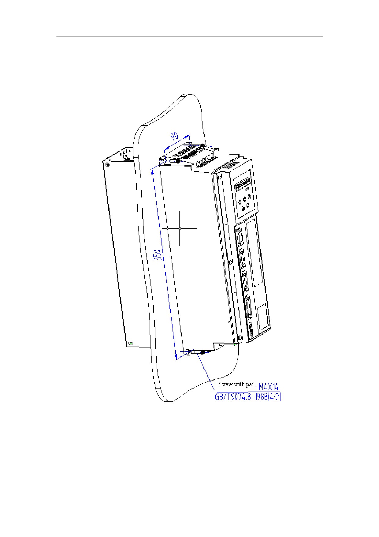
Figure 4-3 Installation diagram of HSV-180AD- 035, 050, 075 (with external heat
sink)
45
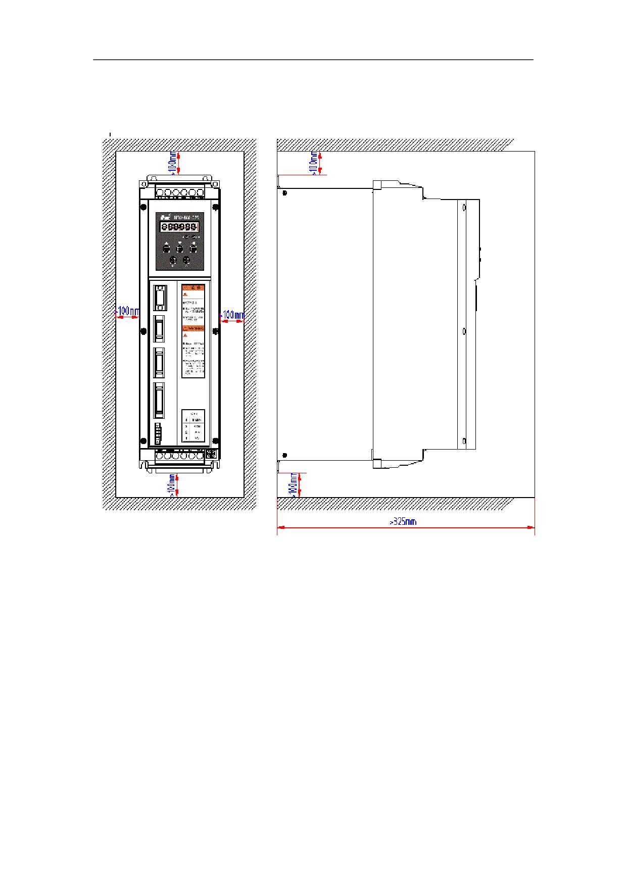
Figure 4-4 Installation interval of HSV-180AD- 035, 050, 075 Servo Amplifier
(Wall installation)
46
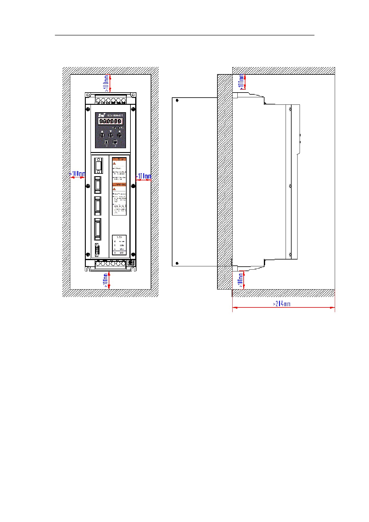
Figure 4-5 Installation interval of HSV-180AD- 035, 050, 075 single Servo Amplifier
47
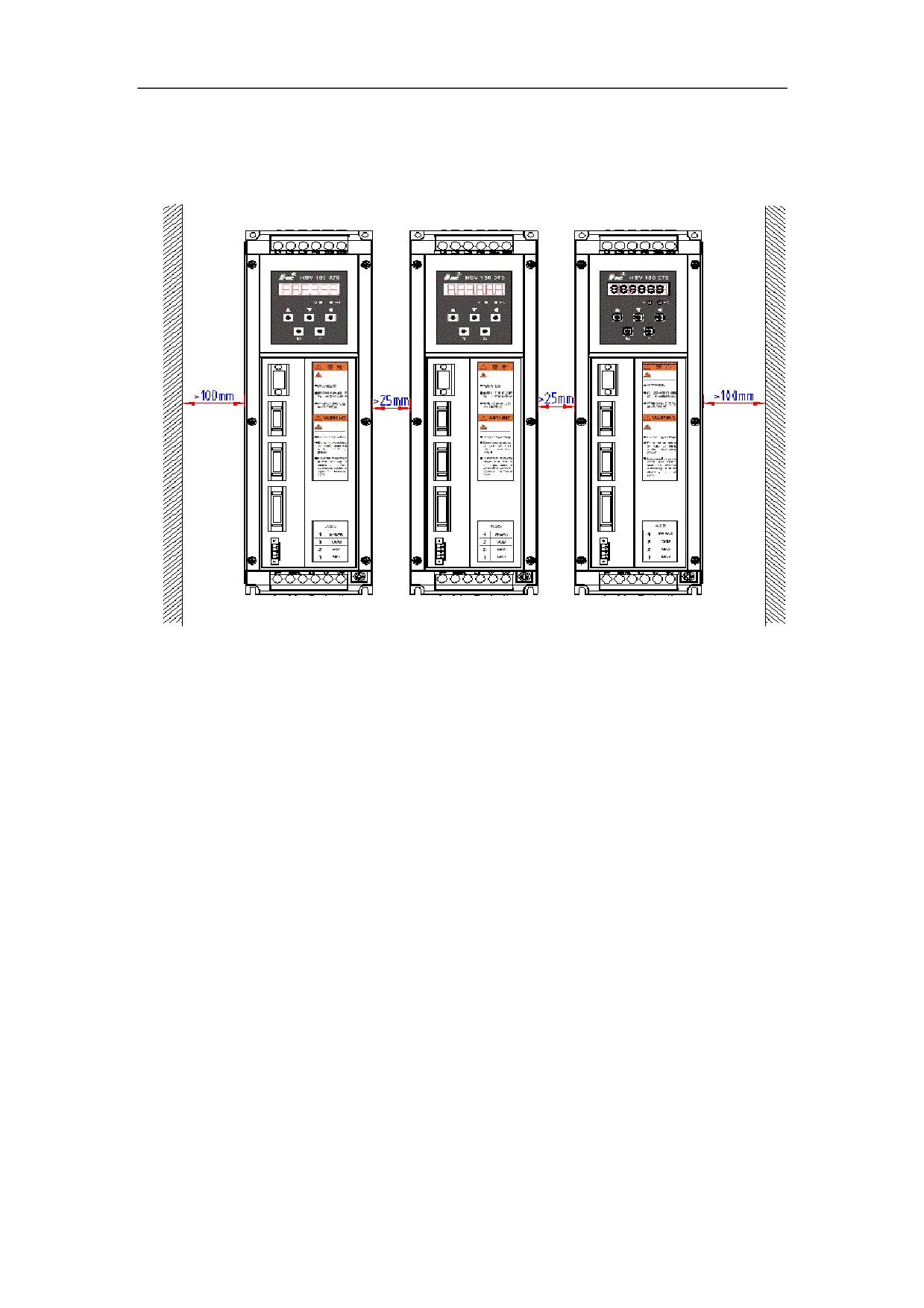
Figure 4-6 Installation intervals of HSV-180AD-035,050,075 multiple Servo
Amplifiers
4.3.2 Installation Methods of HSV-180AD-100,150
1. Installation Methods
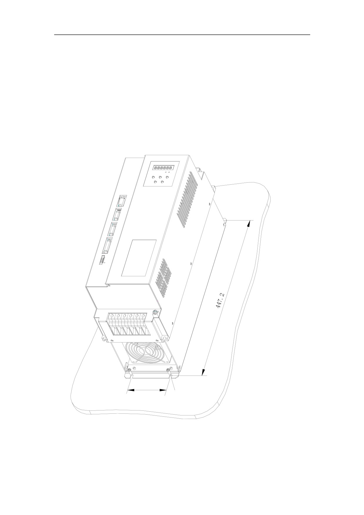
There are two types of wall installation: directly installed with auxiliary devices,
and external heat sink installation. For their installation diagrams, see Figure 4-7,
Figure 4-8.You can use any of the three methods, and install the Servo Amplifier
verticallyDŽ
2. Installation Interval
For the installation interval of single Servo Amplifier, see Figure 4-9 and Figure
4-10
For the installation interval of multiple Servo Amplifier, see Figure 4-11
During installation, leave enough intervals as possible to ensure a good heat
emission.
48
3. Cooling
In the electric cabinet, there must be air blew through the radiator to prevent the
ambient temperature of the Servo Amplifier from overheating.
Figure 4-7 Wall installation diagram of HSV-180AD-100,150 Servo Amplifier
(with auxiliary devices)
LQVWDOO ZLWK
0 h VFUHZV
49