Series HSV-180AD AC Servo Amplifier. User's Manual (V1.00 2012.4) - page 1
CONTENTS
1SAFETY PRECAUTIONS
4
1.1 SYMBOLS OF SAFETY PRECAUTIONS
4
1.2 MEANING OF SAFETY PRECAUTION SYMBOLS
5
1.3 EXPLANATION OF SAFETY PRECAUTION SYMBOLS
5
1.4 SAFETY REGULATIONS
6
2 OVERVIEW
11
2.1 INTRODUCTION
11
2.2 INTRODUCTION TO CONTROL MODES
12
3 ORDER INFORMATION
14
3.1 SPECIFICATIONS OF SERVO AMPLIFIER
14
3.1.1 Specification for HSV-180AD
14
3.1.2 Current Type of HSV-180AD
14
3.1.3 Technical Specification of HSV-180AD
16
3.1.4 Dimension and Size of Servo Amplifier
19
3.2 SPECIFICATION OF SERVO MOTOR
25
3.2.1 Introduction to Series GK6 AC Servo Motor
25
3.2.2 Features of Series GK6 AC Servo Motor
25
3.2.3 Technical index of Series GK6 AC servo motor
26
3.2.4Order information of series GK6 AC Permanent Magnet Servo
28
3.2.5 Technical Specification of Series GK6 AC Permanent Magnet Servo Motor
28
3.2.6 Installation Dimension of the Motor
34
3.2.7Recommended shaft keyway
37
3.2.8 Recommended C-type center hole
37
3.2.9 GK6 Series AC permanent magnet servo motor interface definition
38
4 INSTALLATION
40
4.1 PRODUCTS CHECK
40
4.2 INSTALLATION ENVIRONMENT
40
4.2.1 Environment Temperature
40
4.2.2 Humidity
40
4.2.3 Altitude
41
4.2.4 Vibration and Impulsion
41
4.2.5 Water
41
4.2.6 Air Pollution
41
4.3 INSTALLATION OF SERVO AMPLIFIER
42
4.3.1 Installation Methods of HSV-180AD-035,050,075
42
4.3.2 Installation Methods of HSV-180AD-100,150
48
4.3.3Instllation method of HSV-180AD-200,300,450
53
4.4 INSTALLATION OF SERVO MOTOR
59
1
4.4.1 Installation Environment
59
4.4.2 Installation Method
60
5 WIRING
61
5.1 CONNECTORS
61
5.2 TERMINAL CONFIGURATION
63
5.3 TERMINAL CONFIGURATION
65
5.3.1 Terminals of HSV-180AD-035ˈ050ˈ075ˈ100ˈ150
65
5.3.2 Terminal Configuration HSV-180AD-200,300,450
67
5.3.3 Side wring of main circuit input
68
5.3.4 Control power wiring
70
5.3.5 Output side wiring of main circuit
70
5.4 CONNECTION OF CONTROL SIGNAL TERMINALS
73
5.4.1 XS4 COMMAND input/ output terminals
73
5.4.2 XS5 Input/output Terminal
84
5.5 CONNECTION OF THE ENCODER SIGNAL TERMINAL
85
5.5.1 XS3 ENCODER1 Servo Motor Input Interface
85
5.6 CONNECTION OF THE COMMUNICATION SIGNAL TERMINAL
98
5.6.1 XS1 Serial Interface
98
5.7 WIRING
99
5.8 STANDARD WIRING
100
5.8.1 Standard Wiring for Position Control Mode (Pulse Interface)
101
5.8.2 Standard Wiring for External Speed Control Mode (Analog Interface)
102
5.8.3 Standard Wiring for Closed-loop Control Mode (pulse interface)
105
6. OPERATION AND DISPLAY
107
6.1 OVERVIEW
107
6.2 OPERATION IN THE DISPLAY MODE
108
6.3 STATE SURVEILLANCE MODE
109
6.4 OPERATION IN THE MOVEMENT PARAMETER MODE
111
6.5OPERATION IN THE AUXILIARY MODE
112
6.6 OPERATIONS IN THE CONTROL PARAMETER MODE
114
6.7OPERATION IN THE AUXILIARY MODE
114
6.8 CONTROL PARAMETER SETTING AND SAVING
115
7. PARAMETER SETTING
117
7.1 FUNCTION MENU
117
7.1.1 Parameters illustration
117
7.1.2 Parameter operation instructions
118
7.2 MOVEMENT PARAMETER MODE
119
7.2.1 Movement parameters
119
7.2.2Extension movement parameters
124
7.2.3 Description of the parameter setting:
129
2
7.2.4 Parameters Related to Movement Control
131
7.2.5 Parameters Related to Speed Control Mode
136
7.2.6 Parameters Related to Output Torque Regulation
138
7.2.7 Non standard motor parameter settings
141
7.3 CONTROL PARAMETER MODE
142
7.3.1 Control Parameter
142
7.3.2 Extended control parameters
143
8. OPERATION AND MODIFICATION
145
8.1 POWER CONNECTION
145
8.1.1 Checking Before Running
145
8.1.2 Power On Sequence
146
8.1.3 power connection and alarm sequence
146
8.1.4 Power Off Sequence
149
8.1.5. Alarm Clear
149
8.2 TRIAL OPERATION
150
8.2.1 JOG Running Mode
151
8.2.2 Internal Speed Running Mode
152
8.2.3 External Speed Running Mode (Analog interface)
152
8.2.4 Torque Running Mode (Analog interface)
153
8.2.5 Position Running Mode (Impulse interface)
154
8.2.6 Full closed-loop
154
8.3 RUNNING MODIFICATION
156
8.3.1Basic Gain
156
8.3.2Electrical Gear Setting
157
8.3.3Start and Stop Adjustment
158
9 FAULT TROUBLE SHOOTING
160
9.1 PROTECTION AND FAULT IDENTIFICATION
160
3
1Safety Precautions
Thank you very much for buying AC Servo Amplifier, HSV-180AD AC Servo
Amplifier and servo motor are applicable to the general industrial environment,
not to the strong vibrating environment. Pay attention to the followings:
z It is inapplicable to the medical equipment which related to life safety .
z The Servo Amplifier is not water proof. It must be avoid moisture and direct
sunlight.
z Do not perform any change to the Servo Amplifier and motor.
Before installation and wiring, read through this manual. Before operation,
understand the safety information, safety precautions and operating instruction of
this equipment.
1.1 Symbols of Safety Precautions
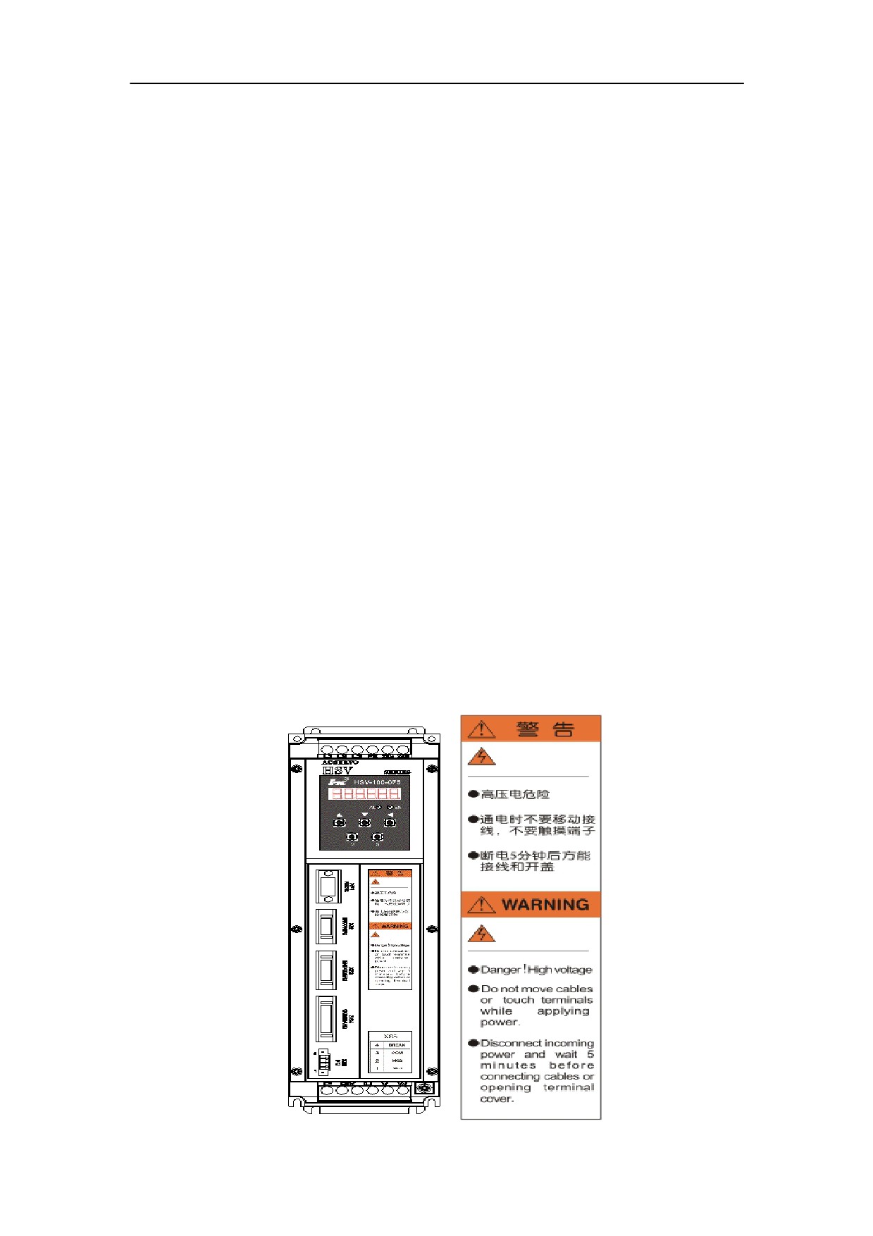
Symbols of safety precautions are displayed on the front panel of the Servo
Amplifier.
Figure 1-1 Symbol of safety precaution for HSV-180AD-035ˈ050ˈ075
4
1.2 Meaning of Safety Precaution Symbols
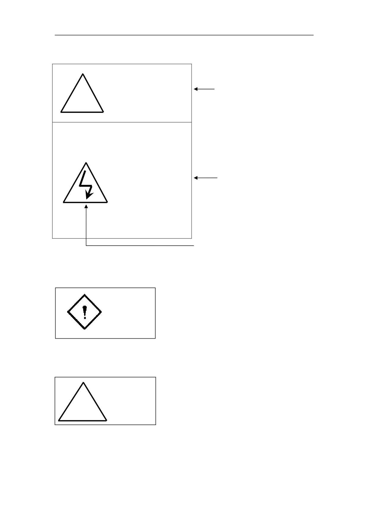
Warning
Safety precaution signage
ʽ
z Danger! High Voltage
z Don’t move cables or
touch terminals while
applying power
z Disconnect incoming
The meaning of each symbol
power and wait
5
minutes
before
connecting cables or
opening
terminal
cover
Symbols of Safety Precaution
1.3 Explanation of Safety Precaution Symbols
Danger
It indicates a potentially hazardous situation which, if not avoided, will result in
death.
Caution
ʽ
It indicates a potentially hazardous situation which, if not avoided, will result in
minor or moderate injury or death and damage to the machine.
5
1.4 Safety Regulations
1. Products Confirmation
Caution
ʽ
Do not install damaged the Servo Amplifier.
Failure to follow this instruction could result in injury.
2. Installation
Caution
ʽ
z Hold the bottom of the machine.
If only hold the panel, the main engine may fall off which may result in
injury.
z Fit to noncombustible such as metal.
Failure to follow this instruction could result in fire hazard.
z If necessary, set a cooling fan and keep the inlet air at 45ć or less.
Overheating may result in fire and other hazards.
z Don’t block the inlet and outlet. Avoid foreign matter entering into the
internal part of the machine.
It may cause the aging of internal components, which can result in
malfunction or fire hazard.
z When installing, make sure a specified intervals between the Servo
Amplifier and control cabinet or other machines.
Failure to follow this instruction could result in fire hazard or malfunction.
6
3. Wiring
Danger
z
Before wiring, confirm whether the power is off.
Failure to follow this instruction could result in electric shock and fire
hazard.
z
Only electrical engineer can do the wiring.
Failure to follow this instruction could result in electric shock and fire
hazard.
z
Make sure the ground terminal grounded.
Failure to follow this instruction could result in electric shock and fire
hazard.
z
After the wiring of the emergency stop circuit, check whether the wiring is
effective.
Failure to follow this instruction could result in injury. (Users shall be
responsible for the wiring.)
z
Do not touch the output terminal directly nor connect external shield to the
output wire of a Servo Amplifier . Avoid short circuit of output wires.
Failure to follow this instruction could result in electric shock and short
circuit.
Caution
ʽ
z Confirm whether the power voltage of the main AC circuit is subject to the
rated voltage of the Servo Amplifier .
Failure to follow this instruction could result in injury and fire hazard.
7
z Do not make withstand test for the Servo Amplifier .
Failure to follow this instruction could result in damage to components such
as semi-conductor.
z Do not connect power cable to the output U, V, W terminals so as to avoid
damage of Servo Amplifier internal parts.
Caution
ʽ
z Do not connect capacitance and LC or LR noise filter to the output circuit so
as to avoid damage of the Servo Amplifier.
z Do not connect electromagnetic switch and electromagnetic contactor to the
U, V, and W output circuit. When the Servo Amplifier running with load,
surging current could activate over-current protection of the Servo
Amplifier .
4. Testing and Commissioning
Danger
z Do not remove or modify anything when the external wirings are made, or
the power is on.
Failure to follow this instruction could result in electric shock.
z Do not approach to the machine on the trial-operations, after resetting of the
Servo Amplifier (Take physical safety into consideration when perform
electrical and mechanical design).
z Arrange an external emergency stop device.
Failure to follow this instruction could result in injury.
8
Caution
ʽ
z Before operating, reconfirm some information such as the use range of the
motor and machines.
Failure to follow this instruction could result in injury.
z Do not touch the machine while operating or just cut off the power, because
the radiator, brake resistor motor etc. may be at high temperature.
Failure to follow this instruction could result in burn.
z If necessary, arrange external brake. Do not touch the machine.
Failure to follow this instruction could result in injury.
z Do not check signal while operating to avoid damage to the equipment.
5. Troubleshooting
Danger
z Do not remove wiring within 5 minutes nor touch terminals after power-off
of the Servo Amplifier , because the high voltage will last for a while.
Failure to follow this instruction could result in electric shock.
z Operations (such as wiring, installation, operation, remove and maintenance)
must be performed by the specified professional personnel.
Failure to follow this instruction could result in electric shock and damage to
the Servo Amplifier .
Caution
ʽ
9
z The control circuit board adopts the CMOS IC. When maintaining, do not
touch it directly with your fingers, because electrostatic induction could
damage the control circuit board.
6. System Configuration
Caution
ʽ
z The rated torque of the servo motor must be larger than continuous effective
load torque. Otherwise, the servo motor could be damaged by long-time
overload operation.
z The ratio of load inertia and servo motor inertia must be less than the
recommended value.
z Make sure that the motor is properly matching the Servo Amplifier .
Failure to follow this instruction could result in damage of the equipment.
7. Others
Danger
z Do not make alterations independently.
Failure to follow this instruction could result in electric shock and injury.
10
2 Overview
Series HSV-180AD AC Servo Amplifier is a new generation of full digital AC
servo amplifier developed by Wuhan Huazhong Numerical Control Co., Ltd..
This product features high performance, compact structure, easy-to-use operation,
and high reliability.
2.1 Introduction
Series HSV-180AD AC Servo Amplifier adopts the latest technologies such as
special motion control digital signal processor (DSP), and intelligent power
module (IPM), and achieves the closed-loop servo control of servo motor. It has
various specifications such as035ǃ050ǃ075ǃ100ǃ150ǃ200ǃ300ǃ450A
and different ranges of power options. Users can configure various types of
Servo Amplifier and AC servo motor to form high reliability and performance
AC Servo Amplifier systems.
Characteristics of Series HSV-180AD AC Servo Amplifier:
1. Easy and flexible operation
By modifying the parameter, you can modify the control methods of the Servo
Amplifier and the interior parameters so as to meet the requirements for different
environment and conditions, and can be compatible with various types of servo
motors.
2. Full display of status
Series HSV-180S provide a series of status display, which enables users to view
related status parameters of the Servo Amplifier during commissioning and
operation. In addition, it provides a range of troubleshooting information.
3. Various interfaces, and flexible control methods
HSV-180AD Servo Amplifier can provide various interfaces and flexible control
methods as follows:
z Pulse input interface
z Analog input interface
11
z Feedback interface of servo motor optical -electrical encoder
z Feedback interface of servo motor encoder
z Serial communication interface
z Programmable I/O interface
4. Servo orientation function
Series HSV-180AD can provide an independent function for servo orientation.
Through feedback devices such as servo motor optic-electrical encoder, servo
encoder and zero switch, it can realize the servo orientation control
independently.
2.2 Introduction to Control Modes
Series HSV-180AD AC Servo Amplifier provides four control modes:
1. Position control mode (pulse interface)
Under this mode, HSV-180AD Servo Amplifier can set to external position
control mode by setting internal parameters. It can receive three types of external
pulse command such as orthogonal pulse command, pulse + direction command,
and positive and negative pulse command.
2. External speed control mode (pulse interface)
Under this mode, HSV-180AD Servo Amplifier can set to external speed control
mode by setting internal parameters. It can receive three types of external pulse
command such as orthogonal pulse command, pulse + direction command, and
positive and negative pulse command.
3. External speed control mode (analog interface)
Under this mode, HSV-180AD Servo Amplifier can set to external speed control
mode by setting internal parameters. It can receives external analog command
with amplitude varies from -10V to 10V or from 0V to 10V.
4. JOG mode
Under this mode, HSV-180S Servo Amplifier can run based on the key setting
(instead of external instruction). This mode is provided for users to test whether
the Servo Amplifier system is correctly installed and connected.
12
5. Internal speed control mode
Under this mode, HSV-180AD Servo Amplifier can run at a present speed in
the system without external instruction. This mode is provided for users to test
whether the Servo Amplifier system is correctly installed and connected.
13
3 Order Information
3.1 Specifications of Servo Amplifier
3.1.1 Specification for HSV-180AD
The following figure shows the specification of HSV-180AD.
Figure 3-1 Current type of HSV-180AD
HSV-180AD
-ƑƑƑ
Servo Amplifier
current type
035
050
075
100
150
200
300
450
3.1.2 Current Type of HSV-180AD
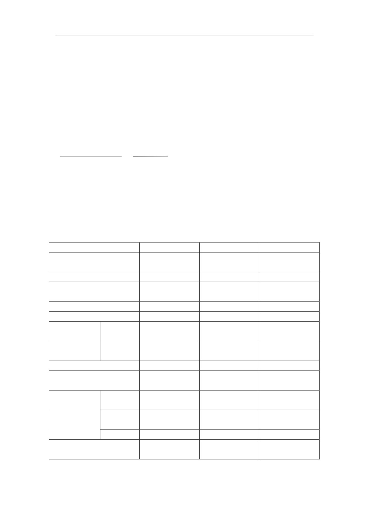
Table 3-1 Current Types of HSV-180AD Servo Amplifier
Type
HSV-180AD-035
HSV-180AD-050
HSV-180AD-075
Maximum power of
3.7KW
5.5KW
7.5KW
applicable Motor˄KW˅
Rated output current (A)
12.5
16
23.5
Short-time Peak Current
22
28
42
(A)
Circute breaker˄A˅
25
32
40
conector˄A˅
18
25
32
Input
Current
10
15
20
exchange
(A)
reactor
Inductance
1.4
0.93
0.7
(mH)
Input filter(A)
10
15
20
Maximum braking resistor
25
25
40
(A)
Resistor
51ȍ
51ȍ
27ȍ
Recommended
(ȍ)
Braking
Power
1500W
1500W
2000W
resistor
(W)
Quanlity
1
1
1
Recomand value of main
4
4
4
circute cable ˄mm2˅
14
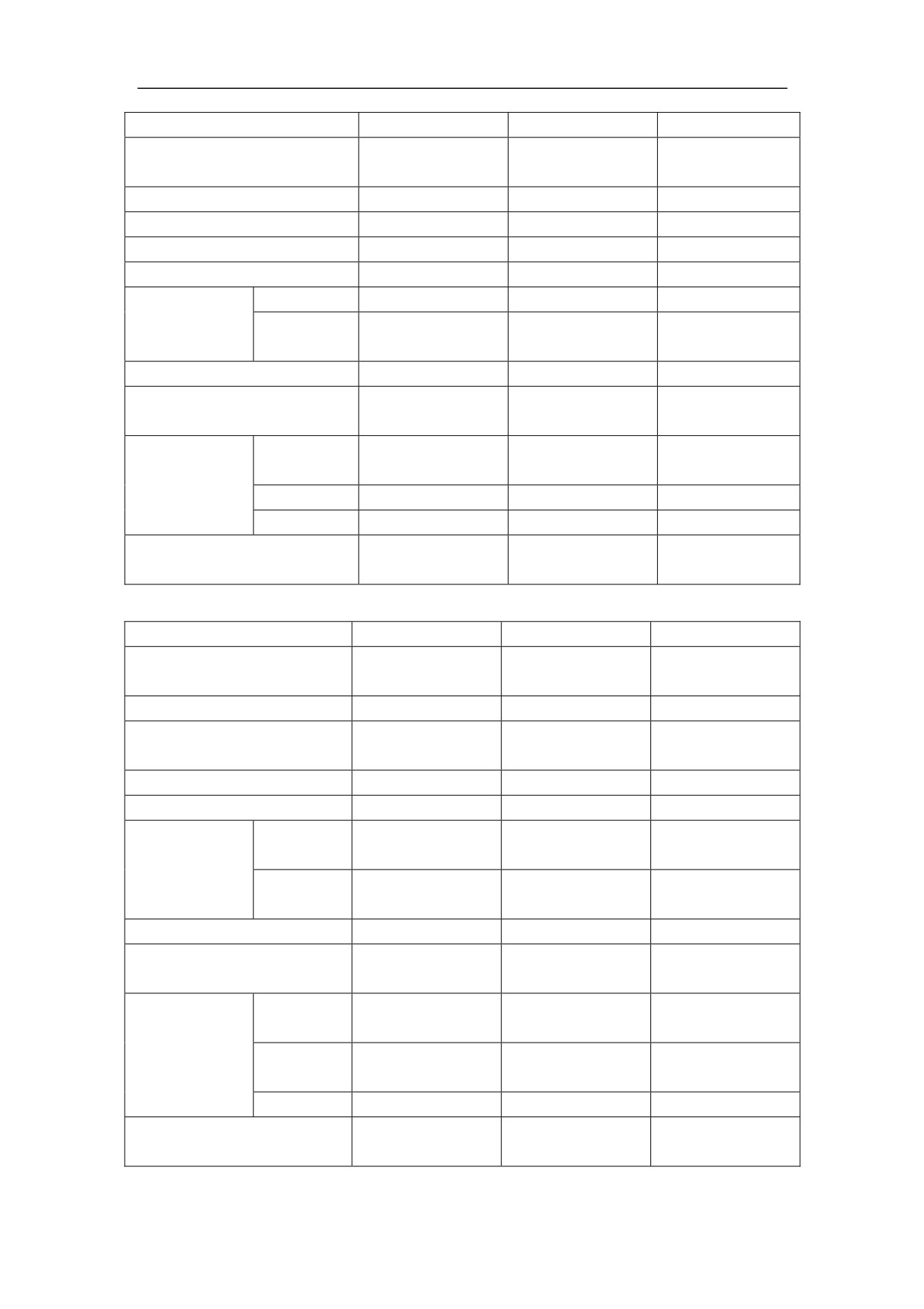
Type
HSV-180AD-100
HSV-180AD-150
Maximum power of
11KW
15KW
applicable Motor˄KW˅
Rated output current (A)
32
47
Short-time Peak Current (A)
56
84
Circute breaker˄A˅
63
100
conector˄A˅
40
63
Input
Current (A)
30
50
exchange
Inductance
0.47
0.28
reactor
(mH)
Input filter(A)
30
50
Maximum braking resistor
50
75
(A)
Resistor
33ȍ
27ȍ
Recommended
(ȍ)
Braking
Power (W)
1500W
2000W
resistor
Quanlity
2
2
Recomand value of main
10
16
circute cable ˄mm2˅
Type
HSV-180AD-200
HSV-180AD-300
HSV-180AD-450
Maximum power of
30KW
37KW
51KW
applicable Motor˄KW˅
Rated output current (A)
64.3
94
128
Short-time Peak Current
110
168
224
(A)
Circute breaker˄A˅
125
200
400
conector˄A˅
95
150
250
Input
Current
80
150
250
exchange
(A)
reactor
Inductance
0.17
0.095
0.056
(mH)
Input filter(A)
80
150
250
Maximum braking resistor
100
100
150
(A)
Resistor
30ȍ
30ȍ
30ȍ
Recommended
(ȍ)
Braking
Power
2500W
2500W
2500W
resistor
(W)
Quanlity
3
4
6
Recomand value of main
35
70
120
circute cable ˄mm2˅
15
3.1.3 Technical Specification of HSV-180AD
The following table describes the technical specification of HSV-180AD
Table 3-2 Technical specification of HSV-180AD Servo Amplifier
Rated
150A and below specifications˖Three-phase AC380V
voltageǃ
-15%̚+10%
50/60Hz
Range of
200A and above Specifications˖
Input
voltage
1.Single phase AC220V control power
-15%̚+10%
power
fluctuation
50/60Hz
Frequency
2.Three-phase AC380V strong power
-15%̚+10%
50/60Hz
Position controlǃExternal speed controlǃJOG controlǃ
Control modes
Internal speed control
Speed
frequency
300Hz or higher
response
Characte
Lower than±0.1 (load 0%̚100%); Lower than±0.2(power
ristic
Speed
supply
volatility
-15%̚+10%)
Speed range
1:10000
Types of
ķ Direction
+ pulse train
②CCW pulse
+CW pulse
pulse
③Two-phase A / B quadrature pulse
command
Form of
Position
pulse
Non-insulated wire drive˄about +5V˅
control
command
Frequency
of pulse
500kHz
command
Types of
ķ Direction
+ pulse train
②CCW pulse
+CW pulse
pulse
③Two-phase A / B quadrature pulse
command
Form of
pulse
Non-insulated wire drive˄about +5V˅
command
Frequency
of pulse
500kHz
Speed
command
control
Electron
1Į/ȕ32767
gear
Analog
DC 0̚+10VorDC -10V̚+10V
command
Acceleratio
n and
1̚32000ms
deceleration
(0~1000r/min or
1000~0r/min)
function
16
TTL composite incremental photoelectric
Type of servo motor
encoder:1024lineǃ2048lineǃ2500 lineǃ6000 line
encoder
Servo encoder encoder
Optical encoder (TTL)
type
Sine and cosine analog signal˄1Vpp˅
Run enable
Alarm clear
Control
Forward and reverse running enable
input
Servo orientation ready
Input and
Control modes switch
output
Indexing incremental orientation ratio input selection
Signal
Servo ready
Servo alarm
Control
Servo orientation-finished
output
Speed-reached
Zero-speed reached
Servo
Accuracy˖±1pulse˗Position adjustment˖Parameter
orientation
setting
Servo
Rigid
Tapping deviation˖±2ˁ
function
tapping
Other
C-axis controlˈThread cutting
function
Communication
RS232 use MODBUS protocol
function
Speed
Flux current
Torque current
Monitoring function
Motor load current
Switch-value input status display
Switch-value output status display
Control mode display
Provides protection against:
Over speed
Main power over-voltage and under-voltage
Over current
Protecting function
Overload
Motor over heat
Big speed error
IPM fault etc.
17
Six LED digital tubes, two light-emitting diodes(LED), five
Operation
bottoms
Adaptive motor
2.2KW̚51KWAC servo motor
Non-corrosive, flammable gas, prevent conductive objects,
Use place
metal dust, oil mist and liquid from entering inside the Servo
Amplifier.
Use
Temperatur
Use temperature :0ć̚+40ćˈMore than 40 ć shall be
e Storage
deratedDŽ
Temperatur
Storage temperature :-20ć̚+60ćDŽ
Use
e
Environ
Use
ment
humidity
Below 90% RH, non-condensing.
Storage
humidity
Altitude
Below 1000mˈAltitude above 1000m shall be deratedDŽ
Vibration /
impact
Vibration Resistance 4.9m/S2 ˈImpact resistance 19.6m/S2
resistance
18
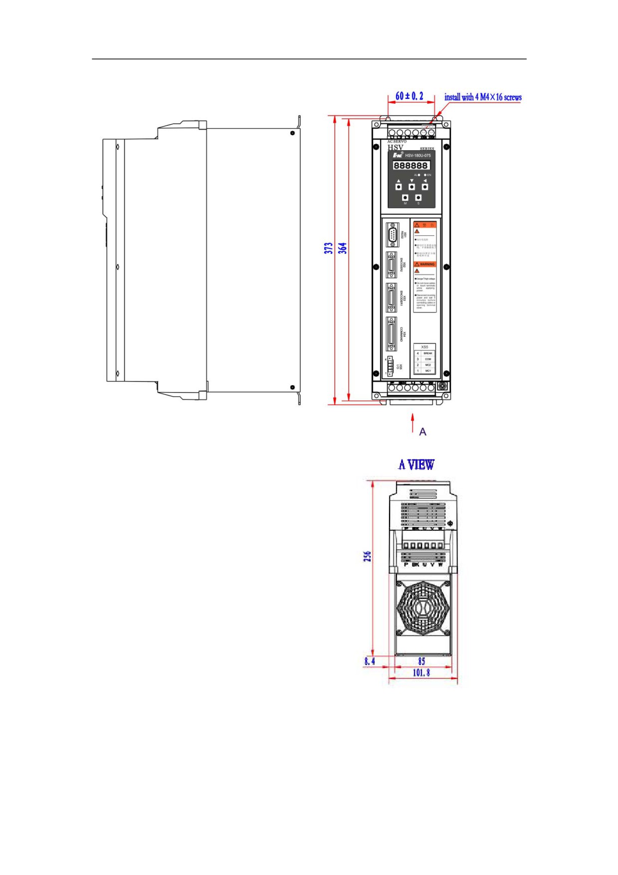
3.1.4 Dimension and Size of the Servo Amplifier
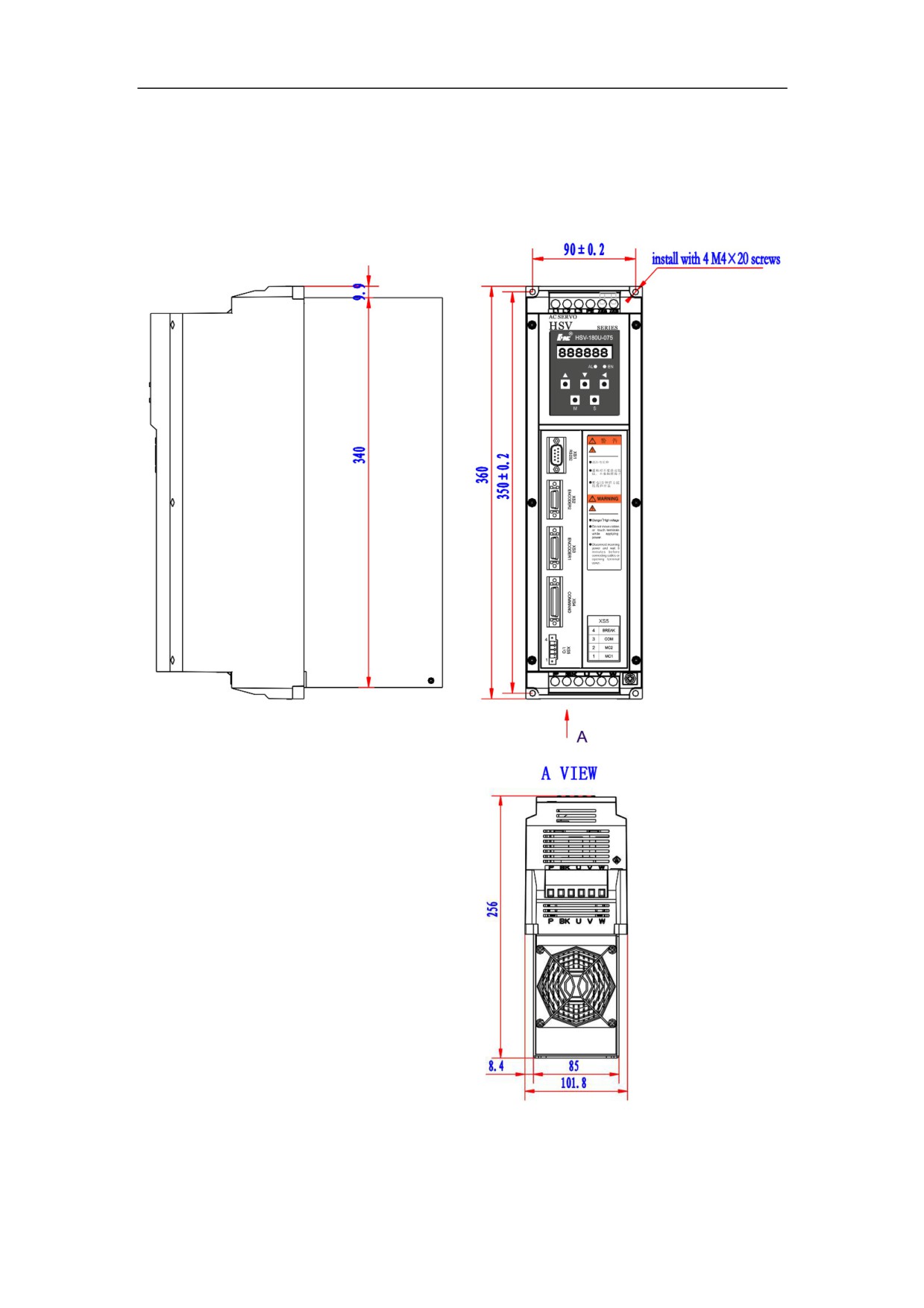
The following figures show the installation dimension of series HSV-180AD
Servo Amplifier.
1ǃFigure 3-2 Dimension and size of HSV-180AD-, 035, 050, 075 (without
auxiliary devices Unit: mm)
2ǃFigure 3-3 Dimension and size of HSV-180AD-035, 050, 075 (with auxiliary
devices Unit: mm)
19
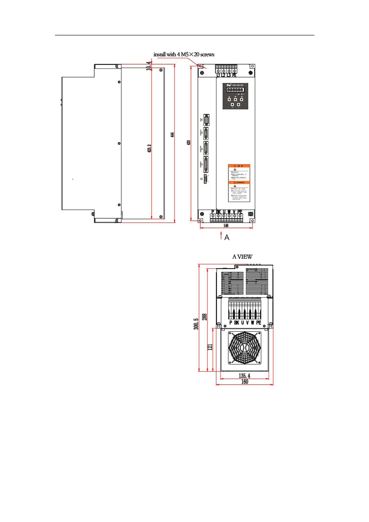
3ǃFigure 3-4 Dimension and size of HSV-180AD-,100, 150 (without auxiliary
devices Unit: mm)
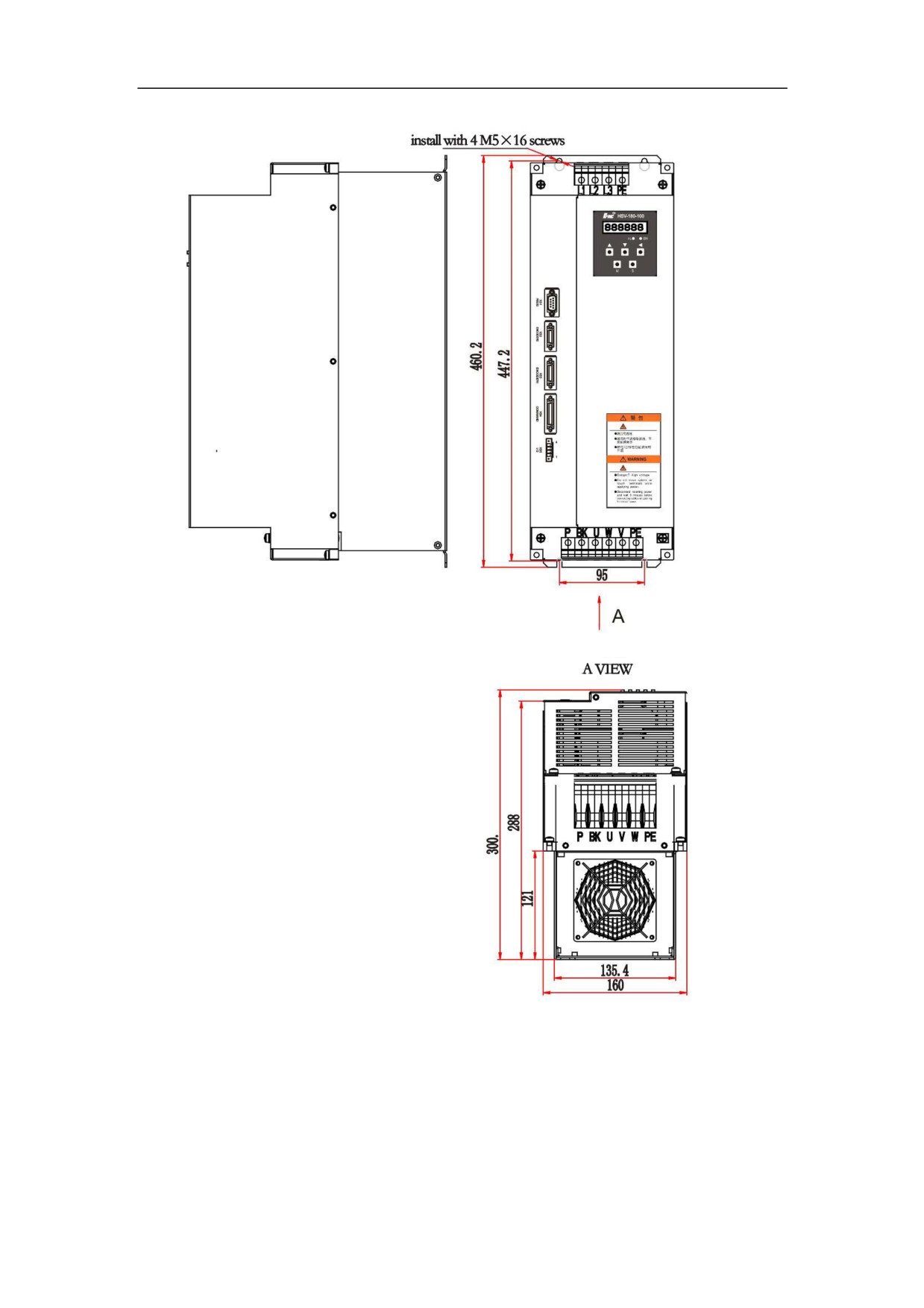
20
4ǃFigure 3-5 Dimension and size of HSV-180AD-100,150 (with auxiliary
devices Unit: mm)
21
22
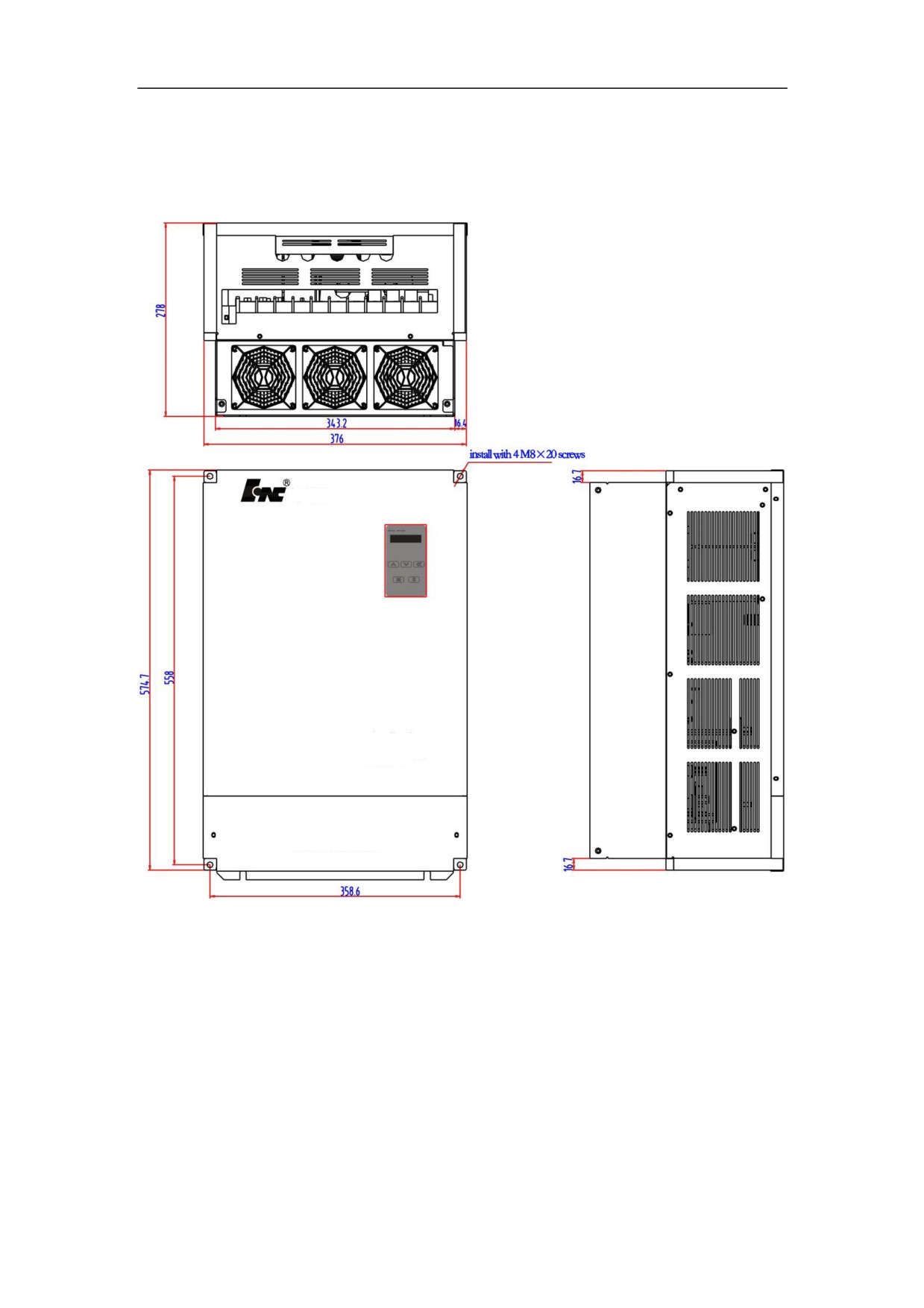
5ǃFigure 3-6 Dimension and size of HSV-180AD-,200, 300,450 (without auxiliary
devices Unit: mm)
23
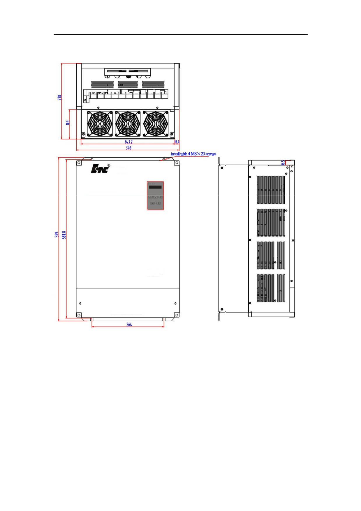
6ǃFigure 3-7 Dimension and size of HSV-180AD-,200, 300,450 (with auxiliary
devices Unit: mm)
24
//////////////////////