Series HSV-180AD AC Servo Amplifier. User's Manual (V1.00 2012.4) - page 4
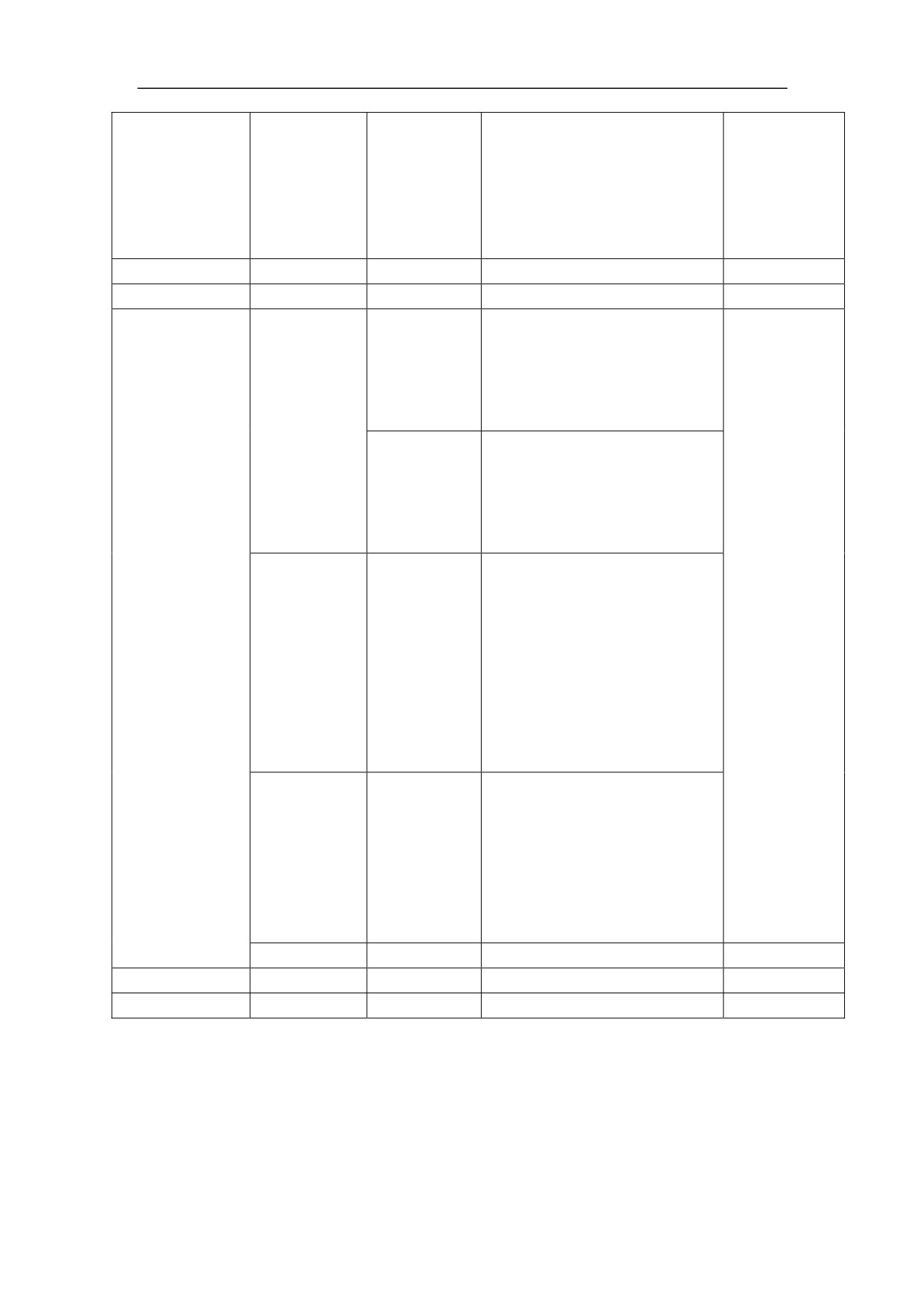
L-CW drive prohibition input
terminal
OFF: indicates that CW drive
6
L-CW
is allowed.
ON: indicates that CW drive
is prohibited.
25
PIN.7
Reserve
26
PIN.8
Reserve
SW output
Position finished output
NPN
signal
Position
terminal
output100mA
finished
When the position error is in
output
the preset range, the signal is
connected.
7 GET
Speed reached output
Speed
terminal
reached
When the speed reaches or
output
exceeds the preset speed, the
signal is connected.
Servo ready output terminal
ON: indicates proper power
supply, and no drive alarm.
The signal is connected.
8
READY
OFF: indicates the main
power is not switched on or a
Servo Amplifier alarm is
reported. The signal is
disconnected.
Servo alarm output terminal
ALM ON: indicates a Servo
Amplifier alarm is reported.
9
ALM
The signal is connected.
ALM OFF: indicates no
Servo Amplifier alarm. The
signal is disconnected.
29
POU.5
Reserve
30
POU.6
Reserve
19,20
COM
75
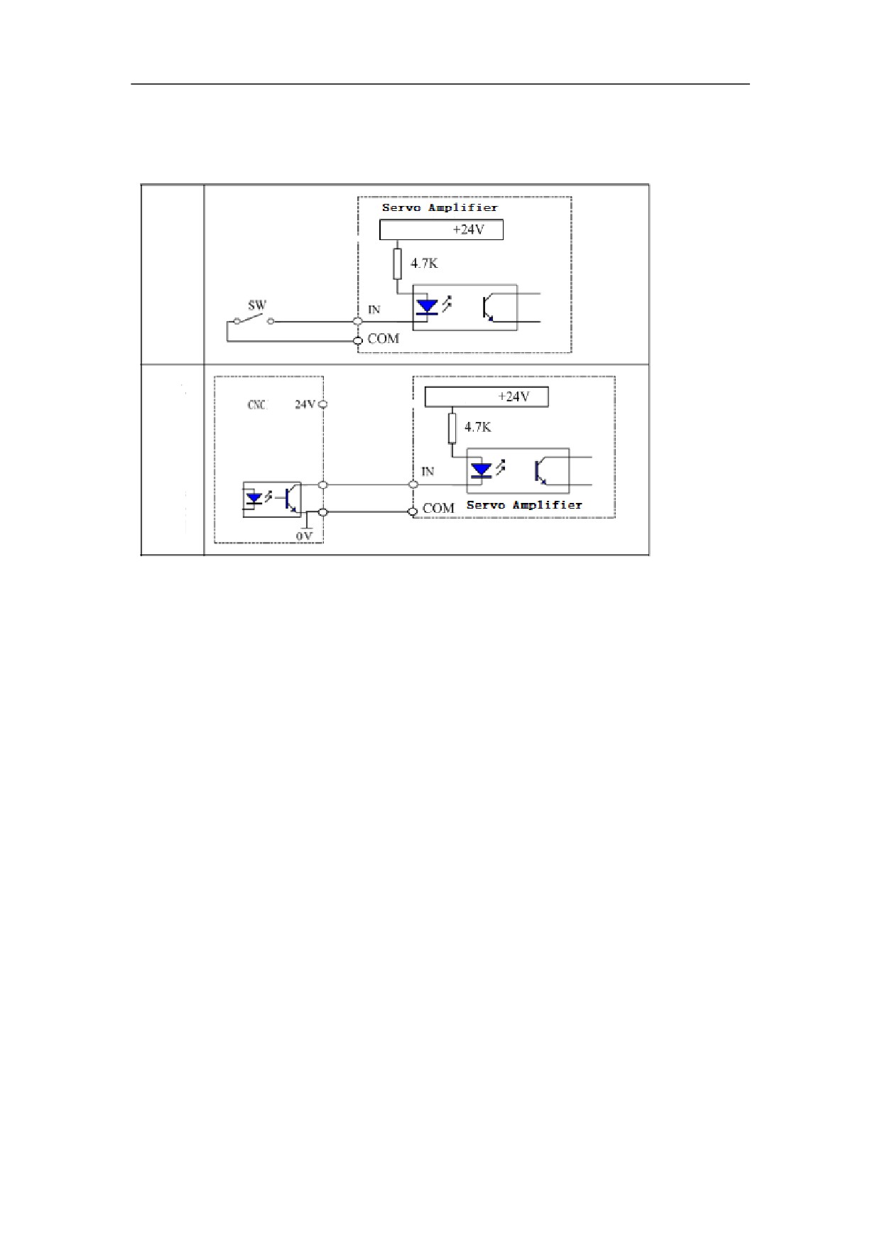
5.4.1.3 XS4 COMMAND Input / Output Interface
1ǃSwitch-value Input Interface
Figure 5-14 Switch-value input interfaces of HSV-180AD
Note:
1ǃ Two common wiring exampleˈIN means input point˖˄ENˈALM_RSTˈ
FWDˈREWˈINC_Sel1ˈINC_Sel2ˈMode_SWˈORN˅
2ǃThe COM signal of the XS4 command input/output interface must be connected to
the power ground of the external DC24V power supply. Otherwise, the Servo
Amplifier may work improperly.
3ǃThe Darlington transistor is served as the output transistor which needs to be
connected to a relay or an optical coupler.The external power supply is provided by
users. Make sure that the polarity is not reversed. Otherwise, it may damage the Servo
Amplifier.
4ǃXS4 command input / output interface of the COM signal must be connected with
the ground signal of external DC24Vˈotherwise Servo Amplifier cannot work
properly.
76
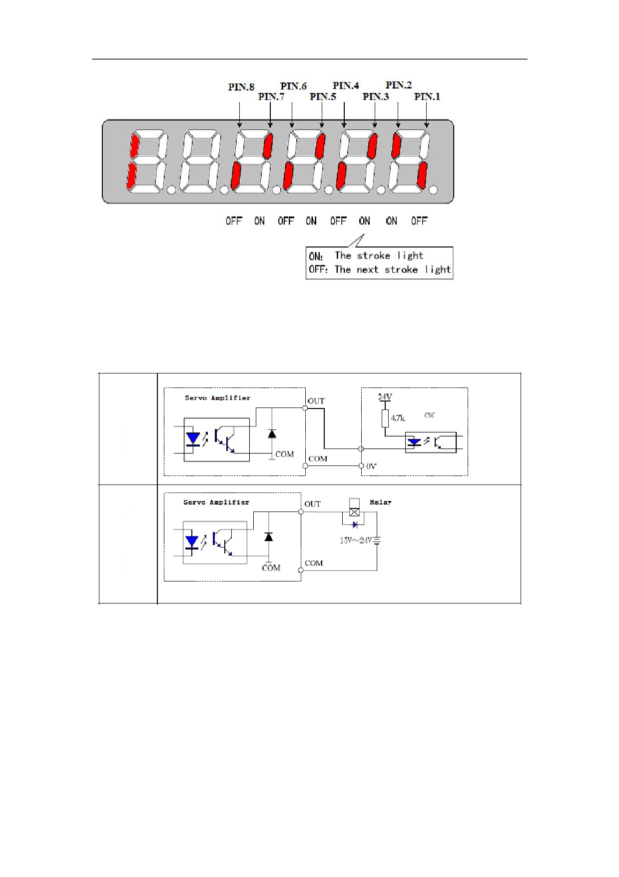
Figure 5-15 Status of switch output signal
2ǃSwitch-value Output Interface
1.Two common wiring exampleˈOUT means out point˖˄ZSPˈREADYˈALMˈ
GETˈORN_FIN˅DŽ
Figure 5-16 Connections of switch output signal
2.Input mode: NPN. The input switch-value state is determined by the Servo
Amplifier. When the input of isolation optical coupler is conducted, the input switch
-value state is ON. When the input of isolation optical coupler is turned off, the input
switch-value state is OFF
77
3.It provides open-collector output, with a maximum of 100 mA current and 25 V
external power supply voltage. Therefore, the load of the switch-value output signal
must meet the requirements. If the value exceeds the maximum value or the output
terminal is directly connected to the power supply, it may damage the Servo
Amplifier.
4.If the load is an inductance load such as relay, it must be anti-parallel with the
freewheeling diode (FWD) at both ends. The FWD cannot be reversed. Otherwise, it
may damage the Servo Amplifier.
5.The output transistor is Darlington Transistor. When it is conducted, the voltage
drop between the collector and the emitter (Vce) is about 1V, which cannot meet the
requirement of the TTL low level. So it cannot be directly connected to the TTL.
3ǃZ-phase Pulse Open Collector Output Interface
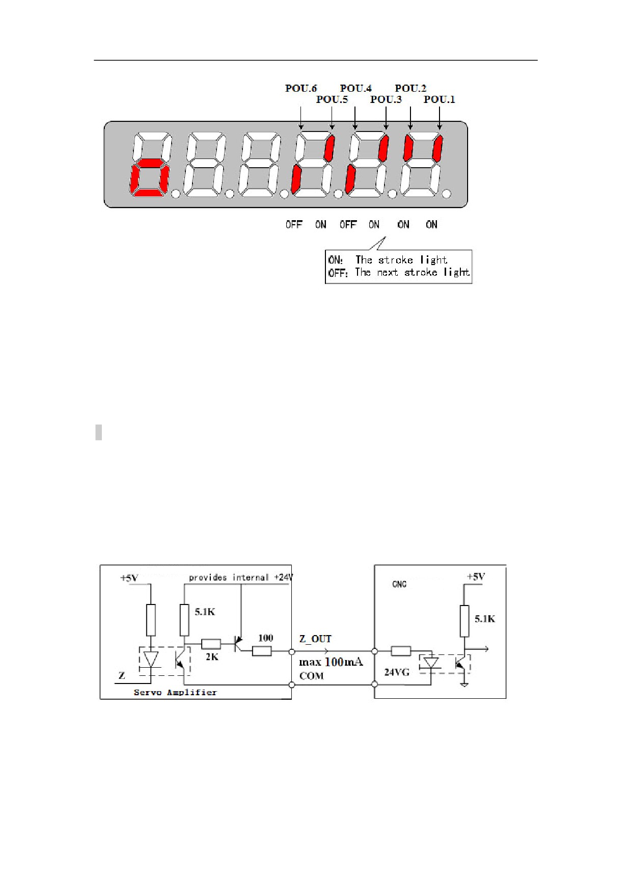
˄1˅Incremental photoelectric encoder Z signal send to the CNC system by open
collectorˈ meanwhile providing two types of output :Z_OUT(PNP)and ZPLS_OUT
˄NPN˅
Figure 5-18Z-phase pulse open-collector output interface˄PNP˅
78
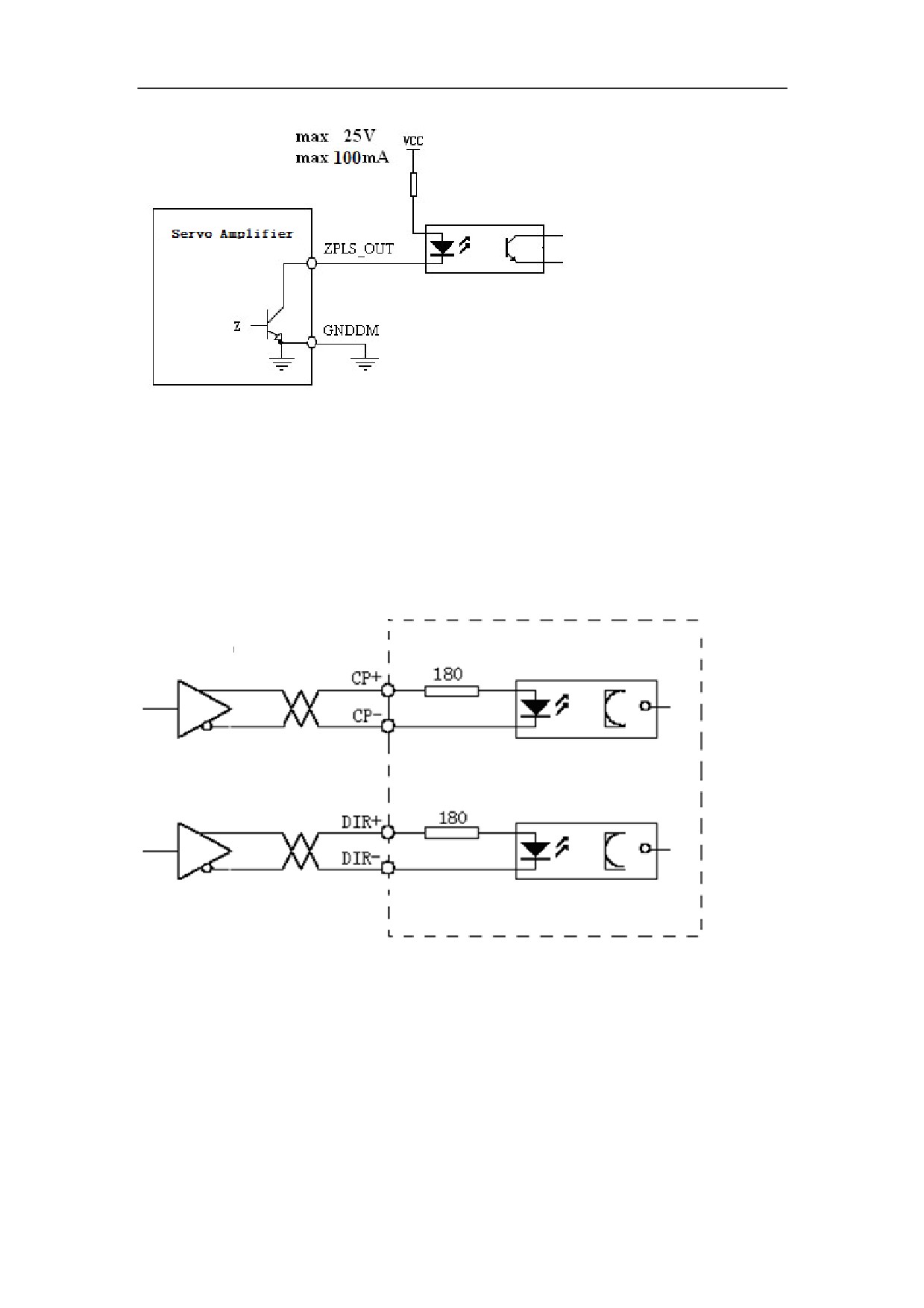
Figure 5-19Z-phase pulse open-collector output interface˄NPN˅
˄2˅Z-phase pulse signal is outputted by the open-collector.ˈwith a maximum of
100mA current
˄3˅The Z-phase pulse signal is usually very narrow. Therefore the PC must use a
high-speed optical coupler receiver, such as 6N137.
˄4˅The output must be non-isolated output (non-insulated).
4ǃ Pulse Command Input Interface
Figure 5-20 Differential drive mode of the pulse input
Figure 5-21 Single-ended drive mode of the pulse input
79
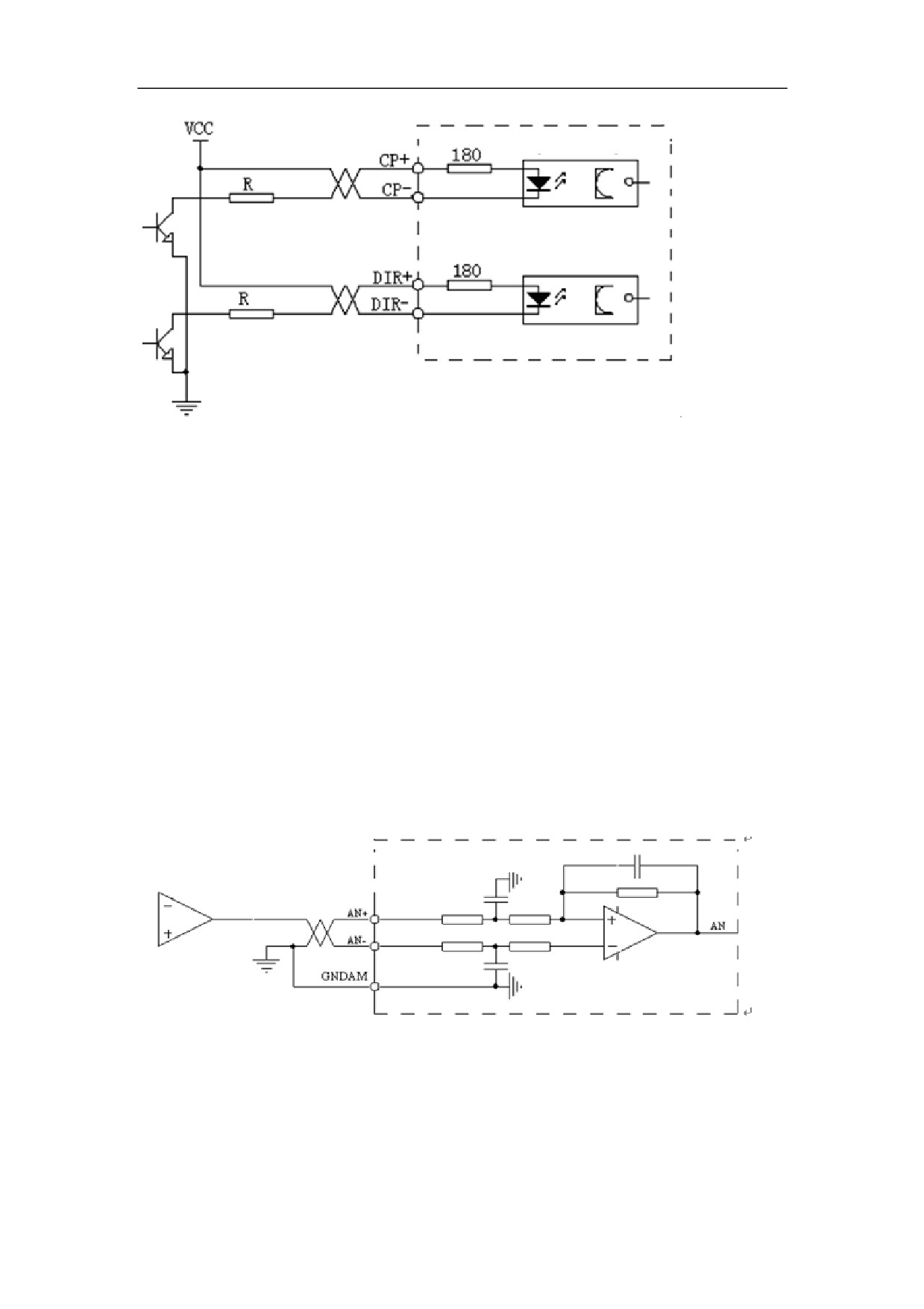
It is recommended that you use the differential drive mode (especially when the cable
is too long) which uses AM26LS31, MC3487 drives or RS422 drives.
The single- ended drive mode can reduce the action frequency. You can determine the
value of R according to a 10 to 15 mA drive current and a maximum of 25V external
power supply voltage.
Generally, if the value of VCC is 24 V, the value of R is 1.3 K to 2 K (VCC = 24 V,
R = 1.3 K to 2 K);
If the value of VCC is 12 V, the value of R is 510 Ω to 820 Ω (VCC = 12 V, R = 510
ȍ to 820 ȍ);
If the value of VCC is 5 V, the value of R is 82 Ω to 120 Ω (VCC = 5 V, R = 82 ȍ to
120 ȍ).
In the single-ended mode, users provide the external power supply. Make sure that the
polarity is not reversed. Otherwise, it may damage the Servo Amplifier.
5ǃ Analog Command Input Interface
Figure 5-22 Differential analog input interface
Figure5-23 Single-ended analog input interface
80
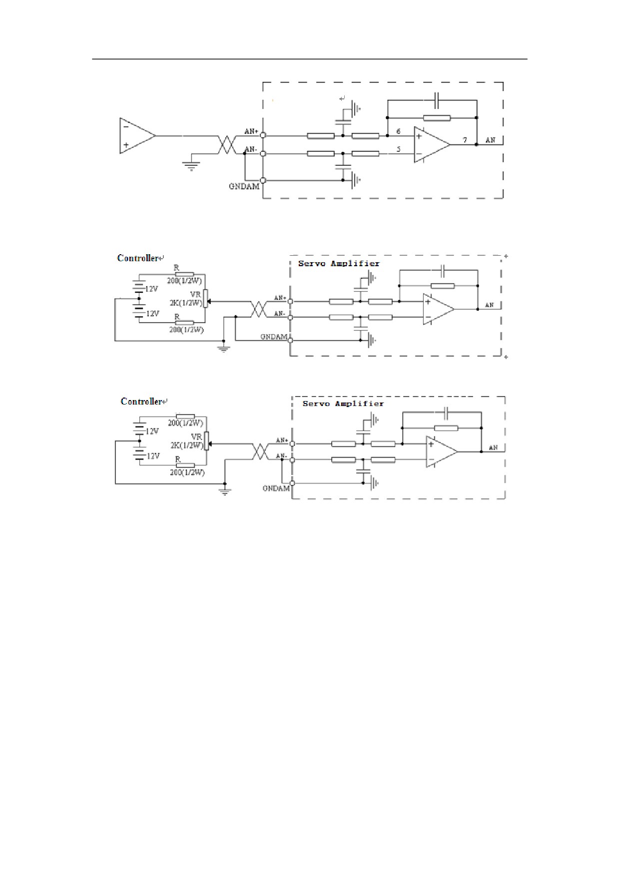
Figure 5-24 c Differential analog potentiometer input interface
Figure 5-25 d Single-ended analog potentiometer input interface
The analog input interface is differential. According to different connection methods,
it has two forms connection, differential connection and single-ended connection. The
range of input voltage is -10V to +10V.
In the differential connection, the analog ground wire is connected to the input
reference terminal at the side of controller. Therefore, it needs three wires to connect
the controller and Servo Amplifier.(see Figure 5-13 a)
In the single-ended connection, the analog ground wire is connected to the input
reference terminal at the side of the Servo Amplifier. Therefore, it needs two wires to
connect the controller and the Servo Amplifier.(see Figure 5-13 b)
The differential connection is superior to the signal-ended connection for its good
anti-common-mode interference characteristic.
The input voltage cannot exceed the range from -10V to +10V. Otherwise it may
damage the Servo Amplifier.
It is recommended that the shield cable be used to reduce the noise disturbance.
It is normal for the analog input interface has a zero bias which can be compensated
by setting the movement parameter PA-8.
The analog interface is non-isolated.
81
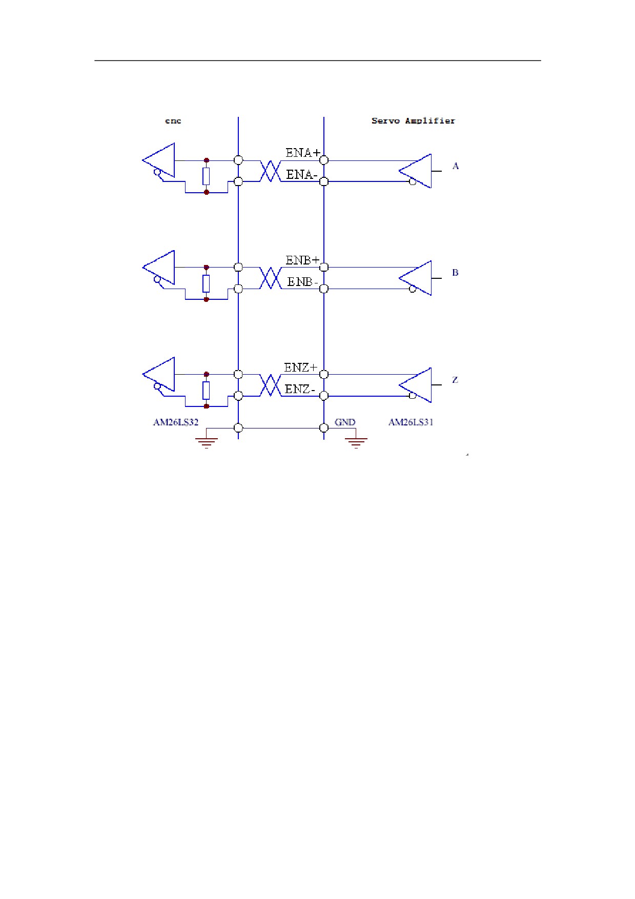
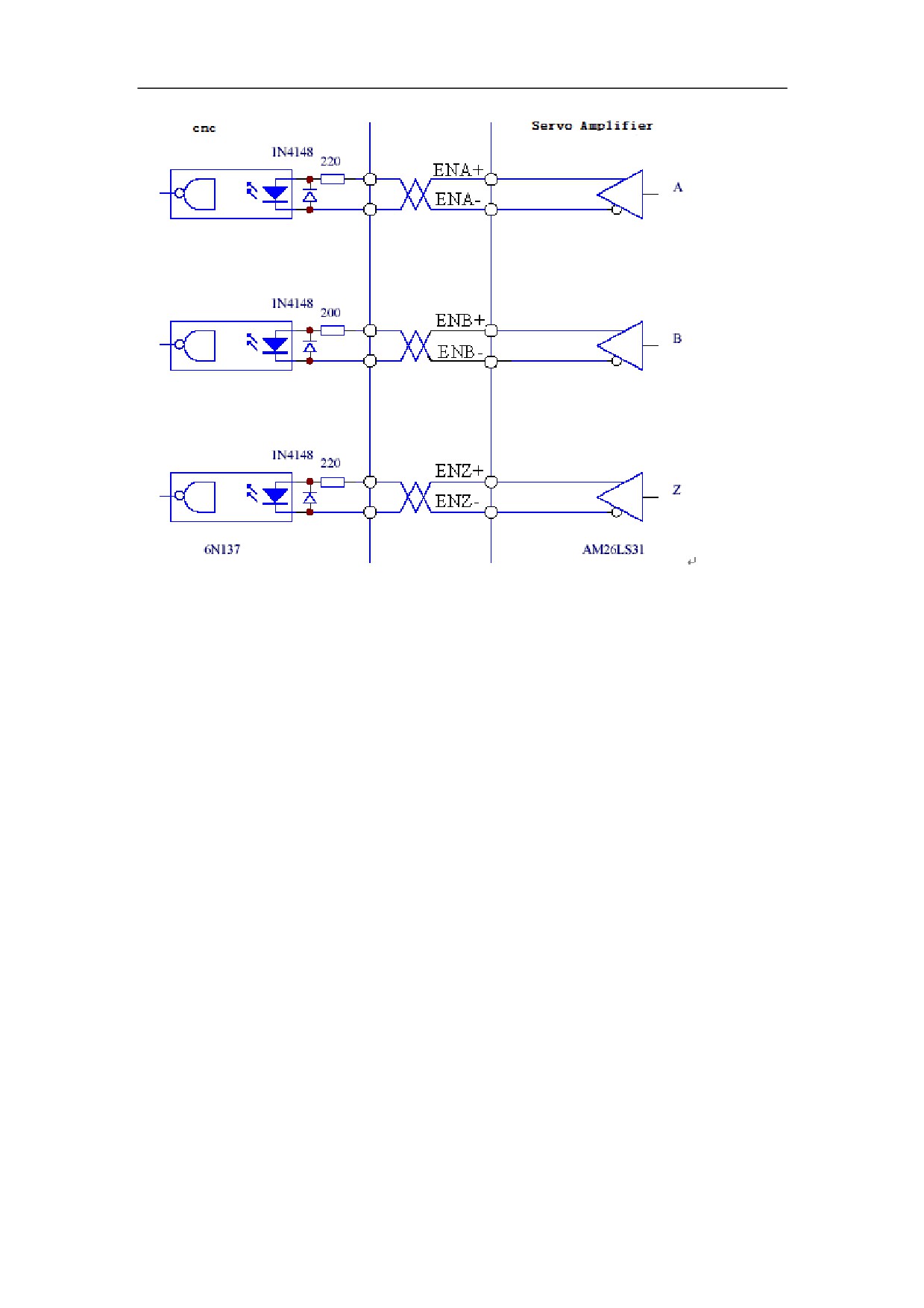
6ǃServo Motor optic-electrical encoder/Servo Encoder Output Interface
Figure 5-26 Servo motor optic-electrical encoder/servo encoder output interface
The encoder signal is outputted by the differential drive˄AM26LS31˅.
The controller input terminal can adopt AM26LS32 receiver and must be connected to
an approximate 330ȍ termination resistor.
The controller ground wire and the Servo Amplifier ground wire must be reliably
connected.
The output must be non-isolated output.
The controller input terminal can also adopt an optical coupler receiver. However, the
receiver must be a high-speed optical coupler, such as 6N137.
Figure 5-27 Servo motor optic-electrical encoder/servo encoder output interface
82
83
5.4.2 XS5 Input/output Terminal
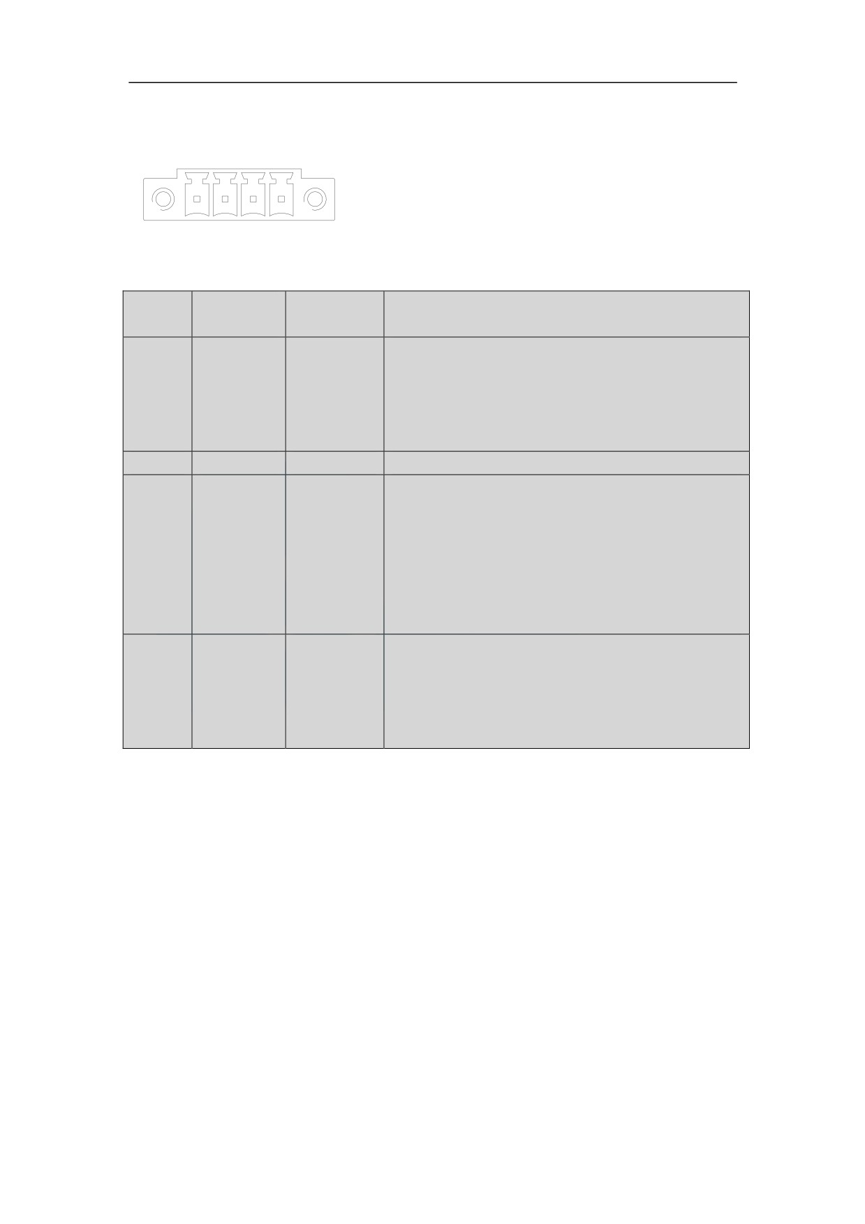
XS5 Input/output Terminal Figure
Figure 5.25 XS5 Input/output Terminal
5.4.2.2 XS5 I/O Input/output Terminal Function
Terminal
NO.
Signal
Description
Symbol
Failure chain output terminal
The relay is connected when the relay is in the
Failure
1
MC1
Normal Open state and the Servo Amplifier runs
chain
properly. The relay is disconnected if there are
any Servo Amplifier faults.
2
MC2
Public terminal connection terminal
If the brake function is required, The COM signal
of the XS4 command input/output interface must
Common
3
COM
be connected to the external DC 24 V power
terminal
ground signal. Otherwise, the Servo Amplifier
may work improperly. Otherwise, the Servo
Amplifier may work improperly.
Brake output terminal
If the main power is proper and no Servo
Brake
4
BREAK
Amplifier fault is reported, the signal is
output
connected after the servo enable signal is input.
Otherwise, the signal is disconnected.
5.4.2.3 XS5 I/O Input/output Terminal Notations
˄1˅If the output terminal of the Servo Amplifier inductive loads, such as
electromagnetic relays, electromagnetic contactor, should be retrofitted surge
suppressor.
The surge suppressors should be nearby installed on end of electromagnetic relay or
electromagnetic contactor coil.
84
5.5 Connection of the encoder signal terminal
5.5.1 XS3 ENCODER1 Servo Motor Input Interface
HSV-180AD support three types of motor encoder: Incremental photoelectric encoder
sine and cosine incremental encoderǃENDAT2.1/2.2of Absolute encoderDŽDetails
are as follows:
1ˊNumber of encoder lines is 1024
Incremental
2ˊNumber of encoder lines is 2048
encoder
3ˊNumber of encoder lines is 2500
4ˊSine and cosine incremental encoder
NDAT2.1/2.2of Absolute encoder
BISS of Absolute encoder
Absolute
encoder
Hiper FACE of Absolute encoder
TAMAGAWA of Absolute encoder
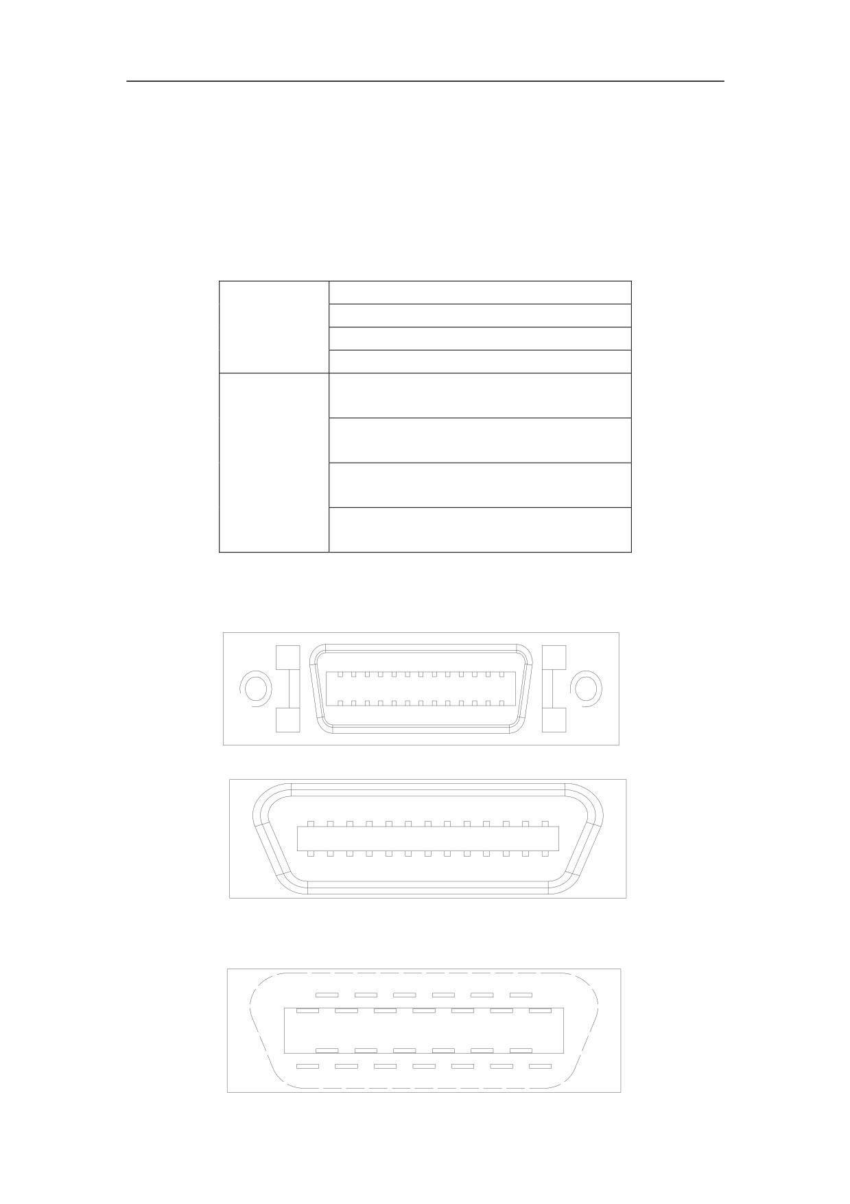
5.5.1.1 XS3 ENCODER1 Servo Motor Input Interface Figure
Figure 5-29 XS3 Servo Motor Input interface plug
Figure 5-30 XS3 Servo Motor Input interface plug (looking from the plug)
Figure 5-31 Soldering terminal of XS3 Servo Motor Input interface plug (looking
from the soldering terminal)
85
5.5.1.2 XS3 ENCODER1 Servo Motor Input Interface Function
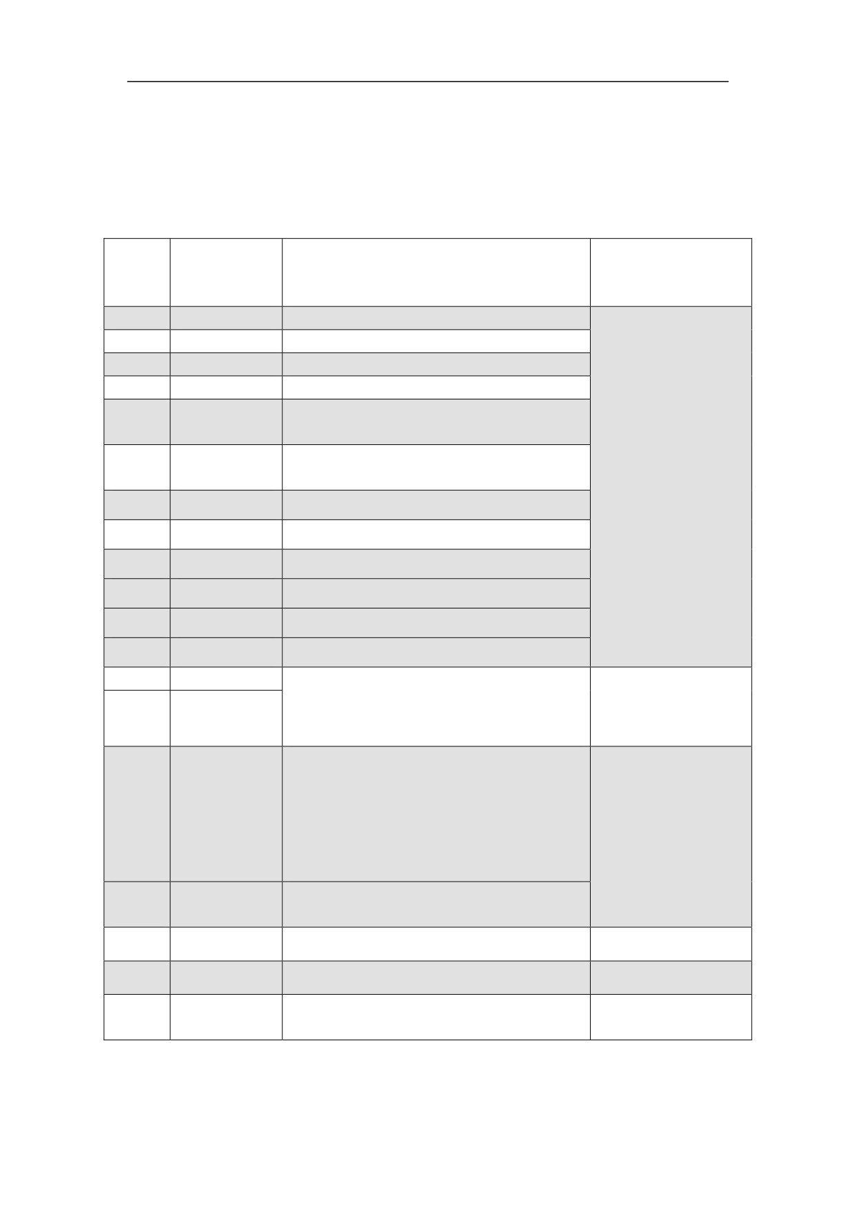
1ǃThe Servo Amplifier connect incremental photoelectric encoder
Chart5.8 signal function of XS3 ENCODER1 connect Incremental photoelectric
encoder
Symbol
Terminal
NO
Function
standard
Symbol
1
A+/SINA+
Servo motor encoder feedback A+ input
2
A-/SINA-
Servo motor encoder feedback A- input
3
B+/COSB+
Servo motor encoder feedback B+input
4
B-/COSB-
Servo motor encoder feedback B- input
Servo motor encoder feedback Z+(or R+)
5
Z+
input
Servo motor encoder feedback Z-(or R-)
6
Z-
Line driver receive
input
RS422 standard
7
U+/DATA+
Servo motor encoder feedback U+ input
8
U-/DATA-
Servo motor encoder feedback U- input
9
V+/CLOCK+
Servo motor encoder feedback V+ input
10
V-/CLOCK-
Servo motor encoder feedback V- input
11
W+
Servo motor encoder feedback W+ input
12
W-
Servo motor encoder feedback W- input
13
OH1
Motor overheat detection input terminal
It is connected to the motor overheat
26
OH2
detection sensor.
Servo motor encoder +5V power output
terminal
16,17
Connect the servo motor optical-electrical
+5V
18,19
encoder with 5 V power supply. If the
DC +5V/150mA
cable is too long, use multiple wires to
form serial connection.
23,24,
GNDD
Servo encoder power ground 0V
25
20,22
Reserved
21
Reserved
Shield ground
14,15
PE
It is connected to the motor housing
NOTE˖The homonyms pin connected has been shorting together in the internal
circuit board
86
2ǃThe Servo Amplifier connect with ENDAT2.1 encoder
Chart5.9 Signal function of XS3 ENCODER1 ENDAT2.1 encoder
Symbol
Terminal
NO
Function
standard
Symbol
1
A+/SINA+
Servo motor encoder feedback A+ input
2
A-/SINA-
Servo motor encoder feedback A- input
3
B+/COSB+
Servo motor encoder feedback B+input
4
B-/COSB-
Servo motor encoder feedback B- input
7
U+/DATA+
Servo motor encoder feedback U+ input
Line driver receive
Servo motor encoder feedback U- input
RS422 standard
8
U-/DATA-
9
V+/CLOCK+
Servo motor encoder feedback V+ input
10
V-/CLOCK-
Servo motor encoder feedback V- input
5,6
Reserved
11,12
Reserved
13
OH1
Motor overheat detection input terminal
It is connected to the motor overheat
26
OH2
detection sensor.
Servo motor encoder +5V power output
terminal
Connect the servo motor
16,17
+5V
optical-electrical encoder with 5 V
18,19
DC +5V/150mA
power supply. If the cable is too long,
use multiple wires to form serial
connection.
23,24,25
GNDD
Servo encoder power ground 0V
20,22
Reserved
21
Reserved
Shield ground
14,15
PE
It is connected to the motor housing
NOTE˖The homonyms pin connected has been shorting together in the internal
circuit board
87
3ǃThe Servo Amplifier connect BISS agreement of Absolute encoder
Chart5.10 Signal function of XS3 ENCODER1 connect BISS agreement of
Absolute encoder
Symbol
Terminal
NO
Function
standard
Symbol
7
U+/DATA+
Servo motor encoder feedback U+ input
8
U-/DATA-
Servo motor encoder feedback U- input
9
V+/CLOCK+
Servo motor encoder feedback V+ input
10
V-/CLOCK-
Servo motor encoder feedback V- input
1,2
Reserved
3,4
Reserved
5,6
Reserved
11,12
Reserved
13
OH1
Motor overheat detection input terminal
It is connected to the motor overheat
26
OH2
detection sensor.
Servo motor encoder +5V power output
terminal
Connect the servo motor
16,17
+5V
optical-electrical encoder with 5 V
18,19
DC +5V/150mA
power supply. If the cable is too long,
use multiple wires to form serial
connection.
23,24,25
GNDD
Servo encoder power ground 0V
20,22
Reserved
21
Reserved
Shield ground
14,15
PE
It is connected to the motor housing
NOTE˖The homonyms pin connected has been shorting together in the internal
circuit board
88
4ǃThe Servo Amplifier connect HIPERFACE agreement of Absolute encoder
Chart5.11 Signal function of XS3 ENCODER1 connect HIPERFACE agreement
of Absolute encoder
Symbol
Terminal
NO
Function
standard
Symbol
1
A+/SINA+
Servo motor encoder feedback A+ input
2
A-/SINA-
Servo motor encoder feedback A- input
3
B+/COSB+
Servo motor encoder feedback B+input
4
B-/COSB-
Servo motor encoder feedback B- input
Line driver receive
7
U+/DATA+
Servo motor encoder feedback U+ input
RS422 standard
8
U-/DATA-
Servo motor encoder feedback U- input
5,6
Reserved
9,10
Reserved
11,12
Reserved
13
OH1
Motor overheat detection input terminal
It is connected to the motor overheat
26
OH2
detection sensor.
Servo motor encoder +9V power output
terminal
Connect the servo motor
16,17
+9V
optical-electrical encoder with 5 V
18,19
DC +9V/150mA
power supply. If the cable is too long,
use multiple wires to form serial
connection.
23,24,25
GNDD
Servo encoder power ground 0V
20,22
Reserved
21
Reserved
Shield ground
14,15
PE
It is connected to the motor housing
NOTE˖The homonyms pin connected has been shorting together in the internal
circuit board
89
5ǃThe Servo Amplifier connect TAMAGAWA agreement of Absolute encoder
Chart5.12 Signal function of XS3 ENCODER1 connect TAMAGAWA
agreement of Absolute encoder
Symbol
Terminal
NO
Function
standard
Symbol
7
U+/DATA+
Servo motor encoder feedback U+ input
8
U-/DATA-
Servo motor encoder feedback U- input
Reserved
9
Reserved
10
1,2
Reserved
3,4
Reserved
5,6
Reserved
11,12
Reserved
13
OH1
Motor overheat detection input terminal
It is connected to the motor overheat
26
OH2
detection sensor.
Servo motor encoder +5V power output
terminal
16,17
Connect the servo motor optical-electrical
+5V
18,19
encoder with 5 V power supply. If the
DC +5V/150mA
cable is too long, use multiple wires to
form serial connection.
23,24,
GNDD
Servo encoder power ground 0V
25
20,22
Reserved
21
Reserved
Shield ground
14,15
PE
It is connected to the motor housing
NOTE˖The homonyms pin connected has been shorting together in the internal
circuit board
90
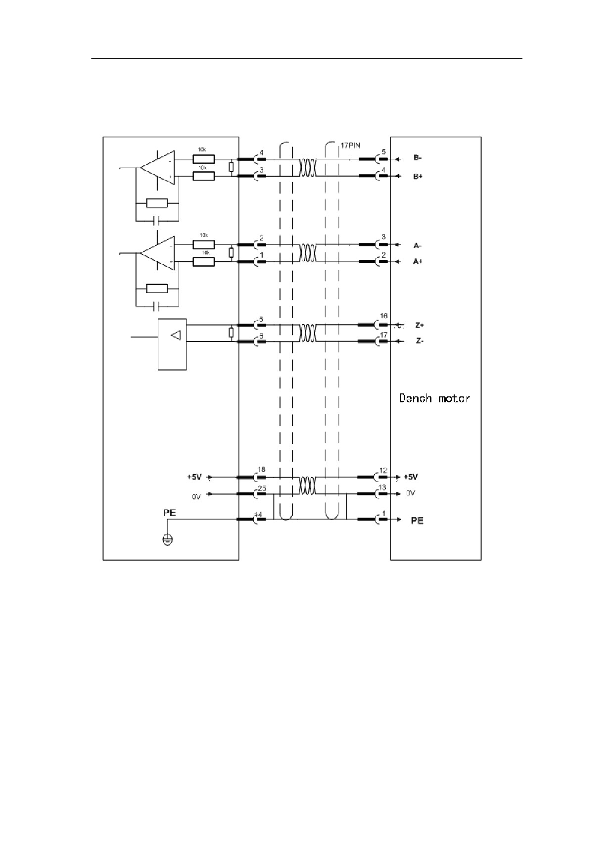
5.5.1.3 XS3 ENCODER1 servo motor encoder input interface wiring diagram
1ǃServo Amplifier connect with Incremental photoelectric encoder and
Dench motor
91
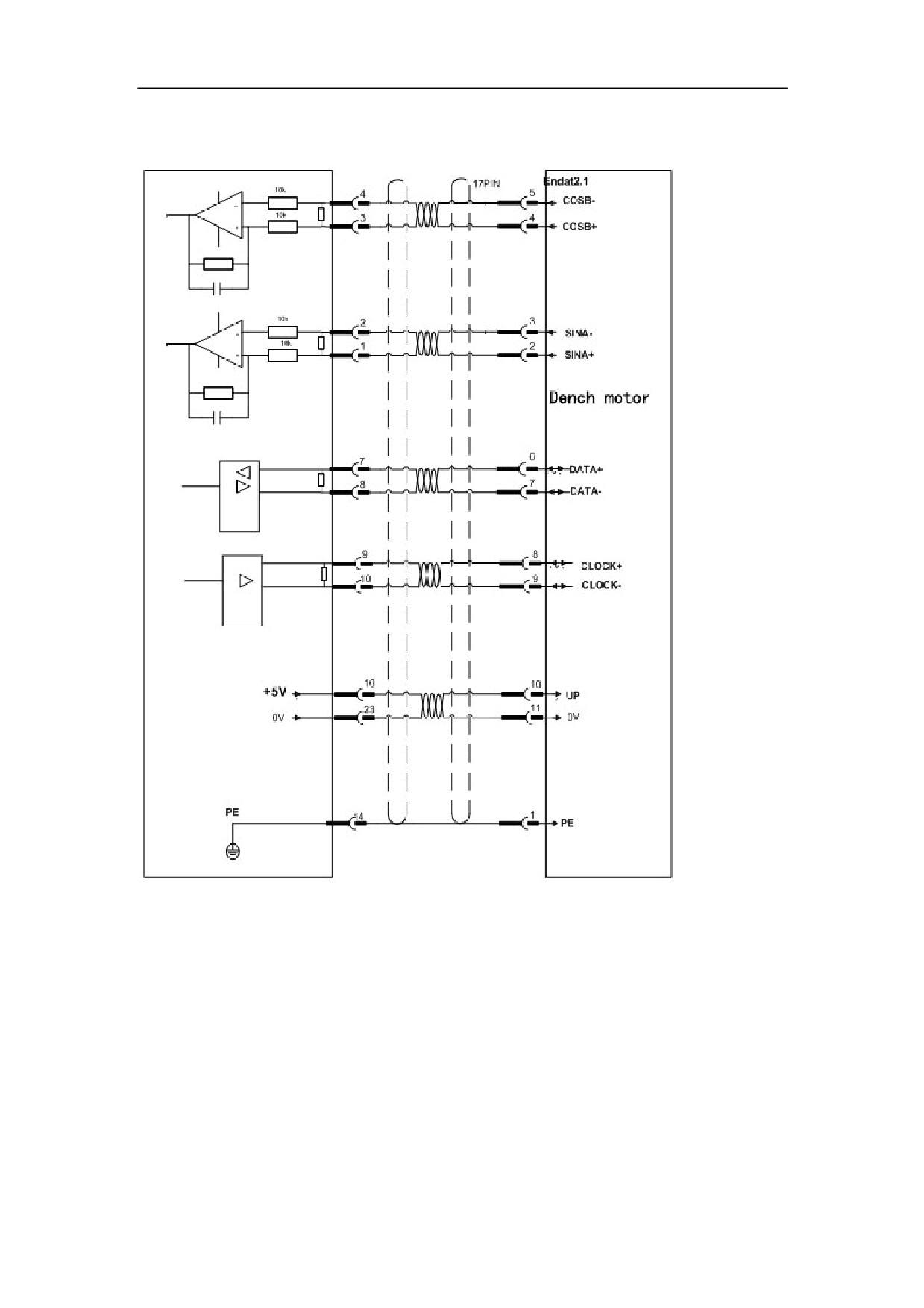
2ǃThe Servo Amplifier connect with ENDAT2.1 agreemen˄EQN1325/1313˅of
Absolute encoder and Dench motor
92
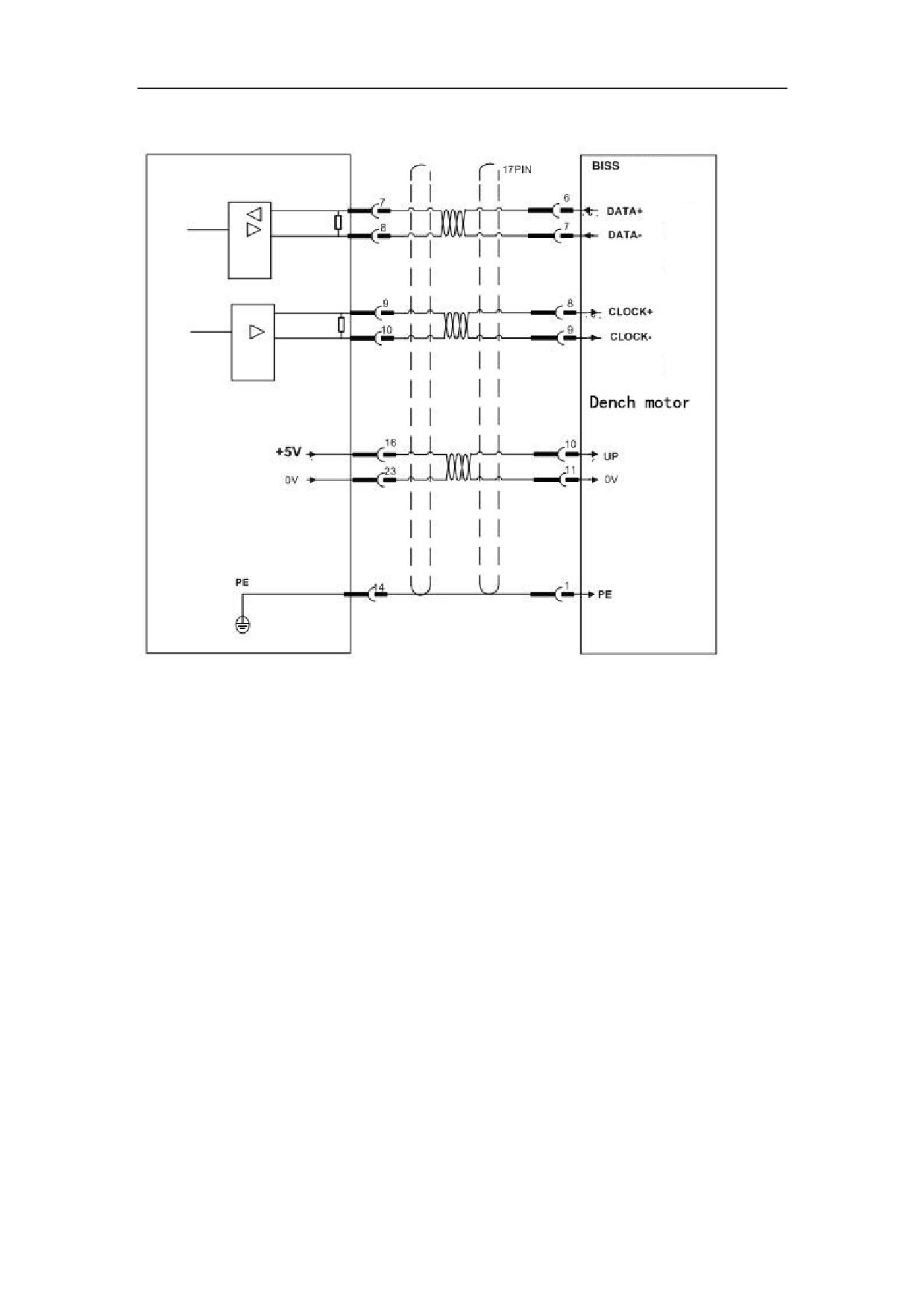
3ǃThe Servo Amplifier connect with BISSagreement of Absolute encoder
93
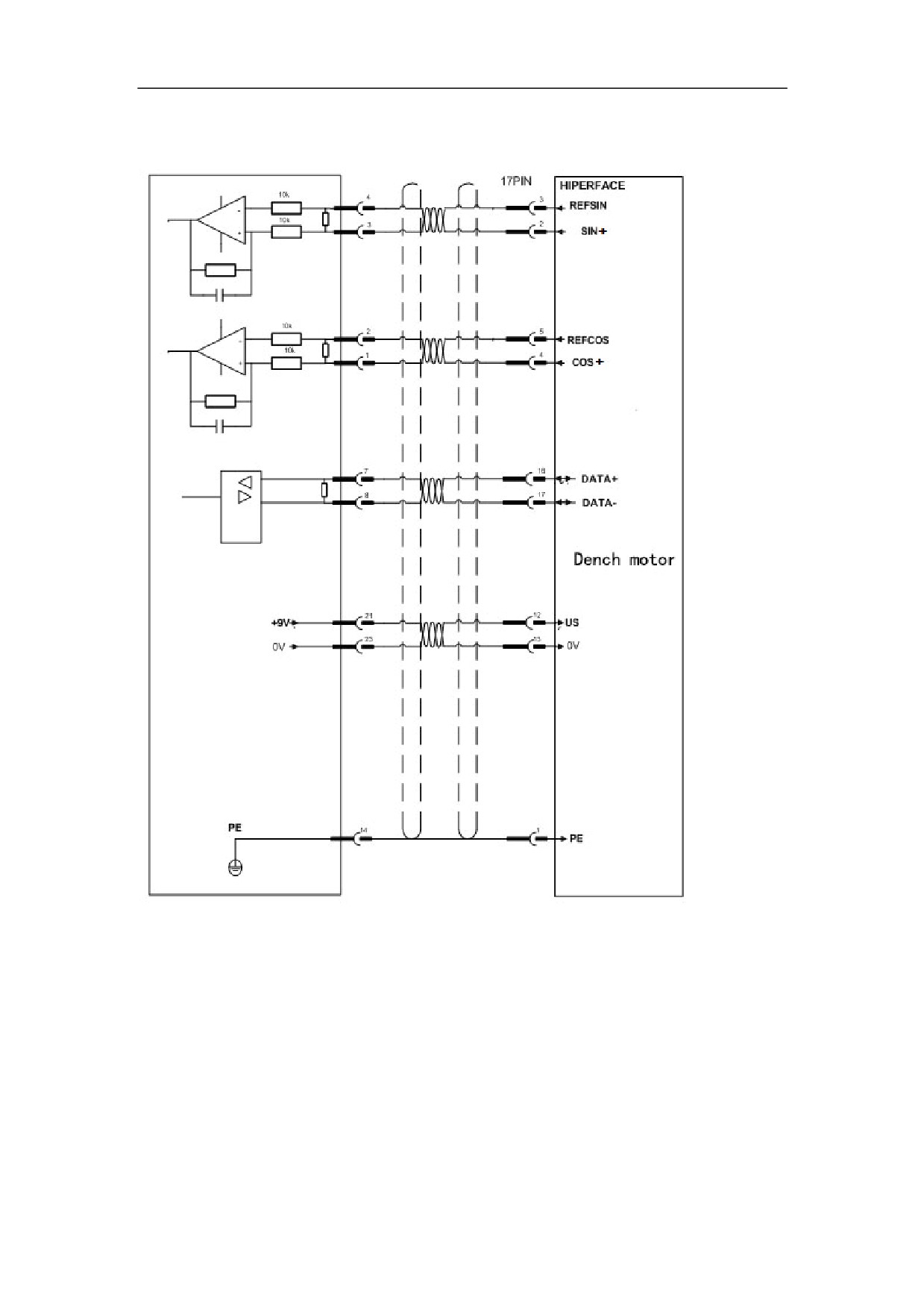
4ǃThe Servo Amplifier connect with Hiper FACE agreement of Absolute
encoder
94
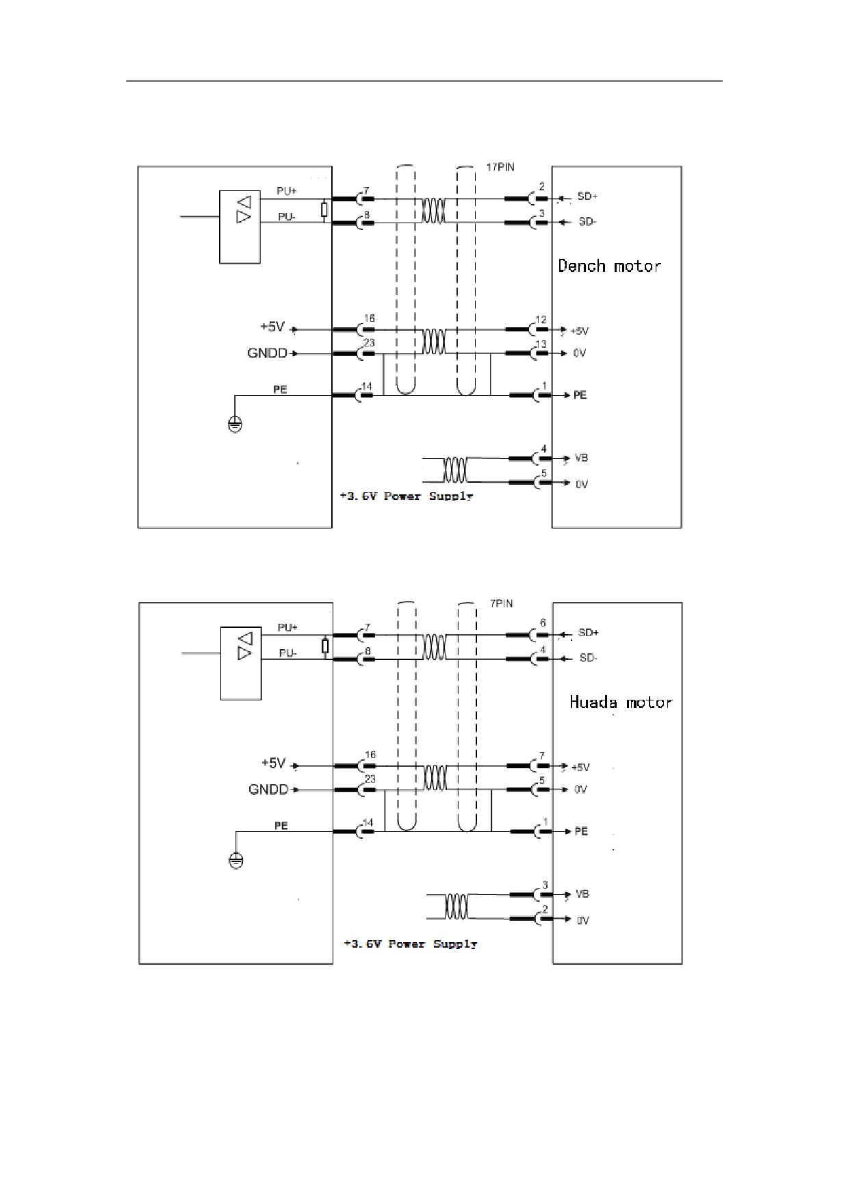
5ǃThe Servo Amplifier connect with Hiper FACE agreement of Absolute
encoder and Dench motor
6ǃThe Servo Amplifier connect with Hiper FACE agreement of Absolute
encoder and Huada motor
95
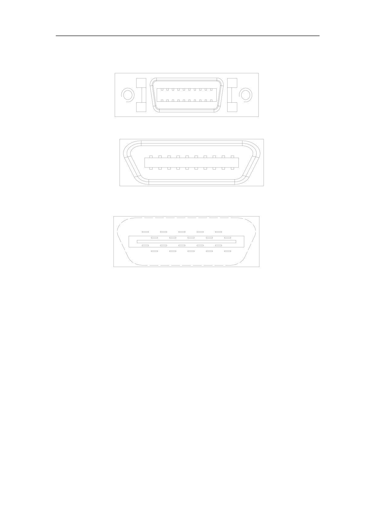
5.5.2.1XS2 ENCODER2 Servo Encoder Input Interface Figure
Figure 5-38 XS2 Servo Encoder Input interface plug
Figure 5-39 XS2 Servo Encoder Input interface plug(looking from the plug)
Figure 5-40 Soldering terminal of XS2 Servo Encode Input interface plug (looking
from the soldering terminal)
96
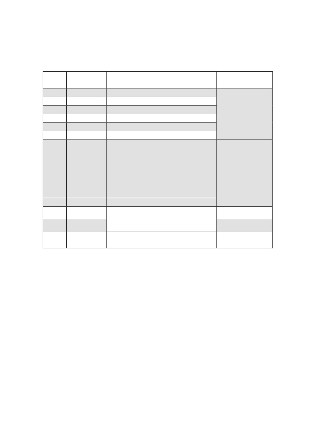
5.5.2.2 XS2 ENCODER2 Servo Encoder Input Interface Function
1ǃDrive servo connect to Incremental photoelectric encoder
Figure 5.11 Signal function of XS2 ENCODER2 connect Incremental photoelectric
encoder
Terminal
Symbol
NO
Function
Symbol
standard
11,12
A+/SINA+
Servo motor encoder feedback A+ input
1,2
A-/SINA-
Servo motor encoder feedback A- input
Line driver
13,14
B+/COSB+
Servo motor encoder feedback B+input
receiver
3,4
B-/COSB-
Servo motor encoder feedback B- input
RS422 standard
15,16
Z+/DATA+
Servo motor encoder feedback Z+input
5,6
Z-/DATA-
Servo motor encoder feedback Z-input
Servo motor encoder +5V power output
terminal
Connect the servo motor
7,8
+5V
optical-electrical encoder with 5 V
DC +5V/150mA
power supply. If the cable is too long,
use multiple wires to form serial
connection.
9,10
GNDD
Servo encoder power ground 0V
19
CLOCK+
Reserved
20
CLOCK-
Shield ground
17,18
PE
It is connected to PE
97
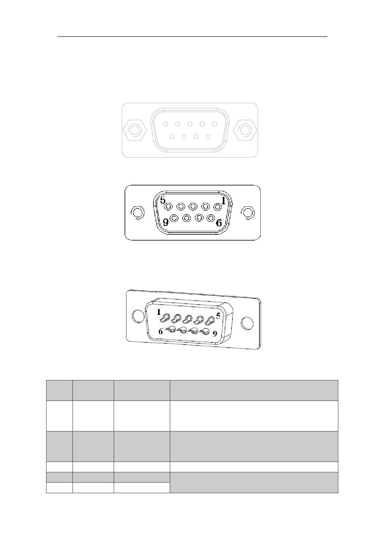
5.6 Connection of the communication signal terminal
5.6.1 XS1 Serial Interface
Figure 5-41 XS1 Serial interface plug
Figure 5-42 XS1 Serial interface plug (looking from the soldering plug)
Figure 5-43 Soldering terminal of XS1 Serial interface plug (looking from the
soldering terminal)
Figur5.12 Function of the communication signal terminal XS1
Terminal
NO.
Signal
Function
Symbol
It is connected to the serial data receiving interface
RS232 Data
2
TX
(RX) of the controller or PC to achieve the serial
transmission
communication.
It is connected to the serial data transmitting
RS232
3
RX
interface (TX) on the controller or PC to achieve
Data reception
the serial communication.
1ˈ5
GNDD
Signal ground
Data signal ground
4
CANL
Reserved
6
CANH
Reserved
98
5.7 Wiring
1ǃPower input terminal XT1, and heavy current power output terminal XT2
Diameter
The terminal diameters ofL3ˈL2ˈL1 on XT1 of HSV-180AD-035ˈ050ˈ
075,100ˈ150.
The terminal diameters of PˈBKˈUˈVˈWˈ PE on XT2 of HSV-180AD-035ˈ
050ˈ075, 100ˈ150.
The terminal diameters ofPˈBKˈL3ˈL2ˈL1,UˈVˈWˈ PEon XT2 of
HSV-180AD-200ˈ300, 450.
The terminal diameters 220Aˈ220B on XT1 of HSV-180AD-200,300,4501.5mm2
(3.0/3.7/5.5/7.5 kw).
Grounding
Grounding wire must be thick. The Servo Amplifier and servo motor must be
connected to PE.
Grounding resistance <4ȍ
Use cold pre-insulated terminals to connect terminals and make sure that the
connection is firm.
Install the non-fuse circuit breaker to promptly cut off the external power when a
Servo Amplifier fault occurs.
It is recommended that shield cable be used to prevent other electrical equipments
from interference.
2ǃControl signal XS4, feedback signal XS3 for servo motor optic-electrical
encoder, servo encoder feedback signal XS2, and XS1 Serial Interface
Diameter
Shield cable is used (stranded shield cable is the best choice), and the cross-sectional
area is greater than or equal to 0.12mm2 (AWG24-26). The shielded layer must be
connected to the metal shell of the connection plug.
Cable length
The cable must be short. The length of the control signal cable XS4 is not greater than
10 meters, and the length of the feedback signal cable XS2, XS3 is no more than 40
meters.
Wiring
The wiring must be away from the electric power circuit to prevent interference.
Install surge absorbers with inductive components (coils) of related circuits.
Freewheeling diodes are antiparallel connected to the DC coils, and RC absorbed
circuits are paralleling connected to the AC coils.
3ǃI/O input/output terminal XS5
˄1˅Diameter: use ordinary cable or shielded cable, wire cross-sectional area
1.5mm2.
˄2˅Cable length: cable length as short as possible and not more than 10 meters.
99