Series HSV-180AD AC Servo Amplifier. User's Manual (V1.00 2012.4) - page 7
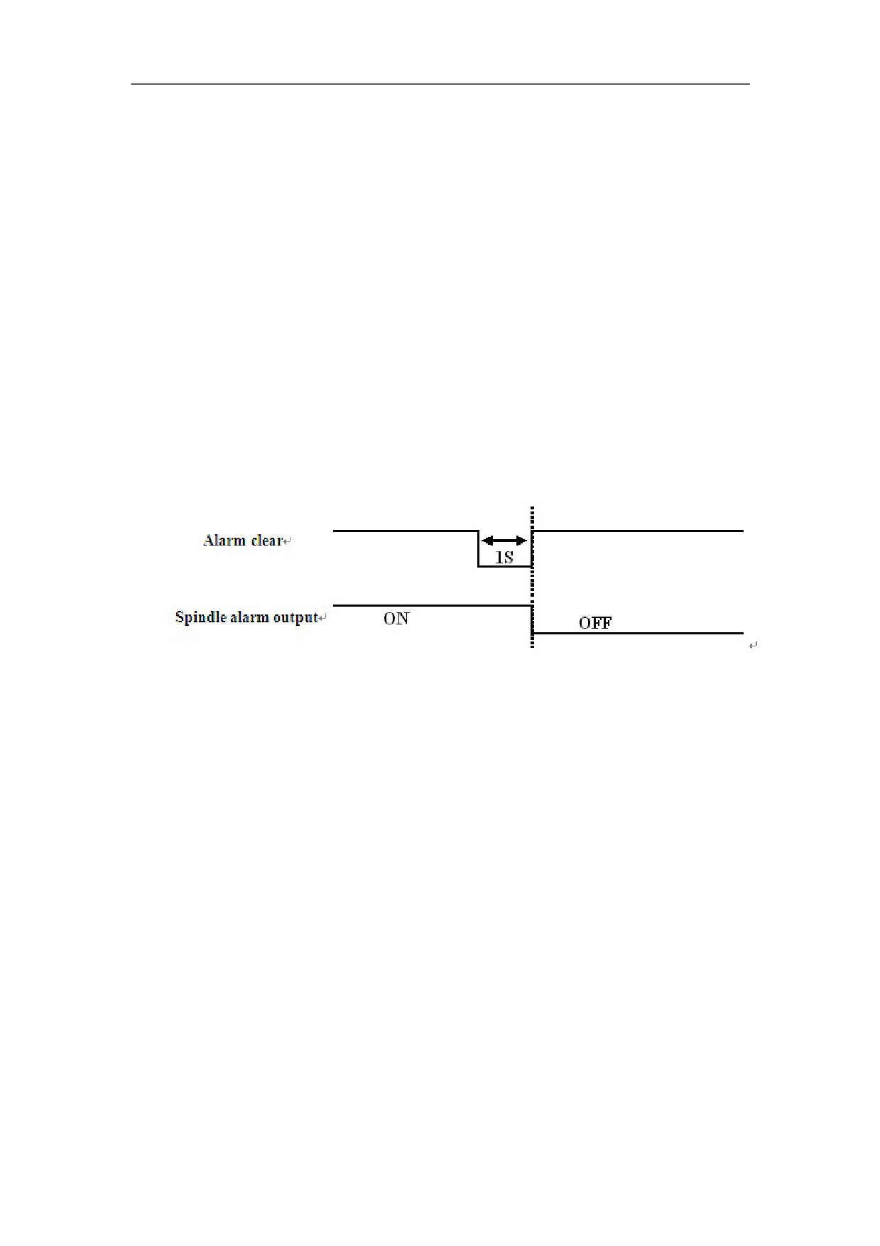
z Do not turns off the power, after the fault source is cleared, and enter the
auxiliary mode to reset the internal alarm to clear the alarm. After the alarm is
reset, the red alarm light is off (indicating the alarm is cleared), the servo alarm
(ALM) output is disconnected and the failure chain relay normally-open contact
on the input/output terminal XS5 is connected.
z Do not turns off the power, after the fault source is cleared, reset the external
alarm to clear the alarm via the alarm clear input signal (ALM_RST), see Figure
8-4. After the alarm is reset, the red alarm light is off (indicates the alarm is
cleared), the servo alarm (ALM) output is disconnected and the failure chain
relay normally-open contact on the input/output terminal XS5 is connected.
Figure 8-6 Sequential diagram for external alarm clear
8.2 Trial Operation
Before operating any modes as follows, you must check whether the motor parameter
setting of Servo Amplifier and phase sequence of motor power line is right. Steps as
follows:
1ǃFor HSV-180AD-150 Servo Amplifier and below, disconnect motor coding cable
and motor power line, connect the main circuit power (three-phase AC380V) of the
Servo Amplifier.
2ǃ For HSV-180AD-200 Servo Amplifier and above, disconnect motor coding cable
and motor power line, connect the main circuit power (single-phase AC220V) of the
Servo Amplifier.
3ǃModify control parameters and movement parameters:
Setting STA—0 to 0, STA—6 to 1
According to the Servo Amplifier and type of motor encoder, setting follow
parameters: PA--34, PA--25ˈPA--26 and PA--43.
4ǃChanging PA--34 to 1230 after completing setting,, enter auxiliary parameter
setting mode to save parameter, and turn off at last.
5ǃConnect encoder and power line of motor:
150
For HSV-180AD-150 and below specifications˖ only need to connect the
three-phase AC380V of strong electricDŽ
For HSV-180AD-200 and above specifications˖Firstly connect single-phase
AC220V of control powerˈand then connect the three-phase AC380V of strong
electricDŽ
6ǃAfter the Servo Amplifier digital display, select the auxiliary mode "TST-MD"
(open-loop control mode), press S to enter, when display "FINISH", the green Servo
Amplifier enable lights, look up the DP- PFL the actual status, if the value is
increasing without decimal point, it indicates that the phase sequence of motor power
line UVW is right. Otherwise, the motor power lines indicate the sequence is wrong,
switch off the Servo Amplifier power , swap the motor power line V, W phase
sequence can be.
Note:Operating steps above, the motor shaft must be no load.
8.2.1 JOG Running Mode
1ǃFor wiring, see Figure 5.8 in Chapter 5
2ǃ For HSV-180AD-150 Servo Amplifier and below ,disconnect motor coding
cable and motor power line, connect the main circuit power (three-phase AC380V) of
the Servo Amplifier.
For HSV-180AD-200 Servo Amplifier and above, disconnect motor coding cable
and motor power line, connect the main circuit power (single-phase AC220V) of the
Servo Amplifier.
3ǃ Modify control parameters and movement parameters:
Setting STA—0 to 0˗Setting STA—6to 1˗
According to the type of Servo Amplifier, setting follow parameters STB--1˄IM˖
0ˈPM:1˅˗
Setting PA--34to 2003, PA—25 and PA—43
4ǃSave the parameter to EEPROM after setting PA--34to 1230. Turn off the power,
wait for 30seconds
5ǃConnect encoder and power line of motor:
For HSV-180AD-150 and below specifications˖only need to connect the three-phase
AC380V of strong electricDŽ
For HSV-180AD-200 and above specifications˖Firstly connect single-phase
AC220V of control powerˈand then connect the three-phase AC380V of strong
electricDŽ
6ǃConnect the main circuit power (three-phase AC380V) of the Servo Amplifier. If
there are no alarms or abnormal situation, the green enable lamp (EN) is light, which
indicates the Servo Amplifier is working properly. The motor is activated and in the
zero speed state.
7ǃIn the auxiliary mode, select the JOG mode, and JOG-- is displayed through the
digital cube. Press
S to enter into the JOG mode. RUN-- is displayed through the
digital cube. Press and hold
Ĺ
, the servo motor runs at the JOG speed. Release
Ĺ
, and
then the motor stops and enters the zero-speed state. Press and hold
Ļ
, the motor runs
151
at the JOG speed in the opposite direction. Release
Ļ
, and then the motor stops and
enters the zero-speed state.
8.2.2 Internal Speed Running Mode
1ǃFor wiring, refer to Figure 5.8 in Chapter 5
2ǃFor HSV-180AD-150 Servo Amplifier and below ,disconnect motor coding cable
and motor power line, connect the main circuit power (three-phase AC380V) of the
Servo Amplifier.
For HSV-180AD-200 Servo Amplifier and above ,disconnect motor coding cable
and motor power line, connect the main circuit power (single-phase AC220V) of the
Servo Amplifier.
3ǃ Modify control parameters and movement parameters:
Setting STA-0to 0˗STA-6to 1
Setting PA—34to 2003˗
Setting PA—23 to 3˗Servo Amplifier to work in the internal speed mode
SettingPA—25,26,43˗
4ǃSave the parameter to EEPROM after setting PA--34to 1230. Turn off the power,
wait for 30seconds
5ǃ Connect encoder and power line of motor:
For HSV-180AD-150and below specifications˖ only need to connect the
three-phase AC380V of strong electricDŽ
For HSV-180AD-200 and above specifications˖Firstly connect single-phase
AC220V of control powerˈand then connect the three-phase AC380V of strong
electric6.
6ǃIf there are no alarms or abnormal situation, the green enable lamp (EN) is light,
which indicates the Servo Amplifier is operating normal. The motor is activated and
in the zero speed state.
7ǃSet the movement parameter PA-20 (internal speed). Press
S to confirm, and then
the motor will run at the specified speed.
8.2.3 External Speed Running Mode (Analog interface)
1ǃFor wiring, see Figure 5.8.2 in Chapter 5.
2ǃ For HSV-180AD-150 Servo Amplifier and below ,disconnect motor cable and
motor power line, connect the main circuit power (three-phase AC380V) of the Servo
Amplifier.
For HSV-180AD-200 Servo Amplifier and above, disconnect motor coding cable and
motor power line, connect the main circuit power (single-phase AC220V) of the
Servo Amplifier.
3ǃModify control parameters and movement parameters:
Setting STA-0to 0˗STA-6to0˗PA—34to2003
Setting PA—25, PA—26,PA—43
Setting PA—23 to 1, Servo Amplifier in the external speed control mode
According to the demand , setting the speed parameter PA—7 and PA--8
152
4ǃSave the parameter settings to EEPROM after setting PA--34to 1230. Turn off the
power, wait for 30secondsDŽ
5ǃ Connect encoder and power line of motor:
For HSV-180AD-150 and below specifications˖ only need to connect the
three-phase AC380V of strong electricDŽ
For HSV-180AD-200 and above specifications˖Firstly connect single-phase
AC220V of control powerˈand then connect the three-phase AC380V of strong
electricDŽ
6ǃ Verify no alarm or abnormal condition is reported. The green enable lamp (EN)
is on, which indicates the Servo Amplifier is working properly. The motor is activated
and in the zero speed state.
7ǃUse PC outputs forward or reverse control signal to the third pin (FWD) and the
forth pin (REW) and outputs analog signal to the 27, 28, 12, 13 pin (GNDAM, AN+,
AN-) on the command input/output interface XS4. The motor rotate forward or
reverse.
8.2.4 Torque Running Mode (Analog interface)
1ǃFor wiring, see Figure 5.8.2 in Chapter 5.
2ǃFor HSV-180AD-150 Servo Amplifier and below ,disconnect motor coding
cable and motor power line, connect the main circuit power (three-phase AC380V) of
the Servo Amplifier.
For HSV-180AD-200 Servo Amplifier and above ,disconnect motor coding cable and
motor power line, connect the main circuit power (single-phase AC220V) of the
Servo Amplifier.
3ǃModify control parameters and movement parameters:
Setting STA-0to 0˗STA-6to0˗PA—34to2003
Setting PA—25, PA—26,PA—43
Setting PA—23 to 2, Servo Amplifier in the external speed control mode
According to the demand , setting parameter PA—9 and PA--10
4ǃSave the parameter to EEPROM after setting PA--34to 1230. Turn off the power,
wait for 30seconds
5ǃConnect encoder and power line of motor:
For HSV-180AD-150 and below specifications˖ only need to connect the
three-phase AC380V of strong electricDŽ
For HSV-180AD-200 and above specifications˖Firstly connect single-phase
AC220V of control powerˈand then connect the three-phase AC380V of strong
electricDŽ
6ǃIf there are no alarms or abnormal situation, the green enable light (EN) is on
which indicates the Servo Amplifier working properly. The motor is activated and in
the zero speed state.
7ǃPC sends pulse command to the 27ǃ28ǃ12ǃ13˄GNDAMǃAN+ǃAN-˅ pins
on the command input/output interface XS4. The motor runs according to the
command.
153
8.2.5 Position Running Mode (Impulse interface)
1ǃFor wiring, see Figure 5.8.1 in Chapter 5.
2ǃFor HSV-180AD-150 Servo Amplifier and below ,disconnect motor coding cable
and motor power line, connect the main circuit power (three-phase AC380V) of the
Servo Amplifier.
For HSV-180AD-200 Servo Amplifier and a above, disconnect motor coding cable
and motor power line, connect the main circuit power (single-phase AC220V) of the
Servo Amplifier.
3ǃModify control parameters and movement parameters:
Setting STA-0to 0˗STA-6to0˗PA—34to2003
Setting PA—25, PA—26,PA—43
Setting PA—23 to 0
According to the demand , setting parameter PA—22
4ǃSave the parameter to EEPROM after setting PA—41to 1230. Turn off the power,
wait for 30seconds
5ǃConnect encoder and power line of motor:
For HSV-180AD-150 and below specifications˖ only need to connect the
three-phase AC380V of strong electricDŽ
For HSV-180AD-200 and above specifications˖Firstly connect single-phase
AC220V of control powerˈand then connect the three-phase AC380V of strong
electricDŽ
6ǃIf there are no alarms or abnormal situation, the green enable light (EN) is on,
which indicates the Servo Amplifier is working properly. The motor is activated and
in the zero speed state.
7、The PC sends pulse command to the 14,15,16,17 pins on the command
input/output interface XS4. The motor runs according to the command.
8.2.6 Full closed-loop
1ǃFor wiring, see Figure 5.8.3Standard wiring diagram in Chapter 5.
2ǃFor HSV-180AD-150 Servo Amplifier and below , disconnect motor coding cable
and motor power line, connect the main circuit power (three-phase AC380V) of the
Servo Amplifier.
For HSV-180AD-200 Servo Amplifier and above, disconnect motor coding cable and
motor power line, connect the main circuit power (single-phase AC220V) of the
Servo Amplifier.
3ǃModify control parameters and movement parameters˖
Setting STA-0to 0˗STA-6to 0˗
Setting STB-14 to 0,select forbid full closed-loop function
Setting PA—34 to 2003
Setting PA—25, PA—26, PA—43, PA--22
Setting PA—23 to 0
4ǃSave the parameter to EEPROM after setting PA—34to 1230. Turn off the power,
wait for 30seconds
154
5ǃConnect encoder of motor:
For HSV-180AD-150 and below specifications˖ connect the three-phase AC380V
of strong electricDŽ
For HSV-180AD-200 and above specifications˖ connect single-phase AC220V of
control powerDŽ
6ǃManually rotate the servo motorˈobserve the value of DP-PFL, DP-PFM,
confirm the count direction of feedback pulse when reversing.
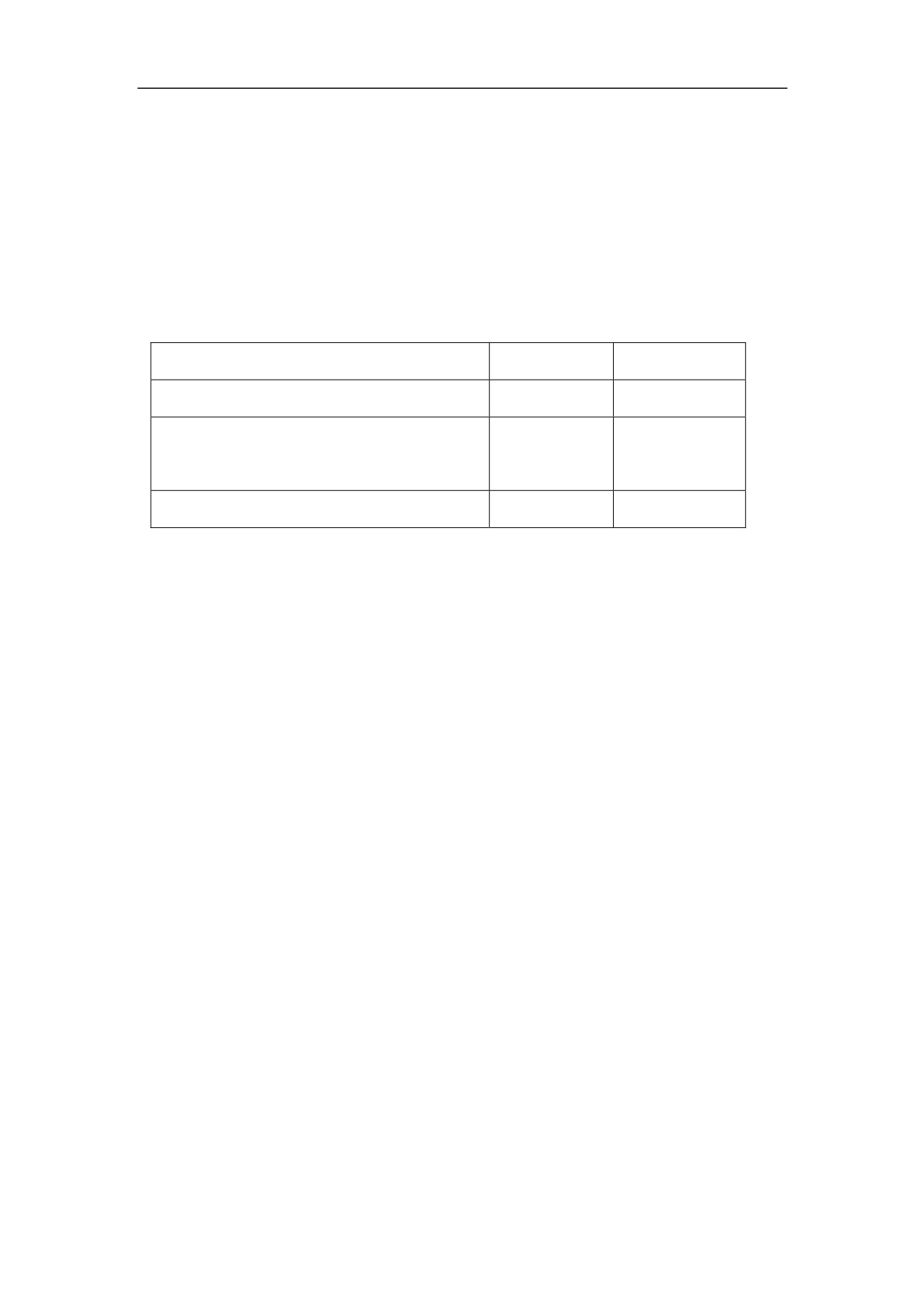
7ǃSetting STB-14 to 1, select closed loop function
Setting STB-12ǃSTB-13, select the second position encoder type
The second position encoder type
STB-13
STB-12
Square Incremental Encoder ˄TTL˅
0
0
ENDAT2.1/2.2 Agreement absolute
1
0
encoder
Cosine encoder˄1Vpp Analog signals˅
1
1
8ǃSave the parameter to EEPROM after setting PA—34to 1230. Turn off the power,
wait for 30seconds
9ǃConnect the second position encoder:
For HSV-180AD-150 and below specifications˖ connect the three-phase AC380V
of strong electricDŽ
For HSV-180AD-200 and above specifications˖ connect single-phase AC220V of
control power
10ǃManually rotate the servo motorˈobserve the value of DP-PFL, DP-PFM,
confirm the count direction of feedback pulse when reversing is consist with the
direction as steps 6
If the count direction is not consist with the direction as steps 6,set PA-10 to
512,and invert servo encoder feedback pulse.
11ǃSave the parameter to EEPROM after setting PA—34to 1230. Turn off the
power, wait for 30seconds
12ǃConnect power line of motor:
For HSV-180AD-150 and below specifications˖ connect the three-phase AC380V
of strong electricDŽ
For HSV-180AD-200 and above specifications˖Firstly connect single-phase
AC220V of control powerˈand then connect the three-phase AC380V of strong
electricDŽ
13ǃAdjust parameters PA-17, PA-21 to be smaller, test by JOG point dynamic. If
tests are normal, turn off the power, and wait 30 seconds.
14ǃConnect command line of motor:
For HSV-180AD-150 and below specifications˖ connect the three-phase AC380V
of strong electricDŽ
155
For HSV-180AD-200 and above specifications˖Firstly connect single-phase
AC220V of control powerˈand then connect the three-phase AC380V of strong
electric.
15 ǃIf there are no alarms or abnormal situation, the green enable light (EN) is on,
which indicates the Servo Amplifier is working properly. The motor is activated and
in the zero speed state.
16、.Operate PC outputs pulse command to the 14, 15, 16, 17 pin (CP+ǃCP-ǃ
DIR+ǃDIR-) on the XS4 interface. The motor run according to the command.
8.3 Running Modification
Note
z Wrong parameter setting may cause equipment failure or
accidents. Make sure the parameter settings are correct before
starting the Servo Amplifier.
It is recommended that the overload commissioning be performed
after the non-load commissioning.
8.3.1Basic Gain
A: Speed Control
z Speed proportional gain: specified by the movement parameter PA-2. Gain and
rigidity will be enhanced as the parameter value increases. The value is
determined by the actual Servo Amplifier system type and the load. It is
recommended that the value be larger if no oscillation exists. In general, the value
of speed proportional gain increases as the loading inertia increases.
z Speed integration time constant: specified by the movement parameter PA-3.
Integration speeds up as the value decreases. The response speed increases as the
parameter value decrease, but oscillation may occur. It is recommended that the
value be smaller if no oscillation exists. A big parameter value may leads to great
changes in speed when the load changes. In general, the value increases as the
load inertia increases.
B: Position control
z Set an appropriate value for speed proportional gain and speed integration time
constant based on the information in Speed control.
156
z Position forward feedback gain: It is specified by the movement parameter PA-1.
The system response enhanced as the value increases, but instability or oscillation
may occur. It is recommended that the value be set to 0.
z Position proportional gain: It is specified by the movement parameter PA-0.
Gain and rigidity will be enhanced as the parameter value increases, but the
position hysteresis decreases under the condition of the same pulse frequency.
The value is determined by the actual Servo Amplifier system type and the load.
It is recommended that a big value be set. The position command tracking feature
is enhanced but the lag error decreases as the parameter value increases. However,
oscillation easily occurs after the orientation is complete.
z If high position command tracking feature is required, set the parameter to a
bigger value. However, it may cause overshoot or oscillations.
For the Position proportional gain parameter setting, see the following table.
Recommended values for Position proportional gain
Rigidity
Value
Low
500̚1000
Middle
1000̚2000
High
2000̚3000
8.3.2Electrical Gear Setting
In the position control mode, by changing the position command pulse frequency
molecular (movement parameter PA-13) and position command pulse frequency
denominator (movement parameter of PA-14), users can easily match with the
pulse controller to achieve position control resolution as required.
The position resolution (a pulse travel̲l) is determined by the servo motor travel
per turn (̲S) and encoder feedback pulses per revolution Pt. The formula is as
follows:
S
l
Pt
In the formula,
̲l: Indicates a pulse travel (mm)
̲S: Indicates servo motor travel per turn (mm/turn)
Pt: indicates encoder feedback pulse per revolution (pulse/rev.)
157
Fourfold frequency circuit is provided for the Servo Amplifier: Pt = 4 × C.
C indicates the number of encoder lines per revolution. In this system C is 2500
lines/turn (specified by encoder resolution and movement parameter PA-25), then
Pt = 1000 pulses/rev.
Multiply command pulse with the electronic gear ratio G to get the position control
pulse. The formula for one command pulse travel ̲l* is as follows:
S
l
G
Pt
In the formula, G = position command pulse frequency molecular/position
command pulse frequency denominator
8.3.3Start and Stop Adjustment
The Servo Amplifier start and stop feature, namely, acceleration and deceleration
time, is determined by the over-load inertia and start and stop frequency, and
limited by the Servo Amplifier and servo motor performance. Frequent start and
stop, short acceleration and deceleration time, large load inertia will cause over
heat to the Servo Amplifier and motor and over voltage to the main circuit. You
need to adjust them as required.
a. Overload inertia and start and stop frequency adjustment
The adjustment is required when the start and stop frequency is too high. Check
whether the frequency is in the frequency range. The frequency range varies with
different motor types, capacities, load inertias, and motor speeds. If the overload
inertia is M times of the motor inertia, the start and stop frequency and
recommended deceleration time (movement parameter PA-6) is as in the
following table:
Load inertia ratio and allowed start and stop frequency
Load Inertia
Allowed Start-Stop Frequency
Times
m 3
>100 times/mins: acceleration and deceleration time is
60 ms or less
m 5
60 to 100 times/mins: acceleration and deceleration
time is 150 ms or less
158
m > 5
< 60 times/mines: acceleration and deceleration time is
150 ms or more
b. Impact of the servo motor
Different type of servo motor allows different overload conditions, running
times, loading rate, and environment temperature. See related manual and
adjust the settings as required to prevent overheat or short service life.
c. Adjustment method
Generally, the overload inertia must be less than 5 times of the motor rotor
inertia. The large overload inertia may cause overvoltage during deceleration
or abnormal braking. Use the following methods to adjust it:
z Increasing the acceleration and deceleration time (movement parameter
PA-6 and PA-38)
You can set the parameter to a bigger value and then gradually reduce it to
the appropriate value.
z Reducing the maximum output torque value (movement parameter PA-5)
to reduce the current limit value
z Reducing the maximum speed limit of the servo motor (movement
parameter PA-17)
z Installing external braking device
z Changing the servo motor to one with larger power and inertia motor (the
servo motor must match with the Servo Amplifier)
159

9 Fault Trouble shooting
Caution
z Maintenance personnel must have related knowledge and abilities.
z Do not touch the Servo Amplifier or motor within five minutes after
power-off to prevent electric shock or burns.
z If a Servo Amplifier alarm is reported, do not use the Servo Amplifier
only after the alarm is cleared based on the alarm code.
z Before the alarm reset, make sure that the EN signal is ineffective to
prevent accidents caused by a sudden start.
9.1 Protection and Fault Identification
1.
Series HSV-180AD Servo Amplifier provides 30 different protection
functions and fault identification. If one protection function is activated,
alarm information can be displayed through the digital tube on the Servo
Amplifier panel, the servo alarm output (ALM) is connected, and the failure
chain relay normally-open contact on the input/output terminal XS5 is
disconnected.
2.
It is required to connect the alarm output (ALM)or XS5 terminal to the PC.
When the protection function of the Servo Amplifier is activated, the PC can
promptly take emergency measures.
3.
After the fault source is cleared, you can turn off three-phase main power ,
and then the repower the Servo Amplifier to clear the alarm, or enter the
auxiliary mode to reset the internal alarm to clear the alarm, or reset the
external alarm to clear the alarm via the alarm clear input signal
(ALM_RST).
4.
The protection function with "*" cannot be cleared by resetting the external
or internal alarm. It can only be cleared by cutting off the power, and then
repower the Servo Amplifier after the fault source is cleared.
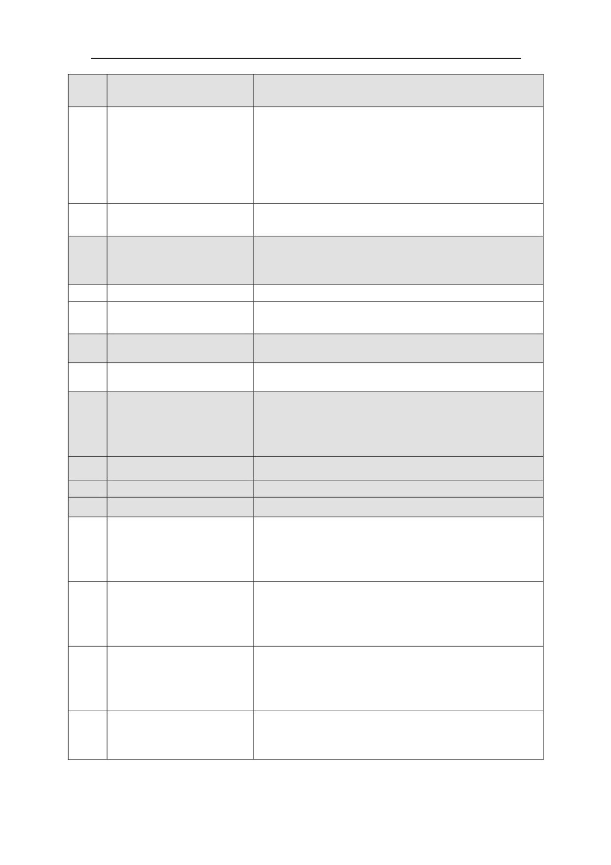
Table 9.1 Alarm information:
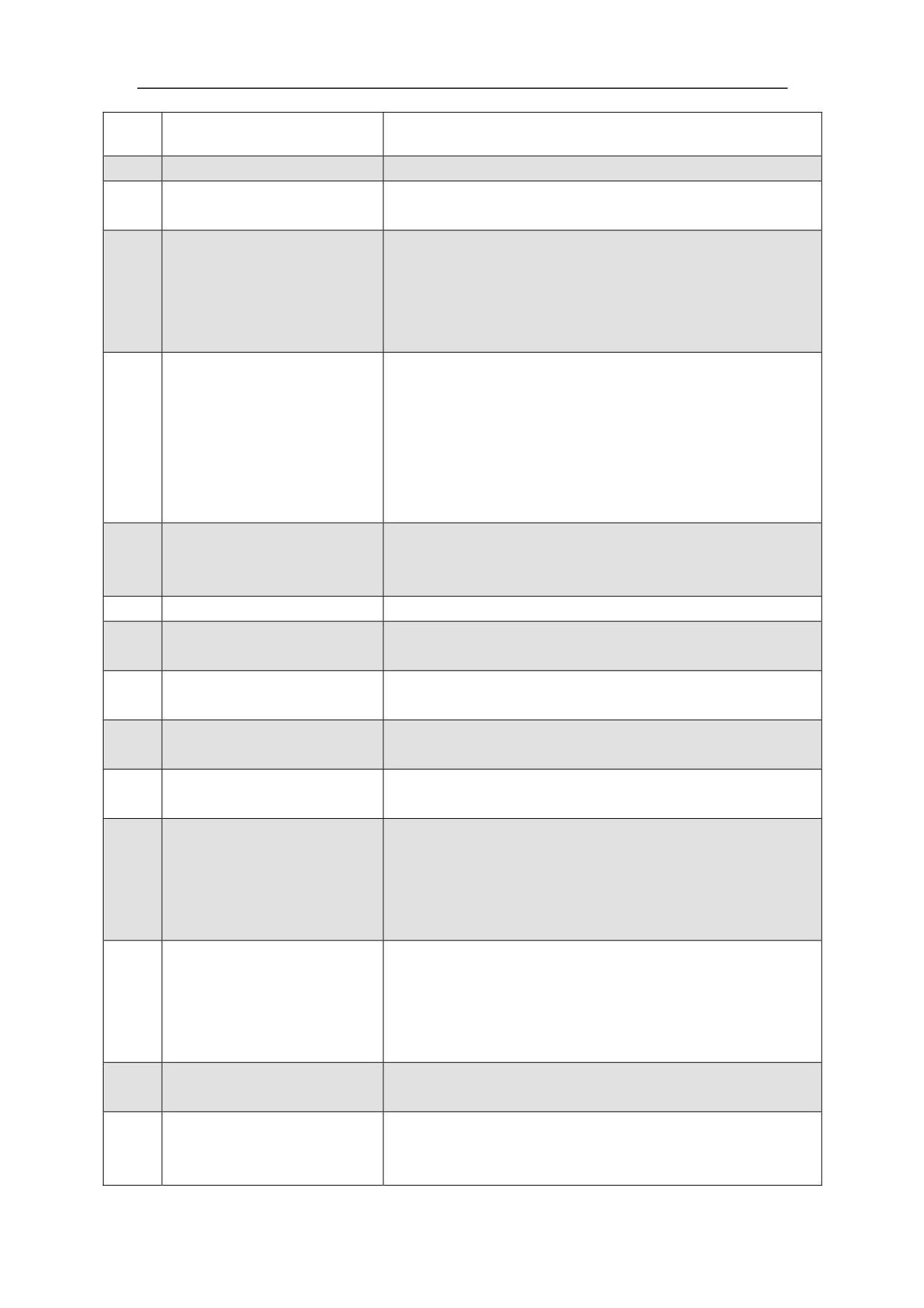
No.
Alarm Type
Description
0
Normal
No alarming
Whether the three-phase main voltage is c˛
1
Under-voltage supply
Whether the three-phase main voltage is too low˛
Whether the built-in braking resistor of Servo
Amplifier is intact?
2
Over-voltage supply
Whether external braking resistor specifications and
wiring is correct?
Whether the circuit power supply voltage is too high˛
Whether the cooling of Servo Amplifier is normal˛
Whether the system is overload˛
Whether parameter settings are appropriate˛
3
IPM failureƹ
Whether connection of motor power line is correct and
reliable ?
Whether connection of Shielded cable is complete, and
reliable?
Whether external braking resistor is correct?
4
Brake failureƹ
Whether external braking resistor specifications and
wiring is correct?
5
Reserved
Temperature of motor is too high
6
Motor overheat
STA-12 is set to 1to shield alarm
The encoder data signal
Whether encoder cable is connected and reliable˛
7
error
Whether the encoder cable is too long?
Whether encoder cable is connected˛
8
The type of encoder error
Whether setting of P-25 is correct ˛
Whether the phase sequence of motor power line is
9
system software overheat
correct˛
Whether setting of PA--10ǃPA--18ǃPA--19 is
correct˛
10
Over currentƹ
Whether setting of PA--26 is correct˛
Whether the Servo Amplifier is overload˛
Whether setting of PA--17 is correct˛
Whether the r feedback signal of encode is correct˛
11
Motor over speed
If the system work in full closed loop mode: whether
direction of full closed-loop feedback pulse is consistent
with the direction of semi-closed loop feedback pulse˛
Overlarge tracking
Whether the phase sequence of motor is correct˛
12
deviation
Whether setting of P-12 is correct˛
Whether setting of PA--18ǃPA--19 is correct˛
Motor overload for a long
13
Whether the phase sequence of motor is correct˛
time
161
Control parameters read
Resave parameters
14
faultƹ
Whether PA17 parameter set is reasonable
after given an instruction frequency more than it?
Whether PA23 parameter set is reasonable?
15
Instruction Over clocking
Whether the system of electronic gear ratio, the encoder
type or operating mode is correct?
Whether PB42andPB4 is reasonable?
Control board hardware
DSP and FPGA communication failure
16
failureƹ
Resave parameters
Temperature of the Servo Amplifier exceeds the set
17
Servo Amplifier overheat
value˄100ć˅
STB--4 is set to 1to shield alarm
18
Reserved
19
ADconversion data communications failure or current
ADConversion failureƹ
sensor failure
Reverse over travel input switch input is active
20
Reverse over travel fault
Forward over travel input switch input is active
21
Forward over travel fault
Inertia recognition errors
Self-tuning error
Check the operation parameters especially parameters
22
recognition system
such asPA18
Whether system inertia and motor is reasonable?
23
Reserved
24
Reserved
25
Reserved
Absolute encoder communication failure
Motor encoder signals
Whether the connection of encoder cable is correct˛
26
Communication fault
Whether parameter PA - 25 is consistent with the motor
encoder˛
Whether connections of closed loop encoder are
Closed loop cosine
proper ?
27
encoder signal distortion
Whether settings of closed loop encoder type are
correct?
Closed loop encoder
Whether connections of closed loop encoder are
signals
proper ?
28
Communication
Whether settings of closed loop encoder type are
breakdown
correct?
Servo Amplifier and
Whether setting of PA--43 is correct˛
29
motor model code
matching faultƹ
162
Version history of HSV-180AD Servo Amplifier:
1 Series HSV-180AD Servo Amplifier User's Manual V1.00 2012.4
a. Applicable to HSV-180AD-035ˈ050ˈ075ˈ100ˈ150ˈ200ˈ300ˈ450 Servo
Amplifier
b. Software version V 1.13