Century Star Turning CNC System. Programming Guide (V3.5 April, 2015) - page 5
+X
△z
r
B
●
A
1
△d
r
△d
A’ ●
△x/2
+Z
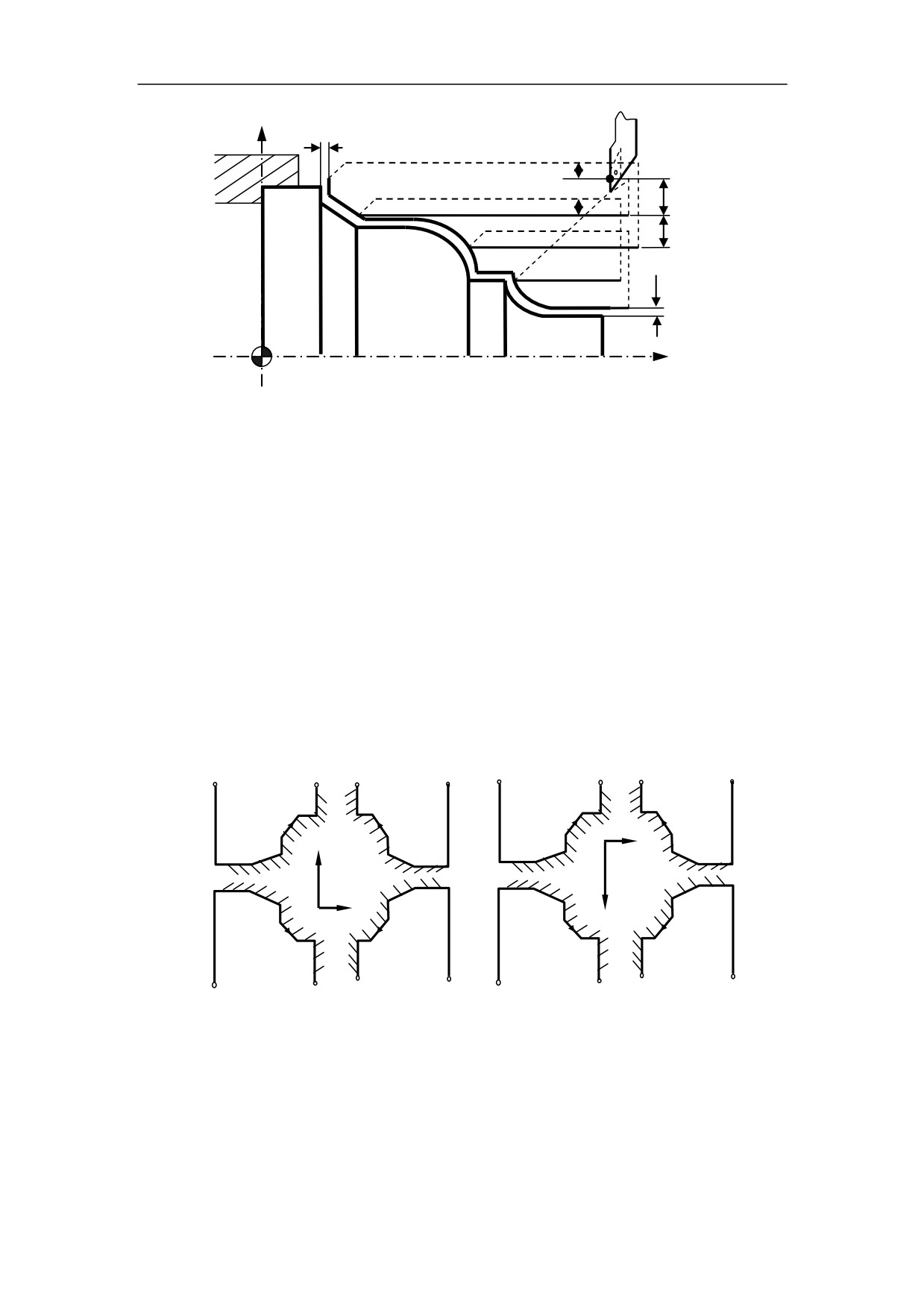
Figure 9.16 Stock Removal in Turning without Groove (G71)
Function
This command can do a stock removal in facing without groove. The machining path
is A→A'→B
Note
1) G00 or G01 must be used in the finishing program - between P(ns) and Q(nf).
Otherwise, there is an alarm message.
2) G71 cannot be used in MDI mode.
3) G98 and G99 cannot used in the finishing program - between P(ns) and
Q(nf).
4) The direction of △ x and △ z is shown in the following figure.
A
B
B
A
A
B B
A
X(-) Z(-)
X(+) Z(+)
X(-)Z(+)
X(+) Z(-)
+Z
+X
A′
A′
A′
A′
A′
A′
A
′
A
′
+Z
+X
X(-) Z(-)
X(-)Z(+)
X(+) Z(-)
X(+) Z(+)
A
A
A
B
B
A
B
B
Figure 9.17 Direction of the finishing allowance in G71
116
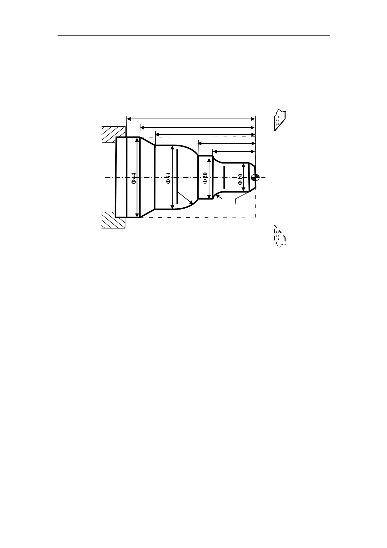
Example 1
The initial point A is (46, 3). The depth of cut is 1.5mm (radius designation). The
retraction amount is 1mm. The finishing allowance in the X direction is 0.6mm, and
the finishing allowance in the Z direction is 0.1mm. The dashed line stands for the
original part.
82
62
52
35
25
R7
R5
2×45°
Figure 9.18 Outer Diameter Removal without Groove - Example
%3325
T0101
N1 G00 X80 Z80
N2 M03 S400
N3 G01 X46 Z3 F100
N4 G71U1.5R1P5Q13X0.6 Z0.1
N5 G00 X0
N6 G01 X10 Z-2
N7 Z-20
N8 G02 U10 W-5 R5
N9 G01 W-10
N10 G03 U14 W-7 R7
N11 G01 Z-52
N12 U10 W-10
N13 W-20
N14 X50
N15 G00 X80 Z80
N16 M05
N17 M30
117
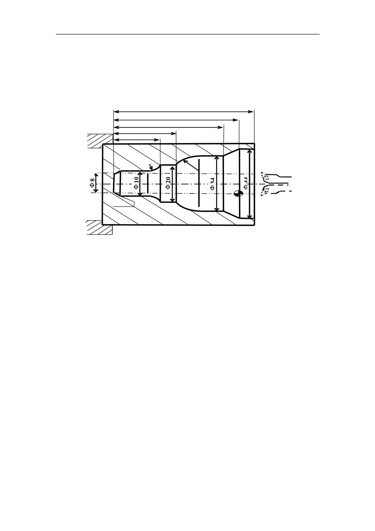
Example 2
The initial point A is (6, 3). The depth of cut is 1.5mm (radius designation). The
retraction amount is 1mm. The finishing allowance in the X direction is 0.6mm, and
the finishing allowance in the Z direction is 0.1mm. The dashed line stands for the
original part.
82
62
52
35
25
R5
R7
2×45
°
Figure 9.19 Internal Diameter Removal without Groove - Example
%3326
N1 T0101
N2 G00 X80 Z80
N3 M03 S400
N4 X6 Z5
G71U1R1P8Q16X-0.6Z0.1 F100
N5 G00 X80 Z80
N6 T0202
N7 G00 G41X6 Z5
N8 G00 X44
N9 G01 Z-20 F80
N10 U-10 W-10
N11 W-10
N12 G03 U-14 W-7 R7
N13 G01 W-10
N14 G02 U-10 W-5 R5
N15 G01 Z-80
N16 U-4 W-2
N17 G40 X4
N18 G00 Z80
N19 X80
N20 M30
118
z Stock Removal in Turning with Groove
Programming
G71 U(△ d) R(r) P(ns) Q(nf) E(e) F(f) S(s) T(t)
Explanation of the parameters
U(△ d)
the cutting depth (radius designation). The cutting direction depends
on the direction of AA’.
R(r)
Retraction amount
P(ns)
Sequence number of the first block for the finishing program.
Q(nf)
Sequence number of the last block for the finishing program.
E(e)
Distance and direction of finishing allowance on X axis. It is positive
when it is outer diameter cutting. It is negative when it is internal diameter cutting.
F(f), S(s), T(t)
F, S, T function are only effective for the rough machining, i.e, it is
not effective in the finishing program - between P(ns) and Q(nf).
B
1 A
r
△d
B’
e
A’
Figure 9.20 Stock Removal in Turning with Groove (G71)
Function
This command can do a stock removal in facing with groove. The machining path
A→A'→B’→B.
119
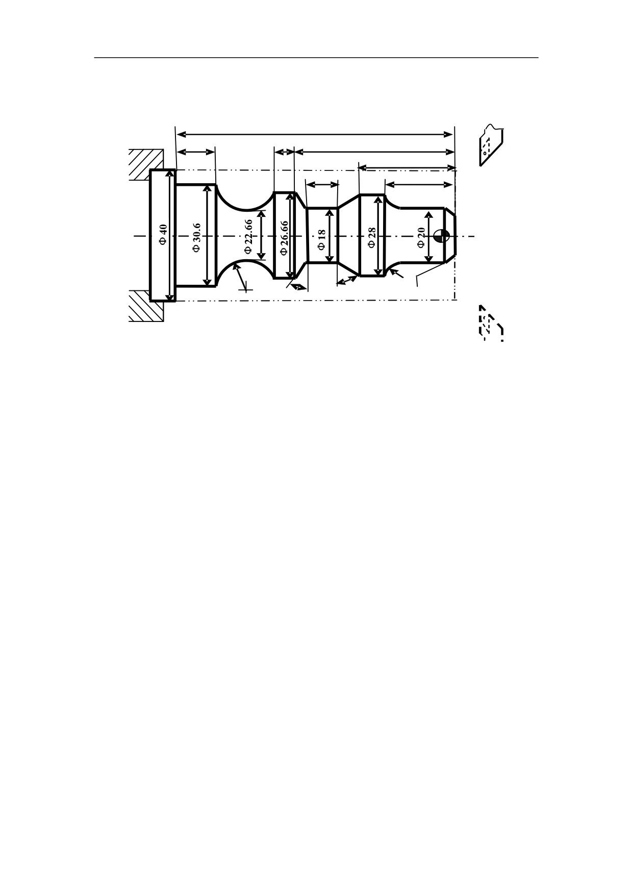
Example
Use G71 to program.
61.5
10
5
32.5
17
(8)
12
2×45°
R10
R4
4
30°
Figure 9.21 Stock Removal in Turning with Groove - Example
%3327
N1 T0101
N2 G00 X80 Z100
M03 S400
N3 G00 X42 Z3
N4G71U1R1P8Q19E0.3F100
N5 G00 X80 Z100
N6 T0202
N7 G00 G42 X42 Z3
N8 G00 X10
N9 G01 X20 Z-2 F80
N10 Z-8
N11 G02 X28 Z-12 R4
N12 G01 Z-17
N13 U-10 W-5
N14 W-8
N15 U8.66 W-2.5
N16 Z-37.5
N17 G02 X30.66 W-14 R10
N18 G01 W-10
N19 X40
N20 G00 G40 X80 Z100
N21 M30
120
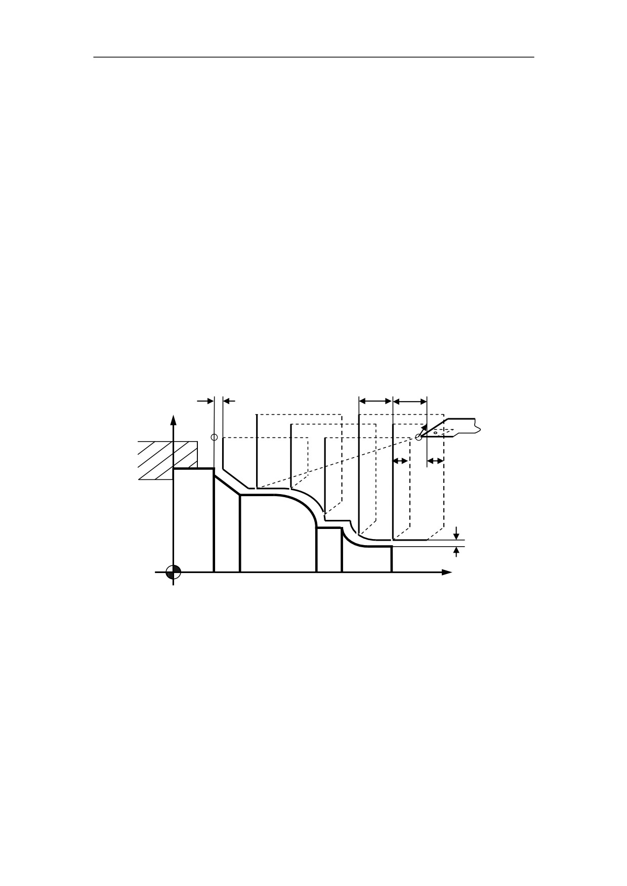
9.2.2 Stock Removal in Facing (G72)
Programming
G72 W(Δd) R(r) P(ns) Q(nf) X(Δx) Z(Δz) F(f) S(s) T(t)
Explanation of the parameters
W(△ d)
the cutting depth (radius designation). The cutting direction depends
on the direction of AA’.
R(r)
Retraction amount
P(ns)
Sequence number of the first block for the finishing program.
Q(nf)
Sequence number of the last block for the finishing program.
X(△ x)
Distance and direction of finishing allowance on X axis
Z(△ z)
Distance and direction of finishing allowance on Z axis
F(f), S(s), T(t)
F, S, T function are only effective for the rough machining, i.e, it is
not effective in the finishing program - between P(ns) and Q(nf).
△z
△d
△d
+X
A’
A
r
r
△x/2
B
+Z
O
Figure 9.22 Stock Removal in Facing (G72)
Function
This command can do a stock removal in facing. The machining path is A→A'→B
121
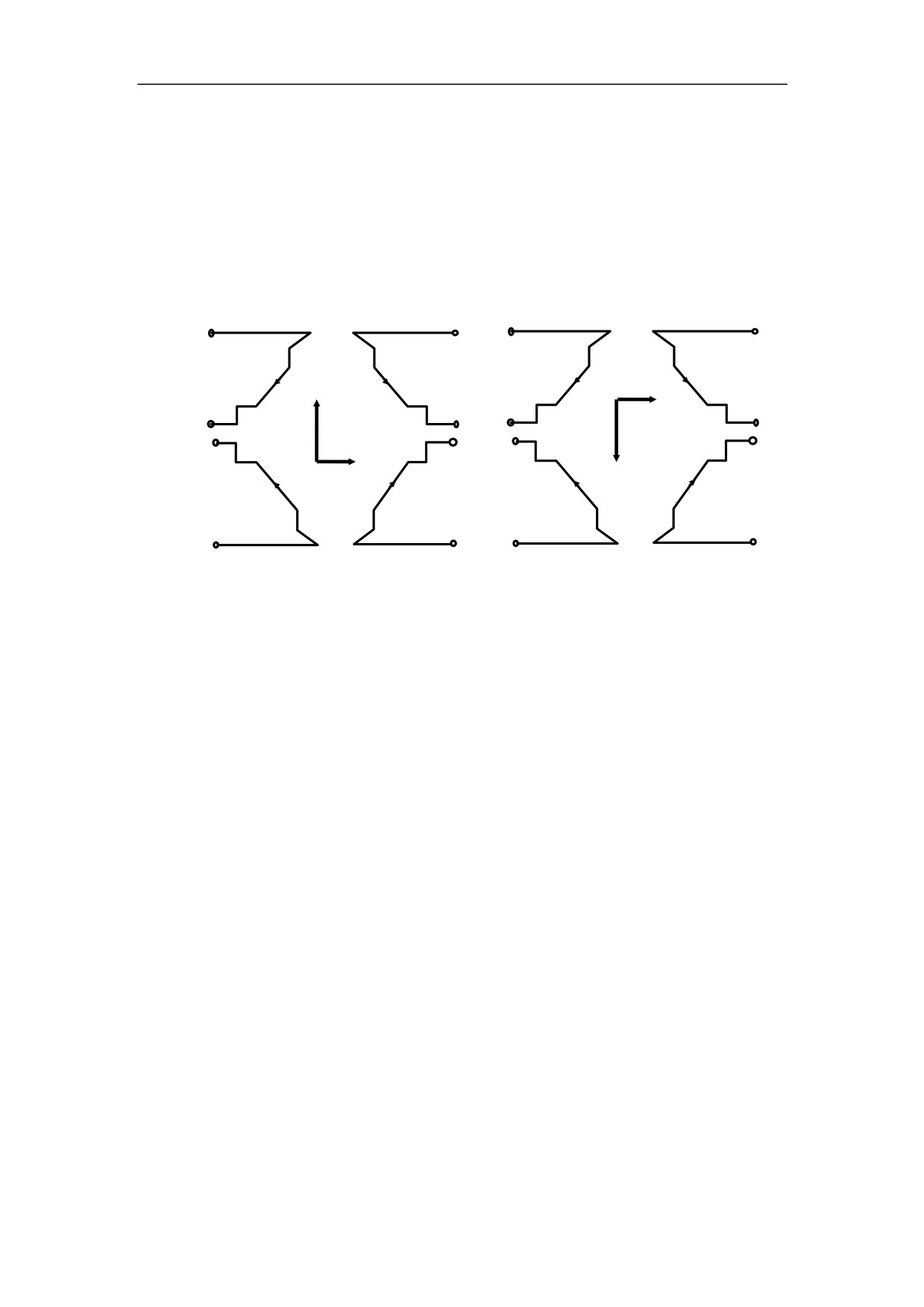
Note
1) G00 or G01 must be used in the finishing program - between P(ns) and Q(nf).
Otherwise, there is an alarm message.
2) G72 cannot be used in MDI mode.
3) G98 and G99 cannot used in the finishing program - between P(ns) and
Q(nf).
4) The direction of △ x and △ z is shown in the following figure.
A
A
A
A'
A'
A
A'
A'
X(+) Z(+)
X(+) Z(-)
X(-) Z(+)
X(-) Z(-)
X
Z
B
B
B
B
B
B
B
B
Z
X
X(-) Z(-)
X(-) Z(+)
X(+) Z(-)
X(+) Z(+)
A
A
A'
A'
A
A'
A'
A
Figure 9.23 Direction of the finishing allowance in G72
122
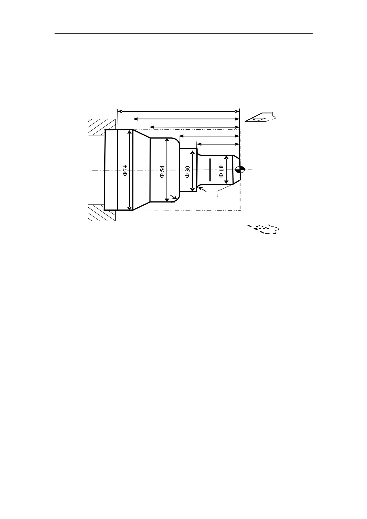
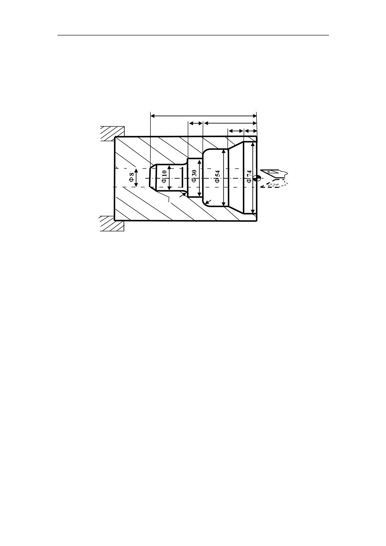
Example 1
Use G72 to program. The initial point A is (80, 1). The depth of cutting is 1.2mm. The
retraction amount is 1mm. The finishing allowance in the X direction is 0.2mm, and
the finishing allowance in the Z direction is 0.5mm. The dashed line stands for the
original part.
60
50
40
26
15
R4
2×45°
R2
Figure 9.24 Outer Diameter Removal in Facing - Example
%3328
N1 T0101
N2 G00 X100 Z80
N3 M03 S400
N4 X80 Z1
N5 G72W1.2R1P8Q17X0.2Z0.5F100
N6 G00 X100 Z80
N7 G42 X80 Z1
N8 G00 Z-53
N9 G01 X54 Z-40 F80
N10 Z-30
N11 G02 U-8 W4 R4
N12 G01 X30
N13 Z-15
N14 U-16
N15 G03 U-4 W2 R2
N16 G01 Z-2
N17 U-6 W3
N18 G00 X50
N19 G40 X100 Z80
N20 M30
123
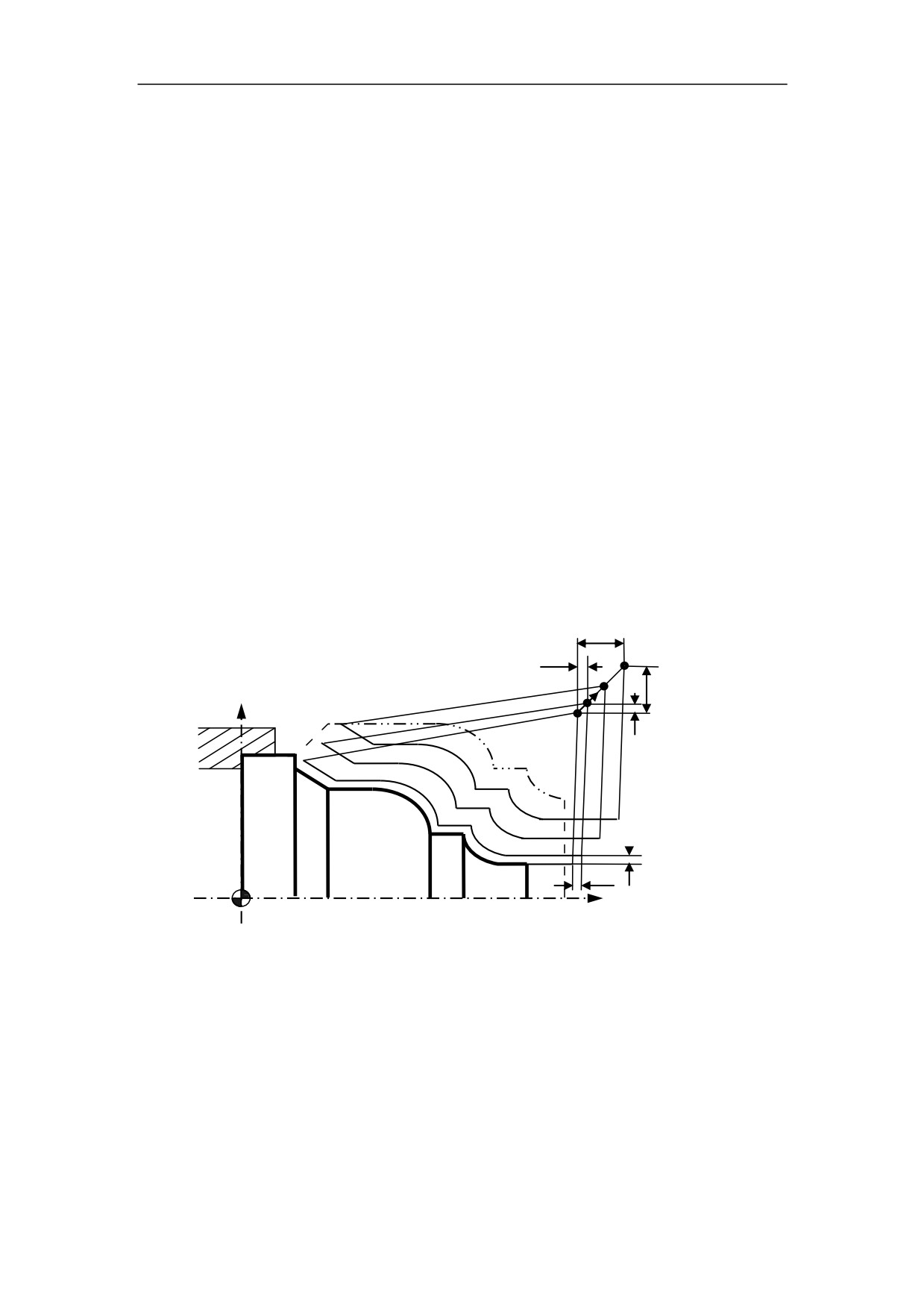
Example 2
Use G72 to program. The initial point A is (80, 1). The depth of cutting is 1.2mm. The
retraction amount is 1mm. The finishing allowance in the X direction is 0.2mm, and
the finishing allowance in the Z direction is 0.5mm. The dashed line stands for the
original part.
60
11
34
10
10
R2
R4
2×45°
Figure 9.25 Internal Diameter Removal in Facing - Example
%3329
N1 T0101
N2 G00 X100 Z80
N3 M03 S400
N4 G00 X6 Z3
N5 G72W1.2R1P5Q15X-0.2Z0.5F100
N6 G00 Z-61
N7 G01 U6 W3 F80
N8 W10
N9 G03 U4 W2 R2
N10 G01 X30
N11 Z-34
N12 X46
N13 G02 U8 W4 R4
N14 G01 Z-20
N15 U20 W10
N16 Z3
N17 G00 X100 Z80
N18 M30
124
9.2.3 Pattern Repeating (G73)
Programming
G73 U(ΔI) W(ΔK) R(r) P(ns) Q(nf) X(Δx) Z(Δz) F(f) S(s) T(t)
Explanation of the parameters
U(△ I)
distance and direction of total roughing allowance in the X direction
(radius designation).
W(△ K)
distance and direction of total roughing allowance in the X direction
(radius designation)
R(r)
Repeated times of cutting
P(ns)
Sequence number of the first block for the finishing program.
Q(nf)
Sequence number of the last block for the finishing program.
X(△ x)
Distance and direction of finishing allowance on X axis
Z(△ z)
Distance and direction of finishing allowance on Z axis
F(f), S(s), T(t)
F, S, T function are only effective for the rough machining, i.e, it is
not effective in the finishing program - between P(ns) and Q(nf).
Δk+Δz
A
1
Δz
+X
ΔI+Δx/2
A
Δx/2
●
B
A
1
A●
’
Δz Δx/2
O
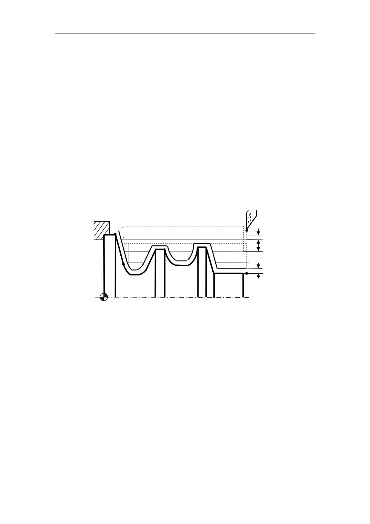
Figure 9.26 Pattern Repeating (G73)
125
Function
G73 command can cut a wokpiece at a fixed pattern repeatedly.
The machining path is A→A'→B.
Note
1) G00 or G01 must be used in the finishing program - between P(ns) and Q(nf).
Otherwise, there is an alarm message.
2) G73 cannot be used in MDI mode.
3) G98 and G99 cannot used in the finishing program - between P(ns) and
Q(nf).
4) The depth for each cutting on X axis = △ I/r
The depth for each cutting on Z axis = △ K/r
5) The direction of △ I and △ K, and the direction of △ x and △ z should be
noted.
126
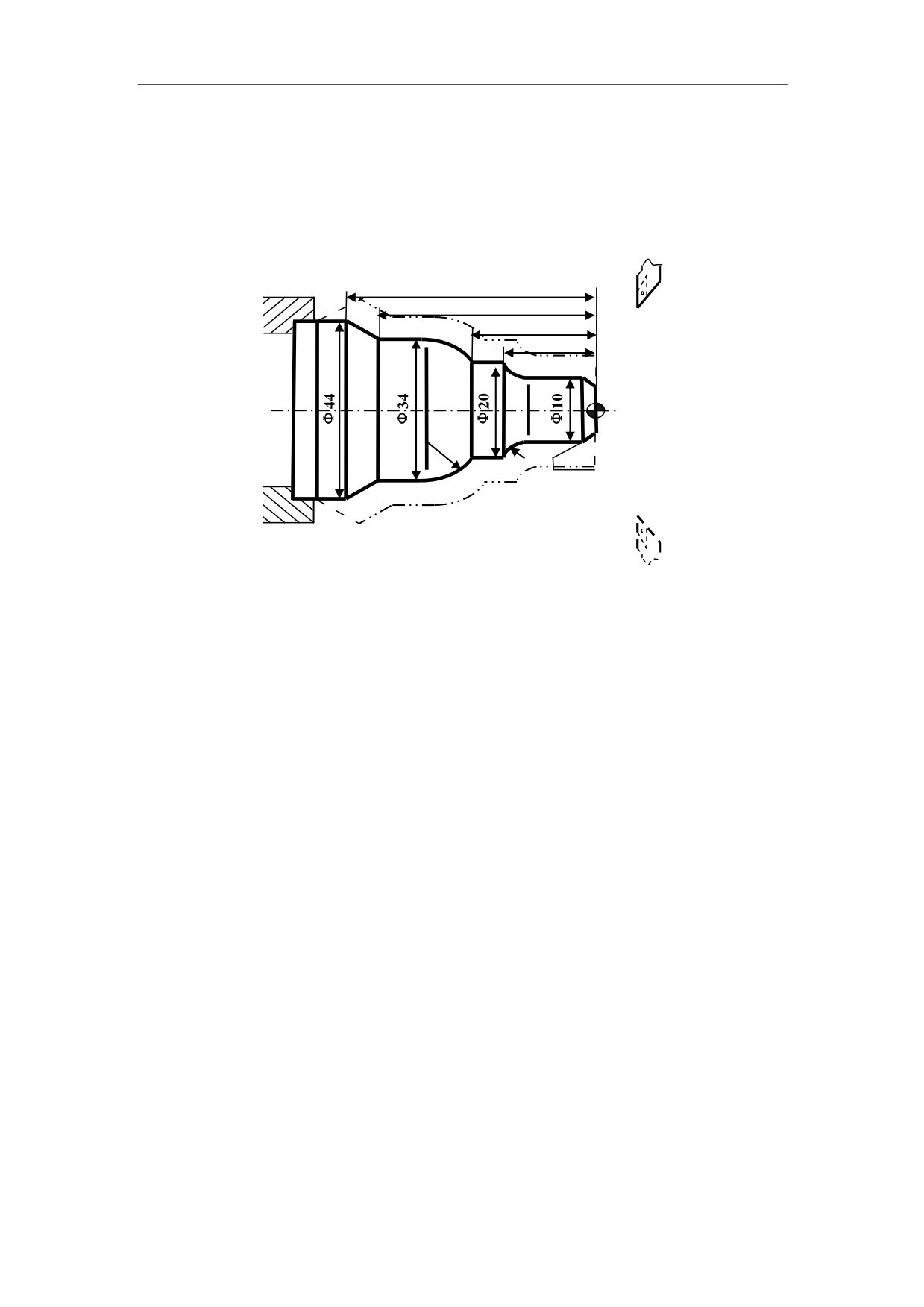
Example
Use G73 to program. The initial point A is (60, 5). The total roughing allowance on X
and Z axis are 3mm, 0.9mm, respectively. The times of rough cutting is 3. The
finishing allowance on X and Z axis are
0.6mm,
0.1mm respectively. The
dash-dot-line is the part’s blank.
62
52
35
25
R7
R5
2×45°
Figure 9.27 Pattern Repeating - Example
%3330
N1 T0101
N2 G00 X80 Z80
N3 M03 S400
N4 G00 X60 Z5
N5 G73U3W0.9R3P5Q13X0.6Z0.1F120
N6 G00 X0 Z3
N7 G01 U10 Z-2 F80
N8 Z-20
N9 G02 U10 W-5 R5
N10 G01 Z-35
N11 G03 U14 W-7 R7
N12 G01 Z-52
N13 U10 W-10
N14 U10
N15 G00 X80 Z80
N16 M30
127
9.2.4 Multiple Thread Cutting Cycle (G76)
Programming
G76 C(c) R(r) E(e) A(a) X(x) Z(z) I(i) K(k) U(d) V(Δdmin) Q(Δd) P(p) F(L) O
Explanation of the parameters
C(c)
Repetitive count in finishing (1~99), modal value
R(r)
Retraction amount on Z axis (00~99), modal value
E(e)
Retraction amount on X axis (00~99), modal value
A(a)
Angle of tool tip (two-digit number), modal value. It must be more than
10° and less than 80°.
X, Z
Coordinate value of end point (point C) in absolute command.
x, z
Coordinate value of end point (point C) with reference to the initial point
(point A) in incremental command
I(i)
Difference of thread radius. If i=0, it is straight thread cutting.
K(k)
Height of thread. This value is specified by the radius value on X axis.
U(d)
The finishing allowance (radius) (Figure 9.29).
V(Δdmin) The minimum cutting depth (radius). The cutting depth is Δdmin when
the cutting depth (d
n d
n1) is less than Δdmin (Figure 9.29).
Q(Δd)
Depth of cutting at the first cut (radius)
P(p)
spindle angle of spindle reference pulse to the start point of cutting
F(L)
Thread lead (same as G32)
O
Acceleration constant of thread cutting retraction. When it is set to zero,
the acceleartion is maximum. The more this value is, the acceleration time is longer,
and the retraction is longer. Q must be set to zero or more than zero. O is modal code.
+X
A
D
(R)
(R)
u/2
(R)
(F)
e
d
K
i
C
r
B
x/2
z
w
+Z
Figure 9.28 Multiple Thread Cutting Cycle (G76)
128
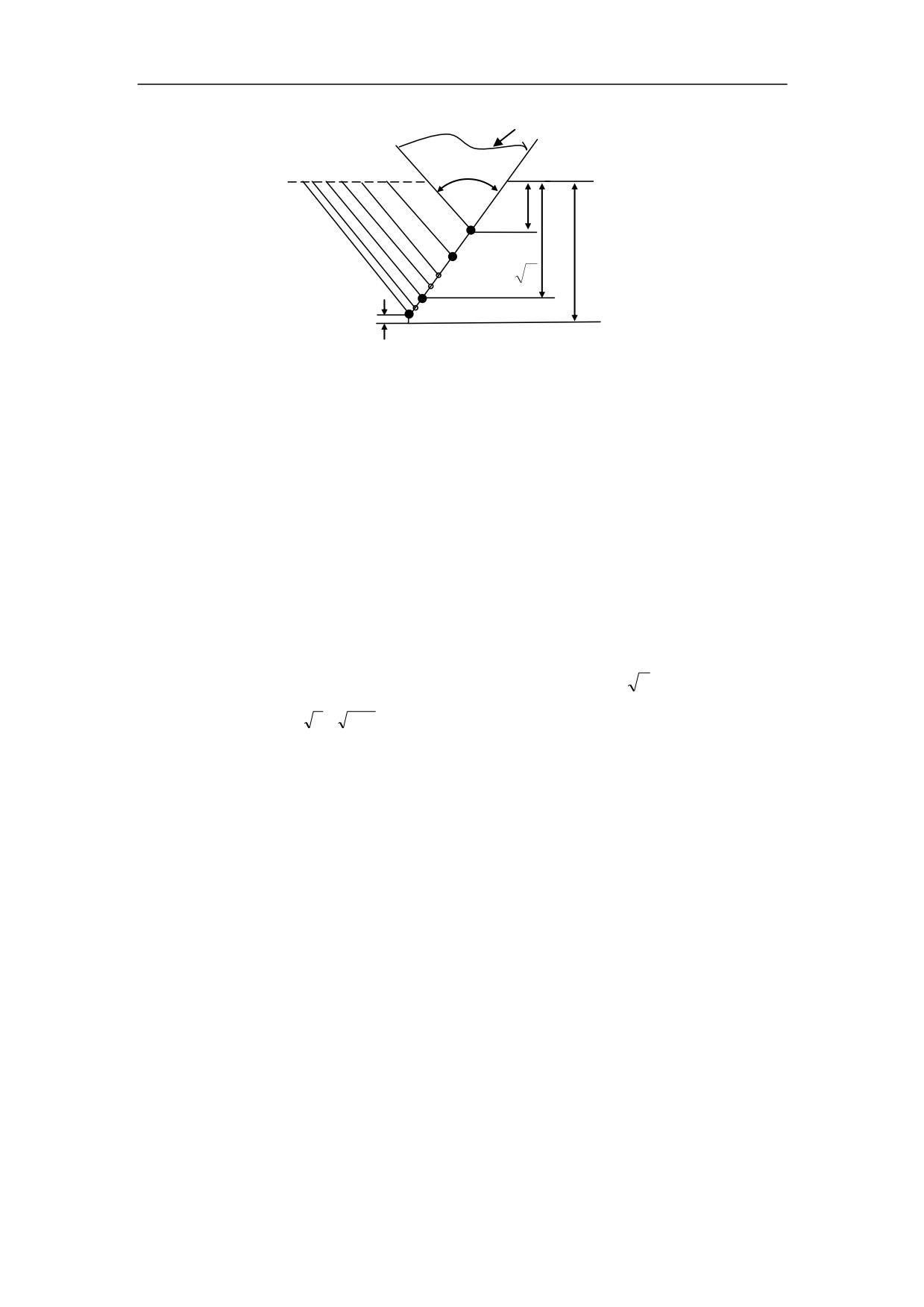
Angle of tool tip
a
Δd
1st
k
2nd
Δd
n
d
nth
Figure 9.29 The depth of cutting
Function
G76 command can do the multiple thread cutting. The machining path is
A→B→C→D.
Note
1) In G76, X(x) and Z(z) realize cycle machining. When incremental
programming, note the sign of x and w (determined by the direction of tool
path of AC and CD).
2) G76 cycle do singal-side cutting to reduce the stress of tool point. The cutting
depth in 1st cut is Δd, the cutting depth in nth cut is
d
n . The bite of each
d(
n
n
1
)
cycle is
3) The cutting speed of CD path is specified by feedrate. And the other paths
are specified by rapid traverse speed.
129
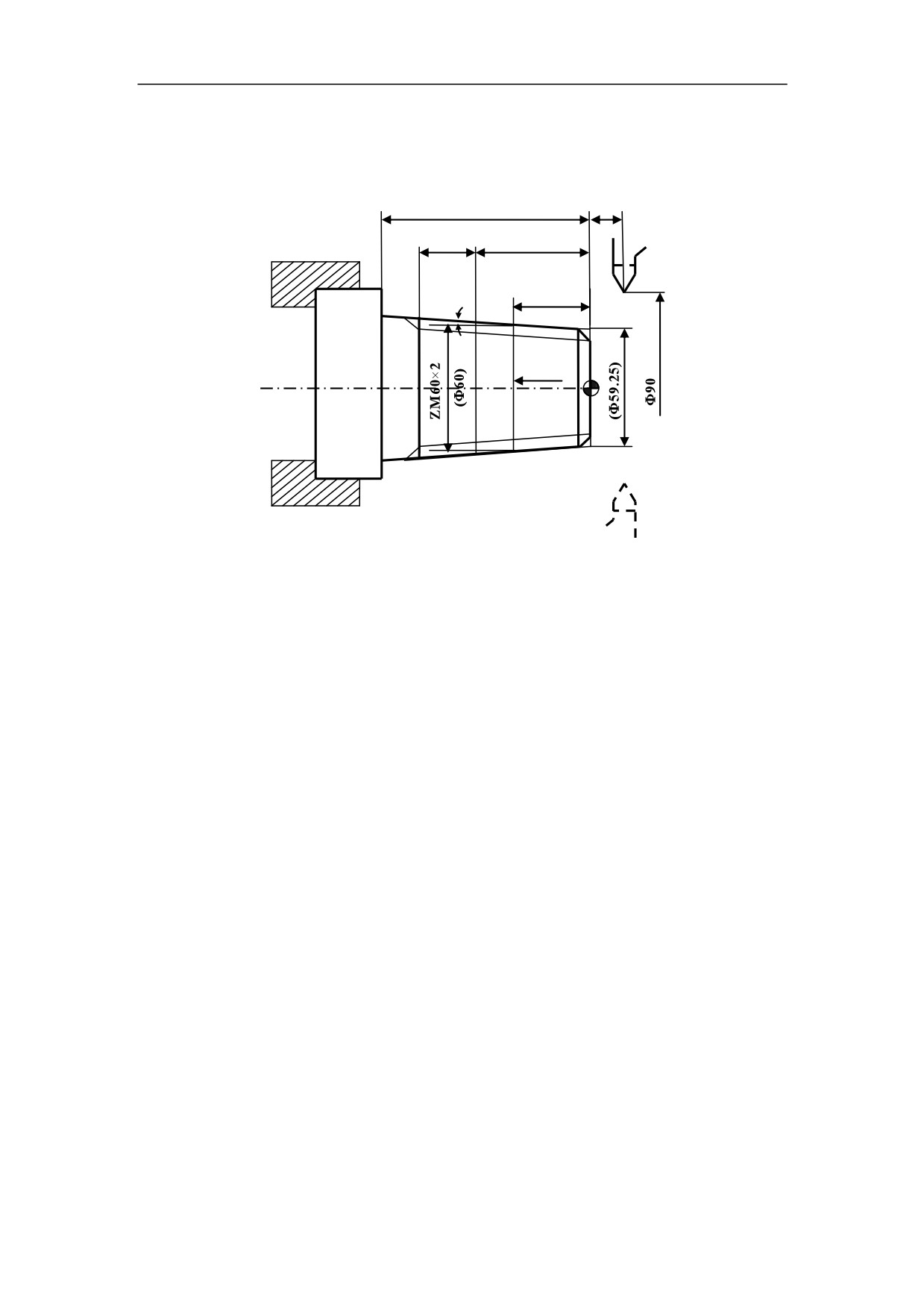
Example
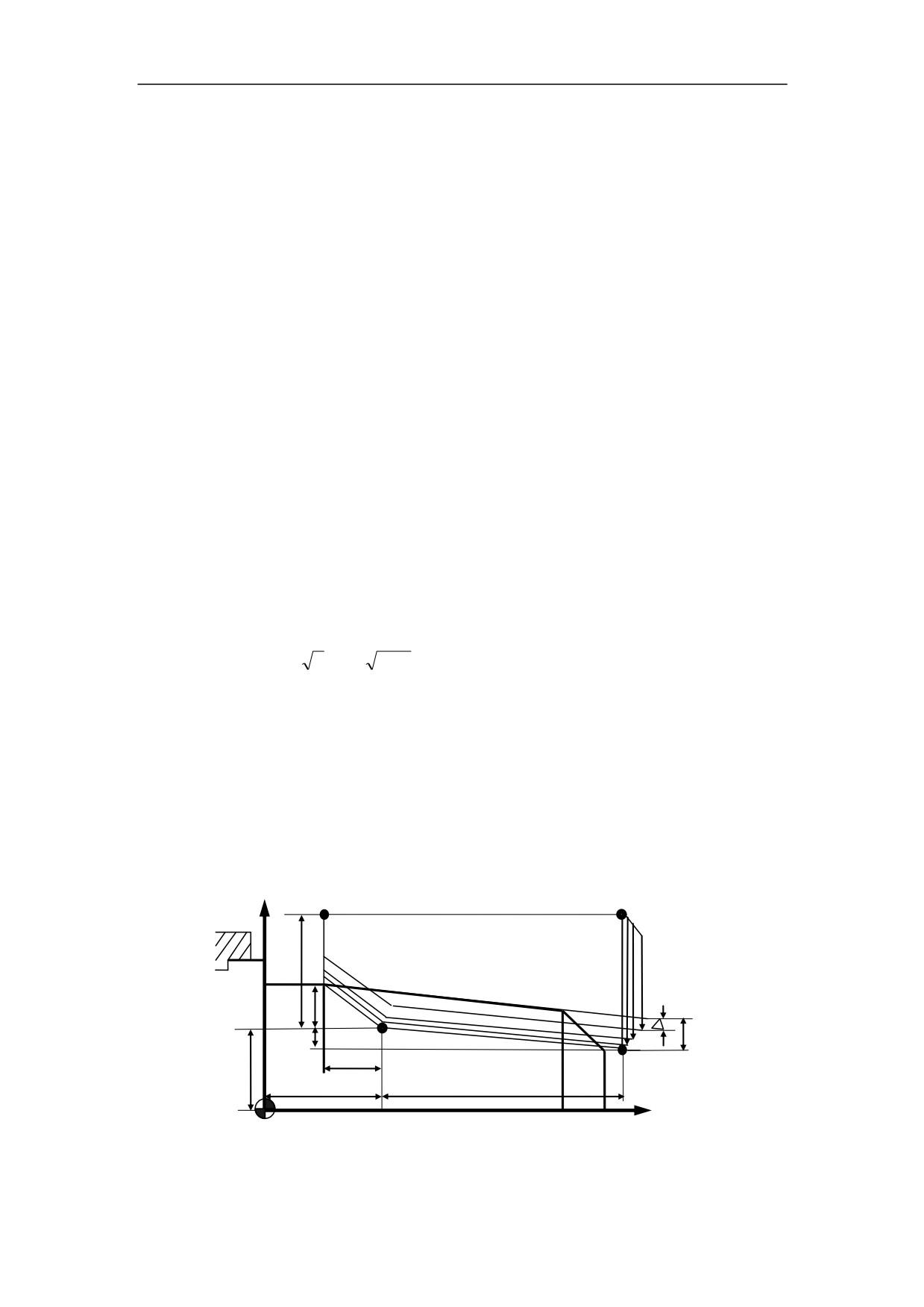
Use G76 to program. The thread is ZM60×2. Sizes in bracket is from standards.
(tan1.79=0.03125)
30
4
6
(18)
(12)
(1.79°)
Figure 9.30 Multiple Thread Cutting Cycle - Example
%3331
N1 T0101
; Change No.1 tool, set its coordiante
N2 G00 X100 Z100
; To start of program or the position of changing tool
N3 M03 S400
; Spindle CW 400r/min
N4 G00 X90 Z4
; To the position of simple cycle start
N5 G80 X61.125 Z-30 I-1.063 F80 ; Machining cone thread surface
N6 G00 X100 Z100 M05
;To the position of program start or tool change
N7 T0202
; Change No.2 tool, set its coordiante
N8 M03 S300
; Spindle CW 300r/min
N9 G00 X90 Z4
; To the positon of thread cycle start
N10 G76C2R-3E1.3A60X58.15Z-24I-0.875K1.299U0.1V0.1F2
N11 G00 X100 Z100
; Return to start or change tool position
N12 M05
; Return to start or change tool position
N13 M30
; Main program end and reset
130
10. Comprehensive Programming
10 Comprehensive Programming
10.1 Example 1
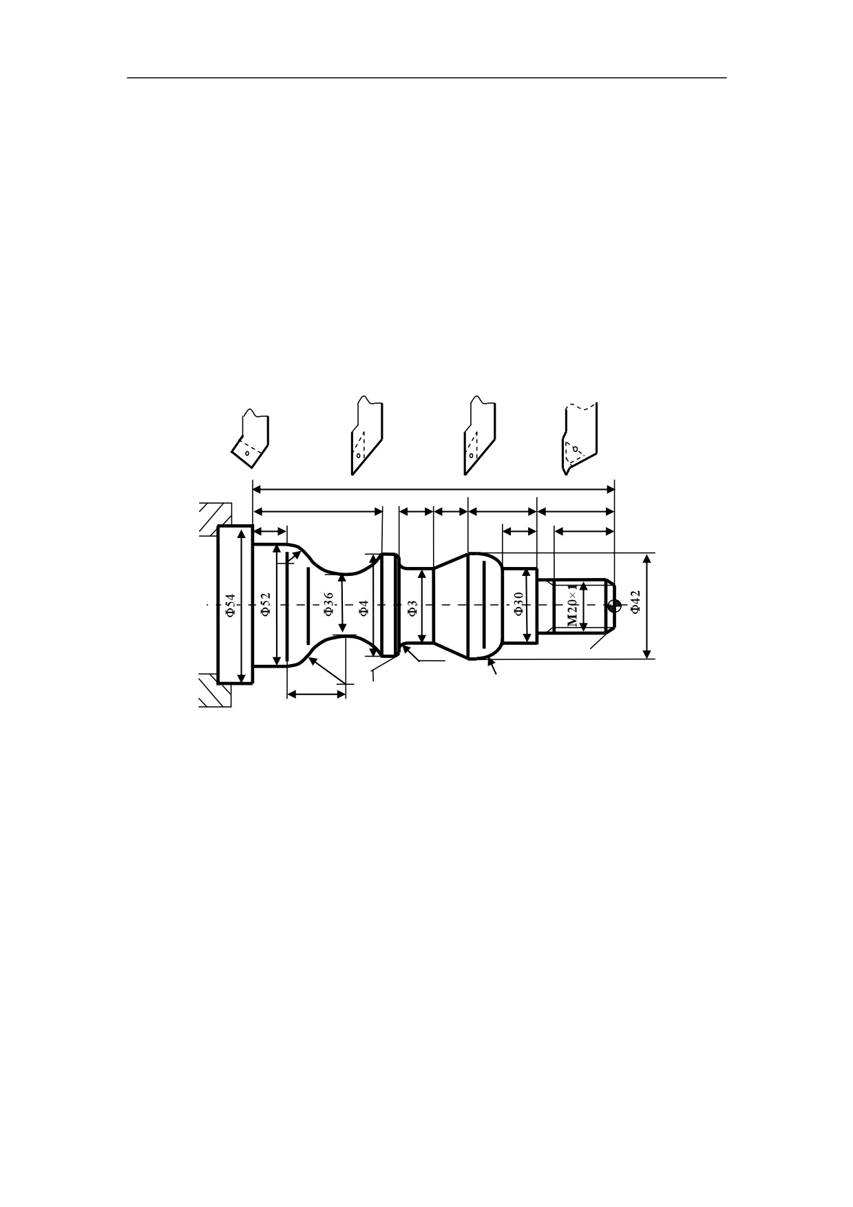
Program for the part shown in the figure. The processing condition: material: #45 steel,
or aluminum; diameter of the part is Φ54mm, length of the part is 200mm. Tool
selection: number 1 face tool is used to machine the part face, number 2 face
cylindrical tool is used to rough turning the contour, number 3 face cylindrical tool is
used to finish turning the contour, and number 4 cylindrical triple screw is used to
machine the thread whose lead is 3mm, pitch is 1mm.
133
50
10
12
20
33
11
10
26
R15
2×45°
R2
R25
R6
1×45°
24
Figure 10.1 Comprehensive Program Example 1
%3365
N1 T0101
N2 M03 S500
N3 G00 X100 Z80
N4 G00 X60 Z5
N5 G81 X0 Z1.5 F100
N6 G81 X0 Z0
N7 G00 X100 Z80
N8 T0202
N9 G00 X60 Z3
N10 G80 X52.6 Z-133 F100
N11 G01 X54
N12 G71 U1 R1 P16 Q32 E0.3
131
10. Comprehensive Programming
N13 G00 X100 Z80
N14 T0303
N15 G00 G42 X70 Z3
N16 G01 X10 F100
N17 X19.95 Z-2
N18 Z-33
N19 G01 X30
N20 Z-43
N21 G03 X42 Z-49 R6
N22 G01 Z-53
N23 X36 Z-65
N24 Z-73
N25 G02 X40 Z-75 R2
N26 G01 X44
N27 X46 Z-76
N28 Z-84
N29 G02 Z-113 R25
N30 G03 X52 Z-122 R15
N31 G01 Z-133
N32 G01 X54
N33 G00 G40 X100 Z80
N34 M05
N35 T0404
N36 M03 S200
N37 G00 X30 Z5
N38G82X19.3Z-26R-3E1C2P120F3
N39G82X18.9Z-26R-3E1C2P120F3
N40G82X18.7Z-26R-3E1C2P120F3
N41G82X18.7Z-26R-3E1C2P120F3
N42 G76C2R-3E1A60X18.7Z-26 K0.65U0.1V0.1Q0.6P240F3
N43 G00 X100 Z80
N44 M30
132
10. Comprehensive Programming
10.2 Example 2
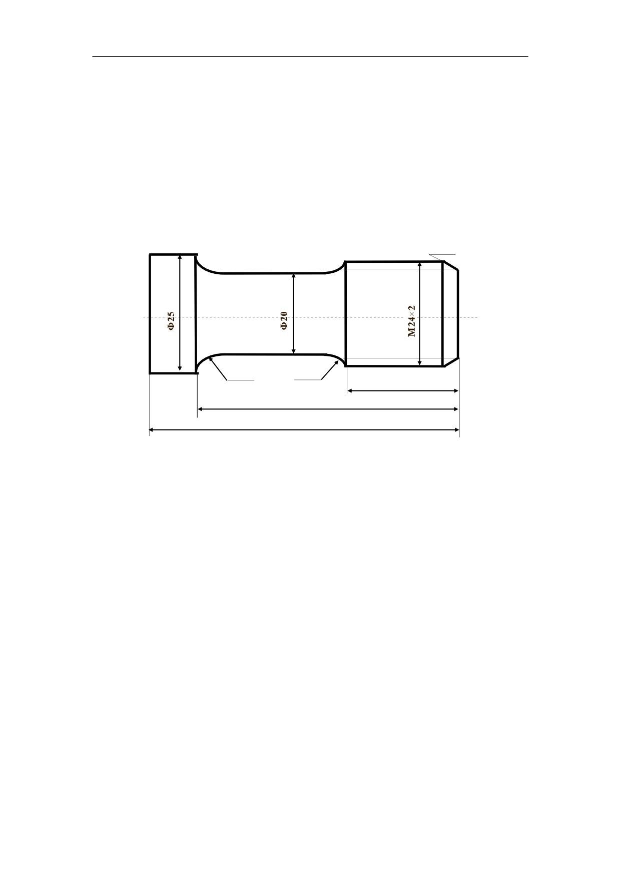
Program for the part shown in the figure. The processing condition: material: #45 steel,
or aluminum; diameter of the part is Φ26mm, length of the part is 70mm. Tool
selection: number 1 cylindrical tool is used to rough turning the contour, number 2
cylindrical tool is used to finish turning the contour, number 3 cylindrical thread tool is
used to machine the thread. The pitch is 2mm. At last, number 4 parting-off tool is
used to cut off the part.
2×45°
R10
R10
18
38
45
Figure 10.2 Comprehensive Programming Example 2
%3368
N1 T0101
N2 M03 S600
N3 G00 X100 Z30
N4 G00 X27 Z3
N5 G71 U1 R1 P9 Q E0.2 F100
N6 G00 X100 Z30
N7 T0202
N8 G00 G41 X27 Z3
N9 G00 X14 Z3
N10 G01 X24 Z-2 F80
N11 Z-18
N12 G02 X20 Z-24 R10
N13 G01 Z-31.39
N14 G02 X25 W-6.61 R10
N15 G01 Z-45
133
10. Comprehensive Programming
N16 G00 X30
N17 G40 X100 Z30
N18 T0303
N19 G00 X27 Z3
N20 G82 X23.1 Z-22 F2
N21 G82 X22.5 Z-22 F2
N22 G82 X21.9 Z-22 F2
N23 G82 X21.5 Z-22 F2
N24 G82 X21.4 Z-22 F2
N25 G82 X21.4 Z-22 F2
N26 G00 X100 Z30
N27 T0404
N28 G00 X30 Z-45
N29 G01 X3 F50
N30 G00 X100
N31 Z30
N13 M30
134
10. Comprehensive Programming
10.3 Example 3
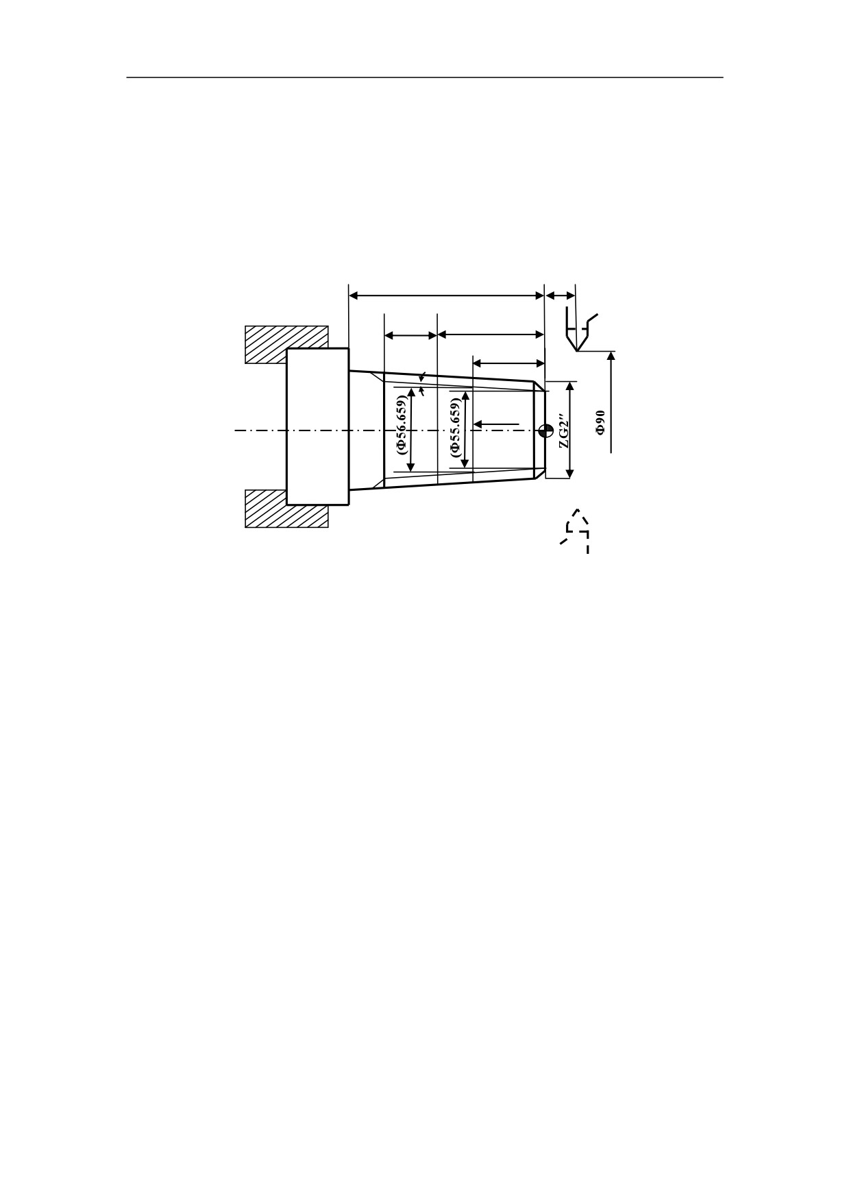
Program for the tapered thread ZG2″ shown in the figure. According to the standard,
the pitch is 2.309mm(25.4/11), the thread height is 1.479mm. Other sizes are shown
in the figure. The depth of cut at each time is separately(diameter designation) 1mm,
0.7 mm, 0.6mm , 0.4mm and 0.26mm, and the angle of tool tip is 55° (tan1.79=0.031).
40
4
4
(26)
(16)
(1.79°)
Figure 10.3 Comprehensive Programming Example 3
%3366
N1 T0101
N2 M03 S300
N3 G00 X100 Z100
N4 X90 Z4
N5 G80 X61.117 Z-40 I-1.375 F80
N6 G00 X100 Z100
N7 T0202
N8 G00 X90 Z4
N9 G82 X59.494 Z-30 I-1.063 F2.31
N10 G82 X58.794 Z-30 I-1.063 F2.31
N11 G82 X58.194 Z-30 I-1.063 F2.31
N12 G82 X57.794 Z-30 I-1.063 F2.31
N13 G82 X57.534 Z-30 I-1.063 F2.31
N14 G00 X100 Z100
N15 M30
135
10. Comprehensive Programming
10.4 Example 4
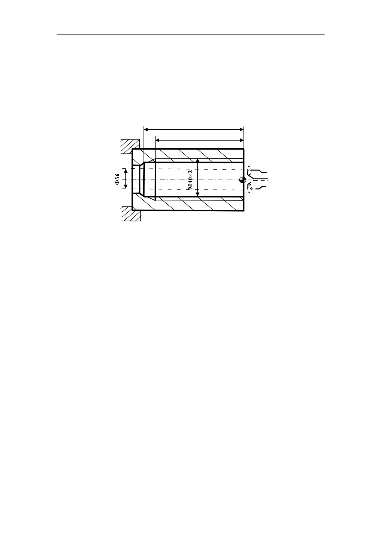
Program for the M40×2 inner thread shown in the figure. According to the standard,
the pitch is 2.309mm(25.4/11), thread height is 1.299mm. Other sizes are shown in
the figure. The depth of cut at each time(diameter designation) is 0.9mm, 0.6mm,
0.6mm, 0.4mm and 0.1mm. The angle of tool tip is 60°.
38
30
Figure 10.4 Comprehensive Programming Example 4
%3367
N1 T0101
N2 M03 S300
N3 G00 X100 Z100
N4 X20 Z4
N5 G80 X37.35 Z-38 F80
N6 G00 X100 Z100
N7 T0202
N8 G00 X20 Z4
N9 G82 X38.25 Z-30 R-4 E-1.3 F2
N10 G82 X38.85 Z-30 R-4 E-1.3 F2
N11 G82 X39.45 Z-30 R-4 E-1.3 F2
N12 G82 X39.85 Z-30 R-4 E-1.3 F2
N13 G82 X39.95 Z-30 R-4 E-1.3 F2
N14 G00 X100 Z100
N15 M30
136
11. Custom Macro
11 Custom Macro
Similarly to subprogram, the custom macro function allows operators to define their
own program. The way of calling the custom macro is same as subprogram’s.
The difference is that custom macro allows use of variables, arithmetic and logic
operations, selection and repetition.
137

11. Custom Macro
11.1 Variables
Format and Explanation
#_
Variable is composed of a number sign (#) and a number.
Example
#1
#1=#2+100
11.1.1 Type of Variables
There are four types of variables.
Table 11-1 Type of Variables
Variable
Type of variables
Function
number
They are used in a
macro
#0~#49
Local variables
program.
They can be shared
among
#50~#199
Common variables
different macro programs.
#200~#249
0 layers local variables
#250~#299
1 layers local variables
#300~#349
2 layers local variables
#350~#399
3 layers local variables
#400~#449
4 layers local variables
#450~#499
5 layers local variables
#500~#549
6 layers local variables
#550~#599
7 layers local variables
They are used to read and write
#600~
System variables
NC data.
Note:
1) The operator can only use the #0~#599 local variables for programming.
2) Variables after #599 can only be used by the system programmer for reference.
138
11. Custom Macro
11.1.2 System Variables
#1000
“current position X in machine coordinate system”
#1001
“current position Y in machine coordinate system”
#1002
“current position Z in machine coordinate system”
#1003
“current position A in machine coordinate system”
#1004
“current position B in machine coordinate system”
#1005
“current position X in machine coordinate system”
#1006
“current position U in machine coordinate system”
#1007
“current position V in machine coordinate system”
#1008
“current position W in machine coordinate system”
#1009
“diameter programming”
#1010
“position X - machine coordinate system in programming”
#1011
“position Y - machine coordinate system in programming”
#1012
“position Z - machine coordinate system in programming”
#1013
“position A - machine coordinate system in programming”
#1014
“position B - machine coordinate system in programming”
#1015
“position C - machine coordinate system in programming”
#1016
“position U - machine coordinate system in programming”
#1017
“position V - machine coordinate system in programming”
#1018
“position W - machine coordinate system in programming”
#1019
reserved
#1020
“position X - workpiece coordinate system in programming”
#1021
“position Y - workpiece coordinate system in programming”
#1022
“position Z - workpiece coordinate system in programming”
#1023
“position A - workpiece coordinate system in programming”
#1024
“position B - workpiece coordinate system in programming”
#1025
“position C - workpiece coordinate system in programming”
#1026
“position U - workpiece coordinate system in programming”
#1027
“position V - workpiece coordinate system in programming”
#1028
“position W - workpiece coordinate system in programming”
#1029
reserved
#1030
“origin X in workpiece coordinate system”
#1031
“origin Y in workpiece coordinate system”
#1032
“origin Z in workpiece coordinate system”
#1033
“origin A in workpiece coordinate system”
139
11. Custom Macro
#1034
“origin B in workpiece coordinate system”
#1035
“origin C in workpiece coordinate system”
#1036
“origin U in workpiece coordinate system”
#1037
“origin V in workpiece coordinate system”
#1038
“origin W in workpiece coordinate system”
#1039
“axis of the coordinate system”
#1040
“origin X of G54”
#1041
“origin Y of G54”
#1042
“origin Z of G54”
#1043
“origin A of G54”
#1044
“origin B of G54”
#1045
“origin C of G54”
#1046
“origin U of G54”
#1047
“origin V of G54”
#1048
“origin W of G54”
#1049
reserved
#1050
“origin X of G55”
#1051
“origin Y of G55”
#1052
“origin Z of G55”
#1053
“origin A of G55”
#1054
“origin B of G55”
#1055
“origin C of G55”
#1056
“origin U of G55”
#1057
“origin V of G55”
#1058
“origin W of G55”
#1059
reserved
#1060
“origin X of G56”
#1061
“origin Y of G56”
#1062
“origin Z of G56”
#1063
“origin A of G56”
#1064
“origin B of G56”
#1065
“origin C of G56”
#1066
“origin U of G56”
#1067
“origin V of G56”
#1068
“origin W of G56”
#1069
reserved
#1070
“origin X of G57”
140
11. Custom Macro
#1071
“origin Y of G57”
#1072
“origin Z of G57”
#1073
“origin A of G57”
#1074
“origin B of G57”
#1075
“origin C of G57”
#1076
“origin U of G57”
#1077
“origin V of G57”
#1078
“origin W of G57”
#1079
reserved
#1080
“origin X of G58”
#1081
“origin Y of G58”
#1082
“origin Z of G58”
#1083
“origin A of G58”
#1084
“origin B of G58”
#1085
“origin C of G58”
#1086
“origin U of G58”
#1087
“origin V of G58”
#1088
“origin W of G58”
#1089
reserved
#1090
“origin X of G59”
#1091
“origin Y of G59”
#1092
“origin Z of G59”
#1093
“origin A of G59”
#1094
“origin B of G59”
#1095
“origin C of G59”
#1096
“origin U of G59”
#1097
“origin V of G59”
#1098
“origin W of G59”
#1099
reserved
#1100
“break point X”
#1101
“break point Y”
#1102
“break point Z”
#1103
“break point A”
#1104
“break point B”
#1105
“break point C”
#1106
“break point U”
#1107
“break point V”
141
11. Custom Macro
#1108
“break point W”
#1109
“axis of the coordinate system”
#1110
“middle point X of G28”
#1111
“middle point Y of G28”
#1112
“middle point Z of G28”
#1113
“middle point A of G28”
#1114
“middle point B of G28”
#1115
“middle point C of G28”
#1116
“middle point U of G28”
#1117
“middle point V of G28”
#1118
“middle point W of G28”
#1119
“shield of G28”
#1120
“mirror-image position X”
#1121
“mirror-image position Y”
#1122
“mirror-image position Z”
#1123
“mirror-image position A”
#1124
“mirror-image position B”
#1125
“mirror-image position C”
#1126
“mirror-image position U”
#1127
“mirror-image position V”
#1128
“mirror-image position W”
#1129
“shield of mirror image”
#1130
“rotational axis 1”
#1131
“rotational axis 2”
#1132
“rotation angle”
#1133
“shield of rotational axis”
#1134
reserved
#1135
“scale axis 1”
#1136
“scale axis 2”
#1137
“scale axis 3”
#1138
“scaling”
#1139
“shield of scale axis”
#1140
“code 1 of changing a coordinate system”
#1141
“code 2 of changing a coordinate system”
#1142
“code 3 of changing a coordinate system”
#1143
reserved
#1144
“number of tool length compensation”
142
11. Custom Macro
#1145
“number of tool radius compensation”
#1146
“linear axis 1”
#1147
“linear axis 2”
#1148
“shield of virtual axis”
#1149
“specified feedrate”
#1150
“modal value of G code - 0”
#1151
“modal value of G code - 1”
#1152
“modal value of G code - 2”
#1153
“modal value of G code - 3”
#1154
“modal value of G code - 4”
#1155
“modal value of G code - 5”
#1156
“modal value of G code - 6”
#1157
“modal value of G code - 7”
#1158
“modal value of G code - 8”
#1159
“modal value of G code - 9”
#1160
“modal value of G code - 10”
#1161
“modal value of G code - 11”
#1162
“modal value of G code - 12”
#1163
“modal value of G code - 13”
#1164
“modal value of G code - 14”
#1165
“modal value of G code - 15”
#1166
“modal value of G code - 16”
#1167
“modal value of G code - 17”
#1168
“modal value of G code - 18”
#1169
“modal value of G code - 19”
#1170
“residual CACHE”
#1171
“spare CACHE”
#1172
“residual buffer storage”
#1173
“spare buffer storage”
#1174
reserved
#1175
reserved
#1176
reserved
#1177
reserved
#1178
reserved
#1179
reserved
#1180
reserved
#1181
reserved
143
11. Custom Macro
#1182 reserved
#1183 reserved
#1184 reserved
#1185 reserved
#1186 reserved
#1187 reserved
#1188 reserved
#1189 reserved
#1190
“customized input”
#1191
“customized output”
#1192
“customized output shield”
#1193 reserved
#1194 reserved
#2000~#2600
data for the repetitive cycle
#2000
number of contour point
#2001~#2100 type of contour (0: G00, 1: G01, 2: G02, 3: G03)
#2101~#2200 contour point X (diameter or radius designation)
#2201~#2300 contour point Z
#2301~#2400 contour point R
#2401~#2500 contour point I
#2501~#2600 contour point J
11.1.3 Memorable User-defined Variables
CNC provides 100 memorable user-defined variables #1300~#1399. The methods
are as followed:
1. Set the initial value of macro variables
2. Add M94 where the macro is saved in the program
144
11. Custom Macro
11.2 Constant
PI
π, 3.14151926
TRUE True condition
FALSE False condition
145