Century Star Turning CNC System. Programming Guide (V3.5 April, 2015) - page 4
7. Tool Function
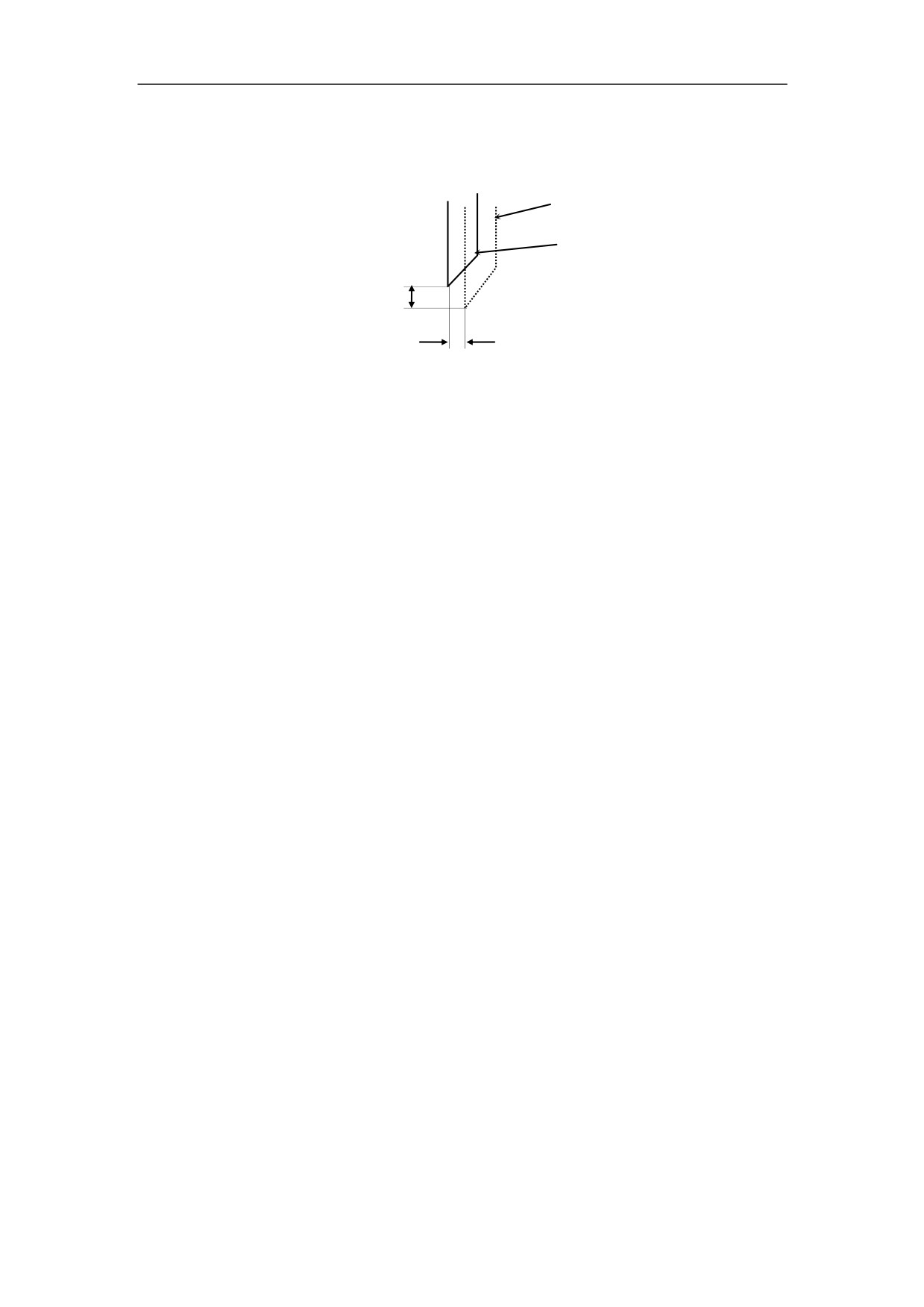
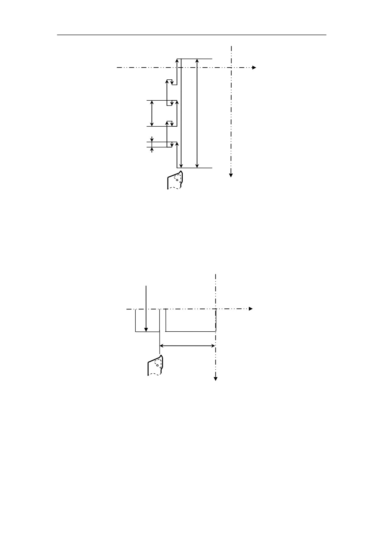
Standard offset is the directed distance of the workpiece origin relative to the standard
tool position on the cutter frame.
Standard tool
Non-standard Tool
Offset compensation on axis Z
B
△x
A
△z
Offset compensation on axis Z
Figure 7.3 Incremental tool offset compensation
If there is tool setting gauge, the following steps are for the measurement of relative
tool offset:
1) Move the standard tool to the cross center of tool setting gauge.
2) Press MDI function key, and set the current position of tool as the relative
origin.
3) Change a tool and move the other tool to the cross center of tool setting
gauge. The shown value is the offset relative to the standard tool.
If there is no tool setting gauge, the following steps are for the measurement of
relative tool offset:
1) Press “MDI” function key, and set the current position of axis Z as the relative
origin in the trial face cutting of the workpiece. (no movement on axis Z before
setting zero).
2) Press “MDI” function key, and set the current position of axis X as the relative
origin in the trial cylindrical surface cutting of the workpiece (no movement on
axis X before setting zero). The standard tool has set a reference point on the
workpiece. When the standard tool is at the reference point, it is the position
of the relative origin.
3) Change a tool and move the another tool to the reference point of workpiece.
The shown value is the offset relative to the standard tool.
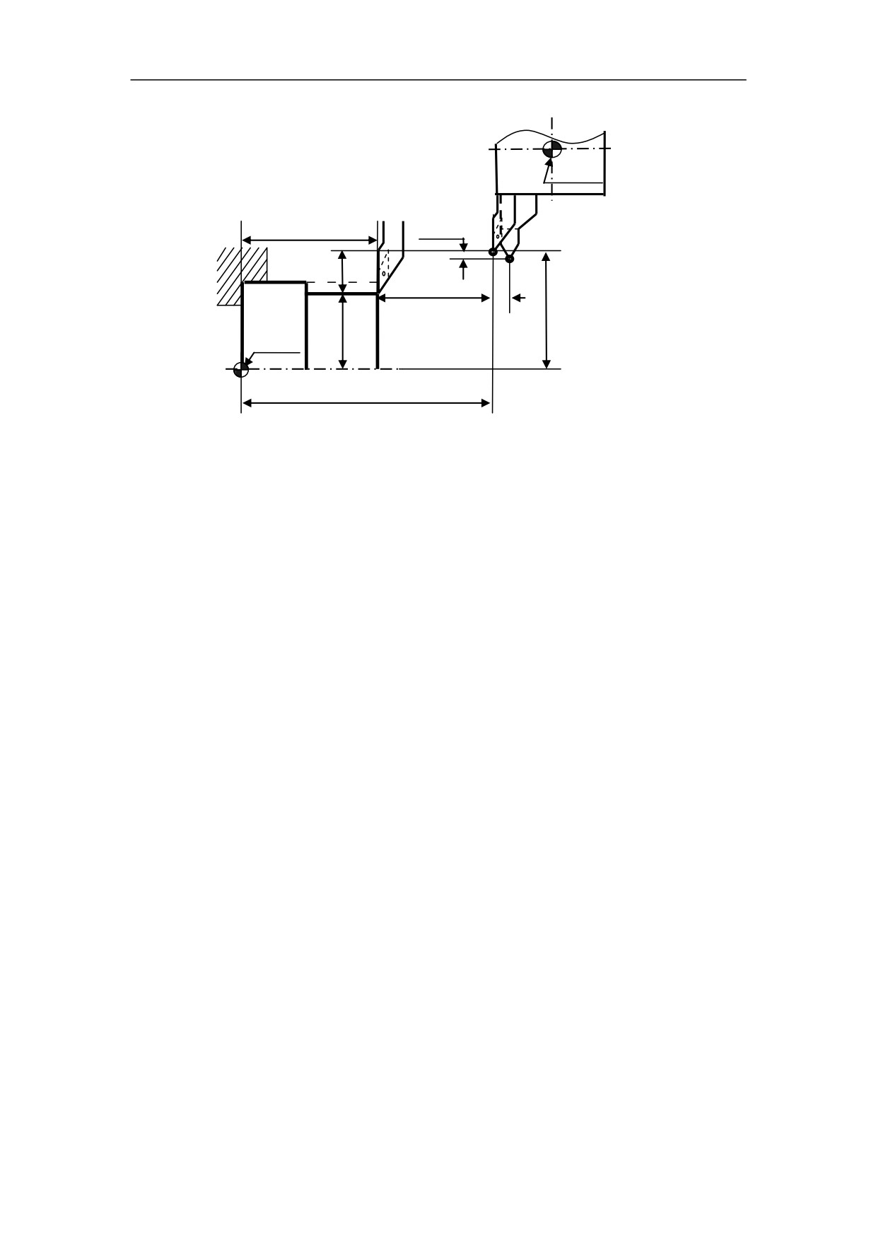
The system would automatically calculate the distance of the workpiece origin relative
to the tool position, and compare with the standard tool’s value to get the tool offset
relative to the standard tool’s, when the cutter frame is at the machine origin. The
procedures are as followed:
86
7. Tool Function
Machine origin
Zw
ΔX/2
DM/2
ZM
ΔZ
Workpiece
origin
Dw/2
DM′/2
ZM′
Figure 7.4 Setting the incremental tool offset compensation
1) Press “MDI->Tool Offset” function key;
2) Use the tool to cut the front face of workpiece, and input the coordinates value of
workpiece coordinates on axis Z, i.e. the length of workpiece. If the workpiece
origin is set at the front face of workpiece, input “0” (no movement on axis Z before
setting zero). The system would automatically calculate the distance of workpiece
origin relative to the tool position of standard tool, i.e. the standard tool offset on
axis Z.
3) Input the coordinate value of workpiece coordinates on axis X in the trial
cylindrical surface cutting of the workpiece, i.e. the diameter of workpiece (no
movement on axis X before setting zero). The system would automatically
calculate the distance of workpiece origin relative to the tool position of standard
tool, i.e. the standard tool offset on axis Z.
4) Press “Tool Offset->Standard Tool” to set the standard tool offset as the reference.
5) Change a tool and repeat the steps 2~3 to get the tool offset relative to the
standard’s and automatically input to the table of tool offset.
7.1.2 Tool Wear-out
There would be size error after the tool is used for a long time. Thus, the
compensation is required. This compensation and the tool offset compensation are
saved in the same address of register. The wear-out compensation is only valid for the
corresponding tool’s (including the standard tool).
87
7. Tool Function
Programming
T XX XX
Explanation of the parameters
XX
Tool number (two digits). The number of tool depends on manufacture’s
configuration.
XX
Tool offset number (two digits). It corresponds to the specific compensation
value. “00” means the compensation is 0, i.e. compensation cancelled. The tool
compensation function validated or cancelled is implemented by controlling cutter
carriage. The tool offset number is the address number of register of tool offset
compensation. This register saves the data of offset compensation and wear-out
compensation of X-axis and Z-axis.
The offset number and tool number can be same or not, i.e. one tool can corresponds
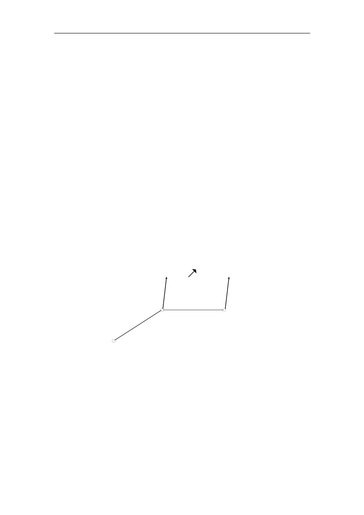
to several tool offset number. As it is shown in Figure7.5, if there is compensation on
axis X and Z at the tool path relative to the programming path (compensation vector is
composed of the compensation on axis X and Z), the end point of tool path is the
position of end point of program plus or minus the compensation (compensation
vector) assigned by T code.
Compensation path
Compensation vector
(composed of the amount of
axis-X and axis-Z)
Programming path
Program with T code
Figure 7.5 Tool wear-out compensation
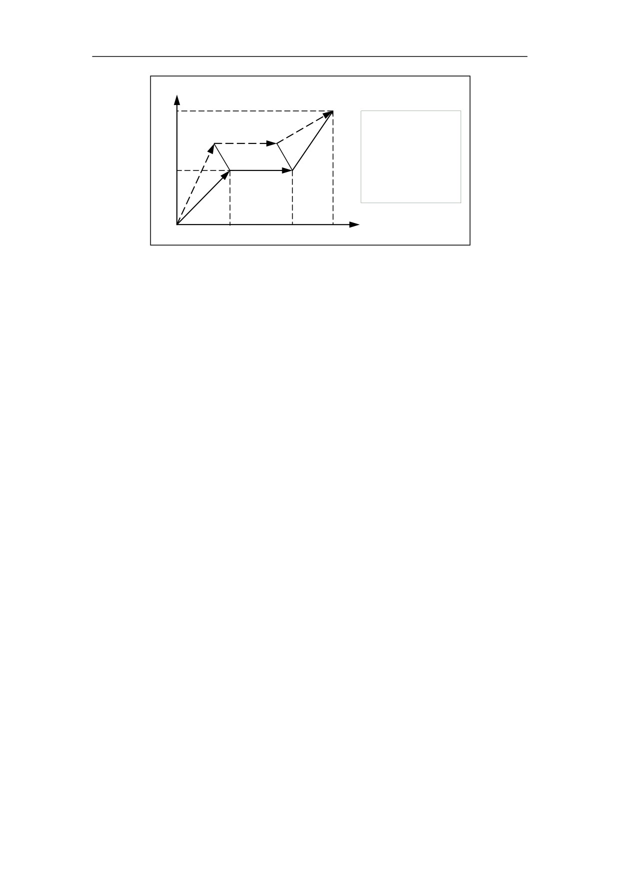
Example
As it is shown in the following figure, set the tool wear-out compensation, and then
cancel it.
88
7. Tool Function
X
100
T0202
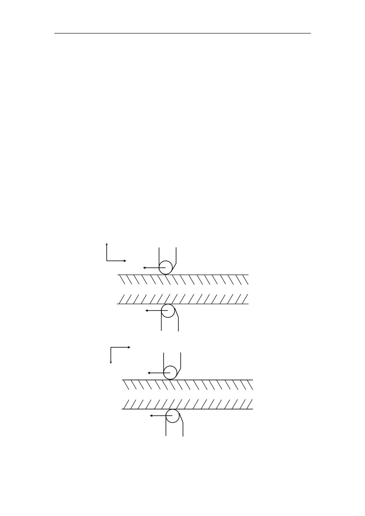
Compensation route
G01 X50 Z100
Z200
50
X100 Z250 T0200
Programming route
M30
Z
100
200
250
89
7. Tool Function
7.2 Tool Radius Compensation (G40, G41, G42)
Programming
G40
G00
G41
X_ Z_
G01
G
42
Explanation of the parameters
Tool nose radius compensation is specifies by G41, G42 and G40 or tool nose radius
compensation number specified by T code to add or cancel radius compensation.
G40 Tool nose radius compensation cancels
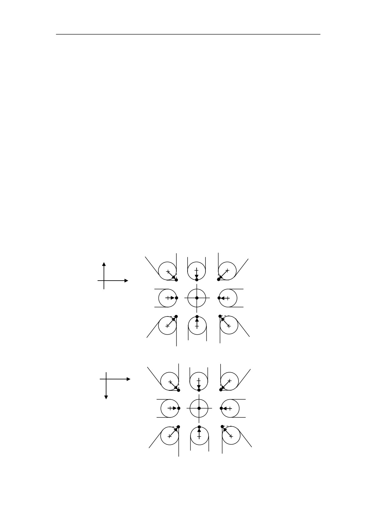
G41 Left cutter compensation (on the left of tool move direction) (Figure 7.6).
G42 Right cutter compensation (on the right of tool move direction) (Figure 7.6).
X, Z
Coordinate values of the end point. It is the point where the tool radius
compensation is activated or deactivated.
Note: G40, G41 and G42 are modal G-code.
Z
X
G42 On the right of tool
move direction
G41 On the left of tool
move direction
Z
G41 On the right of tool
move direction
X
G42 On the left of tool
move direction
Figure 7.6 Tool Radius Compensation
90
7. Tool Function
Function
NC program is generally aimed at cutting tool on a point at which the cutter location,
according to the contour of the workpiece size preparation. Turning tool cutter locus
ideal state of is the imagined cutter-tip A or arc center point O. Actually, tool nose is an
arc rather than a point. When the tool moves along an arc, it causes an error which
can be cancelled by tool nose radius compensation.
Note:
1) When G41/G42 without parameters, the compensation number representing
the tool nose radius compensation is assigned by T code. This corresponds
to the tool offset number.
2) G40, G41, and G42 must be used with G00 or G01. G02 or G03 cannot be
used.
In the register of tool radius compensation, it defines the direction of tool nose and
tool radius. The direction number of turning tool nose gives an identity of the position
relationship between CL point and tool nose circle center. There are 10 directions
from 0 to 9.
X
4
8
3
Z
0
9
5
7
1
6
2
● CL point A,+ Tool nose circle center O
1
6
2
Z
X
0
9
7
5
4
8
3
● CL point A,+ Tool nose circle center O
Figure 7.7 Position code of Tool Nose
91
7. Tool Function
Example
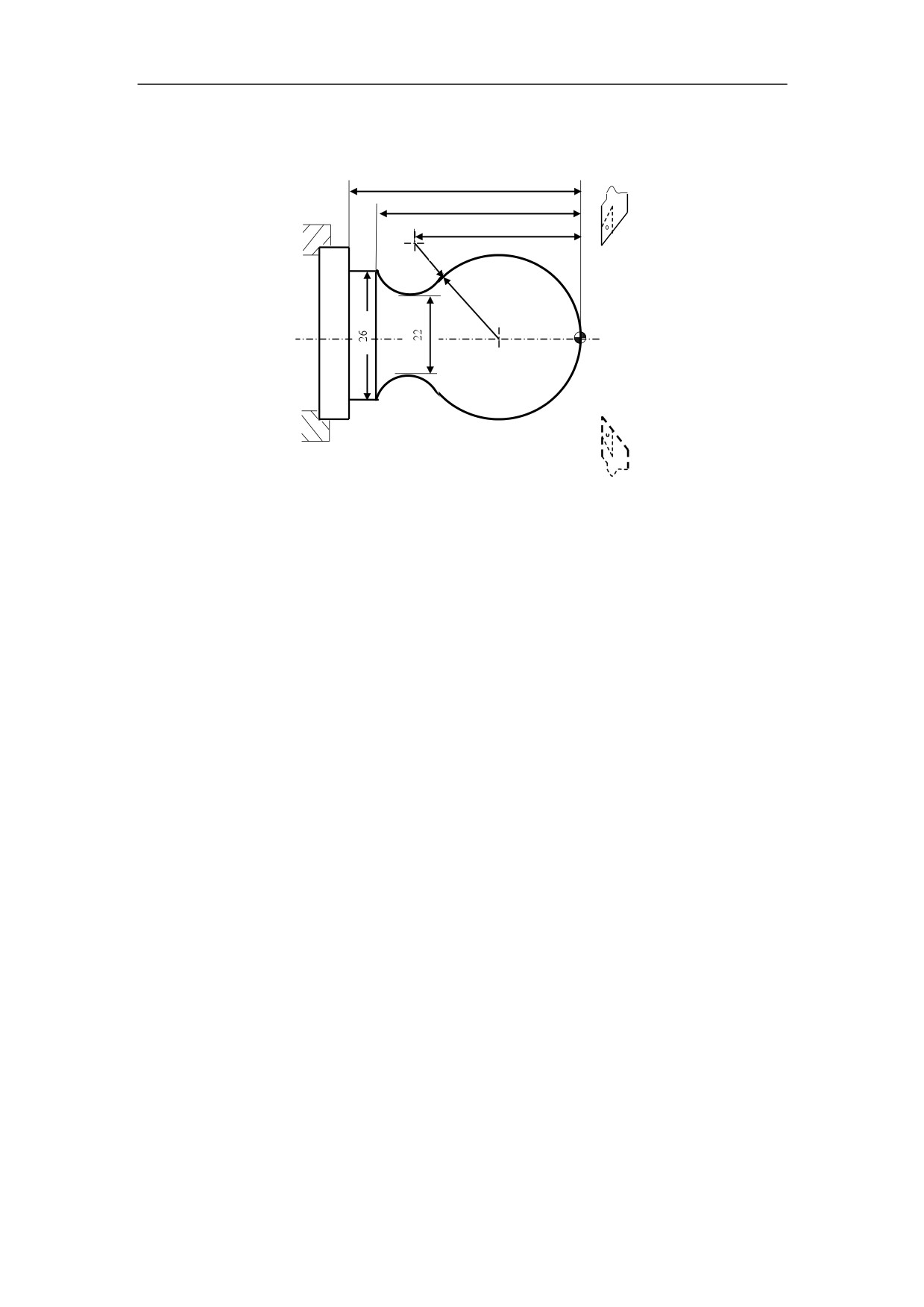
Use the tool radius compensation, and program for the part shown in Figure 7.2
40
31
27
R15
Figure 7.8 Tool Radius Compensation
%3323
N1 T0101
(Change NO.1knife to define its coordinate)
N2 M03 S400
(Spindle:400r/min CW)
N3 G00 X40 Z5
(To the position of program start)
N4 G00 X0
(The tool moves to workpiece center)
N5 G01 G42 Z0 F60
(Add tool radius compensation, and be close to workpiece)
N6 G03 U24 W-24 R15
(Machine R15 circular block)
N7 G02 X26 Z-31 R5
(Machine R5 circular block)
N8 G01 Z-40
(MachineΦ26 excircle)
N9 G00 X30
(Withdraw from the machined surface)
N10 G40 X40 Z5
(Cancel radius compensation, and return to the program start)
N11 M30
(Spindle stop, the main program end and reset)
92

8. Miscellaneous Function
8 Miscellaneous Function
As it is mentioned in Chapter 1.8, there are two ways of execution when a move
command and M code are specified in the same block.
1) Pre-M function
M command is executed before the completion of move command.
2) Post-M function
M command is executed after the completion of move command
There are two types of M code: one-shot M code, and modal M code.
Table 8-1 Type of M code
Type
Meaning
One-shot M code
The M code is only effective in the block in which it is specified
Modal M code
The M code is effective until another M code is specified.
93

8. Miscellaneous Function
8.1 M code List
The following is a list of M command.
Table 8-2 M code List
CNC
Pre/Post-M
Type of Mode
Function
M-function
function
M00
One-shot
Program stop
Post-M function
M01
One-shot
Optional stop
Post-M function
M02
One-shot
End of program
Post-M function
End of program with return
to
M30
One-shot
Post-M function
the beginning of program
M98
One-shot
Calling of subprogram
Post-M function
M99
One-shot
End of subprogram
Post-M function
PLC
Pre/Post-M
Type of Mode
Function
M-function
function
M03
Modal
Spindle forward rotation
Pre-M function
M04
Modal
Spindle reverse rotation
Pre-M function
M05
Modal
◣Spindle stop
Post-M function
M07
Modal
Number1 Coolant on
Pre-M function
M08
Modal
Number2 Coolant on
Pre-M function
M09
Modal
◣Coolant off
Post-M function
◣: default setting
94

8. Miscellaneous Function
8.2 CNC M-Function
8.2.1 Program Stop (M00)
M00 is one-shot M function, and it is post-M function.
The program can be stopped, so that the operator could measure the tool and the part,
adjust part and change speed manually, and so on.
When the program is stopped, the spindle is stopped and the coolant is off. All of the
current modal information remains unchanged. Resuming program could be executed
by pushing “Cycle Run” button on the machine control panel.
8.2.2 Optional Stop (M01)
M01 is one-shot M function, and it is post-M function.
Similarly to M00, M01 can also stop the program. All of the modal information is
maintained. The difference between M00 and M01 is that the operator must press
M01 button (
) on the machine control panel. Otherwise, the program would not be
stopped even if there is M01 code in the program.
8.2.3 End of Program (M02)
M02 is one-shot M function, and it is post-M function.
When M02 is executed, spindle, feed and coolant are all stopped. It is usually at the
end of the last program block. To restart the program, press “Cycle Run” button on the
operational panel.
8.2.4 End of Program with return to the beginning of program
(M30)
M30 is one-shot M function, and it is post-M function.
Similarly to M02, M30 can also stop the program. The difference is that M30 returns
control to the beginning of program. To restart the program, press “Cycle Run” button
on the operational panel.
8.2.5 Counting (M64)
The system can calculate the number of machining workpiece at the end of program
with M30. It can also calculate the accumulation of machining workpiece by executing
M64. It is required to set the parameter->machine parameters->the judgment of
95
8. Miscellaneous Function
counting the workpiece (0: M30, 1:M64).
8.2.6 User-defined Input and Output (M90, M91)
CNC system provides M90 (user-defined input) and system variable #1190 to control
the execution of G-code, according to PLC execution. It also provides M91
(user-defined output) and system variable #1190 to control PLC execution by the
G-code execution. Those two commands are related to PLC running condition, and
must be used with PLC.
Example 1: When PLC input signal X0.4 is valid (high level), one part of program is
executed. Otherwise, the other part of program is executed.
The code should be added in the function PLC1 of PLC program:
If(bit(X[0],4))
*ch_user_in(0)=1;
//it can be set to any values if necessary, i.e. #1190=1
else
*ch_user_in(0)=0;
//#1190=0
The example of G-code is as followed:
…
…
M90
//user-defined input, system would get the value of #1190 according to
PLC execution
If
#1190 EQ
1
//if PLC input signal X0.4 is valid, this part of program is run
…
…
else
//if PLC input signal X0.4 is not valid, this part of program is run
…
…
endif
Example 2: If the first part of G-code is executed, PLC output signal Y0.4 is valid
(high level). If the second part of G-code is executed, PLC output signal Y0.4 is not
valid (low level).
The example of G-code is as followed:
96

8. Miscellaneous Function
If
…
…
#1191=1
//the first part of program, it can be set to any values if necessary
else
…
…
#1191=0
//the second part of program, it can be set to any values
endif
M91
//user-defined output, the value of #1191 is assigned to *ch_user_out(0)
The code should be added in the function PLC1 of PLC program:
If(*ch_user_out(0)==1)
//if the first part of program is run
Y[0]|=0x10;
//Y0.4=1, output signal Y0.4 is valid (high level)
else
Y[0]&=~0x10;
//if the second part of program is run, Y0.4=0
8.2.7 Saving Macro (M94)
M94 is to save macro (#1300~#1399) to the files.
8.2.8 Subprogram Control (M98, M99)
z Calling a Subprogram (M98)
M98 P_ L_
P program number of the subprogram
L repeated times of subprogram
P ○○○○ L □□□□
Times of subprogram calling (1-9999)
It can be ignored, if the times is once.
Program number of subprogram (0000-9999)
If the times of calling is not input, the prefix “%”
of subprogram number can be omitted.
When inputing the times of calling, the digits of
subprogram must be four.
In Auto mode, CNC would call the subprogram specified by the parameter P after the
rest of code of program is run, when M98 is executed. The maximum times of
subprogram calling is 9999. M98 is not valid in MDI mode.
97
8. Miscellaneous Function
Note: Calling subprogram can be used with parameters. Blank space is not
allowed at the beginning of the subprogram.
z End of Subprogram (M99)
M99 indicates the end of subprogram and returns control to the main program. It is not
valid in MDI mode.
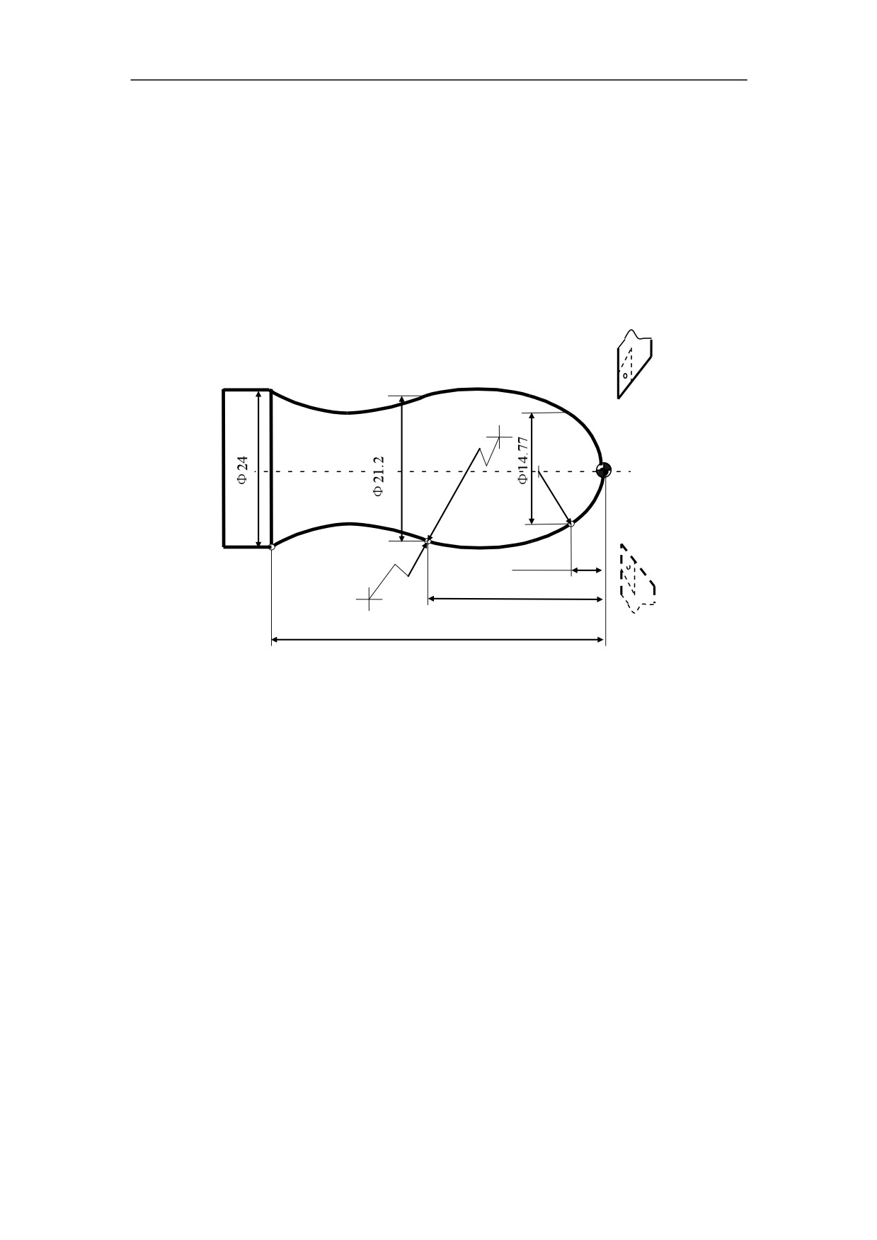
Example
R60
R8
4.923
R40
44.8
73.436
Figure 8.1 Subprogram Control - Example
%3111
(main program name)
N1 T0101
(Tool No.1)
N2 G92 X32 Z1
(coordinates setting, the position of aligning tool)
N3 G00 Z0 M03 S46
(move to the start of subprogram, spindle CW)
N4 M98 P0003 L5
(subprogram call, repeated times: 5)
N5 G36 G00 X32 Z1
(return to the position of aligning tool)
N6 M05
(spindle stop)
N7 M30
(main program ends and resets)
%0003
(subprogram name)
N1 G37 G01 U-12 F100
(radius programming, move to the start of cutting)
N2 G03 U7.385 W-4.923 R8
(R8 arc)
N3 U3.215 W-39.877 R60
(R60 arc)
N4 G02 U1.4 W-28.636 R40
(R40 arc)
N5 G00 U4
(leave the cutting surface)
N6 W73.436
(return to the beginning of cycle of axis-Z)
N7 G01 U-5 F100
(set the cutting amount of cycles)
N8 M99
(subprogram ends, return to the main program)
98
8. Miscellaneous Function
8.3 PLC M Function
8.3.1 Spindle Control (M03, M04, M05)
M03 starts spindle to rotate CW at the set speed set in the program.
M04 starts spindle to rotate CCW at the set speed in the program.
M05 stops spindle.
M03, M04 are modal M code, and they are pre-M function. M05 is modal M code, and
it is post-M function. M05 is the default setting.
8.3.2 Coolant Control (M07, M08, M09)
M07, M08 can turn on the coolant.
M09 can turn off the coolant.
M07 and M08 are modal M code, and they are pre-M function. M09 is one-shot M
code, and it is post-M function. Moreover, M09 is the default setting.
99
9 Functions to Simplify Programming
This chapter would introduce:
1) Canned Cycle
Internal diameter/ Outer diameter cutting cycle (G80)
End face turning cycle (G81)
Thread cutting cycle (G82)
End face peck drilling cycle (G74)
Outer diameter grooving cycle (G75)
2) Multiple Repetitive Cycle
Stock Removal in Turning (G71)
Stock Removal in Facing (G72)
Pattern Repeating (G73)
Multiple Thread Cutting Cycle (G76)
100
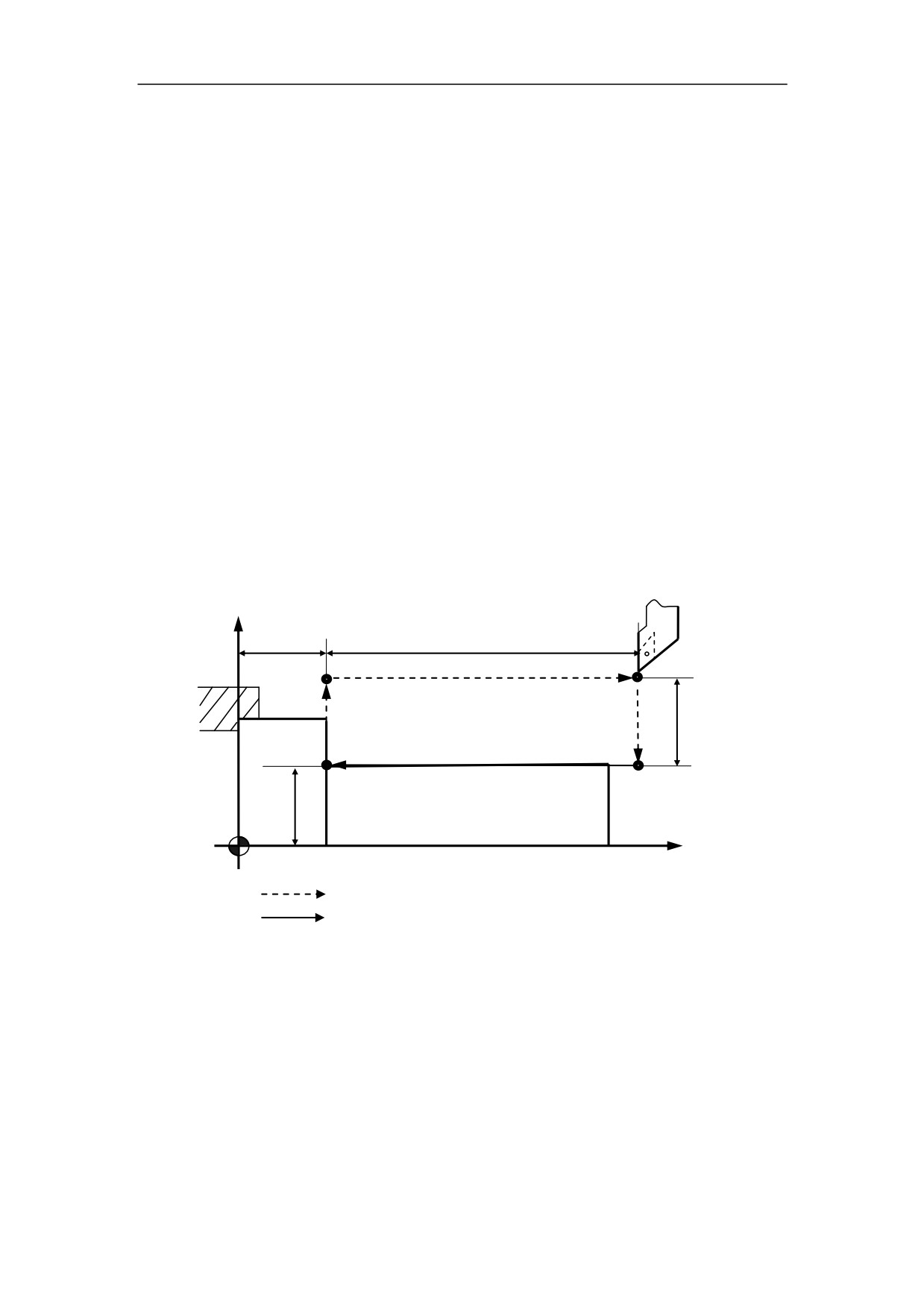
9.1 Canned Cycles
To simplify programming, the canned cycle command can execute the specific
operation using one G code, instead of several separated G commands in the
program.
9.1.1 Internal Diameter/Outer Diameter Cutting Cycle (G80)
z Straight Cutting Cycle
Programming
G80 X(U)_ Z(W)_ F_
Explanation of the parameters
X, Z
Coordinate values of end point (point C) in absolute command
U, W Coordinate values of end point (point C) with reference to the initial point
(point A) in incremental command
F
Feedrate
+X
z
w
D
4R
A
3R
1R
u/2
2F
C
B
x/2
+Z
A: Initial point
Rapid traverse speed
B: Starting point of cutting
Feedrate
C: End point of cutting
D: Retraction point
Figure 9.1 Straight cutting cycle (G80)
Function
This command can implement the straight cutting. The machining
path
is
A→B→C→D→A.
101
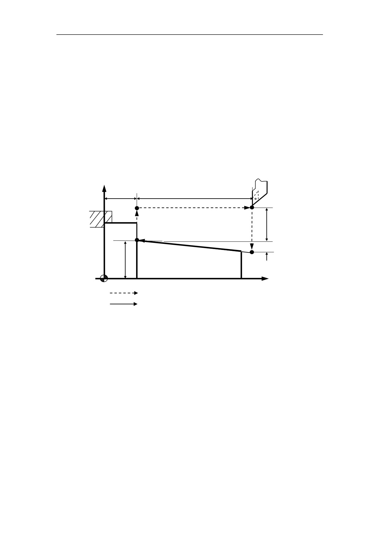
z Taper Cutting Cycle
Programming
G80 X(U)_ Z(W)_ I_ F_
Explanation of the parameters
X, Z
Coordinate values of end point (point C) in absolute command
U, W Coordinate values of end point (point C) with reference to the initial point
(point A) in incremental command
I
The radius difference between starting point B and end point C. It is negative,
if the radius of point B is less than the radius of point C. Otherwise, it is positive.
F
Feedrate
+X
z
w
D
4R
A
3R
1R
u/2
C
2F
i
x/2
B
+Z
Rapid traverse speed
A: Initial point
B: Starting point of cutting
Feedrate
C: End point of cutting
D: Retraction point
Figure 9.2 Taper Cutting Cycle (G80)
Function
This command can implement the taper cutting. The machining
path
is
A→B→C→D→A.
102
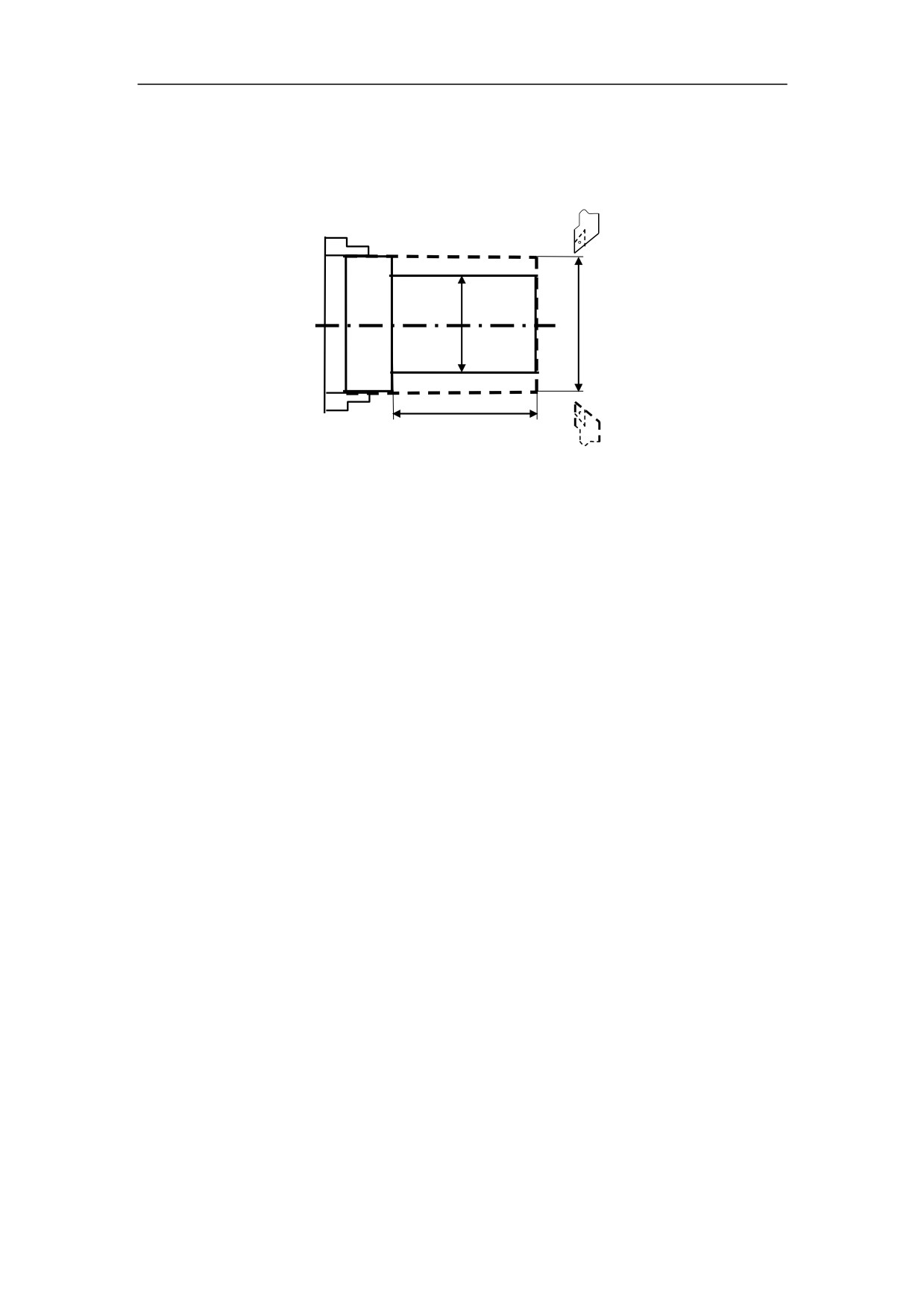
Example 1
Use G80 command to machine the cylindrical part in two steps - rough machining and
finish machining.
30
35
50
Figure 9.3 Internal Diameter/Outer Diameter Cutting Cycle - Example 1
%3320
N1 T0101
N2 M03 S460
N3 G00 X90Z20
N4 X40 Z3
N5 G80 X31 Z-50 F100
N6 G80 X30 Z-50 F80
N7 G00X90 Z20
N8 M30
103
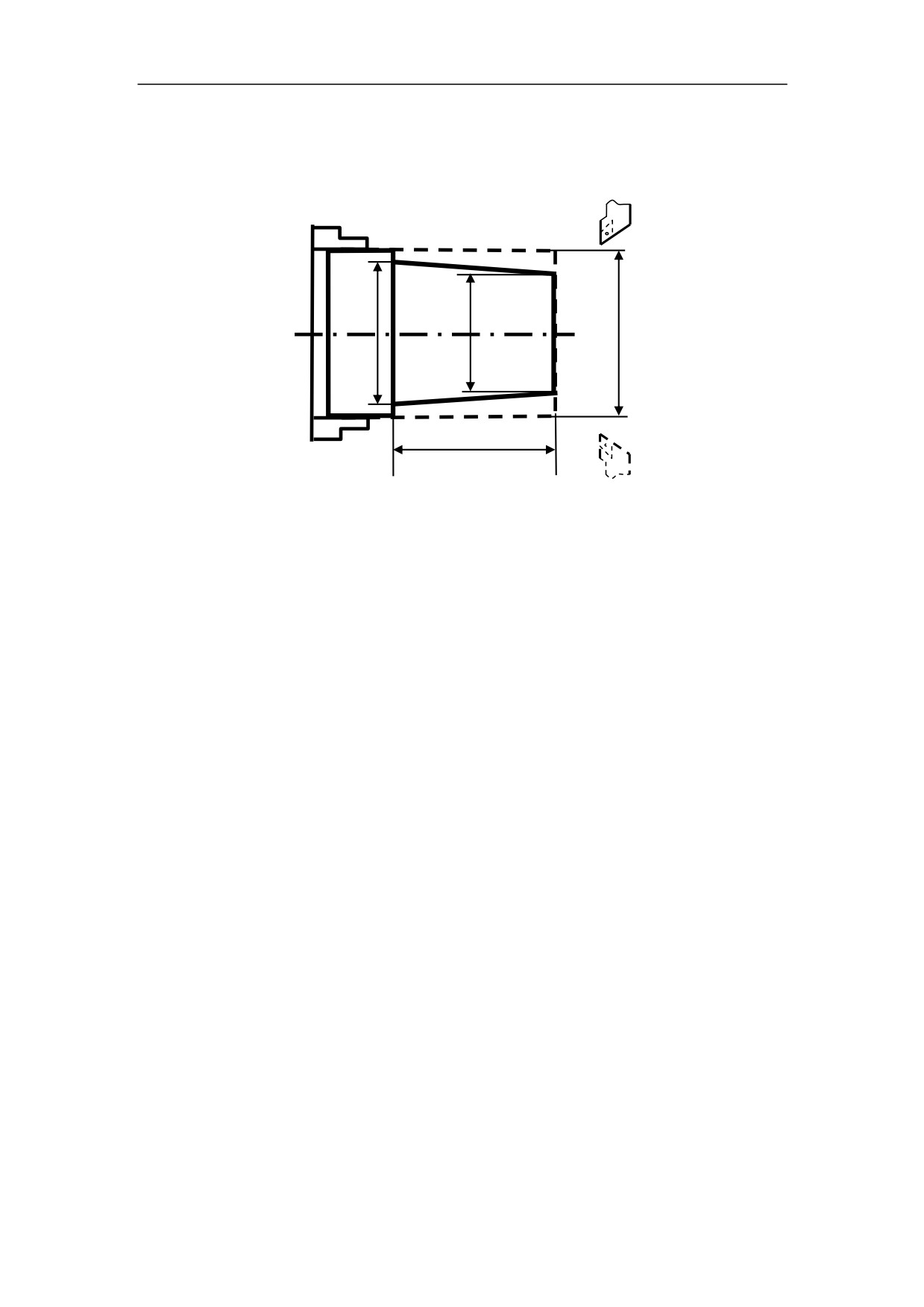
Example 2
Use G80 command to machine the tapered part in two steps - rough machining and
finish machining.
50
Figure 9.4 Internal Diameter/Outer Diameter Cutting Cycle - Example 2
%3321
N1 T0101
N2 G00 X100Z40 M03 S460
N3 G00 X40 Z5
N4 G80 X31 Z-50 I-2.2 F100
N5 G00 X100 Z40
N6 T0202
N7 G00 X40 Z5
N8 G80 X30 Z-50 I-2.2 F80
N9 G00 X100 Z40
N10 M05
N11 M30
104
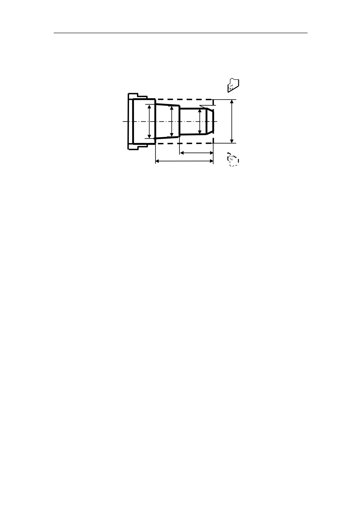
Example 3
Use G80 command to machine the tapered part in two steps - rough machining and
finish machining.
2×45°
30
28
24
35
20
50
Figure 9.5 Internal Diameter/Outer Diameter Cutting Cycle - Example 3
%3322
N1 T0101
N2 M03 S460
N3 G00 X100 Z40
N4 X40 Z3
N5 G80 X31 Z-50 F100
N6 G80 X25 Z-20
N7 G80 X29 Z-4 I-7 F100
N8 G00 X100 Z40
N9 T0202
N10 G00 X100 Z40
N11 G00 X14 Z3
N12 G01 X24 Z-2 F80
N13 Z-20
N14 X28
N15 X30 Z-50
N16 G00 X36
N17 X80 Z10
N18 M05
N19 M30
105
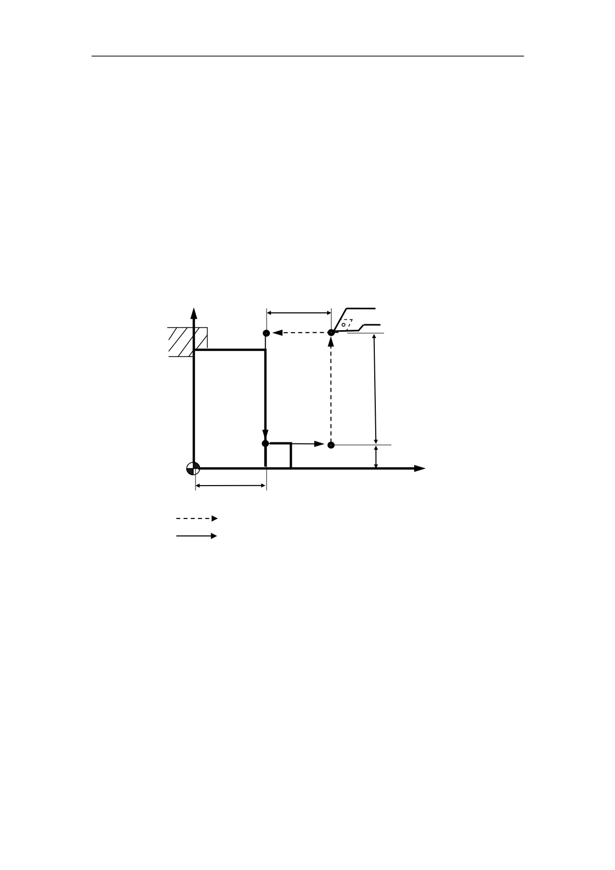
9.1.2 End Face Turning Cycle (G81)
z Face Cutting Cycle
Programming
G81 X(U)_ Z(W)_ F_
Explanation of the parameters
X, Z
Coordinate values of end point (point C) in absolute command
U, W Coordinate values of end point (point C) with reference to the initial point
(point A) in incremental command
F
Feedrate
w
+X
B
1R
A
2F
4R
u/2
3F
D
C
x/2
+Z
z
Rapid traverse speed
A: Initial point
B: Starting point of cutting
Feedrate
C: End point of cutting
D: Retraction point
Figure 9.6 Face Cutting Cycle (G81)
Function
This command can implement the end face cutting. The machining path is
A→B→C→D→A.
106
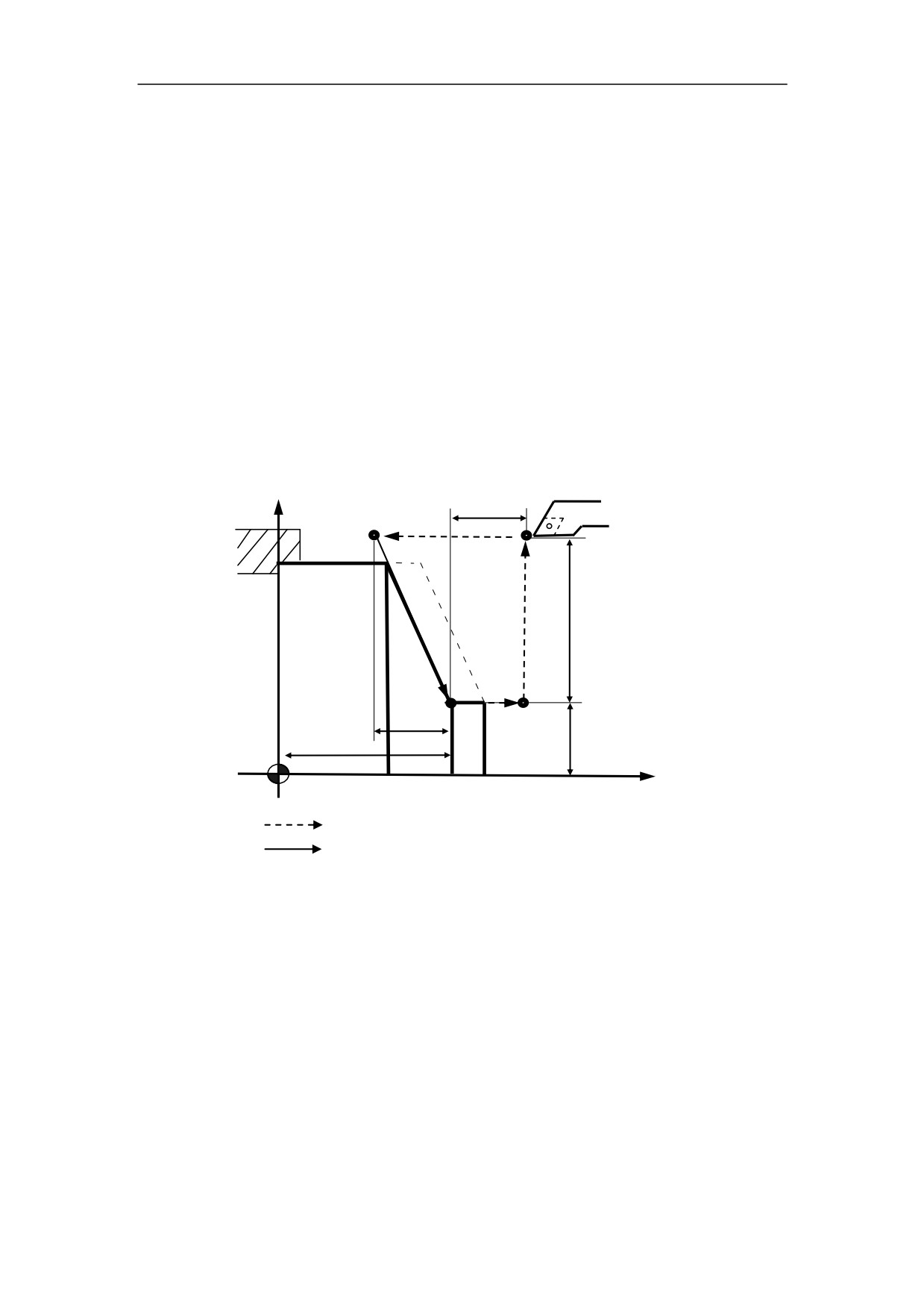
z Taper Face Cutting Cycle
Programming
G81 X(U)_ Z(W)_ K_ F_
Explanation of the parameters
X, Z
Coordinate values of end point (point C) in absolute command
U, W Coordinate values of end point (point C) with reference to the initial point
(point A) in incremental command
K
The distance on Z axis of the starting point (point B) with reference to the end
point (point C). It is negative, if the value of point C on Z axis is more than point B’s. It
is positive, if the value of point C on Z axis is less than point B’s.
F
Feedrate
+X
w
B
1R
A
2F
4R
u/2
3F
C
D
k
x/2
z
+Z
A: Initial point
Rapid traverse speed
B: Starting point of cutting
Feedrate
C: End point of cutting
D: Retraction point
Figure 9.7 Taper Face Cutting Cycle (G81)
Function
This command can implement the taper face cutting. The machining path is
A→B→C→D→A.
107
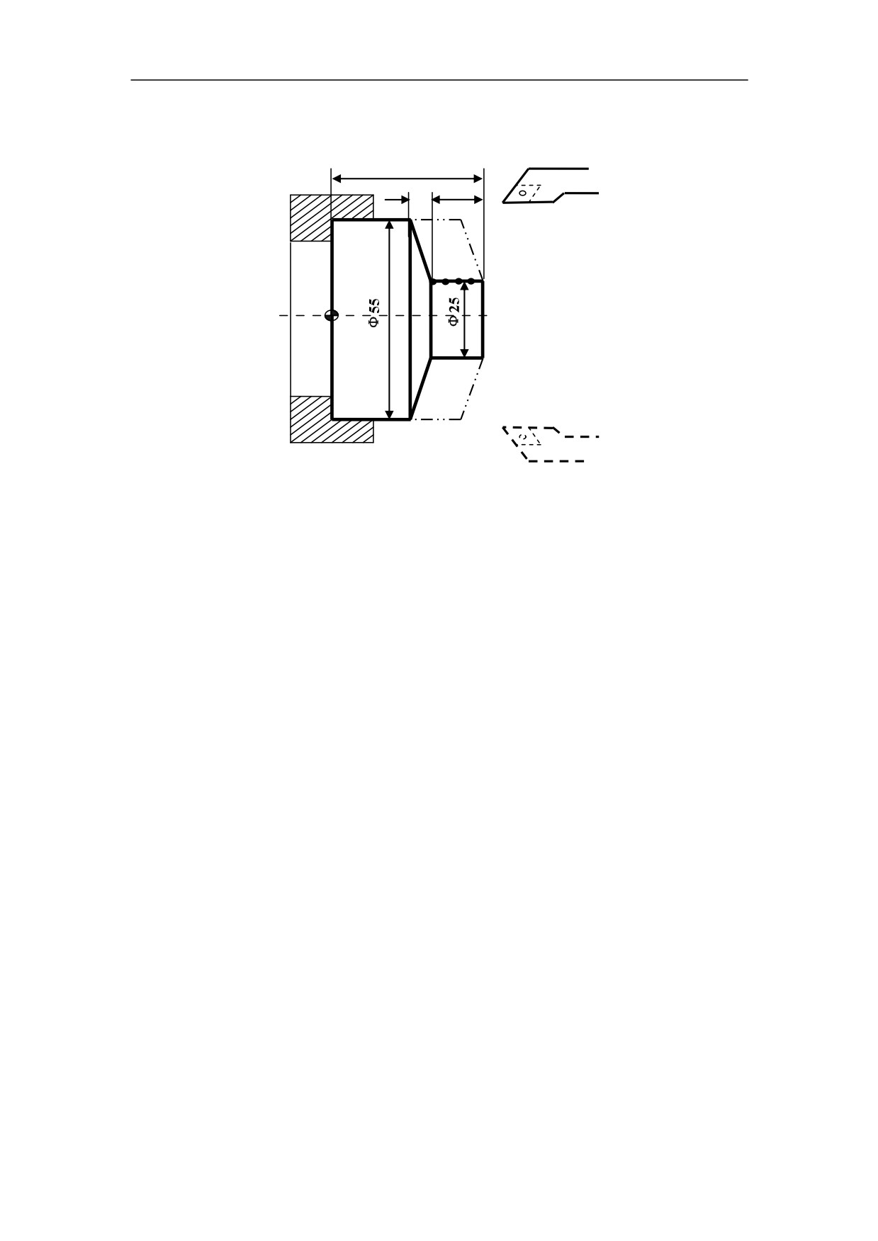
Example
Use G81 to program. The dashed line stands for the roughcast.
33.5
3
8
Figure 9.8 End Face Turning Cycle (G81)
%3323
N1 T0101
N2 G00 X60 Z45
N3 M03 S460
N4 G81 X25 Z31.5 K-3.5 F100
N5 X25 Z29.5 K-3.5
N6 X25 Z27.5 K-3.5
N7 X25 Z25.5 K-3.5
N8 M05
N9 M30
108
9.1.3 Thread Cutting Cycle (G82)
z Cylindrical Thread Cutting Cycle
Programming
G82 X(U)_ Z(W)_ R_ E_ C_ P_ F/J_Q_
Explanation of the parameters
X, Z
Coordinate values of end point (point C) in absolute command
U, W Coordinate values of end point (point C) with reference to the initial point
(point A) in incremental command.
R, E Retraction amount of thread cutting. R and E are vectors. R is the retraction
of axis-Z, and E is the retraction of axis-X. R and E can be omitted, and it means that
the retraction function is not required.
C
The number of thread head. It is single thread when C is 0 or 1.
P
Uni-tip thread cutting, it is the spindle turning corner of spindle pulse to start
(defaule is 0). Muti-tip thread cutting, it is the spindle turning corner of start points.
F
Thread lead per revolution
J
Thread lead in inch measurement
Q
1) Acceleration constant of thread cutting retraction. When it is set to zero, the
acceleartion is maximum. The more this value is, the acceleration time is longer,
and the retraction is longer. Q must be set to zero or more than zero.
2) When there is no Q, the set acceleration constant on each axis is used in the
retraction.
3) R and E must be set when the retraction function is required.
4) The retraction ratio of minor axis:major axis should not be more than “20“.
5) Q is one-shot G code.
109
+X
z
w
D
4R
A
3R
u/2
1R
e
2F
C
B
r
x/2
+Z
L
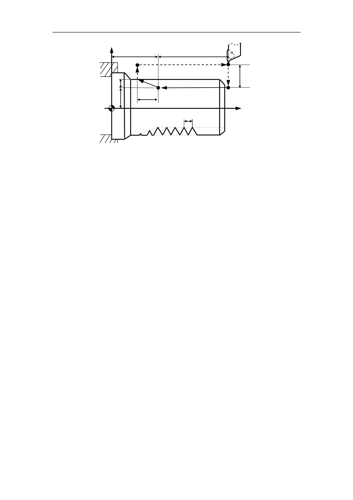
Figure 9.9 Cylindrical Thread Cutting Cycle (G82)
Function
This command can implement the cylindrical thread cutting. The machining path is
A→B→C→D→E→A.
Note
This command is same as G32 (Thread cutting with constant lead). This cycle would
stop after the whole action is done in the state of feed hold.
z Taper Thread Cutting Cycle
Programming
G82 X(U)_ Z(W)_ I_ R_ E_ C_ P_ F(J)_ Q_
Explanation of the parameters
X, Z
Coordinate values of end point (point C) in absolute command
U, W Coordinate values of end point (point C) with reference to the initial point
(point A) in incremental command
I
The radius difference between starting point B and end point C. It is negative,
if the radius of point B is less than the radius of point C. Otherwise, it is positive.
R, E Retraction amount of thread cutting. R and E are vectors. R is the retraction
of axis-Z, and E is the retraction of axis-X. R and E can be omitted, and it means that
the retraction function is not required.
C
The number of thread head. It is single thread when C is 0 or 1.
P
Uni-tip thread cutting, it is the spindle turning corner of spindle pulse to start
(defaule is 0). Muti-tip thread cutting, it is the spindle turning corner of start points.
F
Thread lead per revolution
J
Thread lead in inch measurement
110
Q
1)
Acceleration constant of thread cutting retraction. When it is set to zero, the
acceleartion is maximum. The more this value is, the acceleration time is longer,
and the retraction is longer. Q must be set to zero or more than zero.
2)
When there is no Q, the set acceleration constant on each axis is used in the
retraction.
3)
R and E must be set when the retraction function is required.
4)
The retraction ratio of minor axis:major axis should not be more than “20“.
5)
Q is one-shot G code.
+X
z
w
D
4R
A
3R
u/2
1R
e
i
C
2F
x/2
r
B
+Z
L
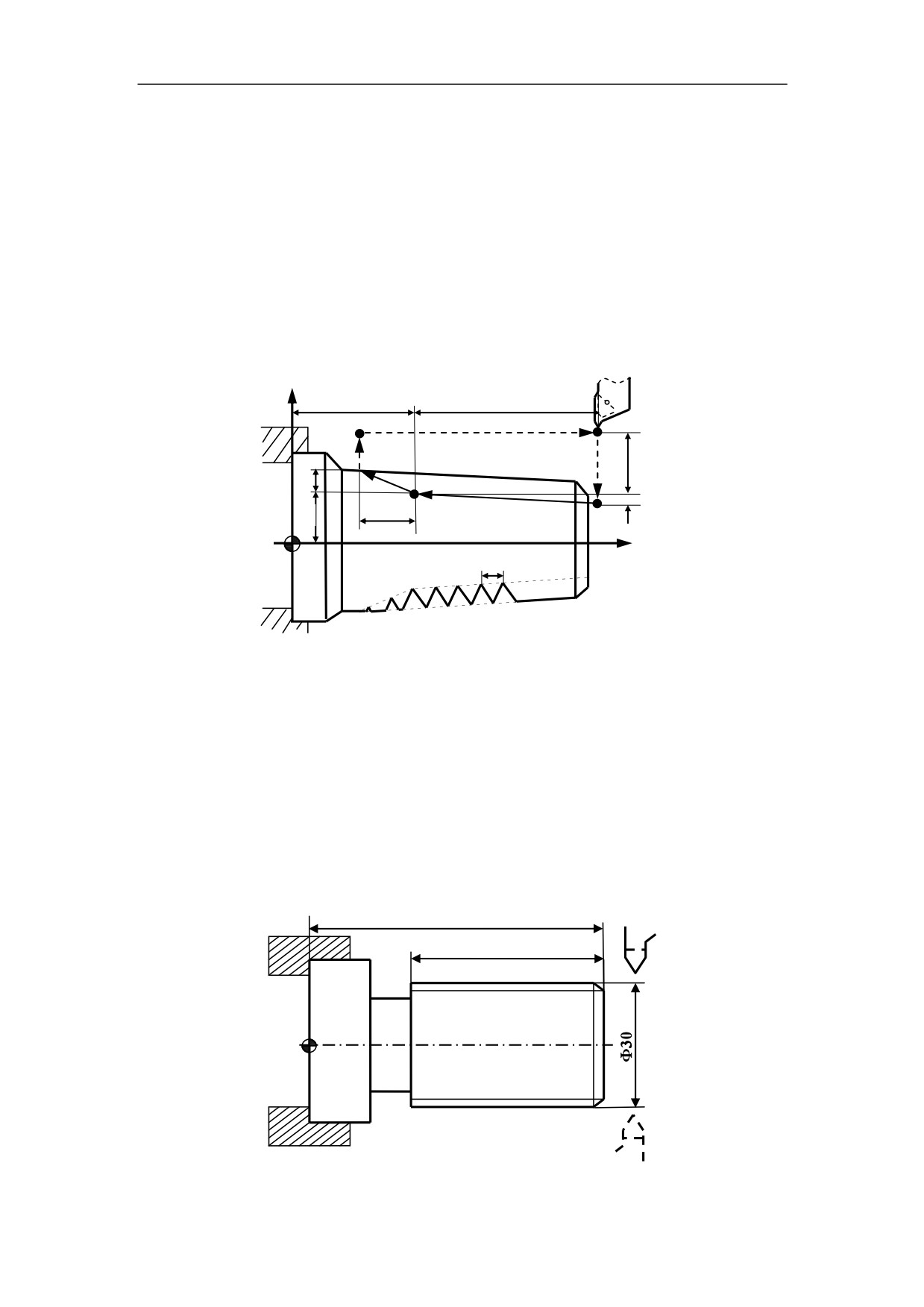
Figure 9.10 Taper Thread Cutting Cycle (G82)
Function
This command can implement the taper thread cutting. The machining path is
A→B→C→D→A.
Example
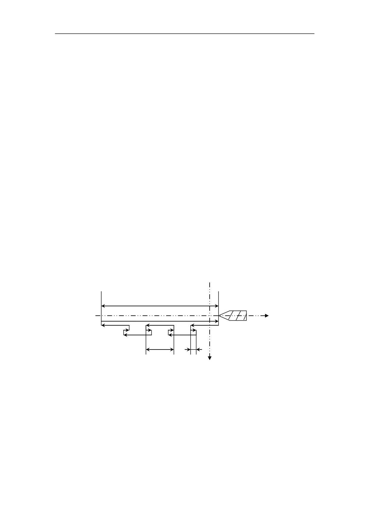
Use G82 command to program. The screw’s pitch is 1.5, and the number of thread
head is 2.
1
80
Figure 9.11 Thread Cutting Cycle - Example
111
%3324
N1 G54 G00 X35 Z104
(Choose coordiante system G54, to cycle start)
N2 M03 S300
(Spindle CW 300r/min)
N3 G82 X29.2 Z18.5 C2 P180 F3 (1st thread cutting cycle,Depth 0.8mm)
N4 X28.6 Z18.5 C2 P180 F3
(2nd thread cutting cycle, Depth 0.4mm)
N5 X28.2 Z18.5 C2 P180 F3
(3rd thread cutting cycle, Depth 0.4mm)
N6 X28.04 Z18.5 C2 P180 F3
(4th thread cutting cycle, Depth 0.16mm)
N7 M30
(Spindle stop. Main system end and reset)
9.1.4 End Face Peck Drilling Cycle (G74)
Programming
G74 Z(W)_ R(e) Q(△ K) F_
Explanation of the parameters
Z
Coordinate value on Z axis of the end point in absolute command
W Coordinate value on Z axis of the end point with reference to the starting
point in incremental command
R
Retraction amount(e) for each feed. It must be absolute value.
Q
Depth of drilling(△ K) for each feed. It must be absolute value.
F
Feedrate
W
Z
△K
e
X
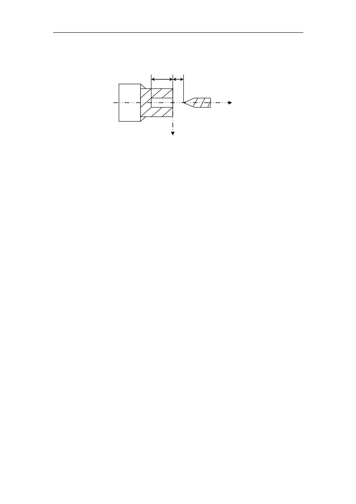
Figure 9.12 End Face Peck Drilling Cycle (G74)
Function
This command can drill a hole on end face.
112
Example
Use G74 to drill a hole on a workpiece.
60
10
Z
X
Figure 9.13 End Face Peck Drilling Cycle - Example
%1234
T0101
M03S500
G01 X0 Z10
G74 Z-60R1Q5F1000
M30
9.1.5 Outer Diameter Grooving Cycle (G75)
Programming
G75 X(U)_ R(e) Q(△ K) F_
Explanation of the parameters
X
Coordinate value on X axis of the end point in absolute command
U
Coordinate value on X axis of the end point with reference to the starting
point in incremental command
R
Retraction amount(e) for each feed. It must be absolute value.
Q
Depth of grooving(△ K) for each feed. It must be absolute value.
F
Feedrate
113
Z
△K
U/2
e
X
Figure 9.14 Outer Diameter Grooving Cycle (G75)
Function
This command can be used for grooving.
Example
Use G75 to groove a hole on a workpiece.
Φ80
Z
50
X
Figure 9.15 Outer Diameter Grooving Cycle - Example
%1234
T0101
M03S500
G01 X50 Z50
G75 X10R1Q5F1000
M30
114
9.2 Multiple Repetitive Cycle
Multiple repetitive cycle command can only use one command to finish the rough
machining and the finish machining.
Here are some notes for G71, G72 and G73:
1) Blocks, which is specified by address P, have preparatory function G00 or G01 in
01 group, or it will give an alarm;
2) In MDI, multiple repetitive cycle command is forbidden;
3) In multiple repetitive cycle G71,G72,G73, between blocks, whose sequence
numbers specified by P and Q, should not contain M98 subprogram call and M99
subprogram return command.
9.2.1 Stock Removal in Turning (G71)
z Stock Removal in Turning without Groove
Programming
G71 U(△ d) R(r) P(ns) Q(nf) X(△ x) Z(△ z) F(f) S(s) T(t)
Explanation of the parameters
U(△ d)
the cutting depth (radius designation). The cutting direction depends
on the direction of AA’.
R(r)
Retraction amount
P(ns)
Sequence number of the first block for the finishing program.
Q(nf)
Sequence number of the last block for the finishing program.
X(△ x)
Distance and direction of finishing allowance on X axis
Z(△ z)
Distance and direction of finishing allowance on Z axis
F(f), S(s), T(t)
F, S, T function are only effective for the rough machining, i.e, it is
not effective in the finishing program - between P(ns) and Q(nf).
115