Century Star Turning CNC System. Programming Guide (V3.5 April, 2015) - page 3
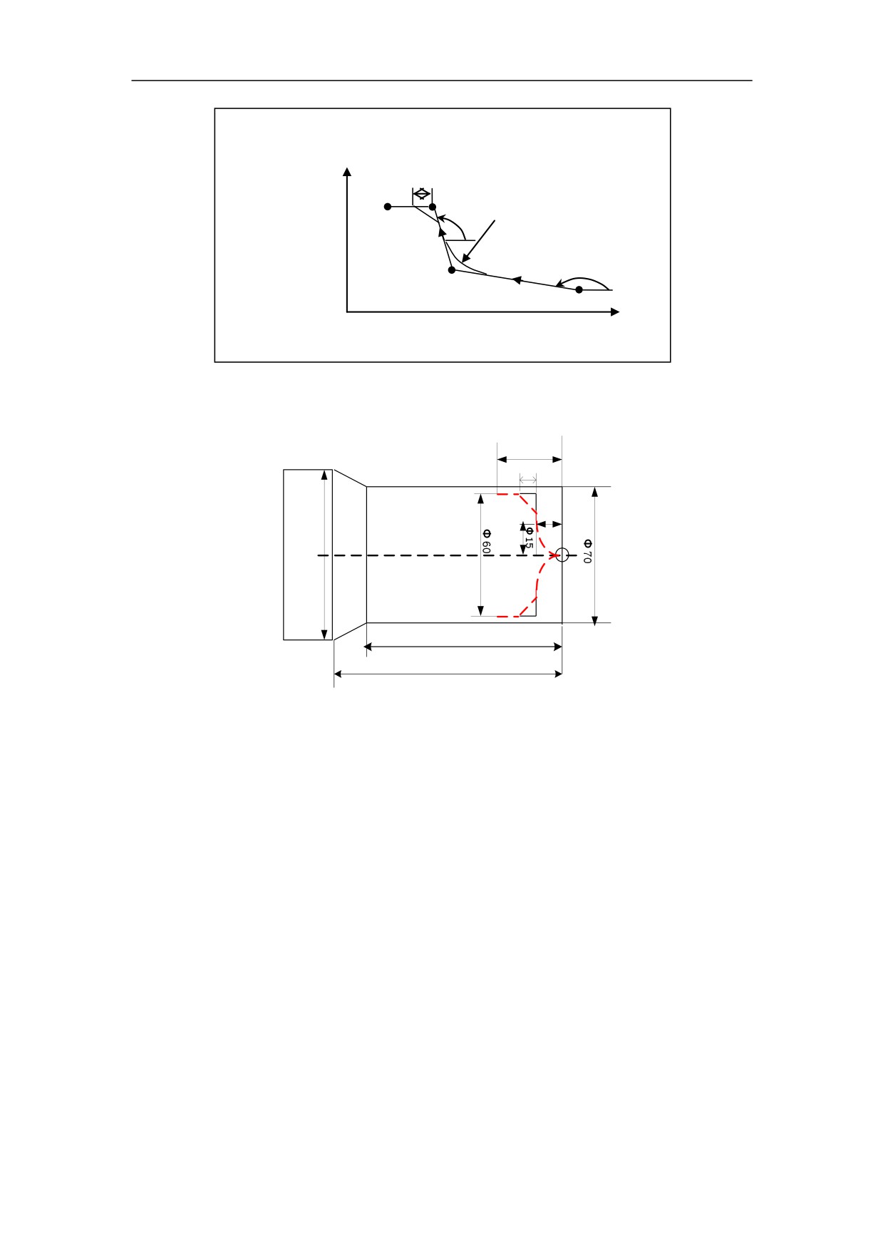
3. Interpolation Function
X2_Z2_R1_;
X
X3_Z3_C2_;
C2
X4_Z4_
(X3, Z3)
A2
R1
(X4, Z4)
A1
(X2, Z2)
Z
Example
Φ 40
C10
Φ 15
Φ 80
Φ 70
Φ 80
%3329
N1 T0101
N2 M03 S400
N3 G00 X100 Z40
N4 X0 Z0
N5 G01 X0 Z-15 R15
;rounding
N6 G01 X60 Z-15C10
;chamfering
N7 G01 X60 Z-40
N8 G00X100 Z40
N9 M30
56
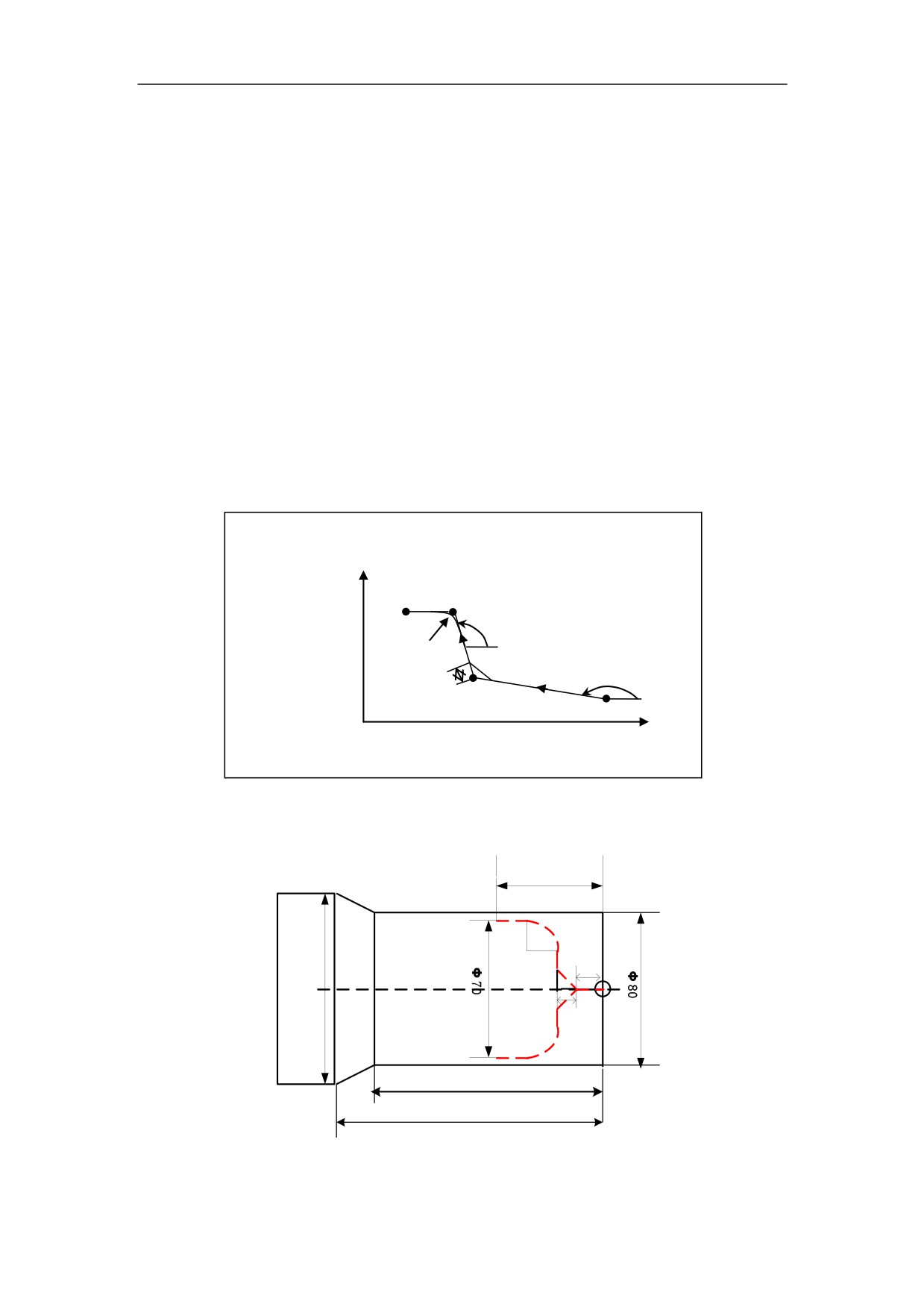
3. Interpolation Function
3.7.7 Chamfering then Rounding
Programming
G01 X_Z_C_
G01 X_Z_R_
G01 X_Z_
Explanation of the parameters
X_/Z_: Line location address;
R_: Rounding radius;
C_: Chamfer edge length;
Function
Round and Chamfering are inserted between two linear interpolation.
X
X2_Z2_C1_;
X3_Z3_R2_;
X4_Z4_
(X4, Z4)
(X3, Z3)
A2
R2
C1
A1
(X2, Z2)
Z
Example
Φ 50
R15
R15
Φ 10
Φ 90
C10
Φ 70
Φ 80
57
3. Interpolation Function
%3330
N1 T0101
N2 M03 S400
N3 G00 X100 Z40
N4 X0 Z0
N5 G01 X0 Z-20 C10
;Chamfering
N6 G01 X70 Z-20 R15
;Rounding
N7 G01 X70 Z-50
N8 G00 X100Z40
N8 M30
58
4. Feed Function
4 Feed Function
There are two kinds of feed functions:
1. Rapid Traverse
The tool is moved at the rapid traverse speed set in CNC.
2. Cutting Feed
The tool is moved at the programmed cutting feedrate.
Moreover, this chapter would introduce “Dwell”.
59
4. Feed Function
4.1 Rapid Traverse (G00)
Positioning command (G00) is to move the tool at the rapid traverse speed (the
highest possible speed).
This rapid traverse speed can be controlled by the machine control panel. For more
detailed information, please refer to turning operation manual.
60
4. Feed Function
4.2 Cutting Feed (G94, G95)
Programming
G94 [F_ ]
G95 [F_ ]
Explanation of the parameters
G94 feedrate per minute.
On linear axis, the unit of feedrate is mm/min, or in/min.
On rational axis, the unit of feedrate is degree/min.
G95 feedrate per revolution
The unit of feedrate is mm/rev, or in/rev.
Note:
1) G94 is the default setting
2) G95 is only used when there is spindle encoder.
Function
The feedrate can be set by G94 or G95.
61
4. Feed Function
4.3 Dwell (G04)
Programming
G04 P_
Explanation of the parameters
P dwell time (specified in seconds)
Function
It can be used to interrupt machining to get the smooth surface. It can be used to
control the groove cutting, drilling, and turning path.
62
5. Coordinate System
5 Coordinate System
This chapter would introduce:
1) Reference Position Return (G28)
2) Auto Return from Reference Position (G29)
3) Setting a Workpiece Coordinate System (G92)
4) Selecting a Machine Coordinat System (G53)
5) Selecting a Workpiece Coordinate System (G54~G59)
6) Origin of a Workpiece Coordinate System (G51, G50)
7) Absolute and Incremental Programming (G90, G91)
8) Diameter and Radius Programming (G36, G37)
9) Inch/Metric Conversion (G20, G21)
10) Changing Coordinate and Tool Offset (G10)
63
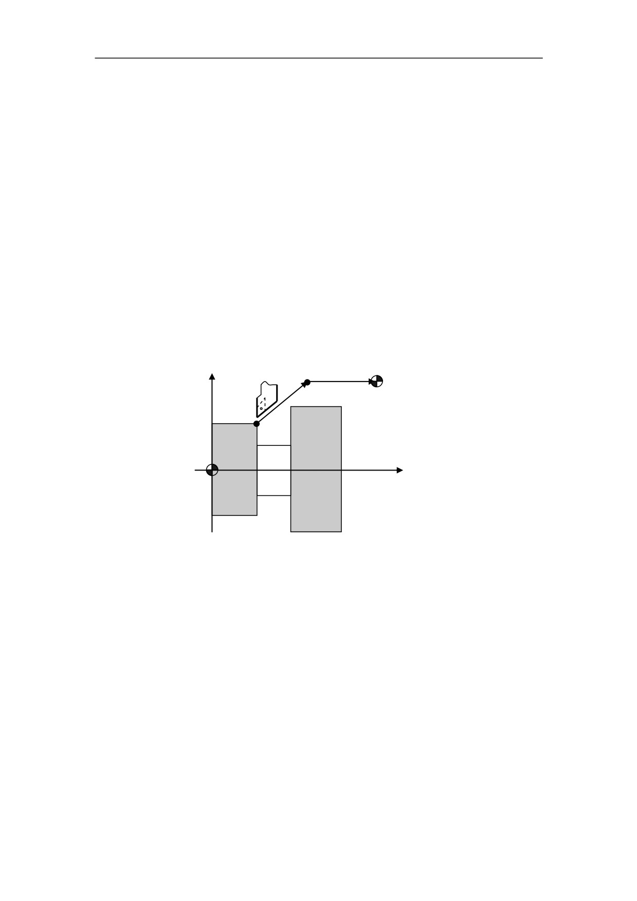
5. Coordinate System
5.1 Reference Position Return (G28)
Programming
G28 X(U)_ Z(W)_
Explanation of the parameters
X, Z
Coordinate values of the intermediate point in absolute command
U,W Coordinate values of the intermediate point with reference to the starting
point in incremental command
Function
The tool is moved to the intermediate point rapidly, and then returned to the reference
point.
X
Z
Figure 5.1 Reference Position Return
Note:
1) In general, G28 is used to change tools or cancel the mechanical error. Tool radius
compensation and tool length compensation should be cancelled when G28 is
executed.
2) G28 can not only make the tool move to the reference point, but also can save the
intermediate position to be used in G29.
3) When the power is on and manual reference position return is not available, G28 is
same as the maunaul reference position return. The direction of this reference
position return (G28) is set by the axis parameter - reference approach direction.
4) G28 is one-shot G code.
64
5. Coordinate System
5.2 Auto Return from Reference Position (G29)
Programming
G29 X(U)_ Z(W)_
Explanation of the parameters
X, Z
Coordinate value of the end point in absolute command
U, W Coordinate value of the end point in incremental command
Function
The tool is moved rapidly from the intermediate point defined in G28 to the end point.
Thus, G29 is generally used after G28 is defined.
Note:
G29 is one-shot G code.
65
5. Coordinate System
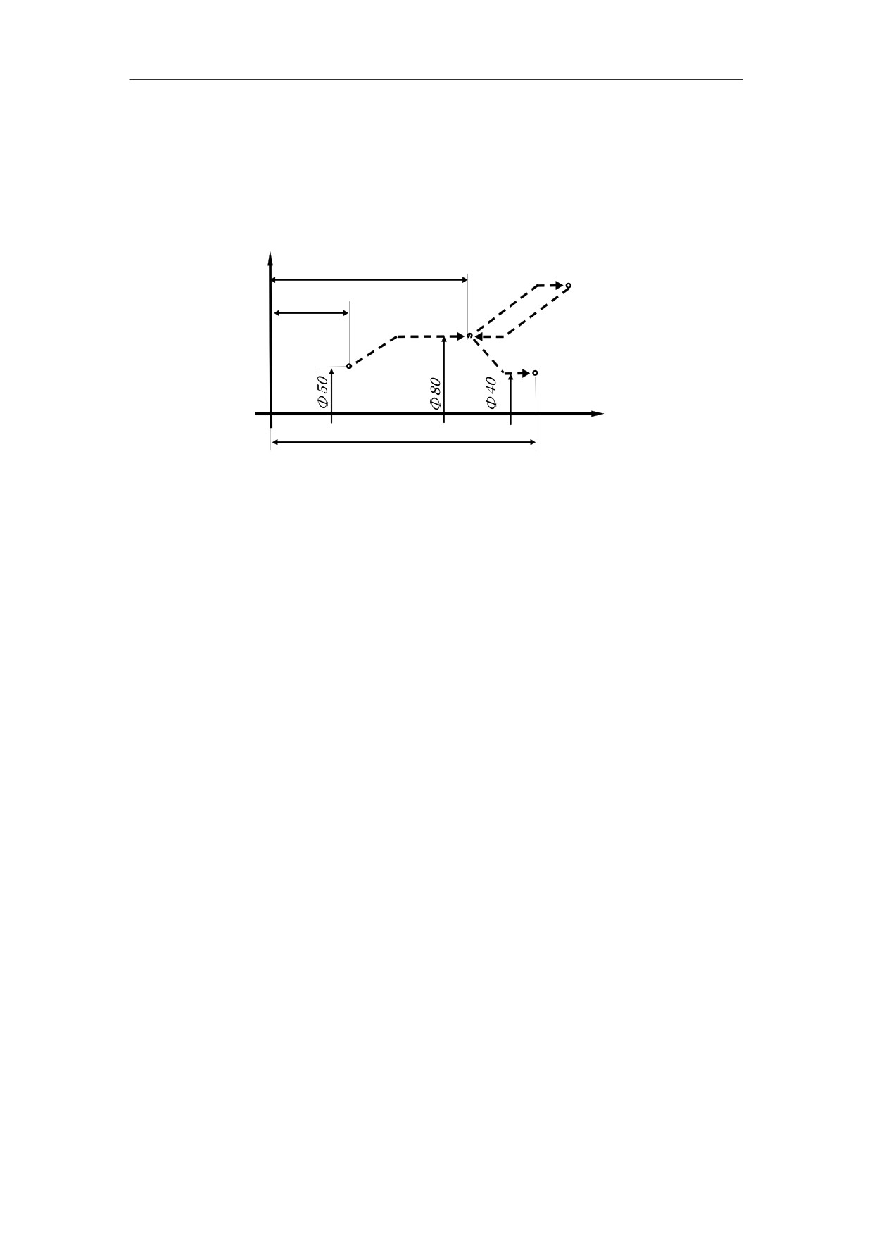
Example
Use G28, G29 command to program the track shown in. It moves from the starting
point A to the intermediate point B, and then returns to the reference point R. At last, it
moves from the reference point R to the end point C through the intermediate point B.
+X
200
R
100
B
A
C
+Z
250
Figure 5.2 Reference Position - Example
%3317
N1 T0101
N2 G00 X50 Z100
N3 G28 X80 Z200
N4 G29 X40 Z250
N5 G00 X50Z100
N6 M30
66
5. Coordinate System
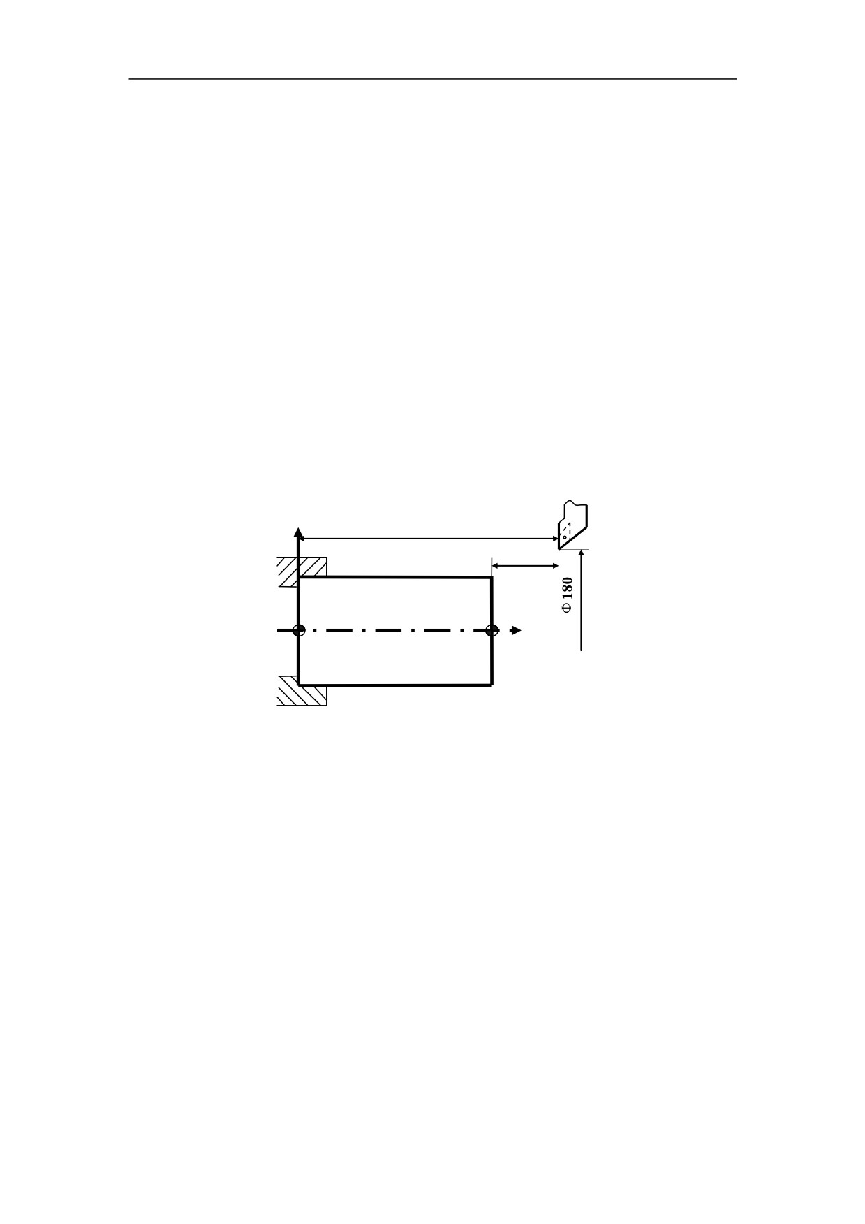
5.3 Setting a Workpiece Coordinate System (G92)
Programming
G92 X_ Z_
Explanation of the parameters
X, Z
Coordinate values of the tool position in the workpiece coordinate system.
Functions
G92 can set a workpiece coordinate system based on the current tool position (X_
Z_).
Example
Use G92 to set a workpiece coordinate system.
+X
254
44
+Z
Origin on
Origin on
left end face
right end face
Figure 5.3 Setting a Coordinate System - Example
If the origin is set on the left end face,
G92 X180 Z254
If the origin is set on the right end face
G92 X180 Z44
67
5. Coordinate System
5.4 Selecting a Machine Cooridinate System (G53)
Programming
G53 X_Z_
Explanation of the parameters
X, Z
Absoulte coordinate values of a point in the machine coordinate system.
Function
A machine coordinate system is selected, and the tool moves to the position at the
rapid traverse speed.
Note:
1) Absolute values must be specified in G53. The incremental values would be
ignored by G53.
2) G53 is one-shot G code.
68
5. Coordinate System
5.5 Selecting a Workpiece Coordinate System
(G54~G59)
Programming
G54
G55
G56
X_ Z_
G57
G58
G59
Explanation of the parameters
X, Z
Coordinate values of the point in absolute command
Function
There are six workpiece coordinate system to be selected. If one coordinate system is
selected, the tool is moved to a specified point.
Note:
1) The workpiece coordinate system must be set before these commands
(G54~G59) are used. The workpiece coordinate system can be set by using
the MDI panel. For detailed information, please refer to the turning operation
manual.
2) Reference position must be returned before these commands (G54~G59)
are executed.
3) G54 is the default setting.
69
5. Coordinate System
Example
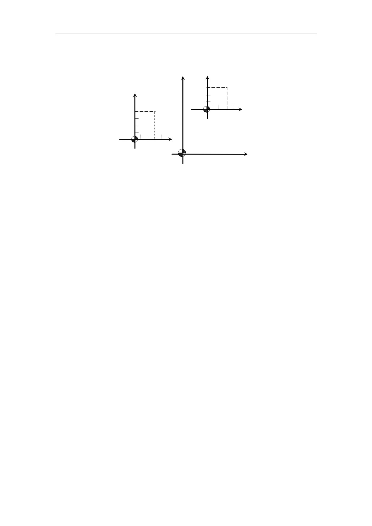
Select one of workpiece coordinate system, and the tool path is Current point→A→B.
X
30
B
X
A
40
G59
O
30
Z
G54
O
30
Z
Machine Zero Point
Figure 5.4 Workpiece Coordinate System - Example
%3303
N01 G54 G00 G90 X40 Z30
N02 G59
N03 G00 X30 Z30
N04 M30
70
5. Coordinate System
5.6 Origin of a Workpiece Coordinate System (G51,
G50)
Programming
G51 U_ W_
G50
Explanation of the parameters
G51 can move the origin of workpiece coordinate system.
U, W Coordinate values of the position in incremental command
G50 can cancel the movement.
Function
The origin of workpiece coordinate system can be moved.
Note:
1) G51 is only effective when T command or G54~G59
is
defined
in
the
program.
2) G50 is only effective when T command or G54~G59
is
defined
in
the
program.
Example
%1234
G51 U30 W10
%1111
M98 P1111 L4
T0101
G50
G01 X32 Z25
T0101
G01 X34.444 Z99.123
G01 X30 Z14
M99
M30
71
5. Coordinate System
5.7 Absolute and Incremental Programming (G90, G91)
Programming
G90 X_ Z_
G91 U_W_
Explanation of the parameters
G90 Absolute programming
X, Z
Coordinate values on X axis and Z axis in the coordinate system
G91 Incremental programming
U, W Coordinate values with reference to the previous position in the coordinate
system
Function
The tool is moved to the specified position.
72
5. Coordinate System
Example
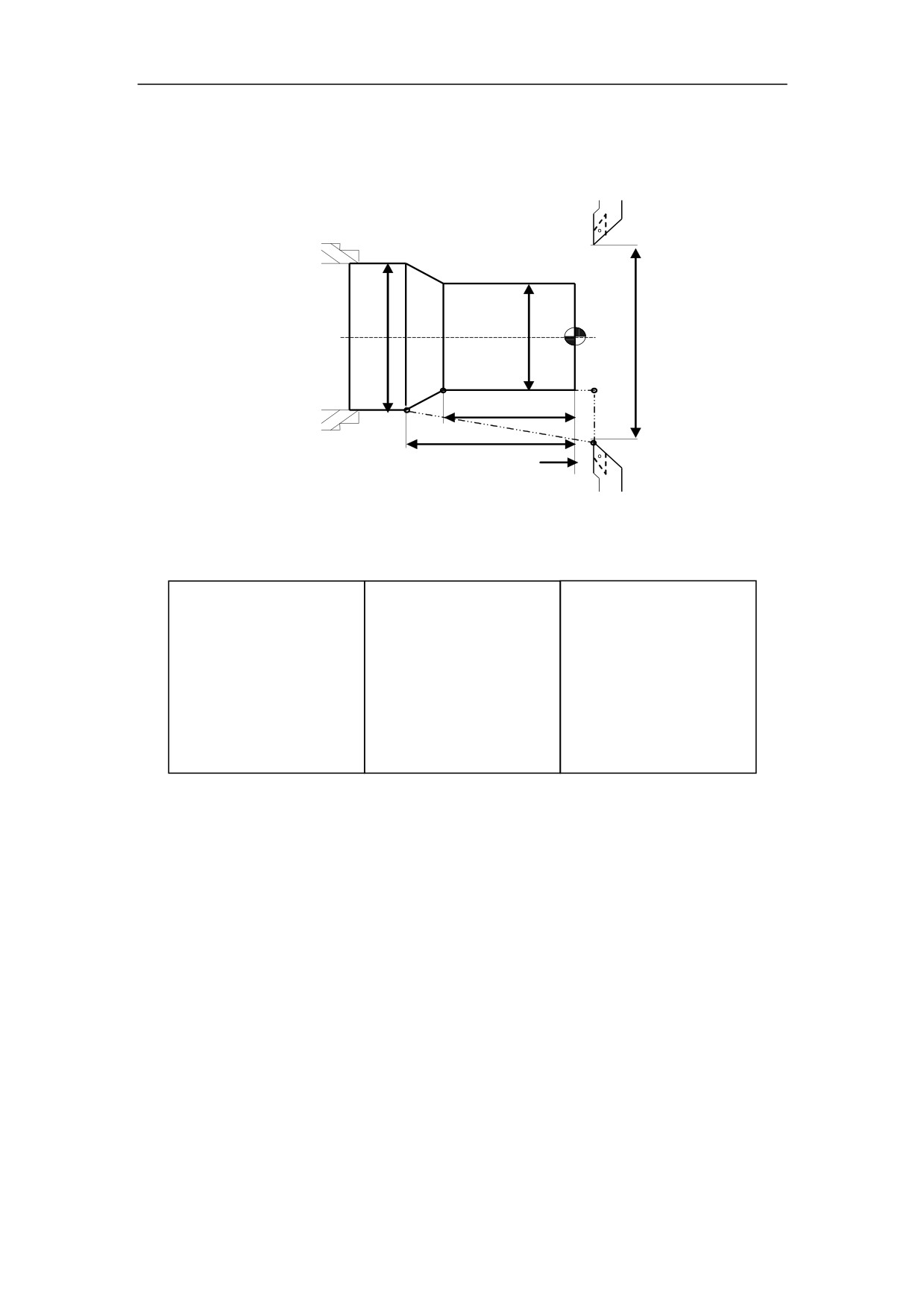
Move the tool from point 1 to point 2 through point 3, and then return to the current
point.
Φ25
Φ15
Φ50
3
2
1
30
4
40
1
2
Figure 5.5 Absolute and Incremental Programming - Example
Absolute Programming
Incremental Programming Absolute and Incremental
%0001
%0001
%0001
N 1 T0101
N 1 M03 S460
N 1 T0101
N 2 M03 S460
N 2 G91 G01 X-35
N 2 M03 S460
N3 G90 G00 X50 Z2
N 3 Z-32
N 3 G00 X50 Z2
N4 G01 X15
N 4 X10 Z-10
N 4 G01 X15
N 5 Z-30
N 5 X25 Z42
N 5 Z-30
N 6 X25 Z-40
N 6 M30
N 6 U10 Z-40
N 7 X50 Z2
N 7 X50 W42
N 8 M30
N 8 M30
73
5. Coordinate System
5.8 Diameter and Radius Programming (G36, G37)
Programming
G36
G37
Explanation of the parameters
G36 Diameter programming
G37 Radius programming
Function
The coordinate value on X axis is specified in two ways: diameter or radius. It allows
to program the dimension straight from the drawing without conversion.
Note:
1) In all the examples of this book, we always use diameter programming if the
radius programming is not specified.
2) If the machine parameter is set to diameter programming, then diameter
programming is the default setting. However, G36 and G37 can be used to
exchange. The system shows the diameter value.
3) If the system parameter is set to radius programming, then radius
programming is the default setting. However, G36 and G37 can be used to
exchange. The system shows the radius value.
74
5. Coordinate System
Example
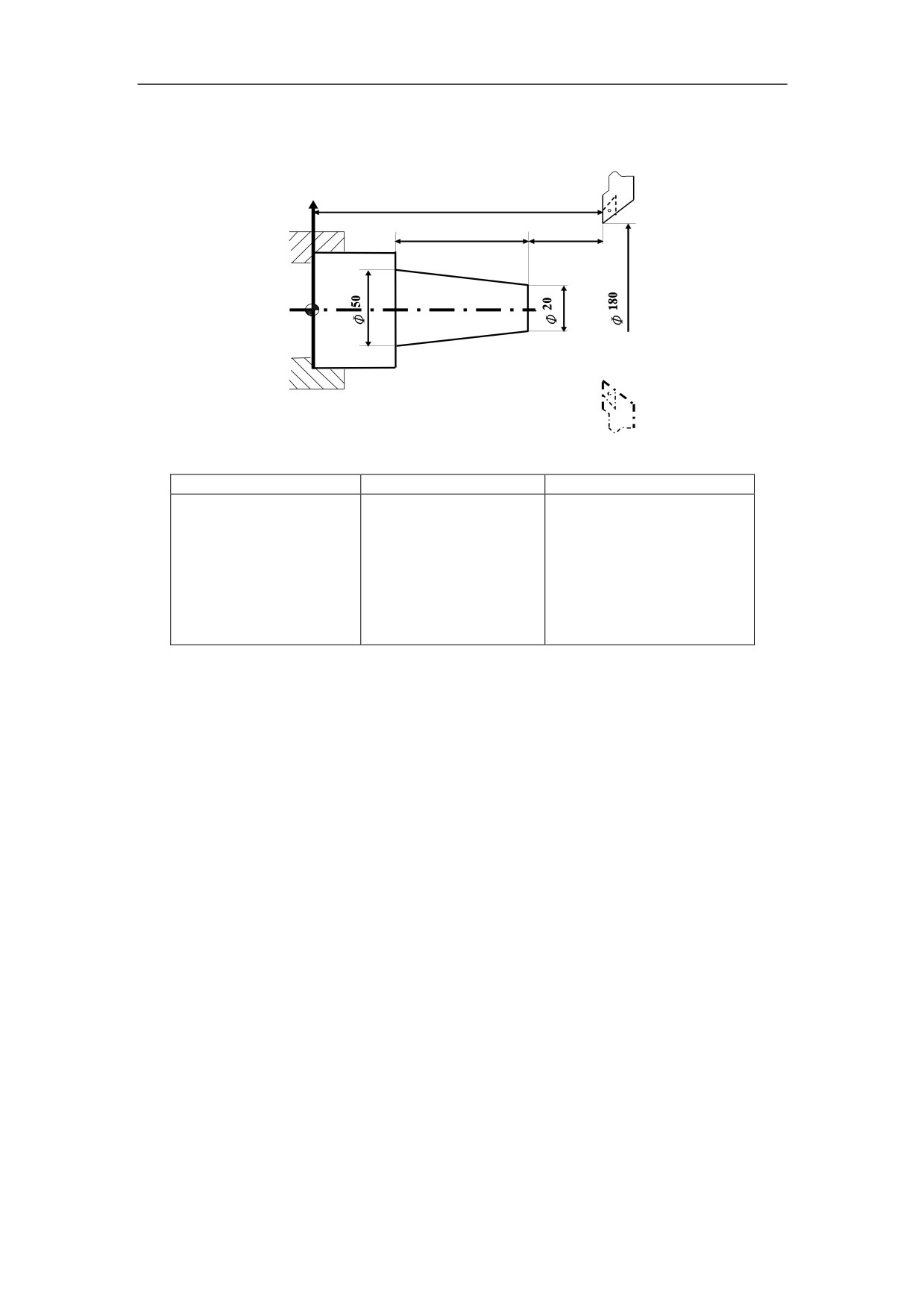
Use Diameter programming and Radius programming for the same path
+X
254
160
44
Figure 5.6 Diameter and Radius Programming - Example
Diameter Programming Radius Programming
Compound Programming
%3304
%3314
%3314
N1 G92 X180 Z254
N1 G37 M03 S460
N1 T0101
N2 M03 S460
N2 G54 G00 X90 Z254
N2 M03 S460
N3 G01 X20 W-44
N3 G01 X10 W-44
N3 G37G00 X90 Z254
N4 U30 Z50
N4 U15 Z50
N4 G01 X10 W-44
N5 G00 X180 Z254
N5 G00 X90 Z254
N5 G36 U30 Z50
N6 M30
N6 M30
N6 G00 X180 Z254
N7 M30
75
5. Coordinate System
5.9 Inch/Metric Conversion (G20, G21)
Programming
G20
G21
Explanation of the parameters
G20: Inch input
G21: Metric input
The units of linear axis and circular axis are shown in the following table
Table 5-1. Unit of Linear axis and Circular axis
Linear axis
Circular axis
Inch system (G20)
Inch
Degree
Metric system (G21)
Mm
Degree
Function
Depending on the part drawing, the workpiece geometries can be programmed in
metric measures or inches.
76
5. Coordinate System
5.10 Changing Coordinate and Tool Offset
(Programmable Data Input) (G10)
Programming
G10P__X__Z__I__K__R__Q__
G10P__X__Y__Z__
Explanation of the parameters
1.
Command type is set by P.
P53: modify the machine coordinate system
P54~P59: modify G54~G59, for example, P54 is to modify G54
P92: modify the current workpiece coordinate system
P101~P132: the modified tool number, for example, P101 corresponds to T01.
2.
Modifying coordinates (P53, P54~P59, P92)
X, Y, Z: the value and origin of coordinates. P53 is used to modify the current
position of machine coordinate system. P54~P59 and P92 are used to modify the
origin of the coordinates.
When G90 is used, the value and origin of coordinates are directly assigned
to the specified coordinates.
When G91 is used, the coordinate value and origin are assigned to the
specified coordinates in an incremental way.
3.
Modifying tool offset
X: the tool offset in the X-direction
Z: the tool offset in the Z-direction
U: the tool offset in the X-direction (incremental way)
W: the tool offset in the X-direction (incremental way)
I:
the tool wear-out in the X-direction
K: the tool wear-out in the Z-direction
R: the tool radius. It is used to set the current tool radius
Q: the direction of tool tip. The range is 0~8. The other values are invalid.
According to G90/G91, the data of parameters X, Z, I, K, R could be absolute or
incremental.
When G90 is used, the data of parameters X, Z, I, K, R is directly set to the tool
77
5. Coordinate System
parameters.
When G91 is used, the data of parameters X, Z, I, K, R is set to the tool
parameters in an incremental way.
For example:
G91 G10 P101 X40 Z10
G90 G10 P101 X40 G91 Z10
Function
It is used to modify the coordinate system, the tool offset and compensation.
78
6. Spindle Speed Function
6 Spindle Speed Function
Spindle function controls the spindle speed (S), the unit of spindle speed is r/min.
Spindle speed is the cutting speed when it is at the constant speed, the unit of speed
is m/min.
S is modal G code command; it is only available when the spindle is adjustable.
Spindle speed programmed by S code can be adjusted by overrides on the machine
control panel.
This chapter would introduce
1) Limit of spindle speed (G46)
2) Constant surface cutting control (G96, G97).
79
6. Spindle Speed Function
6.1 Limit of Spindle Speed (G46)
Programming
G46 X_ P_
Explanation of the parameters
X The minimum speed of the spindle when using constant surface speed(r/min)
P The maximum speed of the spindle when using constant surface speed(r/min)
Function
G46 command can set the minimum of spindle speed, and the maximum of spindle
speed.
Note:
It can only used with G96 (constant surface speed control command).
80
6. Spindle Speed Function
6.2 Constant Surface Speed Control (G96, G97)
Programming
G96 S
G97 S
Explanation of the parameters
G96 activate the constant surface speed
S
surface speed (m/min)
G97 deactivate the constant surface speed
S
spindle speed (r/min)
Function
G96 and G97 commands are to control the constant surface speed.
Note:
1) The spindle speed must be controlled automatically when the constant
surface cutting command is executed.
2) The maximum of spindle speed can be set by the axis parameter.
81
6. Spindle Speed Function
Example
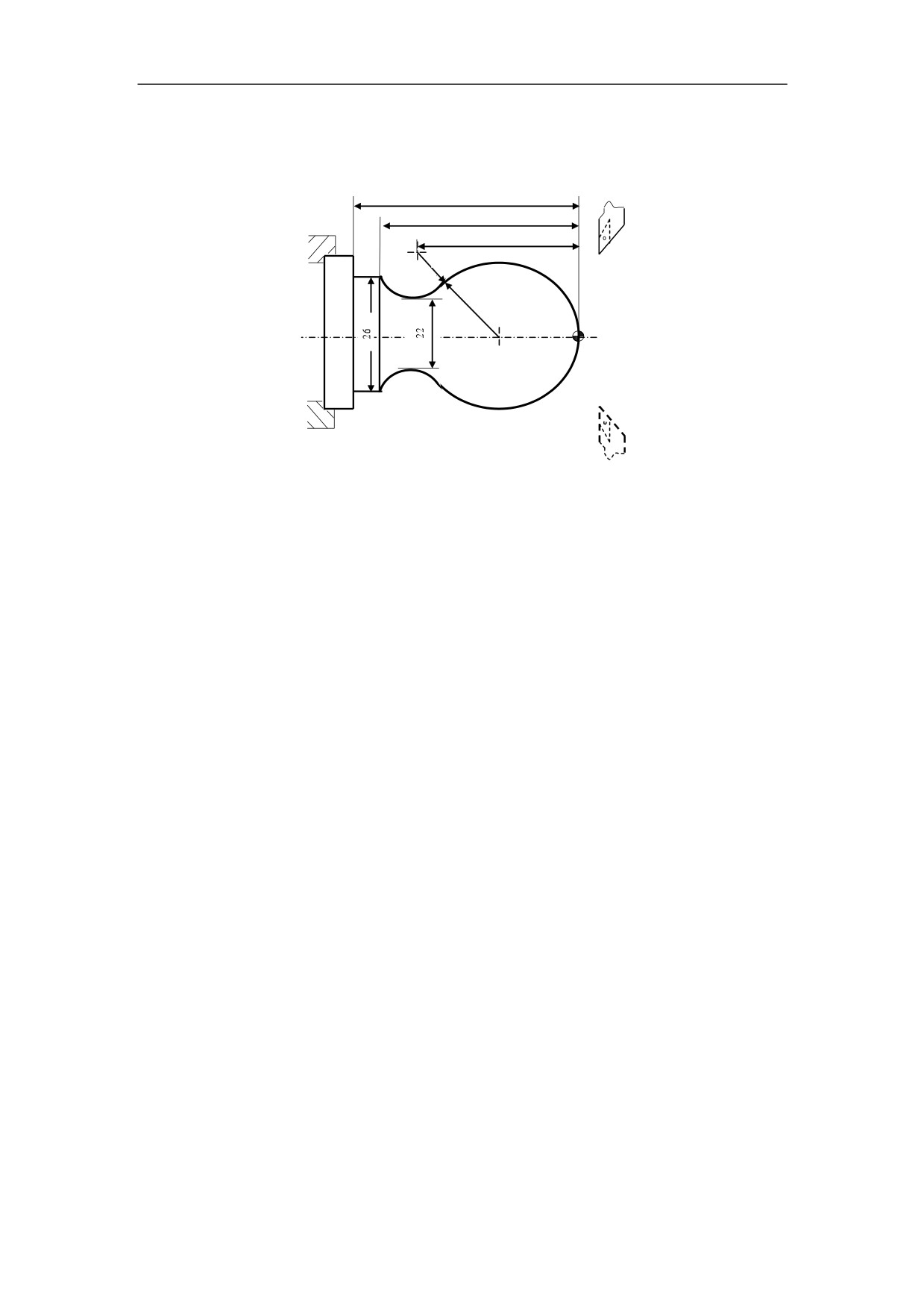
Use the constant surface control command
40
31
27
R15
Figure 6.1 Constant Surface Control - Example
%3318
N1 T0101
N2 G00 X40 Z5
N3 M03 S460
N4 G96 S80
N5 G46 X400 P900
N5 G00 X0
N6 G01 Z0 F60
N7 G03 U24 W-24 R15
N8 G02 X26 Z-31 R5
N9 G01 Z-40
N10 X40 Z5
N11 G97 S300
N12 M30
82
7. Tool Function
7 Tool Compensation Function
There are two types of tool compensation. One is geometry compensation and the
other is radius compensation. The tool geometry compensation is categorized as tool
offset compensation and tool wear compensation. The tool offset compensation is
categorized as absolute tool offset compensation and relative tool offset
compensation.
Statement: T code is used in the tool geometry compensation (the sum of offset and
wear compensation). G40, G41, and G42 are set for tool radius compensation.
This chapter would introduce:
1) Tool offset and Tool wear-out compensation (T code)
2) Tool radius compensation (G40, G41, G42)
83
7. Tool Function
7.1 Tool Offset and Tool Wear Compensation
The trajectory of the turning machine programming is the tool nose movement
trajectory. But actually, the geometry size and installation position of different cutting
tool is varied, the cutter point relative to the tool center position is also different.
Therefore, it needs to measure the tool nose position in order to compensate for the
tool offset during the machining process. So there is no need to consider tool shape
and install position causing the position consistency of tool tip to simplify programming.
There are two types of tool offset compensation.
7.1.1 Tool Offset
1. Absolute compensation mode
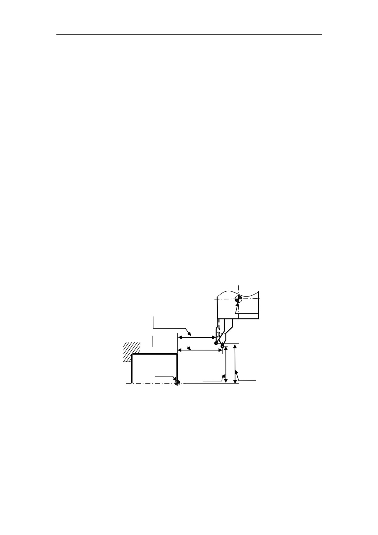
As it is shown in Figure7.1, the absolute offset means the workpiece origin relative to
the directed distance of the tool nose position on the cutter frame, when the machine
returns to workpiece origin. When executing tool offset compensation, tools use this
value to set the coordinates. Therefore, although the cutter frame is on the machine
origin, the distance of tool position relative to workpiece origin is different caused by
the different sizes of the cutters. These set coordinates coincide with the workpiece
coordinates (programming).
Workpiece origin
No.1 tool offset
on axis Z
Z1
No.2 tool offset
Z2
on axis Z
X
2/2
X1/2
Workpiece origin
No.2 tool offset
on axis X
Figure 7.1 Absolute tool offset compensation
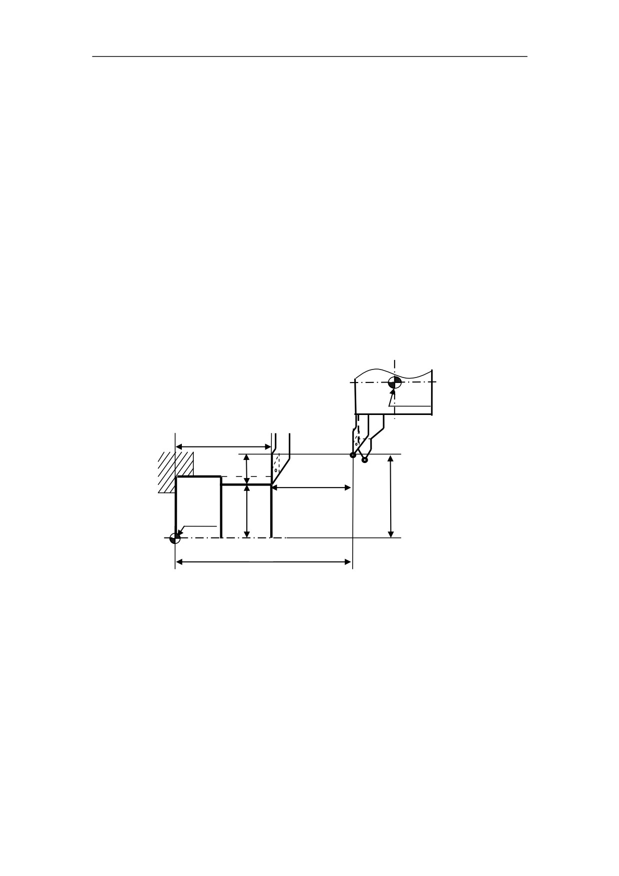
As it is shown in Figure7.2, when the machine is reached the machine origin, the
value of machine coordinate system is zero, and the point on the cutter frame is
regarded as the ideal point. Thus, when the tool is aligned, it is considered that the
machine origin is on the cutter position. The system can automatically calculate the
distance of workpiece origin relative to the tool position by the input trial diameter and
length. The procedure is as followed:
84
7. Tool Function
1) Press “Tool Offset” function key;
2) Input the workpiece coordinates value of the tool on axis Z in the trial face
cutting of the workpiece. Input 0 if the workpiece origin is set at the front face
of workpiece (no movement on axis Z before setting zero). The system would
automatically calculate the distance of the workpiece origin relative to the tool
position on axis Z.
3) Input the workpiece coordinates value of the tool on axis X in the trial
cylindrical surface cutting of the workpiece. It is the diameter of workpiece
after trial cutting (no movement on axis X before setting zero). The system
would automatically calculate the distance of the workpiece origin relative to
the tool position on axis X.
4) Change a tool and use another tool to repeat the above steps 2~3. The
absolute tool offset of this tool can be get, and automatically input to the table
of tool offset.
Machine origin
Zw
DM/2
ZM
Dw/2
workpiece
DM′/2
origin
ZM′
Figure 7.2 Setting the absolute tool offset compensation
2. Relative compensation mode
As it is shown in Figure7.3, one tool is set as a standard tool when aligning tool, and
the coordinates is set based on the position A of this tool tip. When the other tools are
at the machining position, the position B of tool tip relative to position A would arise
the offset, and the original coordinates would not be applicable. Thus, the offset △x
and △z are used, and the tool tip is moved from position B to A. The compensation is
implemented by controlling the movement of machine carriage in this system.
85