Century Star Turning CNC System. Programming Guide (V3.5 April, 2015) - page 1
Preface
Preface
Organization of documentation
1. General
2. Preparatory Function
3. Interpolation Function
4. Feed Function
5. Coordinate System
6. Spindle Speed Function
7. Tool Function
8. Miscellaneous Function
9. Functions to Simplify Programming
10. Comprehensive Programming Example
11. Custom Macro
Applicability
This Programming Guide is applicable to the following CNC system:
HNC-18iT/19iT v4.0
HNC-18xp/T
HNC-180xp/T
HNC-19xp/T
HNC-21TD/22TD v05.62.07.10
Internet Address
Table of Contents
Table of Contents
PREFACE
I
TABLE OF CONTENTS
II
1 GENERAL
1
1.1
CNC PROGRAMMING
2
1.2
INTERPOLATION
4
1.2.1
Linear Interpolation
4
1.2.2
Circular Interpolation
5
1.2.3
Thread Cutting
5
1.3
FEED FUNCTION
6
1.4
COORDINATE SYSTEM
7
1.4.1
Reference Point
7
1.4.2
Machine Coordinate System
8
1.4.3
Workpiece Coordinate System
9
1.4.4
Setting Two Coordinate Systems at the Same Position
10
1.4.5
Absolute Commands
11
1.4.6
Incremental Commands
12
1.4.7
Diameter/Radius Programming
13
1.5
SPINDLE SPEED FUNCTION
14
1.6
TOOL FUNCTION
15
1.6.1
Tool Selection
15
1.6.2
Tool Offset
15
1.7
MISCELLANEOUS FUNCTION
18
1.8
PROGRAM CONFIGURATION
19
1.8.1
Structure of an NC Program
19
1.8.2
Main Program and Subprogram
20
2 PREPARATORY FUNCTION (G CODE)
21
2.1
G CODE LIST
22
3 INTERPOLATION FUNCTIONS
24
3.1
POSITIONING (G00)
25
3.2
LINEAR INTERPOLATION (G01)
26
3.3
CIRCULATION INTERPOLATION (G02, G03)
30
3.4
CHAMFERING AND ROUNDING (G01, G02, G03)
36
3.4.1
Chamfering (G01)
36
3.4.2
Rounding (G01)
37
3.4.3
Chamfering (G02, G03)
39
3.4.4
Rounding (G02, G03)
40
3.5
THREAD CUTTING WITH CONSTANT LEAD (G32)
42
3.6
TAPPING (G34)
46
3.7
DIRECT DRAWING DIMENSION PROGRAMMING (G01)
49
3.7.1
Instruct a line
49
3.7.2
Rounding
50
3.7.3
Chamfering
51
3.7.4
Continuous Rounding
53
3.7.5
Continuous Chamfering
54
3.7.6
Rounding then Chamfering
55
3.7.7
Chamfering then Rounding
57
4 FEED FUNCTION
59
ii
Table of Contents
4.1
RAPID TRAVERSE (G00)
60
4.2
CUTTING FEED (G94, G95)
61
4.3
DWELL (G04)
62
5 COORDINATE SYSTEM
63
5.1
REFERENCE POSITION RETURN (G28)
64
5.2
AUTO RETURN FROM REFERENCE POSITION (G29)
65
5.3
SETTING A WORKPIECE COORDINATE SYSTEM (G92)
67
5.4
SELECTING A MACHINE COORIDINATE SYSTEM (G53)
68
5.5
SELECTING A WORKPIECE COORDINATE SYSTEM (G54~G59)
69
5.6
ORIGIN OF A WORKPIECE COORDINATE SYSTEM (G51, G50)
71
5.7
ABSOLUTE AND INCREMENTAL PROGRAMMING (G90, G91)
72
5.8
DIAMETER AND RADIUS PROGRAMMING (G36, G37)
74
5.9
INCH/METRIC CONVERSION (G20, G21)
76
5.10
CHANGING COORDINATE AND TOOL OFFSET (PROGRAMMABLE DATA INPUT) (G10)
77
6 SPINDLE SPEED FUNCTION
79
6.1
LIMIT OF SPINDLE SPEED (G46)
80
6.2
CONSTANT SURFACE SPEED CONTROL (G96, G97)
81
7 TOOL COMPENSATION FUNCTION
83
7.1
TOOL OFFSET AND TOOL WEAR COMPENSATION
84
7.1.1
Tool Offset
84
7.1.2
Tool Wear-out
87
7.2
TOOL RADIUS COMPENSATION (G40, G41, G42)
90
8 MISCELLANEOUS FUNCTION
93
8.1
M CODE LIST
94
8.2
CNC M-FUNCTION
95
8.2.1
Program Stop (M00)
95
8.2.2
Optional Stop (M01)
95
8.2.3
End of Program (M02)
95
8.2.4
End of Program with return to the beginning of program (M30)
95
8.2.5
Counting (M64)
95
8.2.6
User-defined Input and Output (M90, M91)
96
8.2.7
Saving Macro (M94)
97
8.2.8
Subprogram Control (M98, M99)
97
8.3
PLC M FUNCTION
99
8.3.1
Spindle Control (M03, M04, M05)
99
8.3.2
Coolant Control (M07, M08, M09)
99
9 FUNCTIONS TO SIMPLIFY PROGRAMMING
100
9.1
CANNED CYCLES
101
9.1.1
Internal Diameter/Outer Diameter Cutting Cycle (G80)
101
9.1.2
End Face Turning Cycle (G81)
106
9.1.3
Thread Cutting Cycle (G82)
109
9.1.4
End Face Peck Drilling Cycle (G74)
112
9.1.5
Outer Diameter Grooving Cycle (G75)
113
9.2
MULTIPLE REPETITIVE CYCLE
115
9.2.1
Stock Removal in Turning (G71)
115
9.2.2
Stock Removal in Facing (G72)
121
9.2.3
Pattern Repeating (G73)
125
9.2.4
Multiple Thread Cutting Cycle (G76)
128
10
COMPREHENSIVE PROGRAMMING
131
10.1
EXAMPLE 1
131
10.2
EXAMPLE 2
133
iii
Table of Contents
10.3
EXAMPLE 3
135
10.4
EXAMPLE 4
136
11
CUSTOM MACRO
137
11.1
VARIABLES
138
11.1.1 Type of Variables
138
11.1.2 System Variables
139
11.1.3 Memorable User-defined Variables
144
11.2
CONSTANT
145
11.3
OPERATORS AND EXPRESSION
146
11.4
ASSIGNMENT
147
11.5
SELECTION STATEMENT IF, ELSE,ENDIF
148
11.6
REPETITION STATEMENT WHILE, ENDW
149
11.7
MACRO CALL
150
11.8
EXAMPLE
152
iv
1. General
1 General
This chapter is to introduce the basic concepts in Computerized Numerical Control
(CNC) system: HNC-21T/22T, HNC-18iT/19iT, HNC-18xp/T, HNC-180xp/T,
HNC-19xp/T.
1
1. General
1.1 CNC Programming
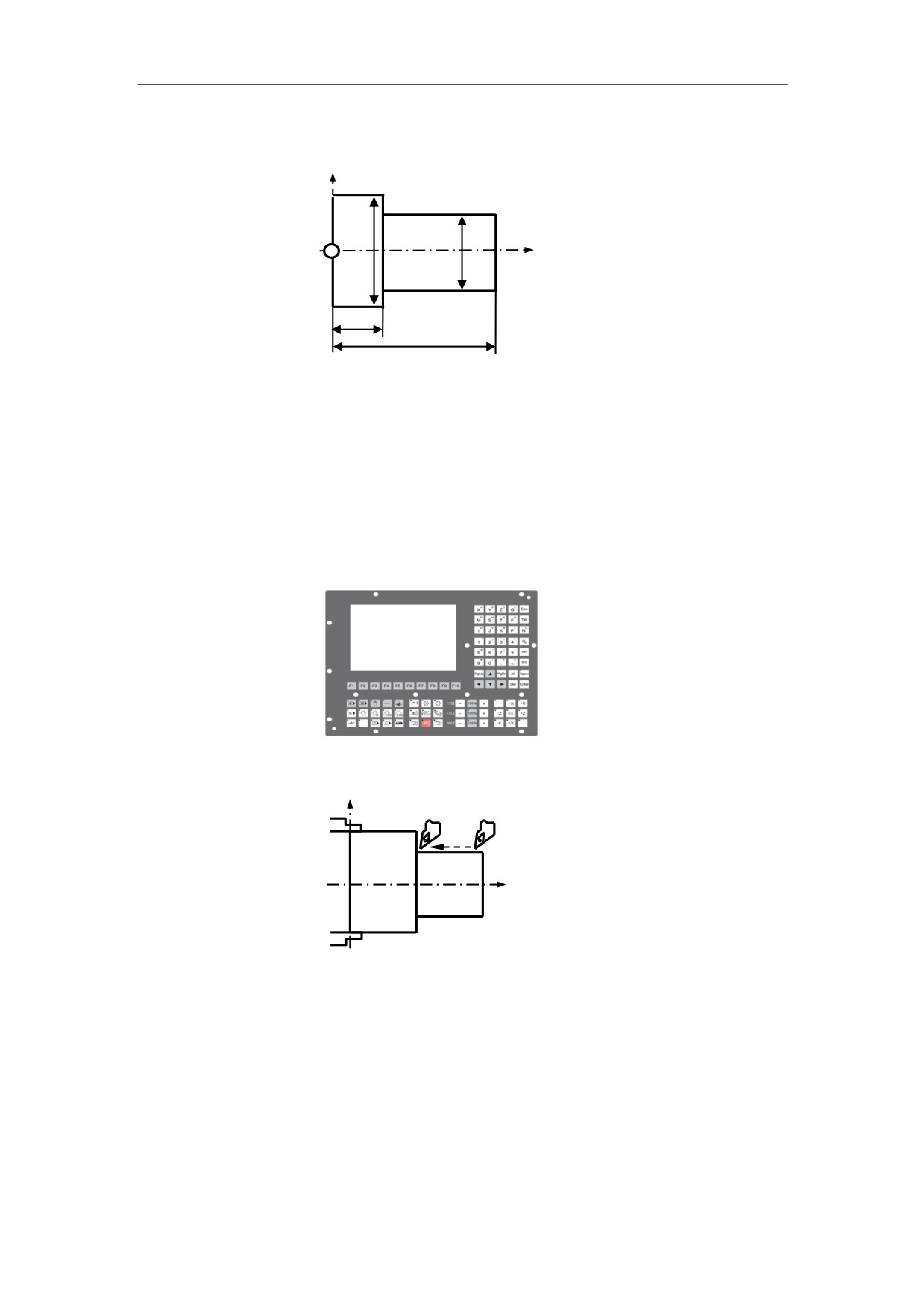
To operate CNC machine tool, the first step is to understand the part drawing and
produce a program manual script. The procedure for machining a part is as follows
(Figure 1.1):
1) Read drawing
2) Produce the program manual script
3) Input the program manual script by using the machine control panel
4) Manufacture a part
2
1. General
1. Read drawing
X
40
150
2. Produce the program manual script
N1 T0106
N2 M03 S460
N3 G00 X90Z20
N4 G00 X31Z3
N5 G01 Z-50 F100
N6 G00 X36
N7 Z3
…
3. Input the program manual script
4. Manufacture a part
X
Z
Figure 1.1 The workflow of operation of CNC machine tool
3
1. General
1.2 Interpolation
Interpolation refers to an operation in which the machine tool moves along the
workpiece parts. There are five methods of interpolation: linear, circular, helical,
parabolic, and cubic. Most CNC machine can provide linear interpolation and circular
interpolation. The other three methods of interpolation (helical, parabolic, and cubic
interpolation) are usually used to manufacture the complex shapes, such as
aerospace parts. In this manual, linear and circular interpolation are introduced.
1.2.1 Linear Interpolation
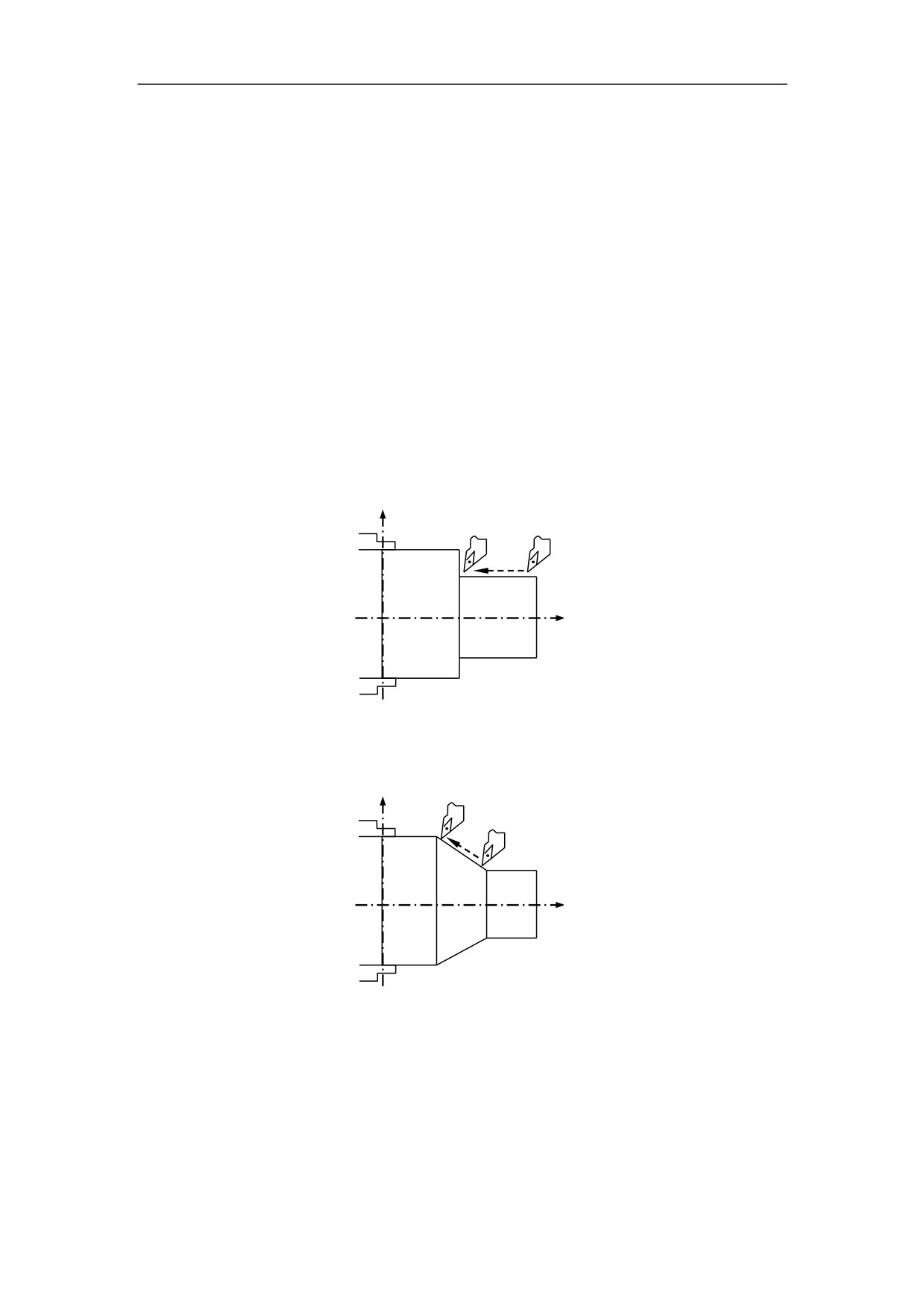
There are two kinds of linear interpolation:
1) Tool movement along a straight line (Figure 1.2).
X
Z
Figure 1.2 Linear Interpolation (1)
2) Tool movement along the taper line
X
Z
Figure 1.3 Linear Interpolation (2)
4
1. General
1.2.2 Circular Interpolation
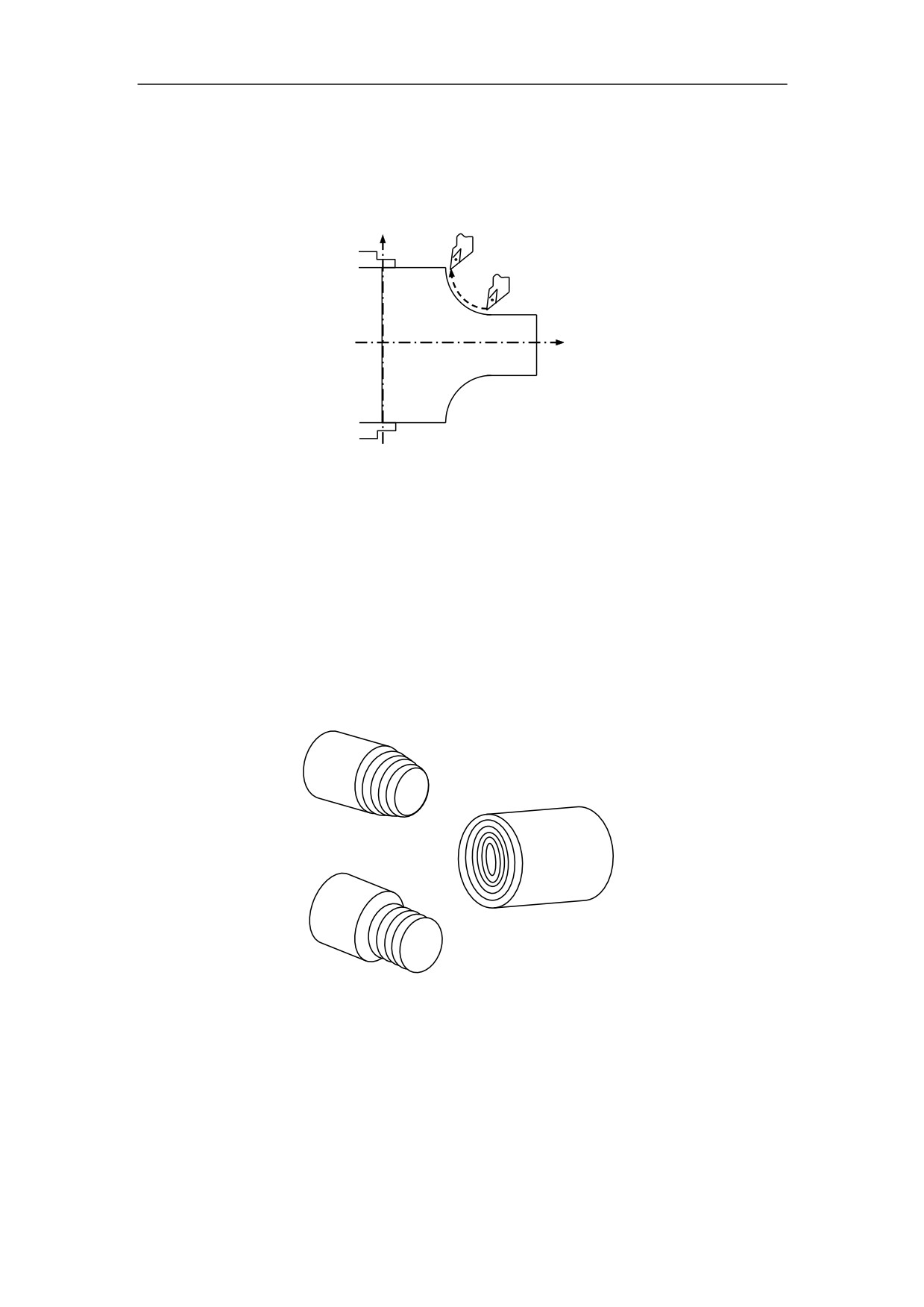
Figure 1.4 shows a tool movement along an arc.
X
Z
Figure 1.4 Circular Interpolation
Note:
In this manual, it is assumed that tools are moved against workpieces.
1.2.3 Thread Cutting
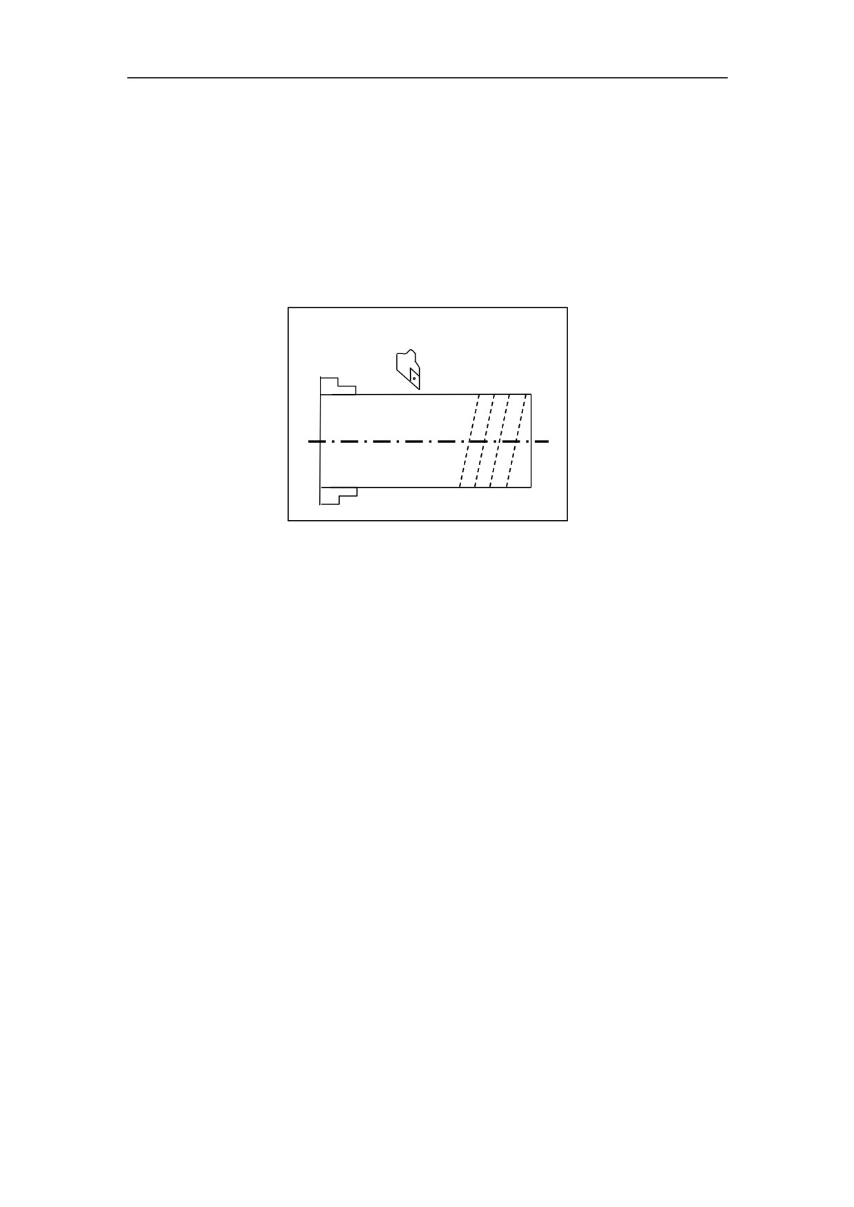
There are several kinds of threads: cylindrical, taper or face threads. To cut threads on
a workpiece, the tool is moved with spindle rotation synchronously.
Figure 1.5 Thread Cutting
5
1. General
1.3 Feed Function
-
Feed refers to an operation in which the tool moves at a specified speed to cut a
workpiece.
-
Feedrate refers to a specified speed, and numeric is used to specified the
feedrate.
-
Feed function refers to an operation to control the feedrate.
Tool
Chuck
Figure 1.6 Feed Function
For example:
F2.0
//feed the tool 2mm, while the workpiece makes one turn
6
1. General
1.4 Coordinate System
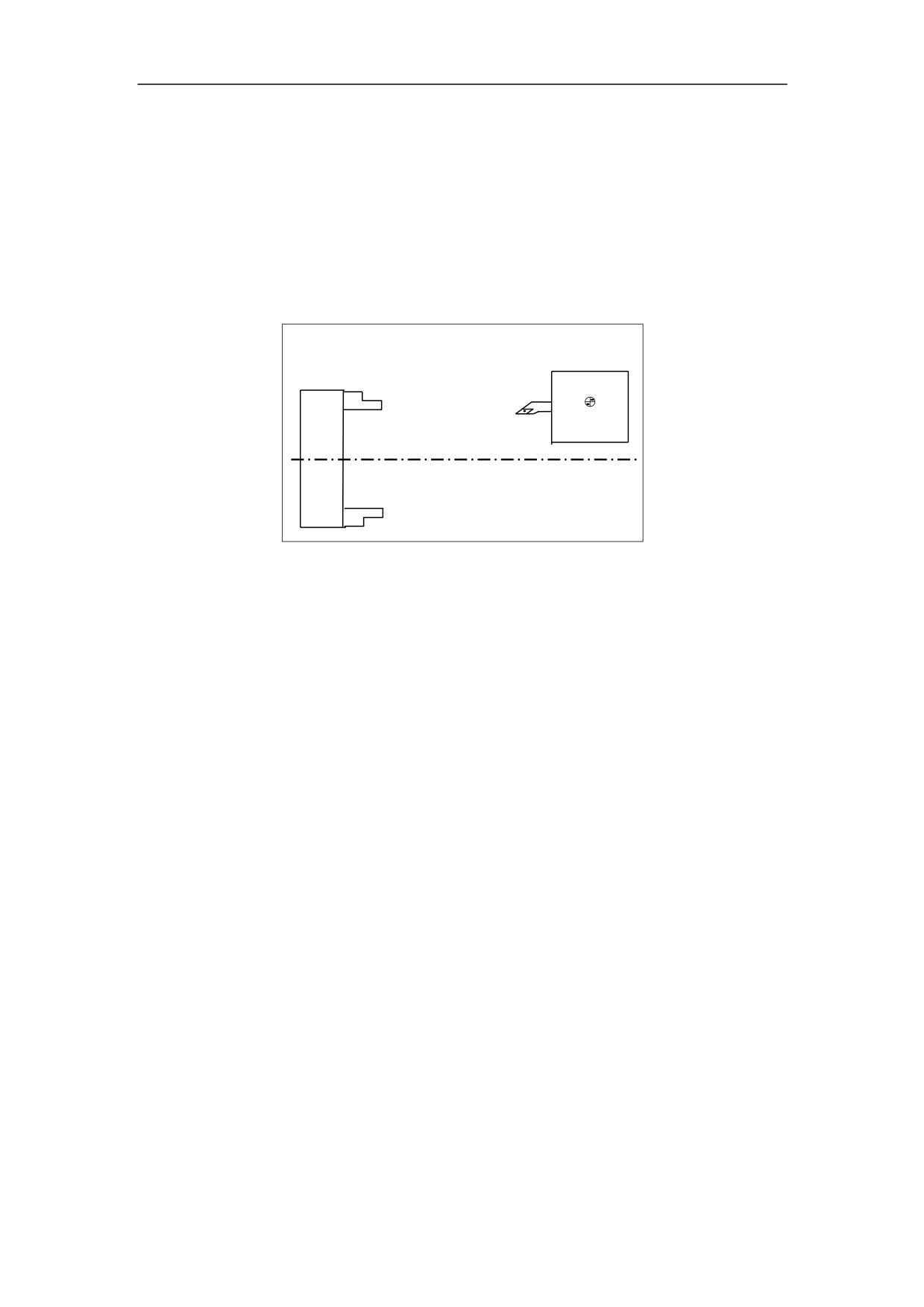
1.4.1 Reference Point
Reference point is a fixed position on CNC machine tool, which is determined by
cams and measuring system. Generally, it is used when the tool is required to
exchange or the coordinate system is required to set.
Tool post
Chuck
Reference
position
Figure 1.7 Reference Point
There are two ways to move to the reference point:
-
Manual reference position return: The tool is moved to the reference point by
operating the button on the machine control panel. It is only used when the
machine is turned on.
-
Automatic reference position return: It is used after the manual reference position
return has been used. In this manual, this would be introduced.
7
1. General
1.4.2 Machine Coordinate System
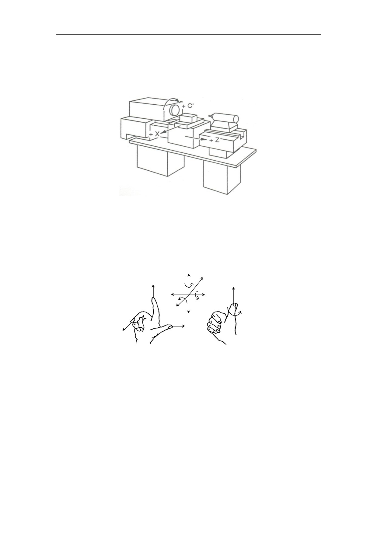
The coordinate system is set on a CNC machine tool. Figure 1.8 is a machine
coordinate system of turning machine, and shows the direction of axes:
Figure 1.8 Machine Coordinate System
In general, three basic linear coordinate axes of motion are X, Y, Z. Moreover, X, Y, Z
axis of rotation is named as A, B, C correspondently. Due to different types of turning
machine, the axis direction can be decided by following the rule - “three finger rule” of
the right hand.
+Y
+B
+Z'
+X +Y +Z
+Y
+X'
+X
+C
+A
+Z
+A +B
+Y'
+C
+X
+Z
Figure 1.9 “three finger rule”
-
The thumb points the X axis. X axis controls the cross motion of the cutting
tool. “+X” means that the tool is away from the spindle centerline
-
The index points the Y axis. Y axis is usually a virtual axis.
-
The middle finger points the Z axis. Z axis controls the motion of the cutting
tool. “+Z” means that the tool is away from the spindle.
8
1. General
1.4.3 Workpiece Coordinate System
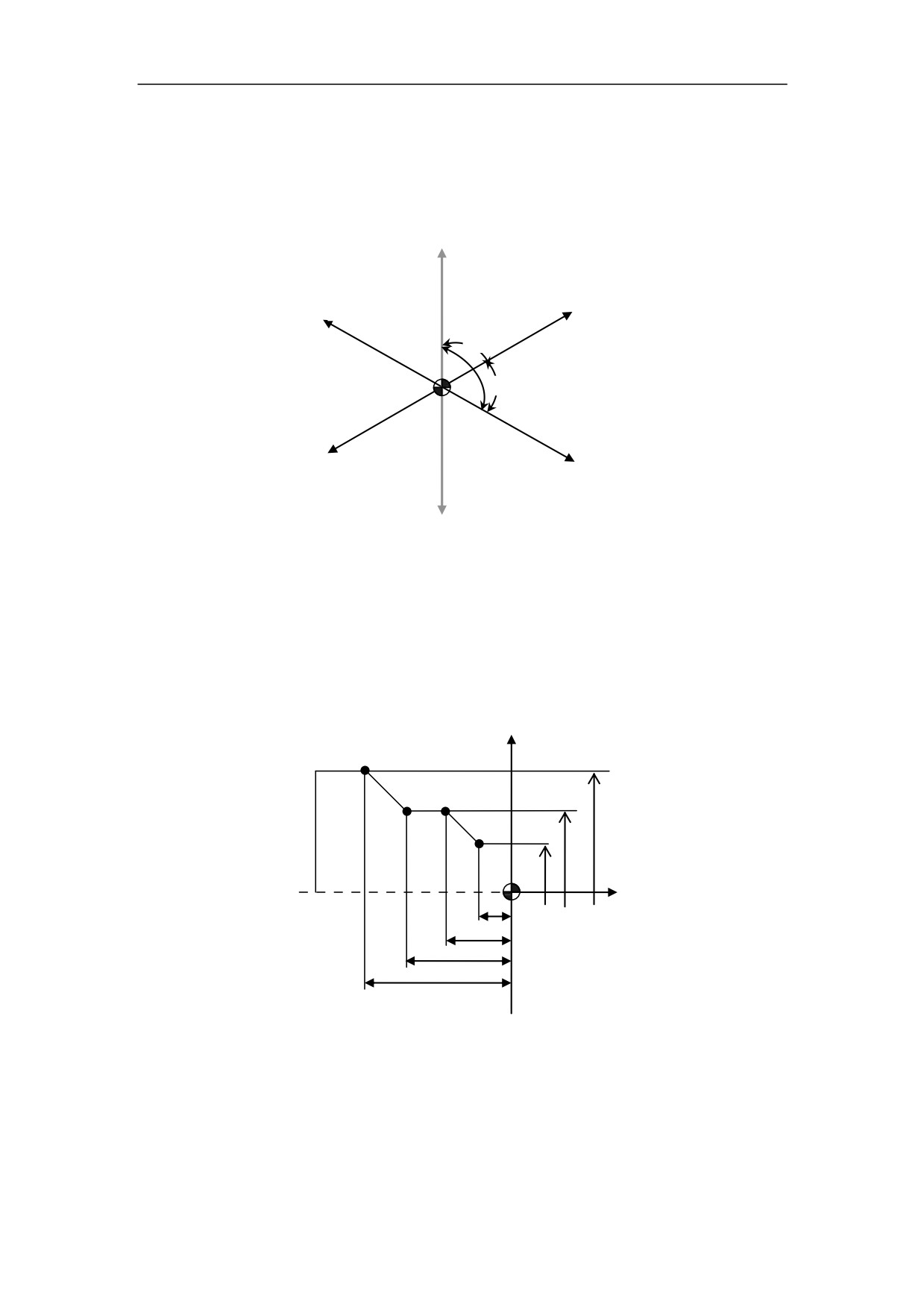
The coordinate system is set on a workpiece. The data in the NC program is from the
workpiece coordinate system.
Y+
Z-
X+
90°
Figure 1.10 Workpiece Coordinate System
Example: Those four points can be defined on workpiece coordinate system:
P1 corresponds to X25 Z-7.5
P2 corresponds to X40 Z-15
P3 corresponds to X40 Z-25
P4 corresponds to
X60 Z-35
X
P4
P3 P2
Φ60
P1
Φ40
Φ25
7.5
Z
15
25
35
Figure 1.11 Example of defining points on workpiece coordinate system
9
1. General
1.4.4 Setting Two Coordinate Systems at the Same Position
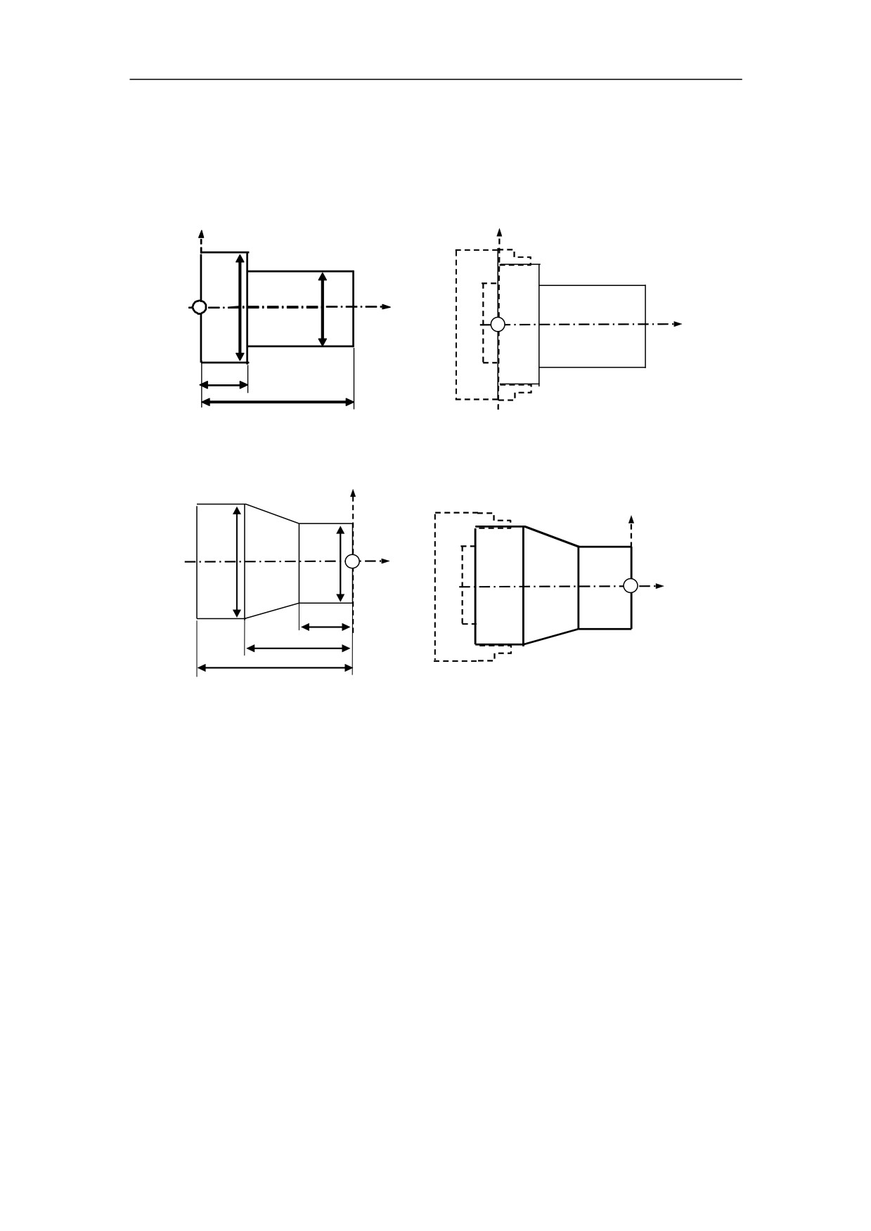
There are two methods used to define two coordinate systems at the same position.
1)
The coordinate zero point is set at chuck face
X
X
40
150
Figure 1.12 The coordinate zero point set at chuck face
2)
The coordinate zero point is set at the end face of workpiece
X
X
30
80
100
Figure 1.13 The coordinate zero point set at the end face of workpiece
10
1. General
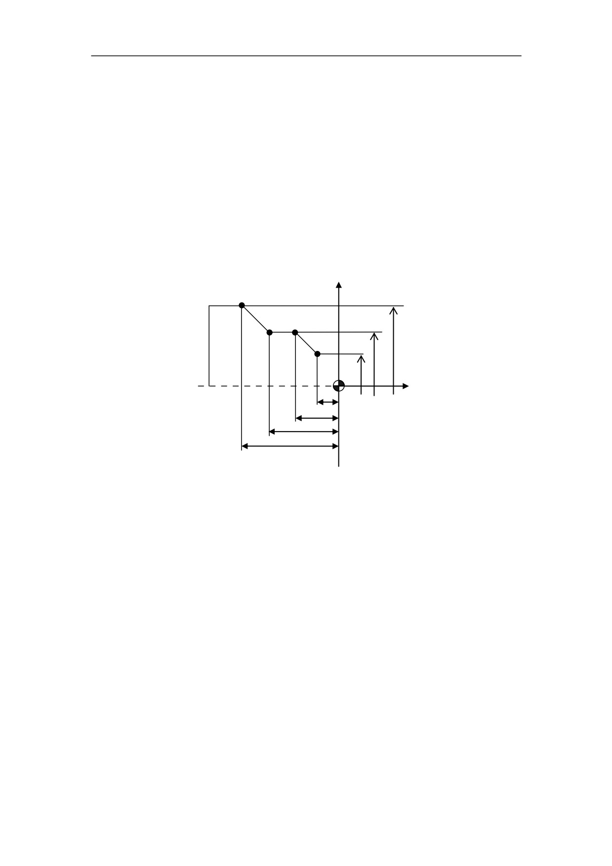
1.4.5 Absolute Commands
The absolute dimension describes a point at “the distance from zero point of the
coordinate system”.
Example: These four point in absolute dimensions are the following:
P1 corresponds to X25 Z-7.5
P2 corresponds to X40 Z-15
P3 corresponds to X40 Z-25
P4 corresponds to X60 Z-35
X
P4
P3 P2
Φ60
P1
Φ40
Φ25
7.5
Z
15
25
35
Figure 1.14 Absolute Dimension
11
1. General
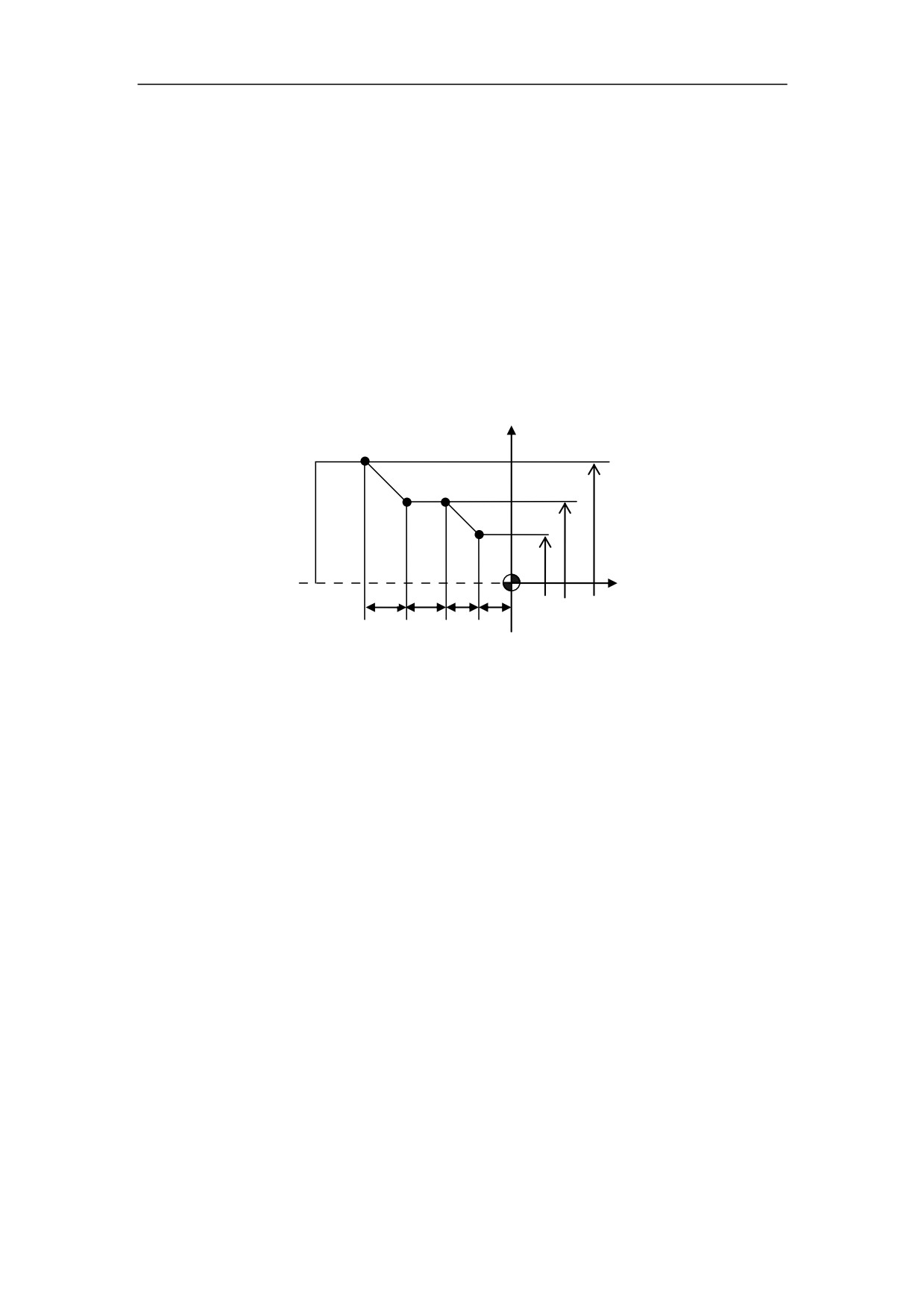
1.4.6 Incremental Commands
The incremental dimension describes a distance from the previous tool position to the
next tool position.
Example: These four point in incremental dimensions are the following:
P1 corresponds to X25 Z-7.5
//with reference to the zero point
P2 corresponds to X15 Z-7.5
//with reference to P1
P3 corresponds to Z-10
//with reference to P2
P4 corresponds to X20 Z-10
//with reference to P3
X
P4
P3 P2
Φ60
P1
Φ40
Φ25
10
7.5
7.5
Z
Figure 1.15 Incremental Dimension
12
1. General
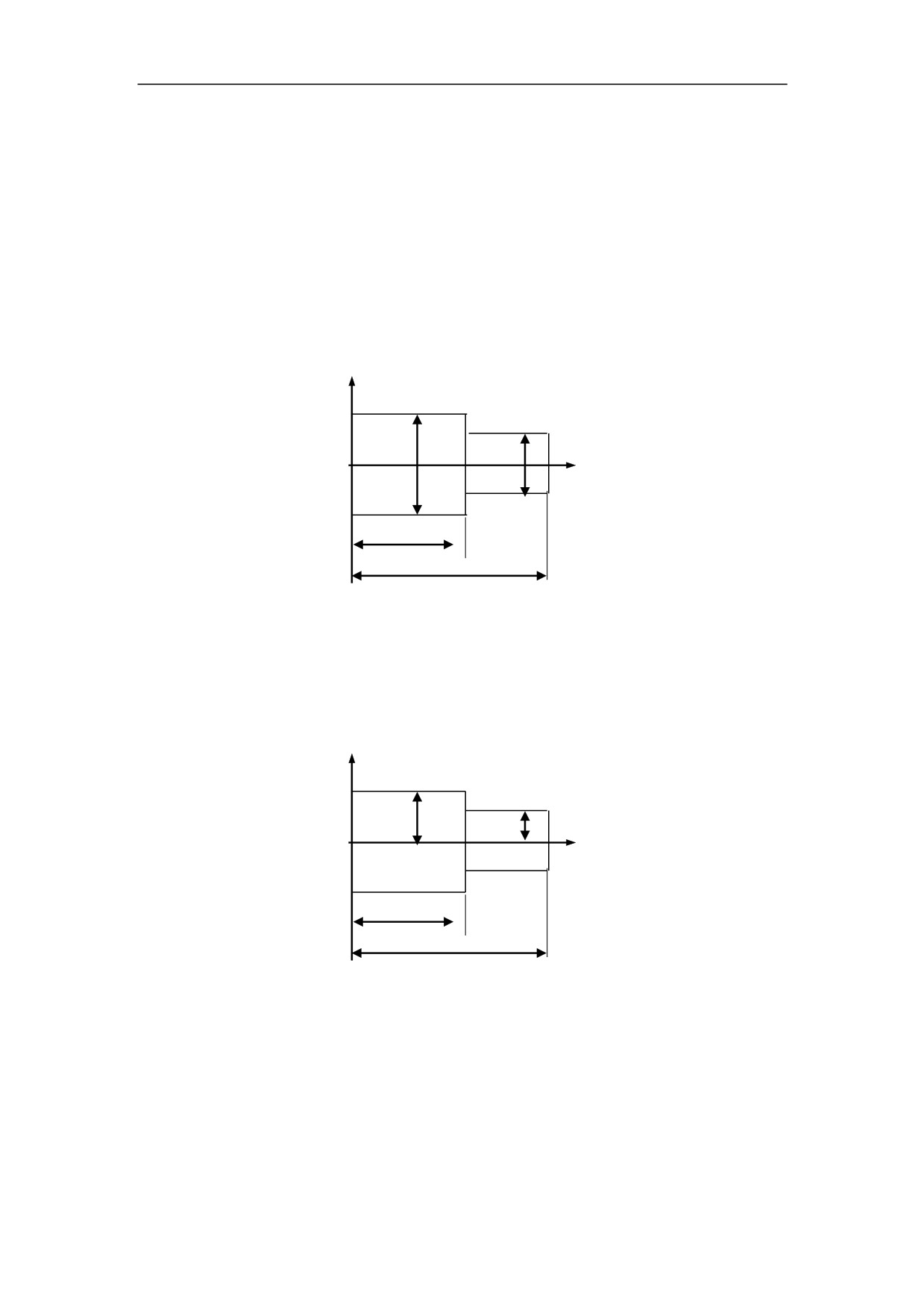
1.4.7 Diameter/Radius Programming
The coordinate dimension on X axis can be set in diameter or radius. It should be
noted that diameter programming or radius programming should be applied
independently on each machine.
Example: Describe the points by diameter programming.
A corresponds to X30 Z80
B corresponds to X40 Z60
X
B
A
Z
60
80
Figure 1.16 Diameter Programming
Example: Describe the points by radius programming.
A corresponds to X15 Z80
B corresponds to X20 Z60
X
B
A
Z
60
80
Figure 1.17 Radius Programming
13
1. General
1.5 Spindle Speed Function
Spindle speed function (s) is to control spindle rotation speed. The numerical value of
following S refers to spindle speed, and the unit of spindle speed is r/min.
The constant surface speed control refers to the specified cutting speed. The unit is
m/min (G96 starts constant surface speed, G97 constant surface speed is cancelled,
and G46 setting the limit of spindle speed).
S is modal command, i.e. Function S is effective until the another spindle speed is set.
The spindle speed can be set by the spindle override switch on NC control board.
14
1. General
1.6 Tool Function
1.6.1 Tool Selection
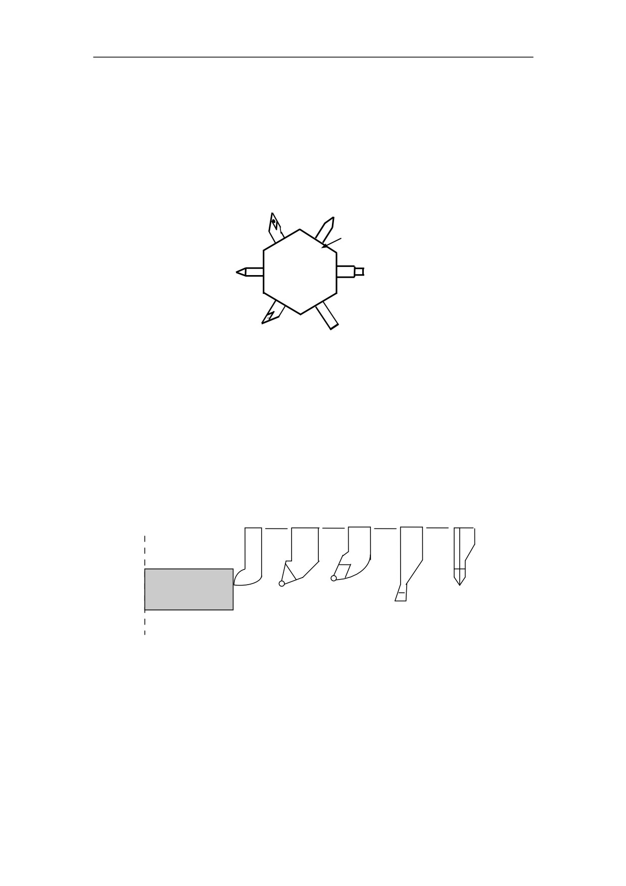
It is necessary to select a suitable tool when drilling, tapping, boring or the like is
performed. As it is shown in Figure 1.18, a number is assigned to each tool. Then this
number is used in the program to specify that the corresponding tool is selected.
Tool number
01
06
02
05
Tool post
03
04
Figure 1.18 Tool Selection
1.6.2 Tool Offset
When writing a program, the operator just use the workpiece dimensions according to
the dimensions in the part drawing. The tool nose radius center, the tool direction of
the turning tool, and the tool length are not taken into account. However, when
machining a workpiece, the tool path is affected by the tool geometry.
Rough
Thread
Standard
cutting
Finishing Grooving cutting
tool
tool
tool
tool
tool
workpiece
Figure 1.19 Tool Offset
15
1. General
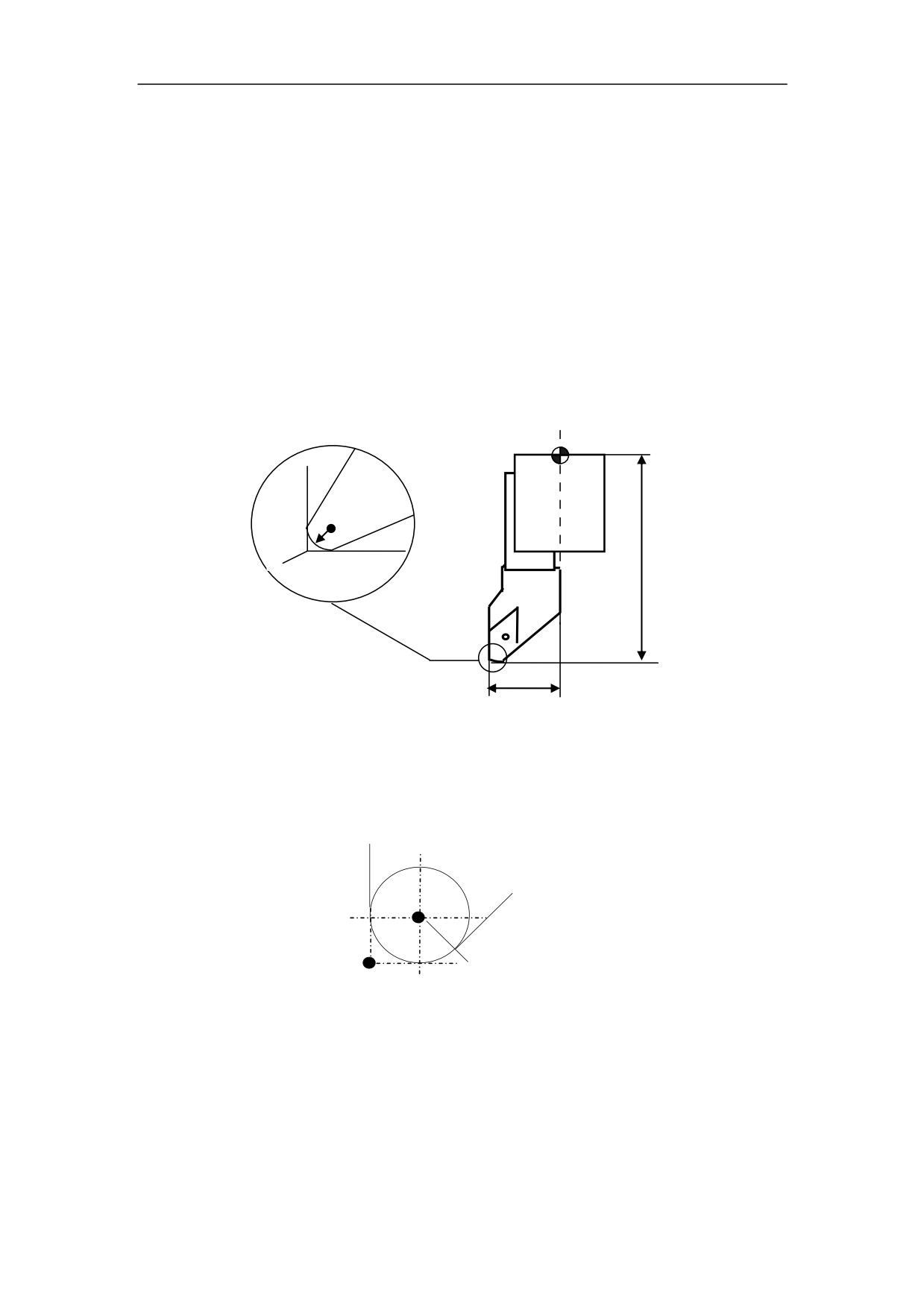
z Tool Length Compensation
There are two kind of ways to specify the value of tool length compensation.
-
Absolute value of tool length compensation (the distance between tool tip and
machine reference point)
-
Incremental value of tool length compensation (the distance between tool tip
and the standard tool)
As it is shown in Figure 1.20, L1 is the tool length on X axis. L2 is the tool length on Z
axis. It should be noted that the tool wear values on X axis or Z axis are also
contained in the tool length compensation.
R S
P=Tool tip
R=Radius
S=Cutting edge center
L2
Figure 1.20 Tool Length Compensation
z Tool Radius Compensation
Figure 1.21 shows the imaginary tool nose as a start position when writing a program.
P
Tool nose radius center
Imaginary tool nose
Figure 1.21 The imaginary tool nose
16
1. General
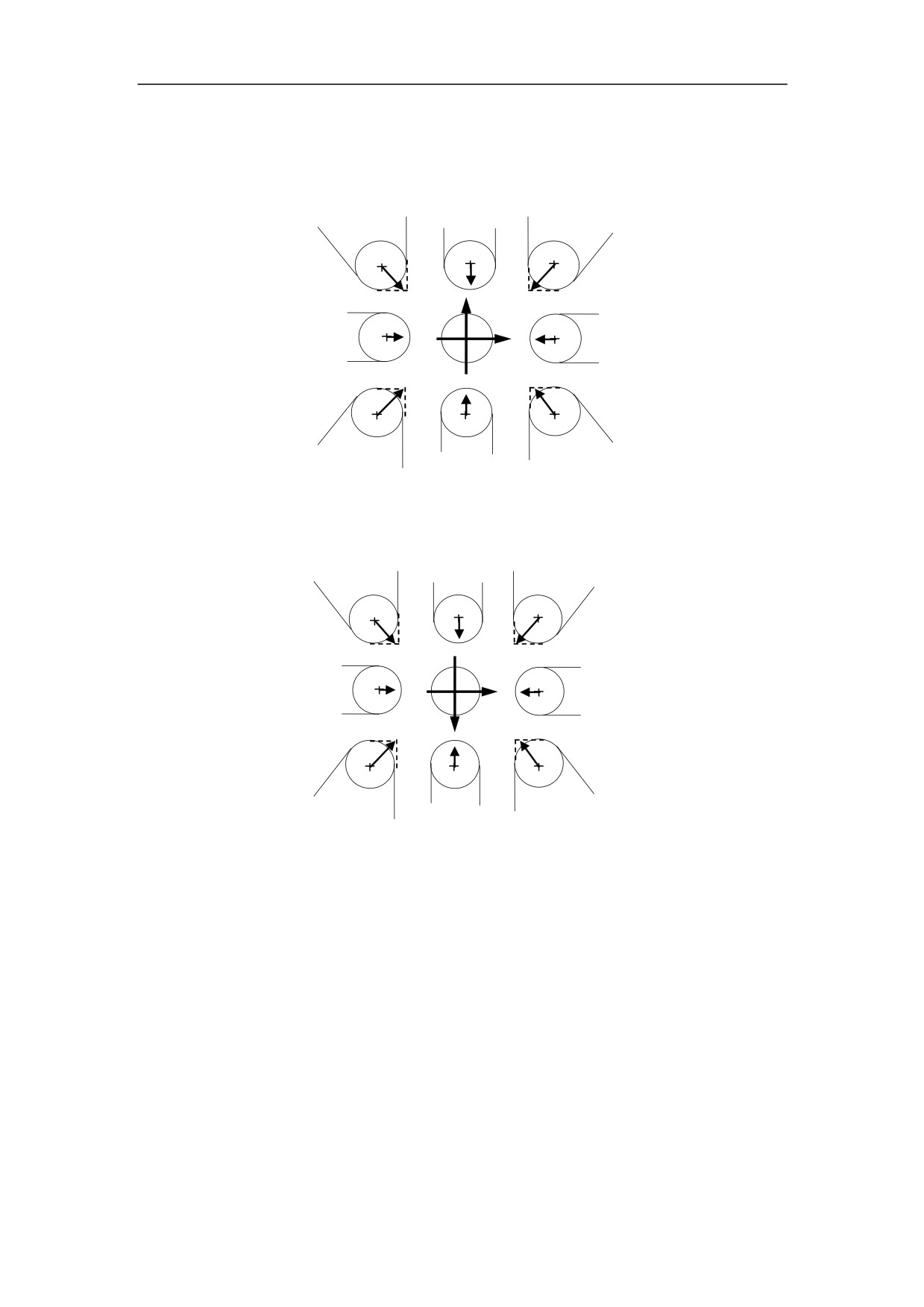
The direction of imaginary tool nose is determined by the tool direction during cutting.
Figure 1.22 and Figure 1.23 show the relation between the tool and the imaginary tool
tip.
4
8
3
●
●
●
Z
5
0
9
7
●
●
●
X
●
●
●
1
6
2
● Imaginary tool nose
+ Tool nose radius center
Figure 1.22 The direction of imaginary tool nose (1)
1
6
2
●
●
●
Z
5
0
9
7
●
●
●
X
●
●
●
4
8
3
● Imaginary tool nose
+ Tool nose radius center
Figure 1.23 The direction of imaginary tool nose (2)
17
1. General
1.7 Miscellaneous Function
Miscellaneous function refers to the operation to control the spindle, feed, and coolant.
In general, it is specified by an M code.
When a move command and M code are specified in the same block, there are two
ways to execute these commands:
1) Pre-M function
M command is executed before the completion of move command
2) Post-M function
M command is executed after the completion of move command.
The sequence of the execution depends on the specification of the machine tool
builder.
18
1. General
1.8 Program Configuration
1.8.1 Structure of an NC Program
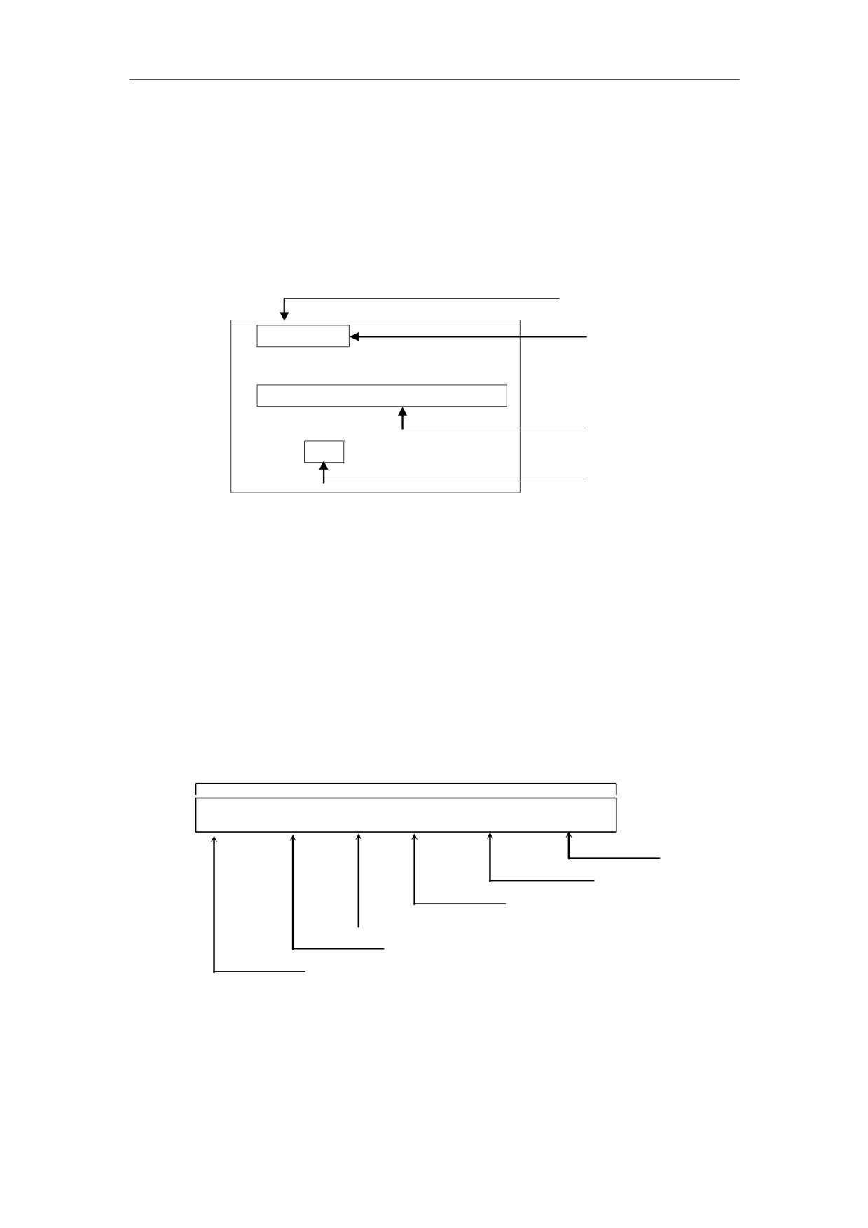
As it is shown in Figure 1.24, an NC program consists of a sequence of NC blocks.
Each block is one of machining steps. Commands in each block are the instruction.
Program
Program number
%1000
N01 G91 G00 X50 Y60
N10 G01 X100 Y500 F150 S300 M03
Program block
N
;COMMENT
N200
M30
Command character
Figure 1.24 Structure of an NC Program
-
Format of program name
The program name must be specified in the format OXXXX (X could be letters or
numbers).
-
Format of program number
The program number should be started with %XXXX or OXXXX (X could be
numbers only).
-
Format of blocks
A block starts with the program block number.
Program block
N..
G..
X…Y… F..
M..
S..
Spindle function
Miscellaneous function
Feed Function
Coordinate - Dimension word
Preparatory function
Program block number
Figure 1.25 Structure of Block
19
1. General
-
Format of end of program
The last block should contain M02 or M03 to indicate the end of program.
-
Format of Comments
All information after the “;” is regarded as comments.
All information between “( )” is regarded as comments.
1.8.2 Main Program and Subprogram
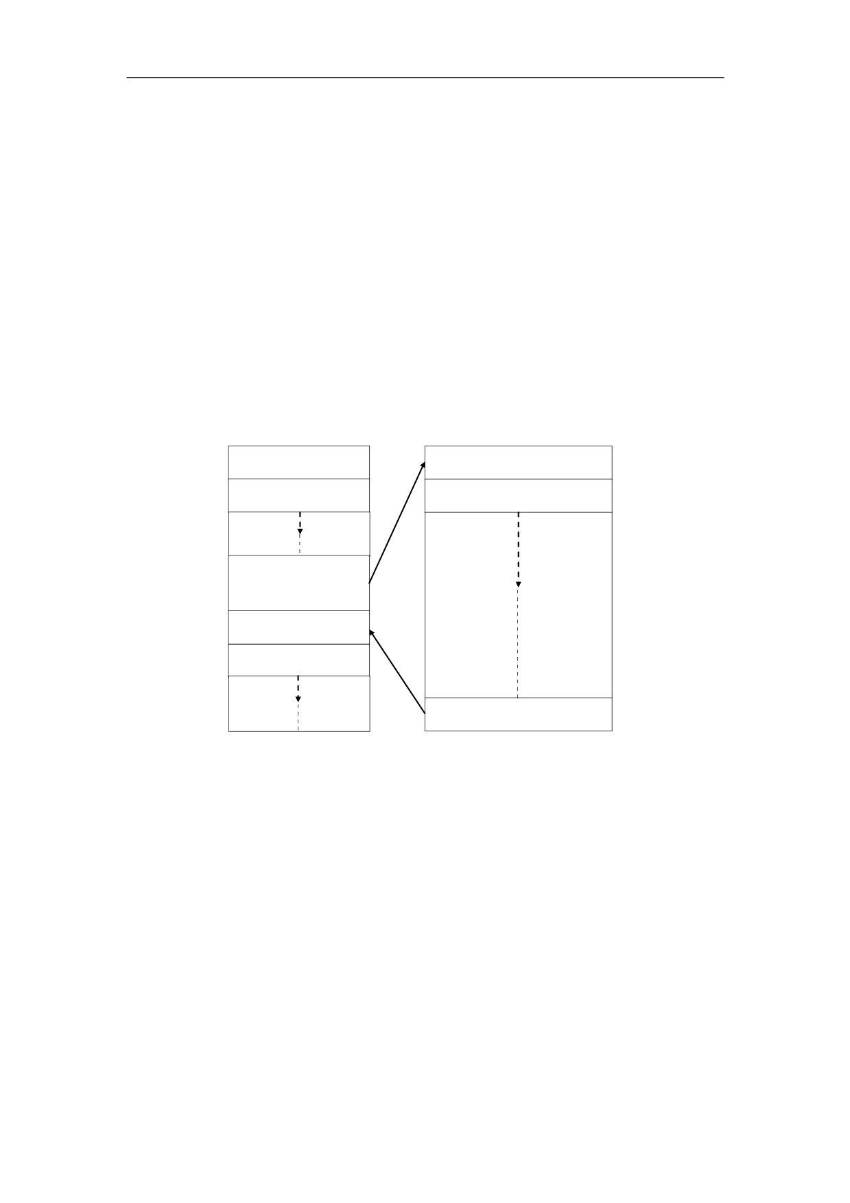
There are two type of program: main program and subprogram. The CNC operates
according to the main program. When a execution command of subprogram is at the
execution line of the main program, the subprogram is called. When the execution of
subprogram is finished, the system returns control to the main program.
Main program
Subprogram
Instruction 1
Instruction 1
Instruction 2
Instruction 2
Follow the direction
ofthe subprogram
Instruction n
Instruction n+1
Return to the main program
Figure 1.26 Main program and subprogram
Note:
Main program and its subprogram must be written in a same file with a different
program codes.
20
2. Preparatory Function
2 Preparatory Function (G code)
There are two types of G code: one-shot G code, and modal G code.
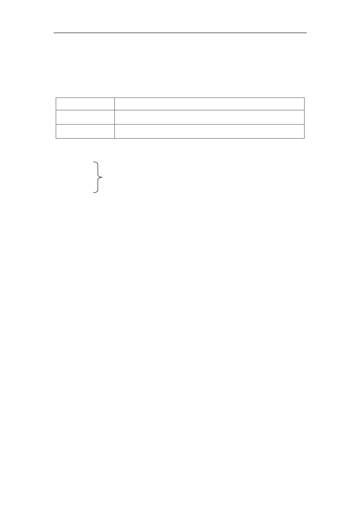
Table 2-1 Type of G code
Type
Meaning
One-shot G code
The G code is only effective in the block in which it is specified
Modal G code
The G code is effective until another G code is specified.
Example: G01 and G00 are modal G codes.
G00X_
Z_
G00 is effective in this range
X_
G01Z_
21
2. Preparatory Function
2.1 G code List
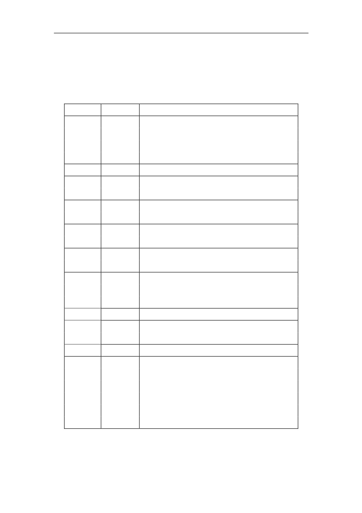
The following table is the list of G code in HNC system.
Table 2-2 G code list
G code
Group
Function
G00
Positioning (Rapid traverse)
◣G01
Linear interpolation (Cutting feed)
01
G02
Circular interpolation CW
G03
Circular interpolation CCW
G04
00
Dwell
G20
Input in inch
08
◣G21
Input in mm
G28
Reference point return
00
G29
Auto return from reference point
G32
Thread cutting with constant lead
01
G34
Tapping
◣G36
Diameter programming
17
G37
Radius programming
◣G40
Tool nose radius compensation cancel
G41
09
Tool nose radius compensation on the left
G42
Tool nose radius compensation on the right
G46
16
Setting the limit of spindle speed
◣G50
Canceling the workpiece’s origin movement
04
G51
Moving the origin of workpiece coordinate system
G53
00
Selecting a machine coordinate system
◣G54
G55
G56
11
Setting a workpiece coordinate system
G57
G58
G59
22
2. Preparatory
Function
G71
Stock Removal in Turning
G72
Stock Removal in Facing
G73
Pattern repeating
G74
Front drilling cycle
G75
06
Side drilling cycle
G76
Multiple thread cutting cycle
G80
Internal diameter/Outer diameter cutting cycle
G81
End face turning cycle
G82
Thread cutting cycle
◣G90
Absolute programming
13
G91
Incremental programming
G92
00
Setting a coordinate system
◣G94
Feedrate per minute
14
G95
Feedrate per revolution
G96
Constant cutting speed starts
16
◣G97
Constant cutting speed is cancelled
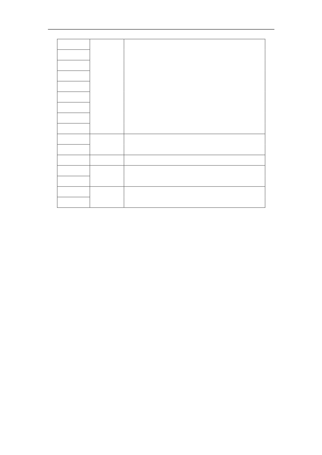
Explanation:
1) G codes in 00 group are one-shot G code, while the other groups are modal
G code.
2)
◣ means that it is default setting.
23
3. Interpolation Function
3 Interpolation Functions
This chapter would introduce:
1) Positioning Command (G00)
2) Linear Interpolation (G01)
3) Circular Interpolation (G02, G03)
4) Chamfering and Rounding (G01, G02, G03)
5) Thread Cutting with Constant Lead (G32)
6) Tapping (G34)
7) Direct Drawing Dimension Programming (G01)
24
3. Interpolation Function
3.1 Positioning (G00)
Programming
G00 X(U)… Z(W)…
Explanation of the parameters
X, Z
Coordinate value of the end point in the absolute command
U, W Coordinate value of the end point in the incremental command
Function
The tool is moved at the highest possible speed (rapid traverse). If the rapid traverse
movement is required to execute simultaneously on several axes, the rapid traverse
speed is decided by the axis which takes the most time. The operator can use this
function to position the tool rapidly, to travel around the workpiece, or to approach the
tool change position.
Example
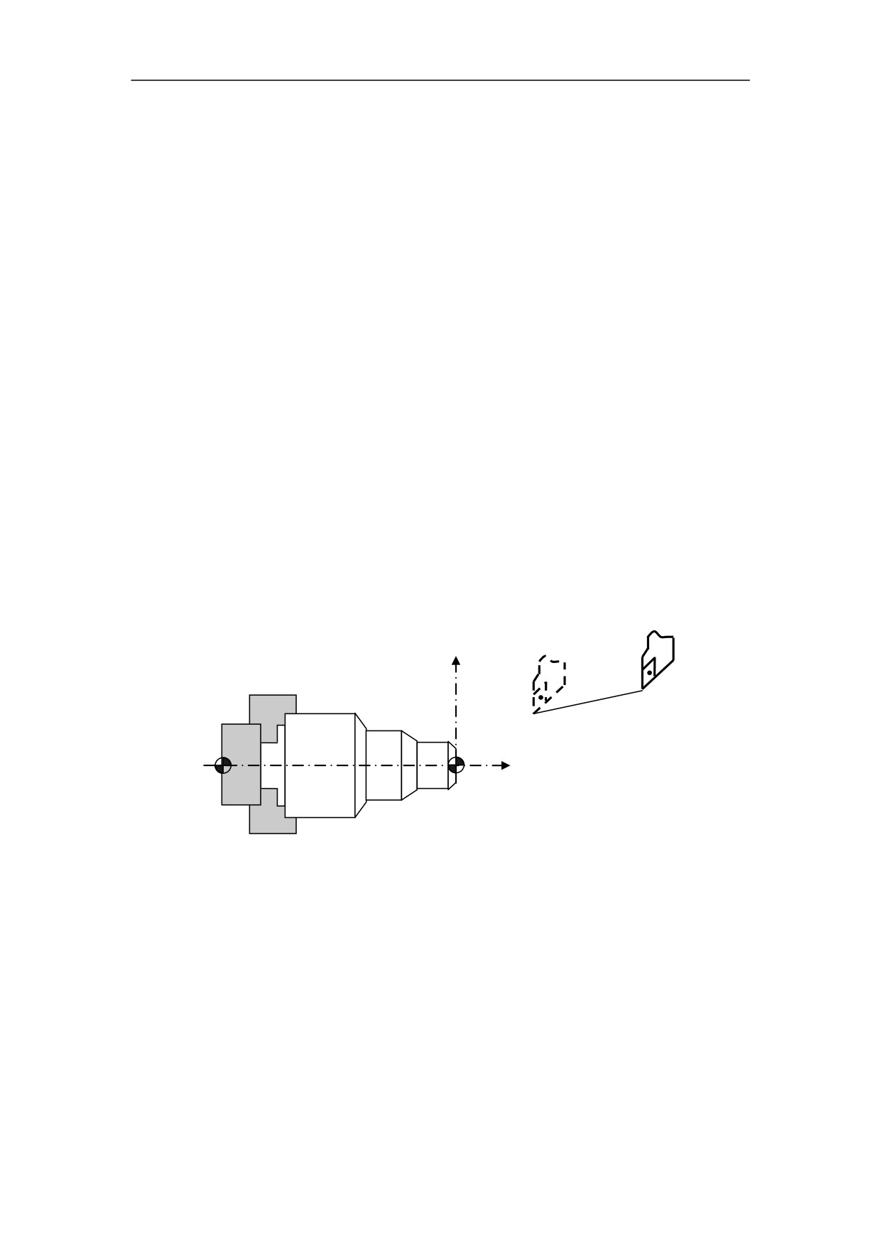
Move tool from P1 (45, 90) to P2 (10, 20) at the rapid traverse speed.
X
P1
P2
M
W
Z
Figure 3.1 Positioning (Rapid Traverse)
Absolute programming:
G00 X10 Z20
Incremental programming:
G00 U30 W70
25
//////////////////////