Century Star Turning CNC System. Programming Guide (V3.5 April, 2015) - page 2
3. Interpolation Function
3.2 Linear Interpolation (G01)
Programming
G01 X(U)… Z(W)… F…
Explanation of the parameters
X, Z
Coordinate value of the end point in the absolute command
U, W Coordinate value of the end point in the incremental command
F
Feedrate. It is effective until a new value is specified.
Function
The tool is moved along the straight line at the specified feedrate.
26
3. Interpolation Function
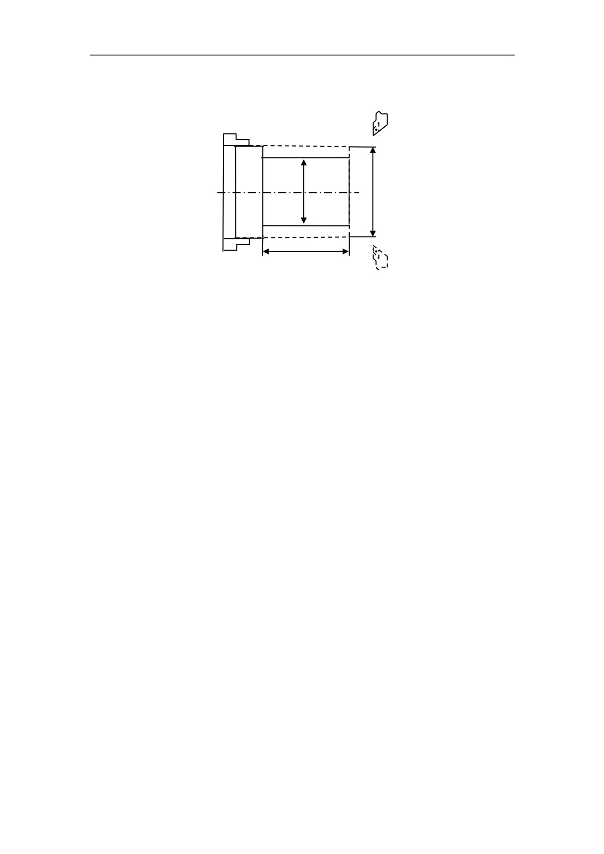
Example 1
Use G01 command to rough machining and finish machining the simple cylinder part.
50
Figure 3.2 Linear Interpolation - Example 1
%3306(Absolute command)
%3306(Incremental command)
N1 T0106
N1 T0101
N2 M03 S460
N2 M03 S460
N3 G00 X90Z20
N3 G00 X90Z20
N4 G00 X31Z3
N4 G00 X31Z3
N5 G01 Z-50 F100
N5 G01 W-53 F100
N6 G00 X36
N6 G00 U5
N7 Z3
N7 W53
N8 X30
N8 U-6
N9 G01 Z-50 F80
N9 G01 Z-50 F80
N10 G00 X36
N10 G00 X36
N11 X90 Z20
N11 X90 Z20
N12 M05
N12 M05
N13 M30
N13 M30
27
3. Interpolation Function
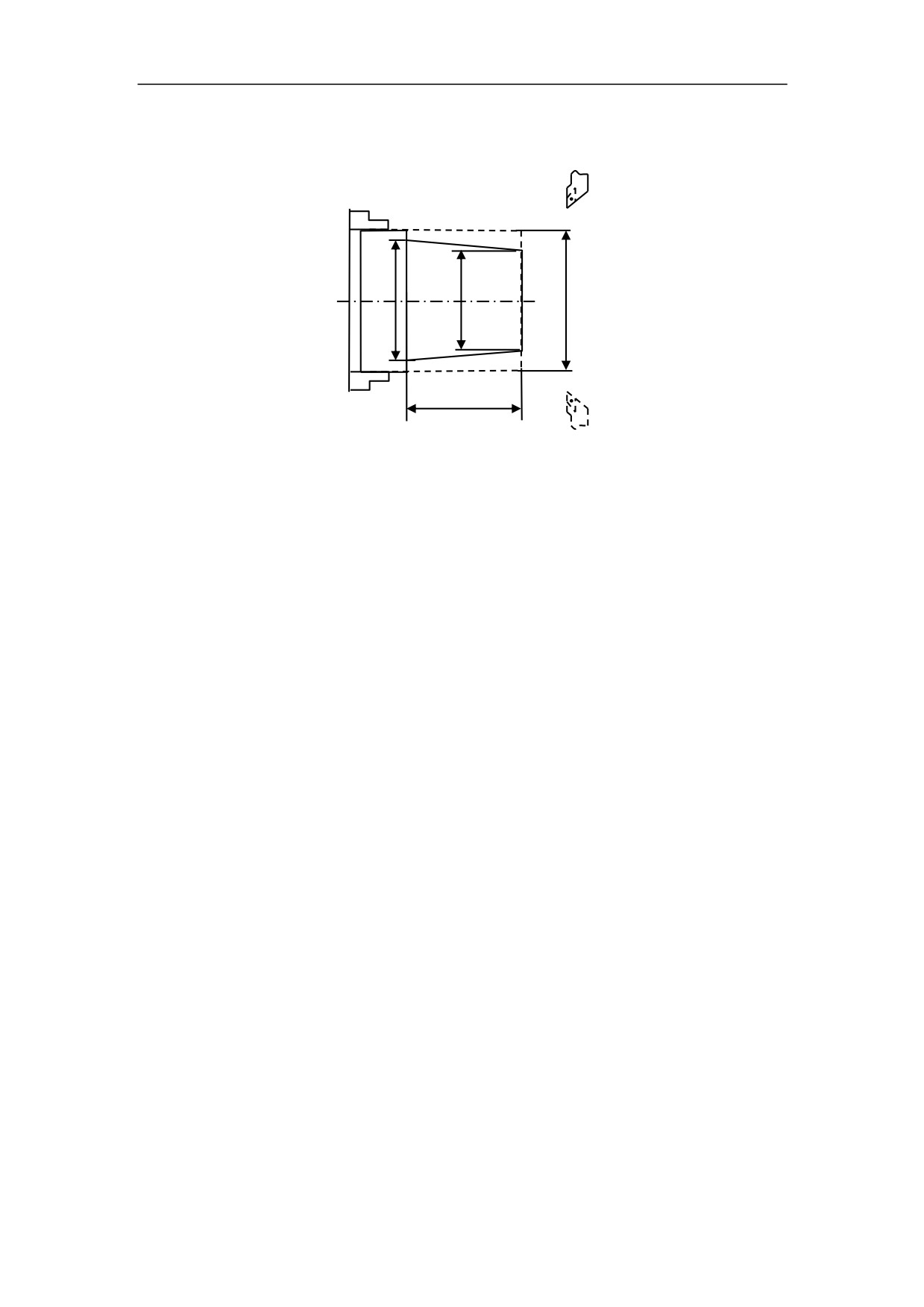
Example 2
Use G01 command to rough machining and finish machining simple conical part.
50
Figure 3.3 Linear Interpolation - Example 2
%3307
N1 T0101
N2 M03 S460
N3 G00 X100Z40
N4 G00 X26.6 Z5
N5 G01 X31 Z-50 F100
N6 G00 X36
N7 X100 Z40
N8 T0202
N9 G00 X25.6 Z5
N10 G01 X30 Z-50 F80
N11 G00 X36
N12 X100 Z40
N13 M05
N14 M30
28
3. Interpolation Function
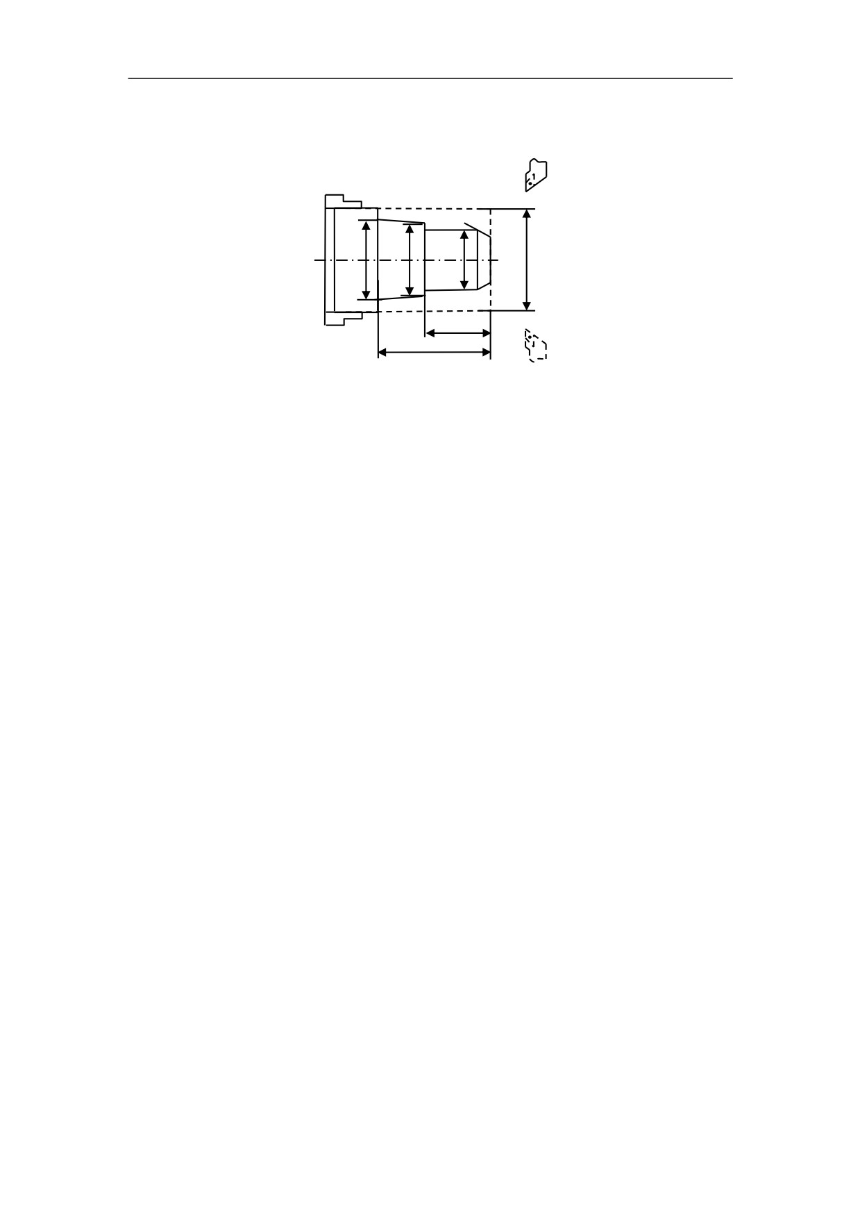
Example 3
Use G01 command to rough machining and finish machining the part.
2×45°
20
50
Figure 3.4 Linear Interpolation - Example 3
%3308
N1 T0101
N2 M03 S450
N3 G00 X100 Z40
N4 G00 X31 Z3
N5 G01 Z-50 F100
N6 G00 X36
N7 Z3
N8 X25
N9 G01 Z-20 F100
N10 G00 X36
N11 Z3
N12 X15
N13 G01 U14 W-7 F100
N14 G00 X36
N15 X100 Z40
N16 T0202
N17 G00 X100Z40
N18 G00 X14 Z3
N19 G01 X24 Z-2 F80
N20 Z-20
N21 X28
N22 X30 Z-50
N23 G00 X36
N24 X80 Z10
N24 M05
N25 M30
29
3. Interpolation Function
3.3 Circulation Interpolation (G02, G03)
Programming
G02
I_K_
X(U)_Z(W)
_
F_
G03
R_
Explanation of the parameters
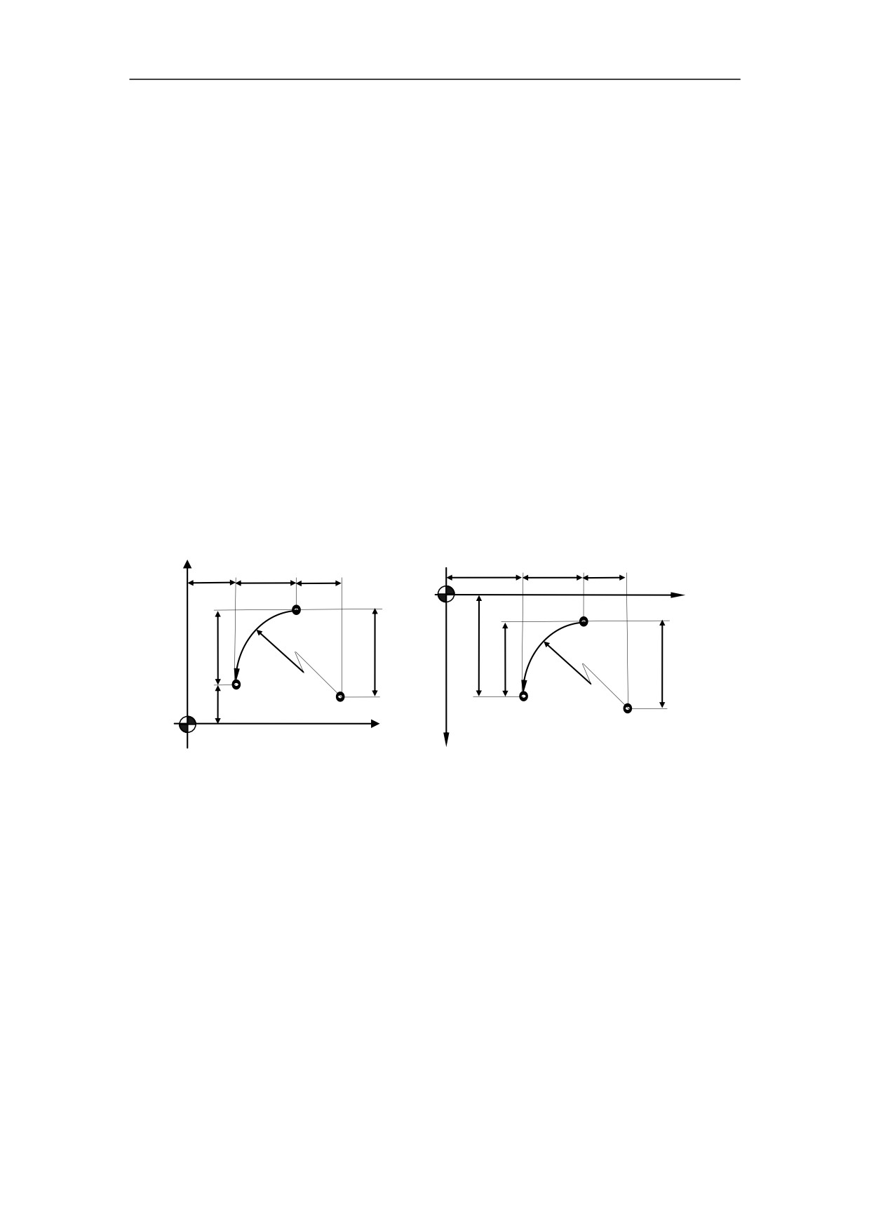
G02 a circular path in clockwise direction (CW)
G03 a circular path in counterclockwise direction (CCW)
X, Z
Coordinate values of the circle end point in absolute command
U, W Coordinate values of the circle end point with reference to the circle starting
point in incremental command.
I, K
Coordinate values of the circle center point with reference to the circle
starting point in incremental command.
R
Circle radius. R is valid when I, K, R are all specified in this command.
F
Feedrate
+X
z
w
k
z
w
k
+Z
A
A
R
u/2
i
R
x/2
u/2
i
B
B
x/2
Circle center point
Circle center point
+X
+Z
Figure 3.5 Description of G02/G03 parameter
30

3. Interpolation Function
G02 and G03 are defined when the working plane is specified. Figure 3.6 shows the
direction of circular interpolation.
+X
G03
G03
G02
G02
G02
G02
G03
G03
+Y
+Z
+Y
+Z
G02
G02
G03
G03
G03
G03
G02
+X
G02
Figure 3.6 Direction of Circular Interpolation
Function
The tool is moved along a full circle or arcs.
31
3. Interpolation Function
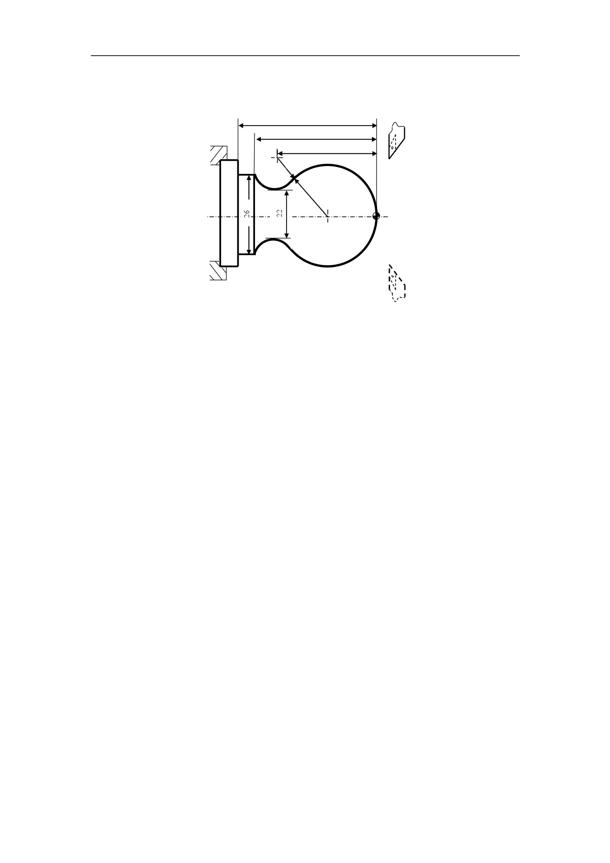
Example 1
Use the circular interpolation command to program
40
31
27
R15
Figure 3.7 Circular Interpolation - Example 1
%3309
N1 T0101
N2 G00 X40 Z5
N3 M03 S400
N4 G00 X0
N5 G01 Z0 F60
N6 G03 U24 W-24 R15
N7 G02 X26 Z-31 R5
N8 G01 Z-40
N9 X40 Z5
N10 M30
32
3. Interpolation Function
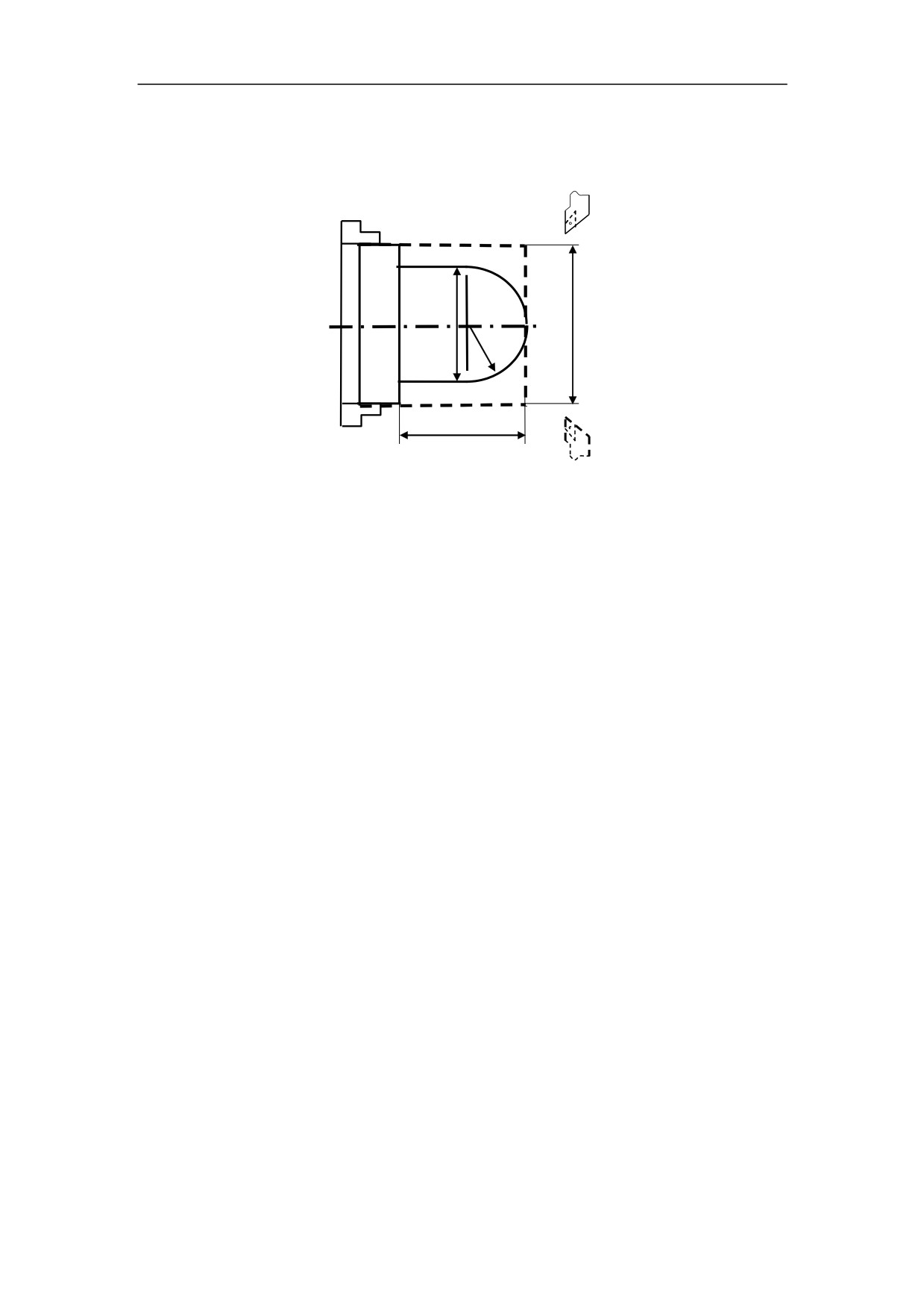
Example 2
Use the circular interpolation command to program
R15
35
Figure 3.8 Circular Interpolation - Example 2
%3310(Absolute programming)
N4 G00 U-90 W-17
N5 G01 W-3 F100
N1 T0101
N6 G03 U30 W-15 R15
N2 M03 S460
N7 G01 W-20
N3 G00 X90Z20
N8 X36
N4 G00 X0 Z3
N9 G00 X90 Z20
N5 G01 Z0 F100
N10 M05
N6 G03 X30 Z-15 R15
N11 M30
N7 G01 Z-35
N8 X36
N9 G00 X90 Z20
N10 M05
N11 M30
%3310(Incremental
programming)
N1 T0101
N2 M03 S460
N3 G00 X90Z20
33
3. Interpolation Function
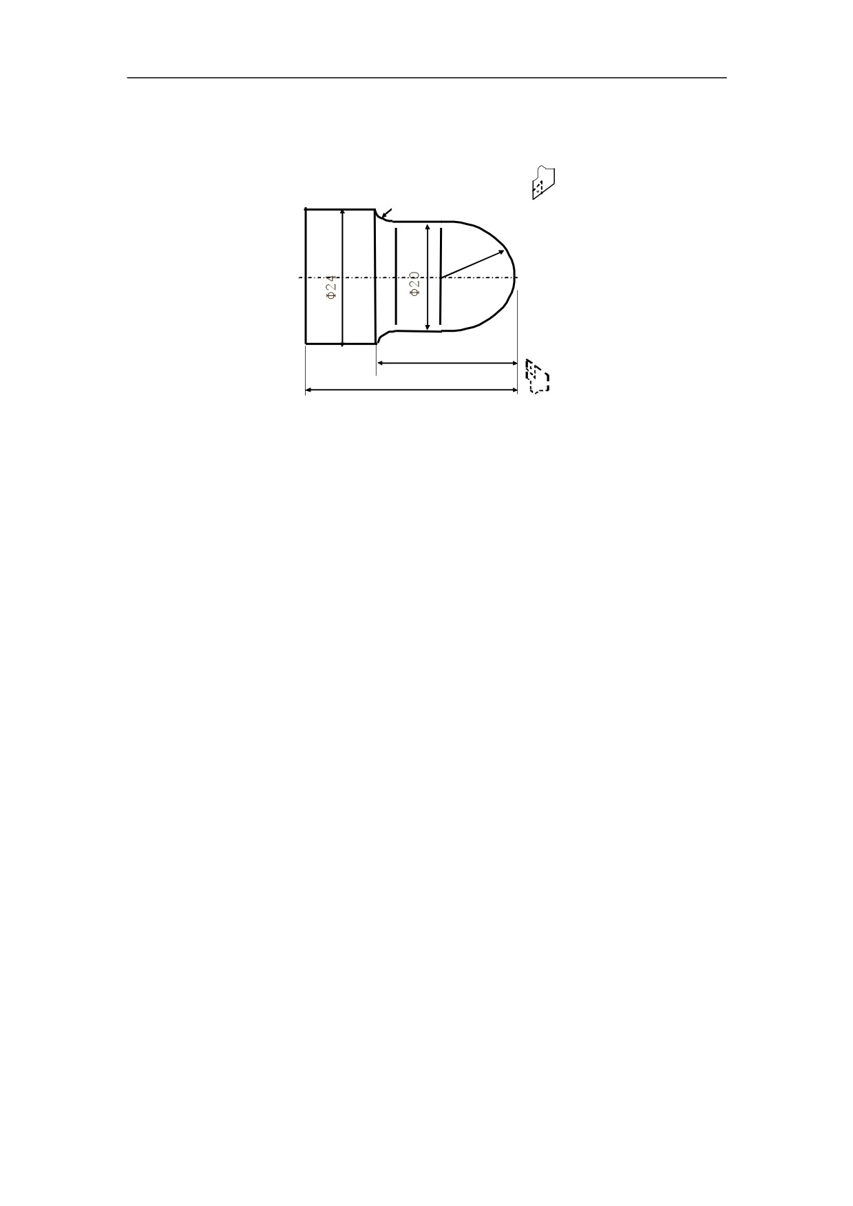
Example 3
Use the circular interpolation command to program.
R4
R10
24
40
Figure 3.9 Circular Interpolation - Example 3
%3311
N1 T0101
N2 M03 S460
N3 G00 X100 Z40
N4 G00 X0 Z3
N5 G01 Z0 F100
N6 G03 X20 Z-10 R10
N7 G01 Z-20
N8 G02 X24 Z-24 R4
N9 G01 Z-40
N10 G00 X30
N11 X100 Z40
N12 M05
N13 M30
34
3. Interpolation Function
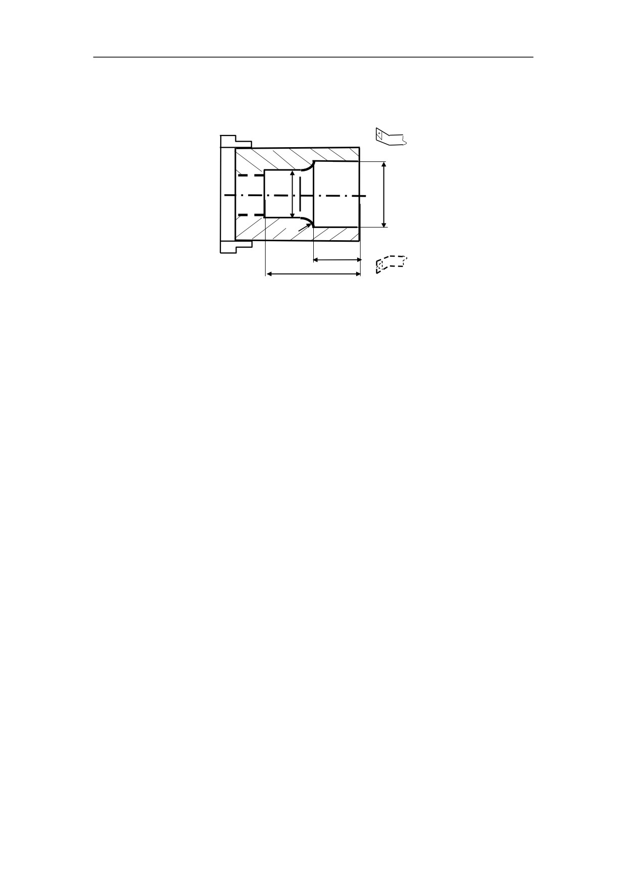
Example 4
Use the circular interpolation command to program
R2
20
40
Figure 3.10 Circular Interpolation - Example 4
%3312
N1 T0101
N2 M03 S460
N3 G00 X80 Z10
N4 G00 X30 Z3
N5 G01 Z-20 F100
N6 G02 X26 Z-22 R2
N7 G01 Z-40
N8 G00 X24
N9 Z3
N10 X80 Z10
N11 M05
N12 M30
35
3. Interpolation Function
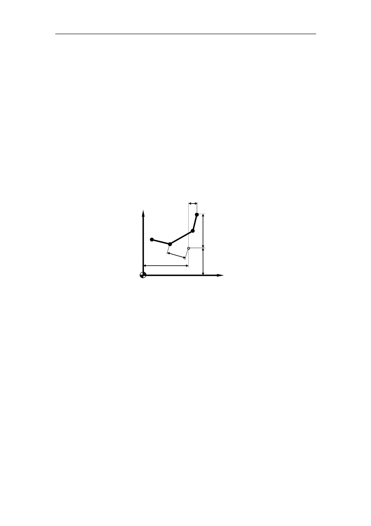
3.4 Chamfering and Rounding (G01, G02, G03)
Note: These commands cannot be used in thread cutting.
3.4.1 Chamfering (G01)
Programming
G01 X(U)_ Z(W)_ C_
Explanation of the parameters
X, Z
Coordinate values of the intersection (point G) in absolute command
U, W Coordinate values of the intersection (point G) in incremental command
C
Width of chamfer in original direction of movement (c)
w
+X
A
D
u/2
B
C
1.
1.
c
G
z
x/2
+Z
Figure 3.11 Chamfering (G01)
Function
A chamfer can be inserted between two blocks which intersect at a right angle (point
A→B→C).
Note: The length of GA should be more than the length of GB
36
3. Interpolation Function
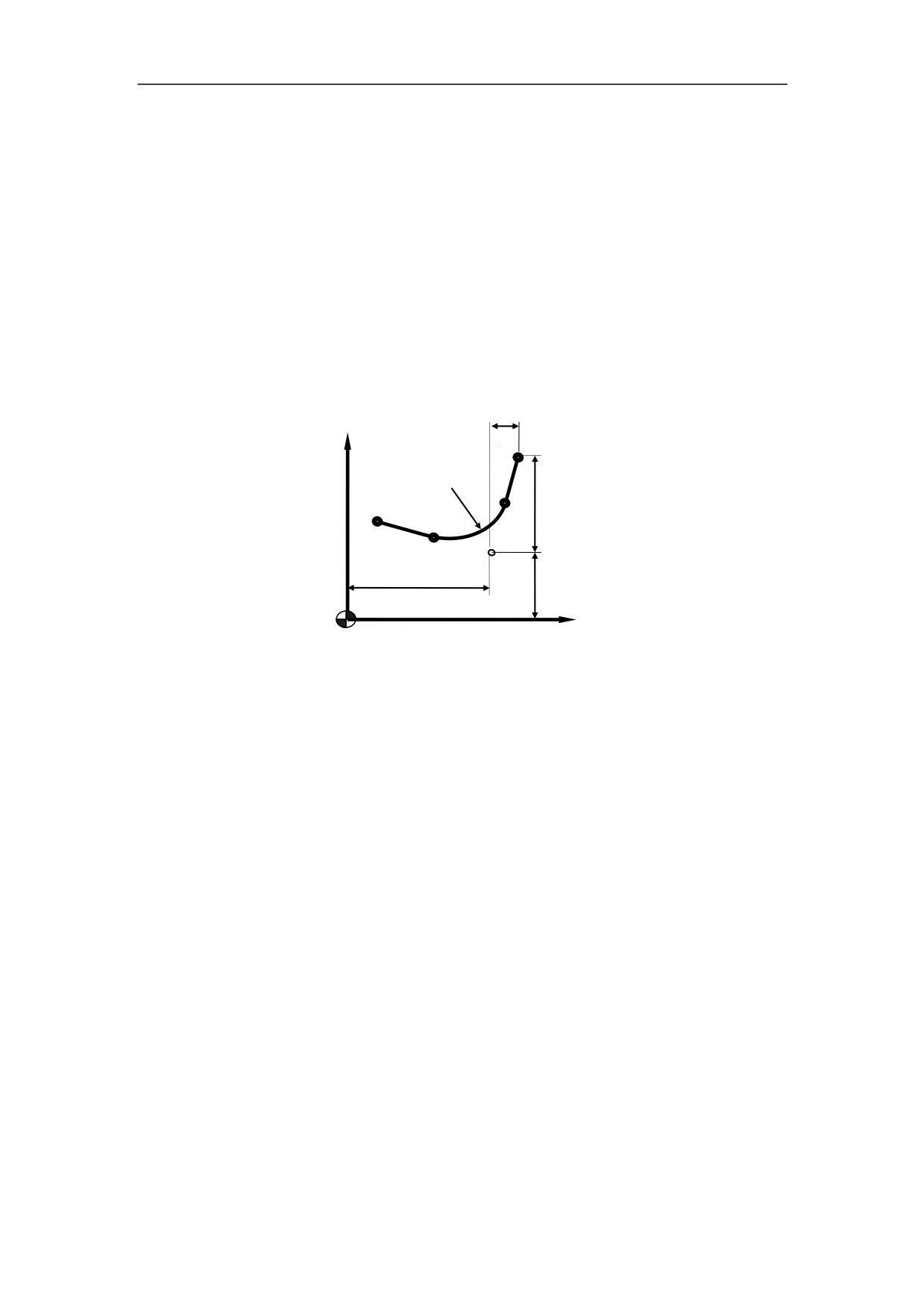
3.4.2 Rounding (G01)
Programming
G01 X(U)_ Z(W)_ R_
Explanation of the parameters
X, Z
Coordinate values of the intersection (point G) in absolute command
U, W Coordinate values of the intersection (pint G) in incremental command
R
Radius of the rounding (r)
+X
w
A
r
D
u
B
C
G
z
x
+Z
Figure 3.12 Rounding (G01)
Function
A corner can be inserted between two blocks which intersect at a right angle (point
A→B→C).
Note: The length of GA should be more than the length of GB
37
3. Interpolation Function
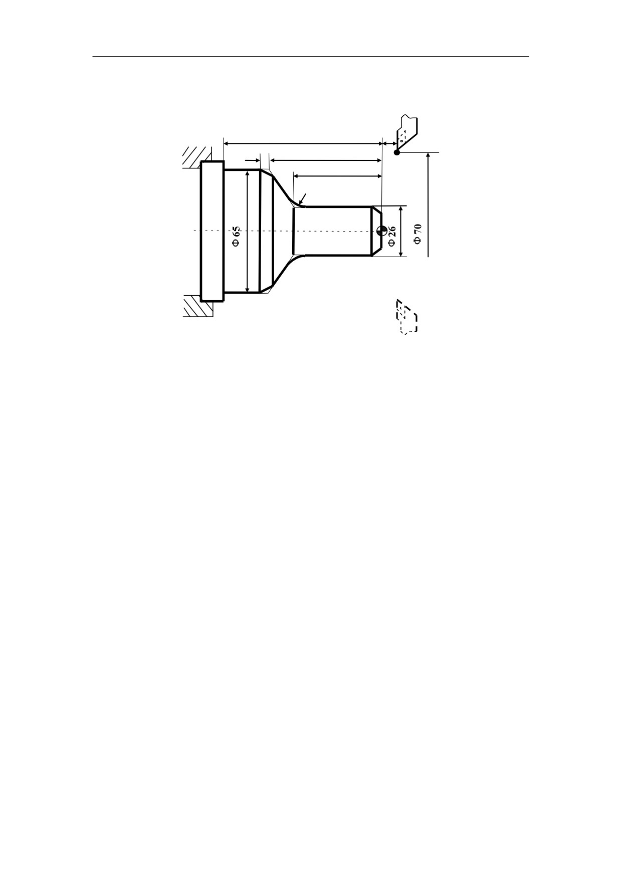
Example
Use the chamfering and rounding command (G01):
70
10
3
36
22
R3
Figure 3.13 Chamfering and Rounding (G01) - Example
%3314
N1 M03 S460
N2 G00 U-70 W-10
N3 G01 U26 C3 F100
N4 W-22 R3
N5 U39 W-14 C3
N6 W-34
N7 G00 U5 W80
N8 M30
38
3. Interpolation Function
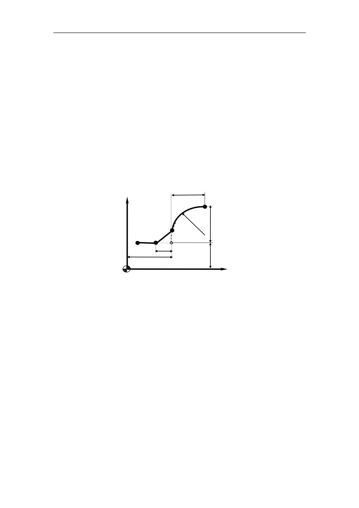
3.4.3 Chamfering (G02, G03)
Programming
G02
X(U)_ Z(W)_ R _ RL
_
G03
Explanation of the parameters
X, Z
Coordinate values of the intersection (point G) in absolute command
U, W Coordinate values of the intersection (point G) with reference to the circle
starting point (point A) in incremental command
R
Circle Radius (r)
RL= Width of chamfer in original direction of movement (RL)
w
+X
A
B
r
D C
RL=
G
z
+Z
Figure 3.14 Chamfering (G02/G03)
Function
A chamfer can be inserted between two blocks which intersect at a right angle (point
A→B→C).
Note: RL must be capitalized letters.
39
3. Interpolation Function
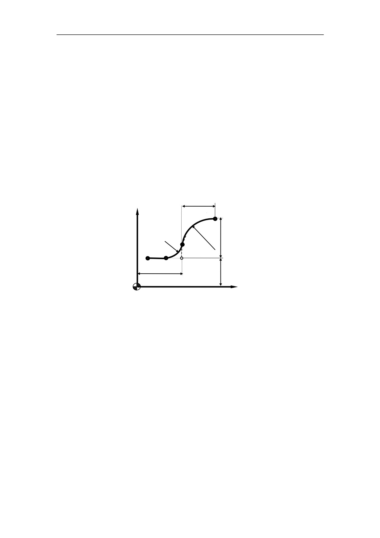
3.4.4 Rounding (G02, G03)
Programming
G02
X(U)_ Z(W)_ R _ RC
_
G03
Explanation of the parameters
X, Z
Coordinate values of the intersection (point G) in absolute command
U, W Coordinate values of the intersection (point G) with reference to the circle
starting point (point A) in incremental command
R
Circle radius (r)
RC Radius of rounding (rc)
+X
w
A
r
B
u
rc=
D
C
G
x/2
z
+Z
Figure 3.15 Rounding (G02/G03)
Function
A corner can be inserted between two blocks which intersect at a right angle (point
A→B→C).
Note: RC must be capitalized letters.
40
3. Interpolation Function
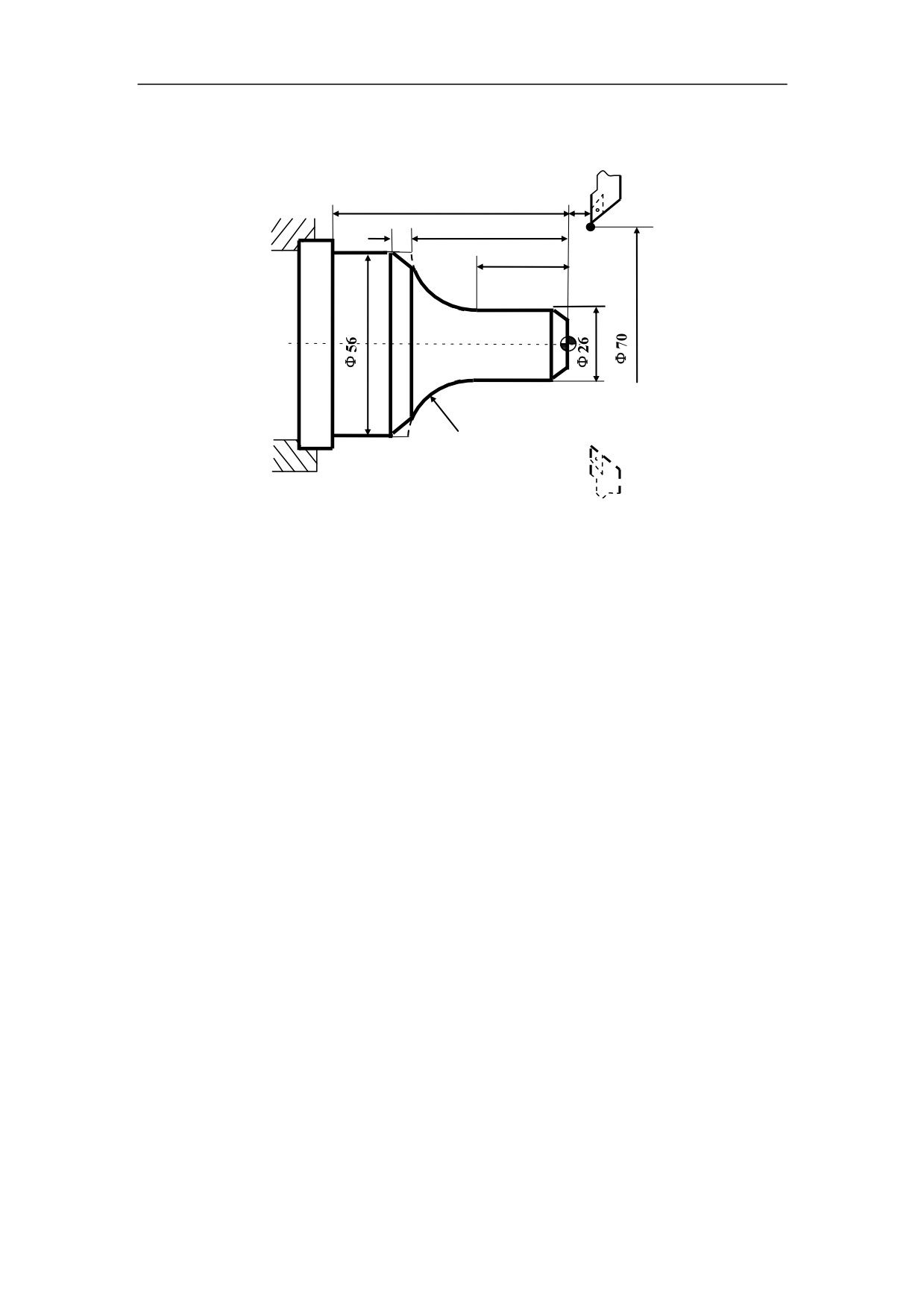
Example
Use the chamfering and rounding command (G02/G03):
70
10
4
36
21
R15
Figure 3.16 Chamfering and Rounding (G02/G03) - Example
%3315
N1 T0101
N2 G00 X70 Z10 M03 S460
N3 G00 X0 Z4
N4 G01 W-4 F100
N5 X26 C3
N6 Z-21
N7 G02 U30 W-15 R15 RL=4
N8 G01 Z-70
N9 G00 U10
N10 X70 Z10
N11 M30
41
3. Interpolation Function
3.5 Thread Cutting with Constant Lead (G32)
Programming
G32 X(U)__Z(W)__R__E__P__F/I__Q__
Explanation of the parameters
X, Z
Coordinate values of end point in absolute command
U, W Coordinate values of end point with reference to the starting point in
incremental command
F
Thread lead i.e. the feed of tool with reference to the tool at one spindle
revolution
I
Thread lead at inch measurement. Unit: threads/inch
R, E Retraction amount of thread cutting. R is the retraction amount on axis Z. E is
the retraction amount on axis X. They all use the incremental command in absolute or
incremental programming. The positive R or E means the positive retraction on axis Z
or X. The negative R or E means the negative retraction on axis Z of X. The retraction
slot can be ignored when using R or E. When there is no R or E, it means that the
retraction function is not validated. In general, R is set as two times value of thread
lead, and E is set as the thread height.
P
Spindle angle of thread cutting start point at the spindle reference pulses
Q
1) Acceleration constant of thread cutting retraction. When it is set to zero, the
acceleartion is maximum. The more this value is, the acceleration time is longer,
and the retraction is longer. Q must be set to zero or more than zero.
2) When there is no Q, the set acceleration constant on each axis is used in the
retraction.
3) R and E must be set when the retraction function is required.
4) The retraction ratio of minor axis:major axis should not be more than “20“.
5) Q is one-shot G code.
42
3. Interpolation Function
+X
z
w
δ
α
e
u/2
B
r
A
x/2
+Z
L
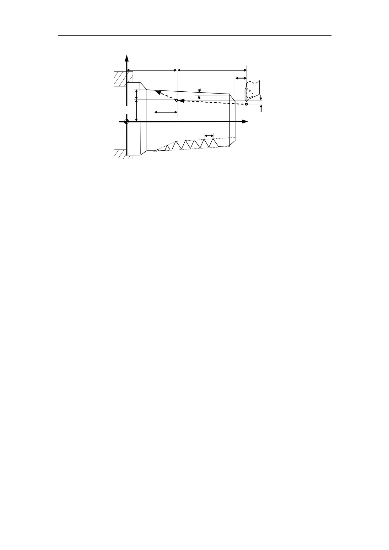
Figure 3.17 Thread Cutting with Constant Lead (G32)
Function
Cylindrical thread, taper thread and face thread can be machined with G32.
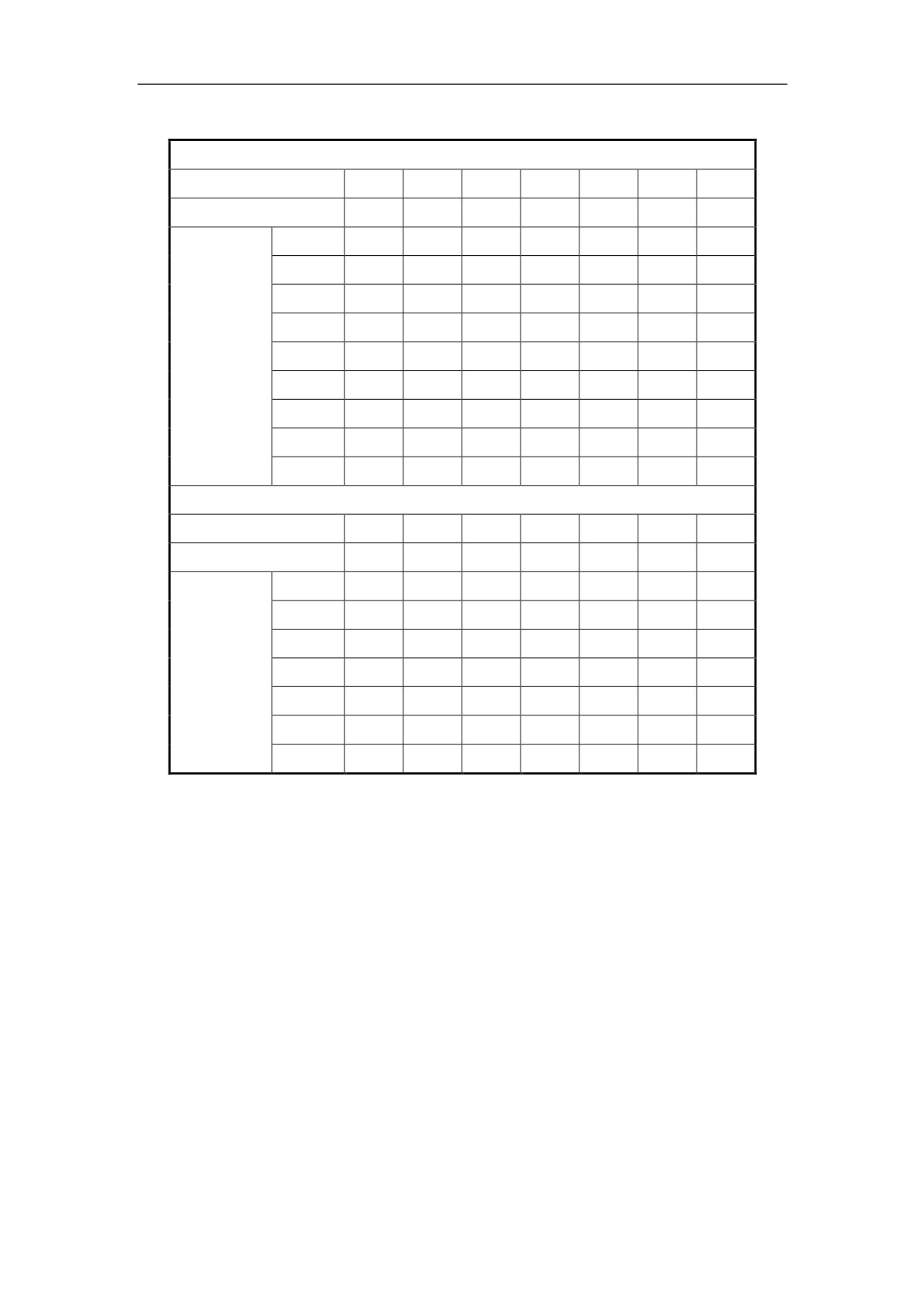
Thread cutting is form turning and the feed is much. If the tool intensity is low, it is
required to feed cutting at serveral times. The following table is the general feed times
and amount of thread cutting.
43
3. Interpolation Function
Table 3-1 feed times and amount of thread cutting
Thread in metric measurement
Lead
1.0
1.5
2
2.5
3
3.5
4
Threads (radius)
0.649
0.974
1.299
1.624
1.949
2.273
2.598
Once
0.7
0.8
0.9
1.0
1.2
1.5
1.5
Twice
0.4
0.6
0.6
0.7
0.7
0.7
0.8
Three
0.2
0.4
0.6
0.6
0.6
0.6
0.6
feed times
Four
0.16
0.4
0.4
0.4
0.6
0.6
and
Five
0.1
0.4
0.4
0.4
0.4
amount
Six
0.15
0.4
0.4
0.4
(diameter)
Seven
0.2
0.2
0.4
Eight
0.15
0.3
Nine
0.2
Thread in inch measurement
Threads/in
24
18
16
14
12
10
8
Threads (radius)
0.678
0.904
1.016
1.162
1.355
1.626
2.033
Once
0.8
0.8
0.8
0.8
0.9
1.0
1.2
Twice
0.4
0.6
0.6
0.6
0.6
0.7
0.7
feed times
Three
0.16
0.3
0.5
0.5
0.6
0.6
0.6
and
Four
0.11
0.14
0.3
0.4
0.4
0.5
amount
Five
0.13
0.21
0.4
0.5
(diameter)
Six
0.16
0.4
Seven
0.17
Note:
1) The spindle speed should remain constant during rough cutting and finish
cutting.
2) The feed hold function is ineffective during the thread cutting. Even though
the “feed hold” button is pressed, it is effective until the thread cutting is done.
3) It is not recommended to use the constant surface speed control during the
thread cutting.
4) Allowant amount must be specified to avoid the error.
44
3. Interpolation Function
Example
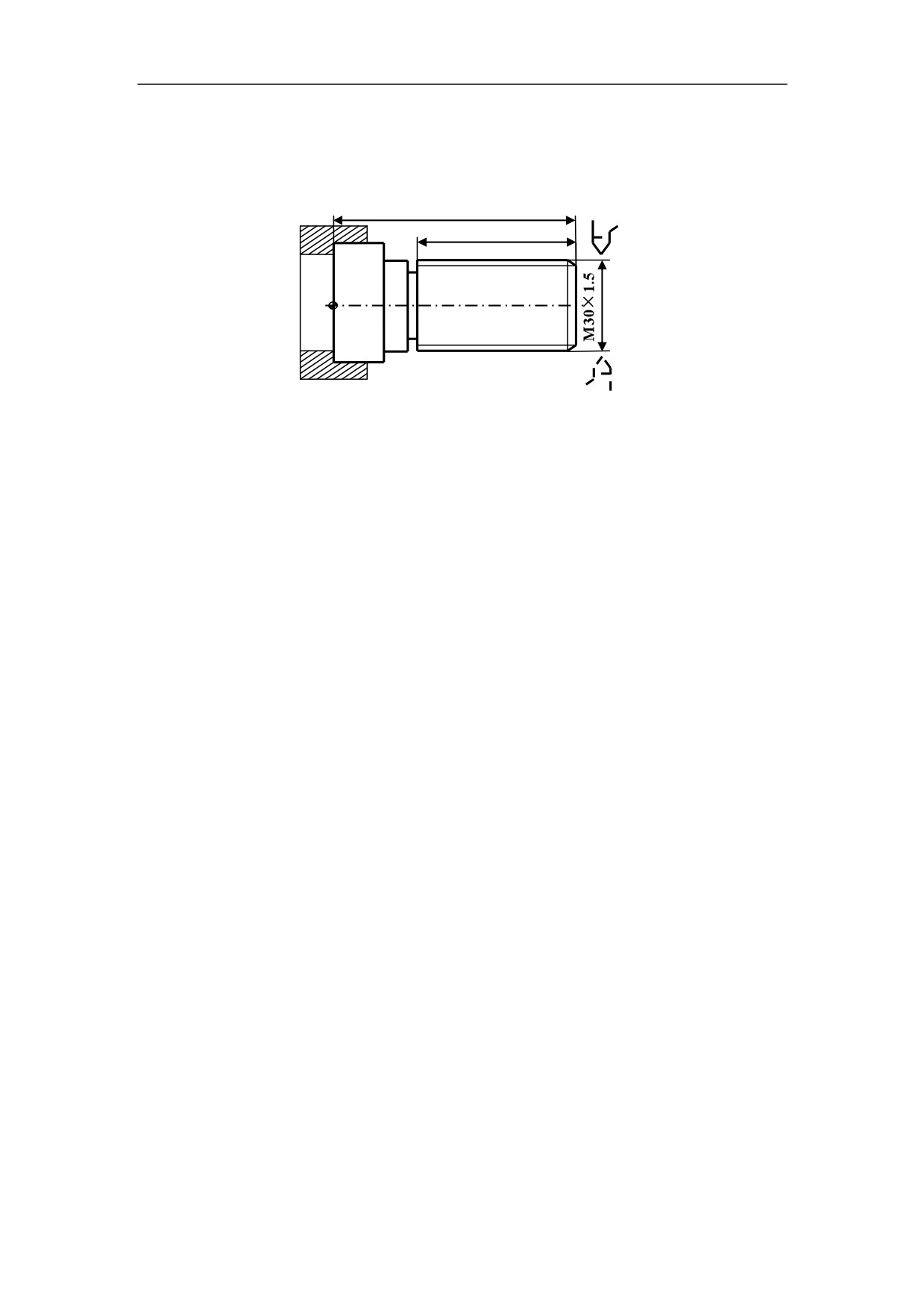
Given that F=1.5mm, =1.5mm, =1mm, cutting for four times and each cutting
depth is separately: 0.8mm, 0.6 mm, 0.4mm, 0.16mm. It is diameter programming.
100
80
Figure 3.18 Thread Cutting - Example
%3316
N1 T0101
N2 G00 X50 Z120
N3 M03 S300
N4 G00 X29.2 Z101.5
N5 G32 Z19 F1.5
N6 G00 X40
N7 Z101.5
N8 X28.6
N9 G32 Z19 F1.5
N10 G00 X40
N11 Z101.5
N12 X28.2
N13 G32 Z19 F1.5
N14 G00 X40
N15 Z101.5
N16 U-11.96
N17 G32 W-82.5 F1.5
N18 G00 X40
N19 X50 Z120
N20 M05
N21 M30
45
3. Interpolation Function
3.6 Tapping (G34)
Programming
G34 K_ F_ P_
Explanation of the parameters
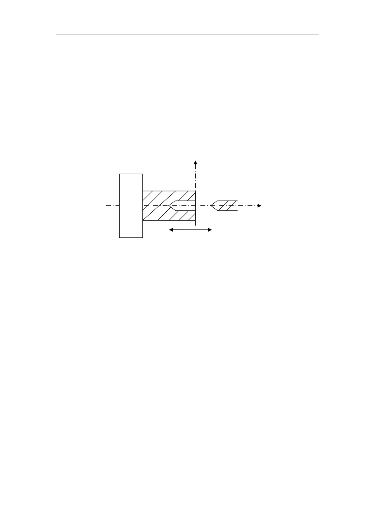
K The distance from the starting point to the bottom of the hole
F Thread lead
P Dwell time at the bottom of a hole
X
Z
K
Figure 3.19 Rigid Tapping
Function
With this command, the operator can rigid tap a thread.
In general, there is overshoot of the tap at the bottom of the thread during the
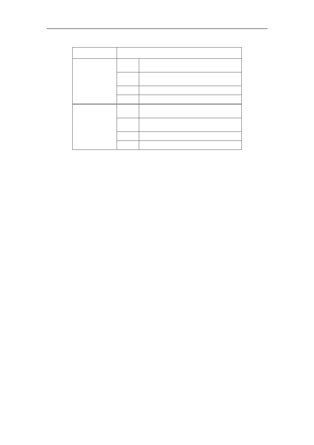
spindle-braking portion of the tapping cycle. It can be set by PMC parameters (Table
3-1) to eliminate the overshoot errors.
46
3. Interpolation Function
Table 3-2 PMC parameters
CNC system
PMC parameters
Maximum spindle speed during
#0062
tapping
Minimum spindle speed during
#0063
HNC 18/19i
tapping
#0064
Dwelled unit for tapping
#0065
Optional dwelled unit for tapping
Maximum spindle speed during
#0017
tapping
Minimum spindle speed during
#0018
HNC 21/22
tapping
#0019
Dwelled unit for tapping
#0030
Optional dwelled unit for tapping
Optional dwelled unit for tapping is only effective when “dwelled unit for tapping” is
assigned to “0”. Moreover, it is not necessary to restart the system.
The following formular is to calculate the dwelled unit (X):
D =
(S * S / C) * X / 10000 = L * 360 / F
D dwelled amount
S spindle speed
C Transmission gear ratio
X dwelled unit
L overshoot error
F thread lead
Since the workpiece is chucked on the spindle, the spindle decceleration time of
turning machine is more than a milling machine’s. The quicker the spindle rotates, the
quicker the feedrate on Z axis is, and then the more time the decceleration time takes.
Thus, the spindle speed should be set accoording to the thread length.
47
3. Interpolation
Function
Example
The following is a tested data for tapping when the thread lead is 1.25mm.
%0034
T0101
S100
G90G1X0Z0F500
G34K-10F1.25P2
S200
G90G1X0Z0F500
G34K-10F1.25P2
S300
G90G1X0Z0F500
G34K-10F1.25P2
S400
G90G1X0Z0F500
G34K-20F1.25P2
S500
G90G1X0Z0F500
G34K-30F1.25P3
S600
G90G1X0Z0F500
G34K-40F1.25P3
S700
G90G1X0Z0F500
G34K-50F1.25P3
S800
G90G1X0Z0F500
G34K-50F1.25P2
S1000
G90G1X0Z0F500
G34K-60F1.25P3
M30
48
3. Interpolation Function
3.7 Direct Drawing Dimension Programming (G01)
Angles of straight lines, chamfering value, corner rounding values, and other
dimensional values on machining drawings can be programmed by directly inputting
these values. In addition, the chamfering and corner rounding can be inserted
between straight lines having an optional angle. It is called direct drawing dimension
programming.
This programming is only valid in turning system G01.
3.7.1 Instruct a line
Programming
G01 X_Z_A_
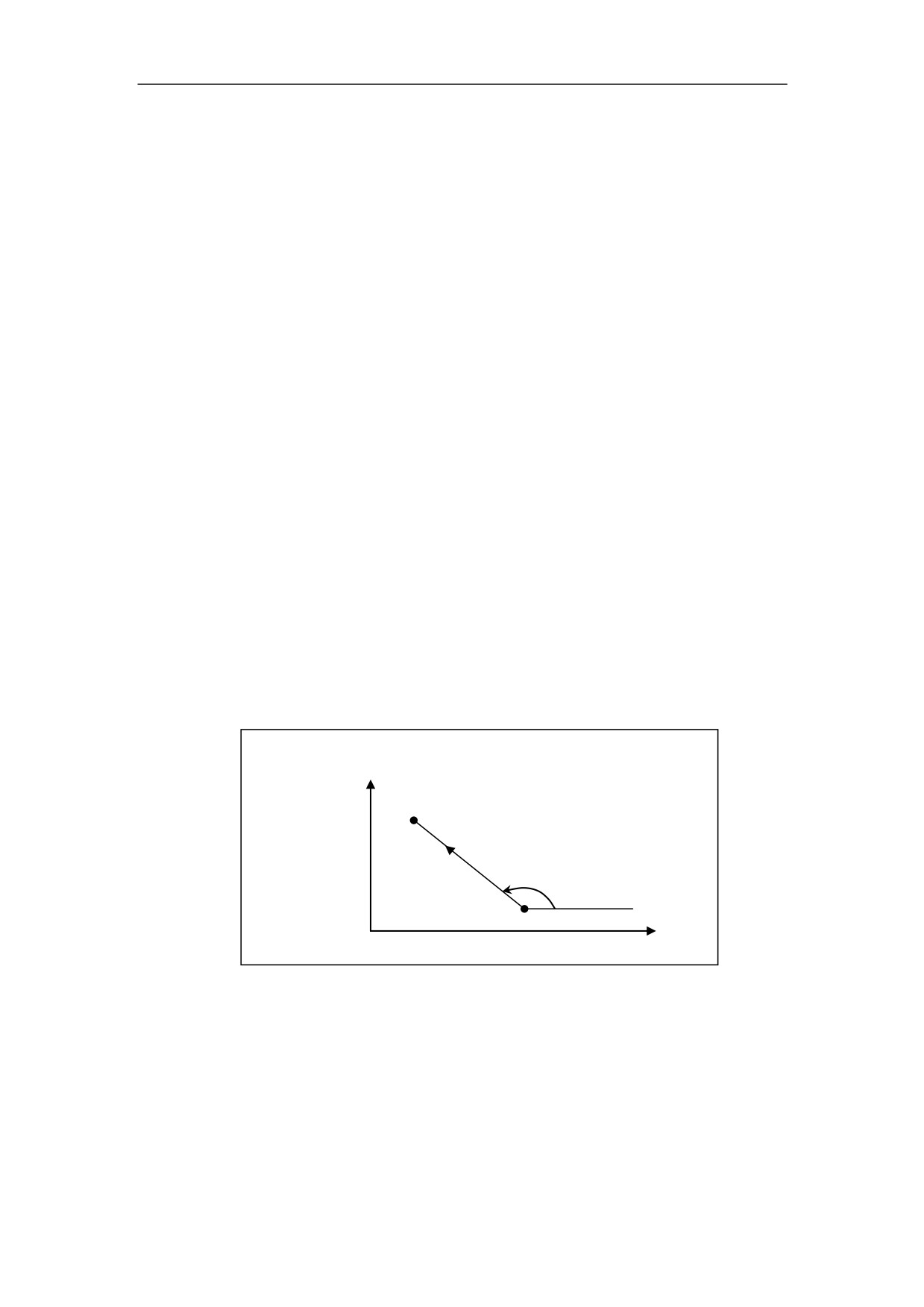
Explanation of the parameters
X_Z_: Line location address;
A_: Angle between linear motion direction and the positive Z-axis direction. Counter
clockwise is positive, while clockwise is negative. Unit: degree.
X
(X2, Z2)
X1_Z1_
X2_( Z2_)A_;
A
(X1, Z1)
Z
Note: the target position only needs to specify a movement value in one direction.
E.g.:Z50a45 or X100a45
49
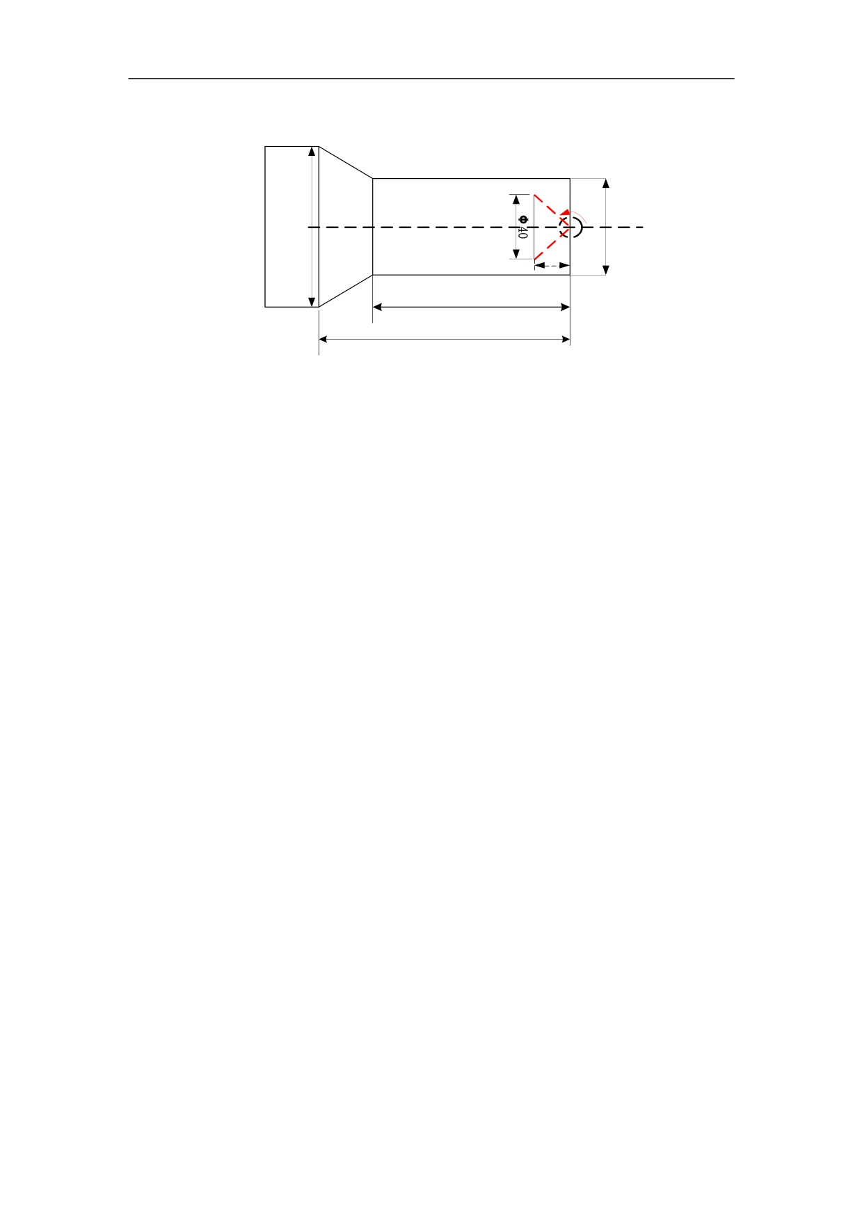
3. Interpolation Function
Example
135゜
Φ 80
Φ 50
Φ 40
70
80
%3324
N1 T0101
N2 M03S400
N3 G00 X100Z40
N4 G00 X0Z0
N5 G01X40A135
N6 G00 X100Z40
N7 M30
3.7.2 Rounding
Programming
G01 X_Z_R_
G01 X_Z_
Explanation of the parameters
X_/Z_: Line location address;
R_: Rounding radius;
Function
An arc is inserted between two linear interpolations. This arc is tangent to the two
lines.
50
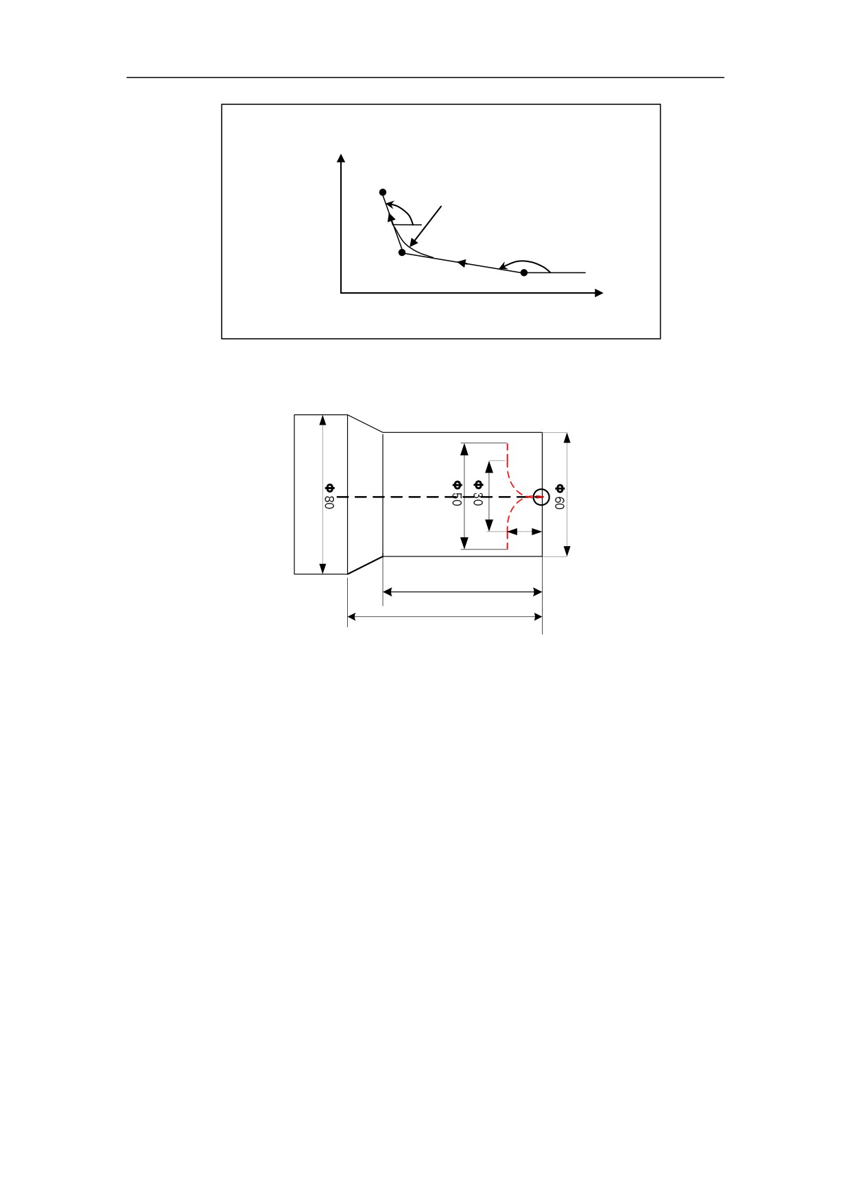
3. Interpolation Function
X
(X3, Z3)
X2_Z2_R1_;
A2 R1
X3_Z3_
A1
(X2, Z2)
(X1, Z1)
Z
Example
Φ 15
70
80
%3325
N1 T0101
N2 M03 S400
N3 G00 X100 Z40
N4 X0 Z0
N5 G01 X0 Z-15 R15
N6 G01X50 Z-15
N7 G00X100 Z40
N8 M30
3.7.3 Chamfering
Programming
G01 X_Z_C_
G01 X_Z_
51
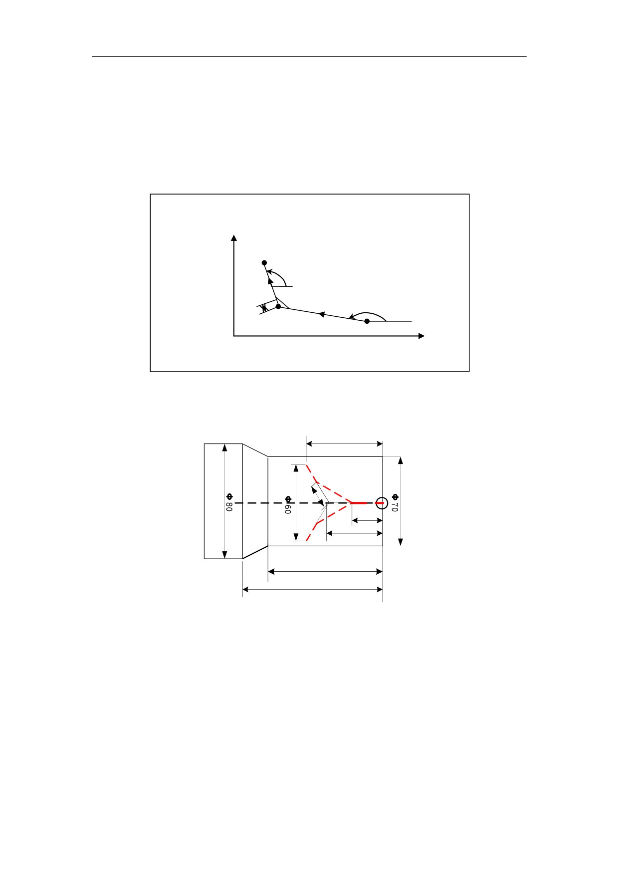
3. Interpolation Function
Explanation of the parameters
X_Z_: Line location address;
C_: Chamfer edge length;
Function
Chamfering is inserted between two linear interpolations.
X
X2_Z2_C1_;
(X3, Z3)
X3_Z3
A2
A1
C1
(X2, Z2)
(X1, Z1)
Z
Example
Φ 50
C10
Φ 10
Φ 20
70
80
%3326
N1 T0101
N2 M03 S400
N3 G00 X100 Z40
N4 X0 Z0
N5 G01 X0 Z-20 C10
N6 G01X60Z-50
N7 G00X100 Z40
N8 M30
52
3. Interpolation Function
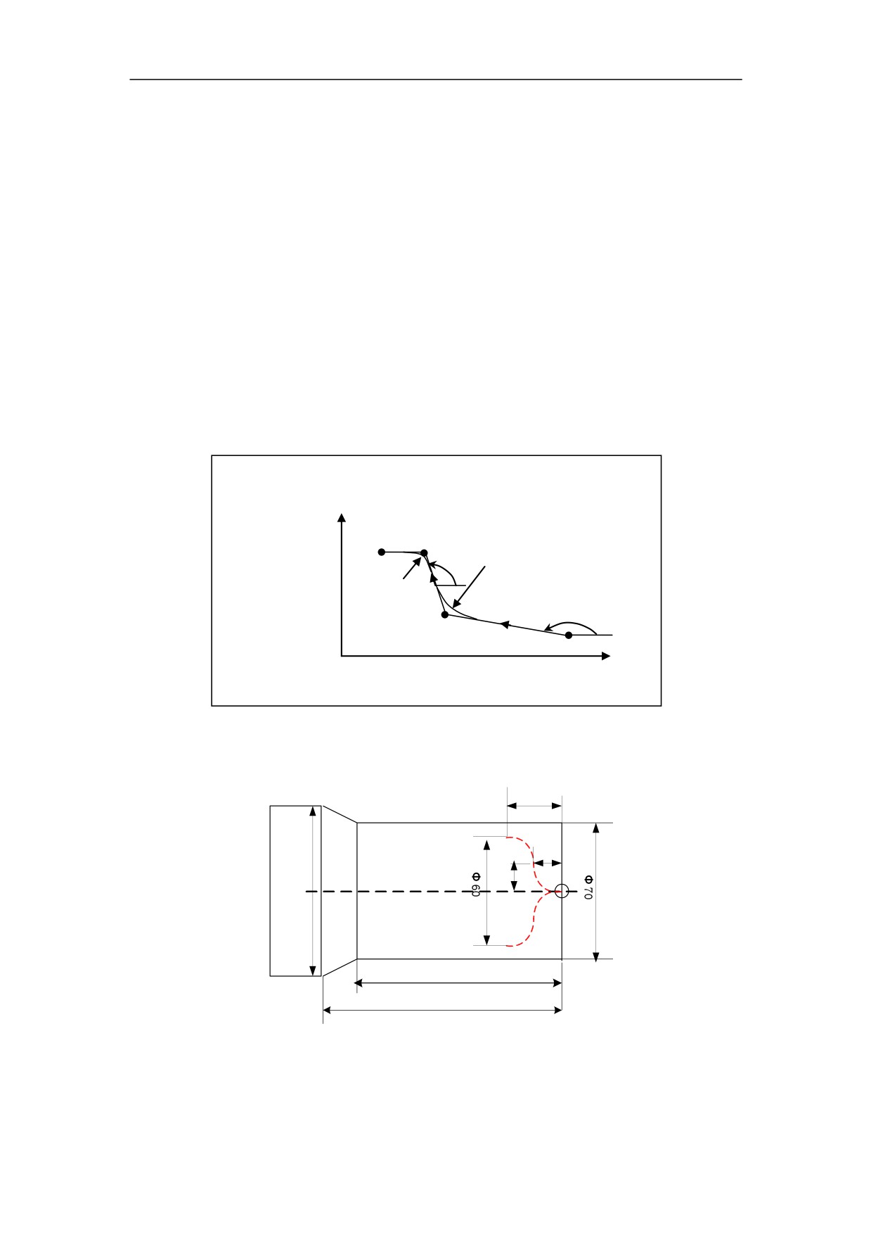
3.7.4 Continuous Rounding
Programming
G01 X_Z_R_
G01 X_Z_R_
G01 X_Z_
Explanation of the parameters
X_/Z_: Line location address;
R_: Rounding radius;
Function
Circular Interpolation is continuously inserted between two linear interpolations.
X
X2_Z2_R1_;
X3_Z3_R2_;
(X4, Z4)
(X3, Z3)
X4_Z4_
A2 R1
R2
A1
(X2, Z2)
Z
Example
Φ 30
Φ 15
Φ 15
Φ 80
Φ 70
Φ 80
%3327
N1 T0101
53
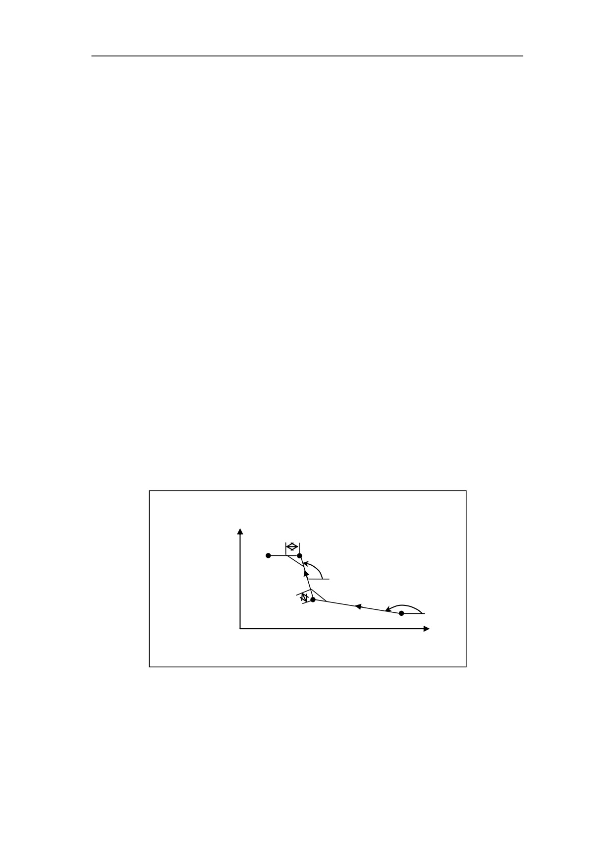
3. Interpolation
Function
N2 M03 S400
N3 G00 X100 Z40
N4 X0 Z0
N5 G01 X0 Z-15 R15
;the first rounding
N6 G01 X60 Z-15 R15
;the second rounding
N7 G01 X60 Z-30
N8 G00X100 Z40
N9 M30
3.7.5 Continuous Chamfering
Programming
G01 X_Z_C_
G01 X_Z_C_
G01 X_Z_
Explanation of the parameters
X_/Z_: Line location address;
C_: Chamfer edge length;
Function
Chamfering is continuous inserted between two linear interpolation.
X
X2_Z2_C1_;
C2
X3_Z3_C2_;
(X3, Z3)
X4_Z4_
A2
(X4, Z4)
C1
A1
(X2, Z2)
Z
54
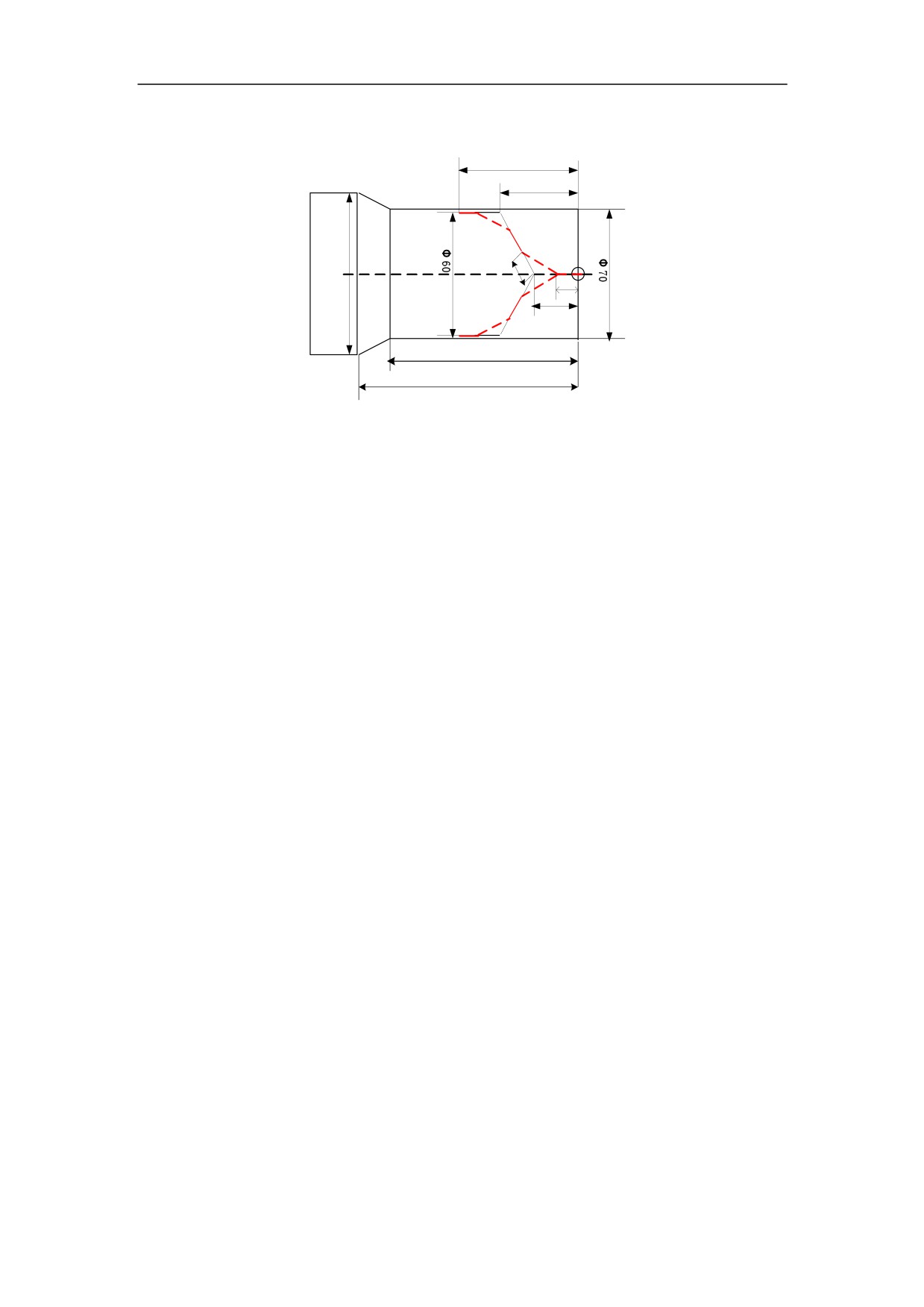
3. Interpolation Function
Example
Φ 70
Φ 50
Φ 80
C10
Φ 10
Φ 20
Φ 70
Φ 80
%3328
N1 T0101
N2 M03 S400
N3 G00 X100 Z40
N4 X0 Z0
N5 G01 X0 Z-20C10
;the first chamfering
N6 G01 X60 Z-50C10
;the second chamfering
N7 G01 X60 Z-70
N8 G00X100 Z40
N9 M30
3.7.6 Rounding then Chamfering
Programming
G01 X_Z_R_
G01 X_Z_C_
G01 X_Z_
Explanation of the parameters
X_/Z_: Line location address;
R_: Rounding radius;
C_: Chamfer edge length;
Function
Round and Chamfering are inserted between two linear interpolation.
55