Series HSV-180AS AC Spindle Drive. User Manual (V1.00 2012.4) - page 5

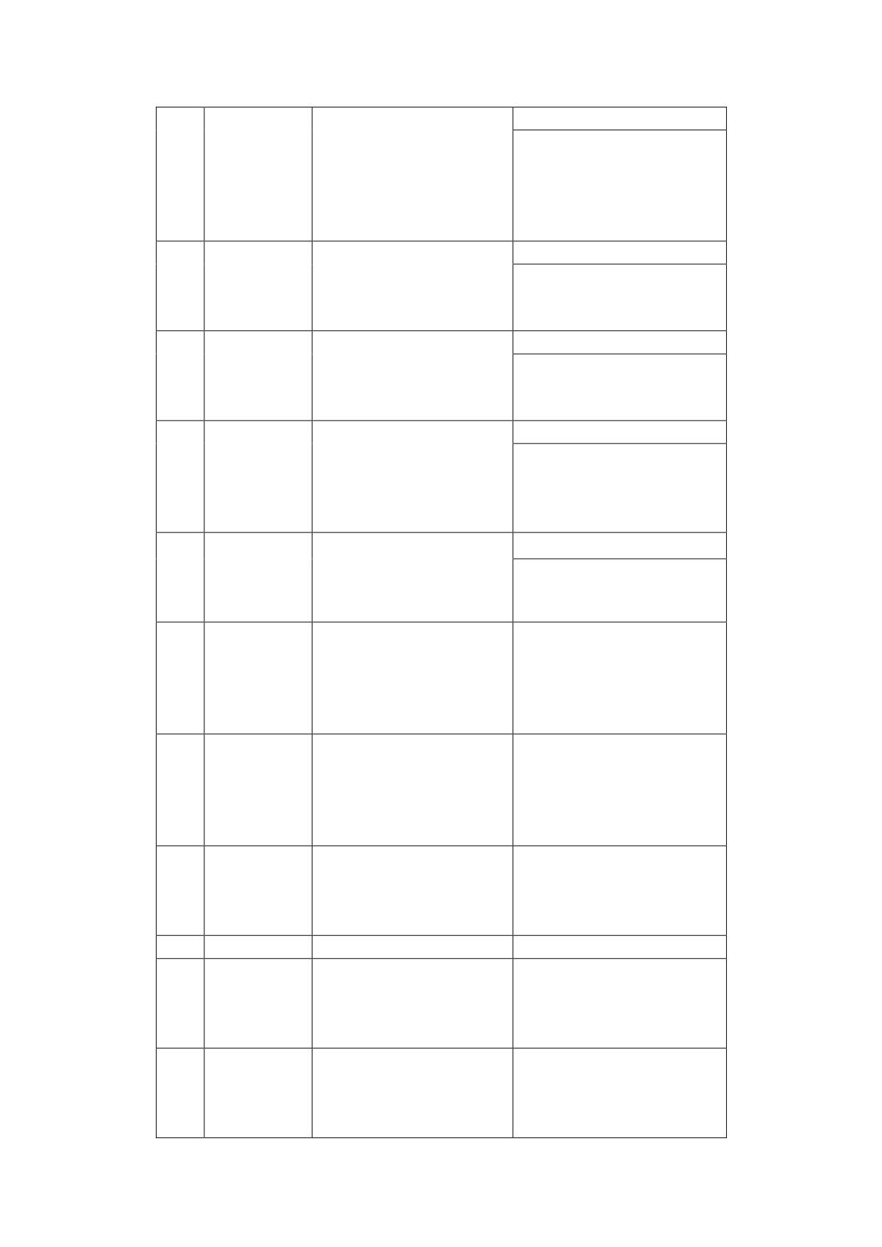
frequency of the command pulse. Note:
the value is too large may cause
oscillation or overshooting.
3. The parameter value is determined
according to the type of spindle drive
and operating load.
1. Set the parameters to the test range
for C- axis position tolerance.
1 to
Test range
2. Under the C-axis control mode, when
12
32767p
for position
the value for the position tolerance
ulse
tolerance
is over the parameter value, the
tolerance alarm is generated.
1. Set parameters to the position feed
0 to
forward gain.
100
Position
2. When the parameter is set to 100%,
feed forward
the position lag value is 0 at any
gain
frequency of the command pulse.
3. The high-speed response is improved
16
as the feed forward gain of the
position loop increased. This can
cause instability and oscillation.
4. If the fast response is not
required, the parameter can be set to
0.
Command
1. Set parameters to the command pulse
pulse input
mode
22
0 to 3
mode
2. Set parameters to one of the 3 types
of input mode.

z
0: indicates two-phase positive
pulse input
z
1: indicates pulse + direction
z
2: indicates CCW pulse/CW pulse
3. CCW is defined as forward for the
spindle rotating counterclockwise
(looking from the axial direction).
4. CW is defined as reverse for the
spindle rotating clockwise (looking
from the axial direction).
1.
This parameter is used to select
control mode for the spindle
drive.
z
0: indicates the C-axis position
control mode, receiving the
position pulse input command.
z
1: indicates the external speed
Selection of
control mode, receiving speed
23
0 to 3
control mode
analog input command.
z
2: indicates the external speed
control mode, receiving speed
pulse input command.
z
3: indicates the internal speed
control mode. The internal speed
command is set by movement
parameter PA-20.
Speed
1. Set parameters to the proportional
25 to
42
proportional
gain for speed regulator under the
32767

gain
position control mode.
2. Gain and rigidity will be enhanced
as the parameter value increases. This
parameter is determined by the actual
spindle drive system type and the
load. Generally, load inertia grows as
the value increases.
3. It is recommended that the value be
larger if no oscillation exists.
1. Set this parameter to the speed
regulator integration time constant.
2. Integration speeds up as the value
decreases. This parameter is
Speed
5 to
determined by the actual spindle drive
43
integral
32767
system type and the load. Generally,
time
load inertia grows as the value
constant 2
increases.
3. It is recommended that the value be
smaller if no oscillation exists.
1. Set parameters to the flux current
Flux current
value under position control mode. The
for position
10 to
46
parameter is specified by PA-33 and
control mode
100%
PA-46, and the flux current value is
PA-33×PA-46.
Parameters setting in the position control mode (PA-23 is set to 0):
1. The position loop feature is adjusted by setting PA-0.
2. The speed loop feature is adjusted by setting PA-42 and PA-43.
3. The current loop feature is adjusted by setting PA-27 and PA-28.
4. The value of flux current is calculated by multiply PA—53by PA-33
by PA-46. There is an example, if the value of PA—53 is 100,PA-33
is 50and PA-46 is 110, flux current value = 100 ×50%×110 =55
Note:
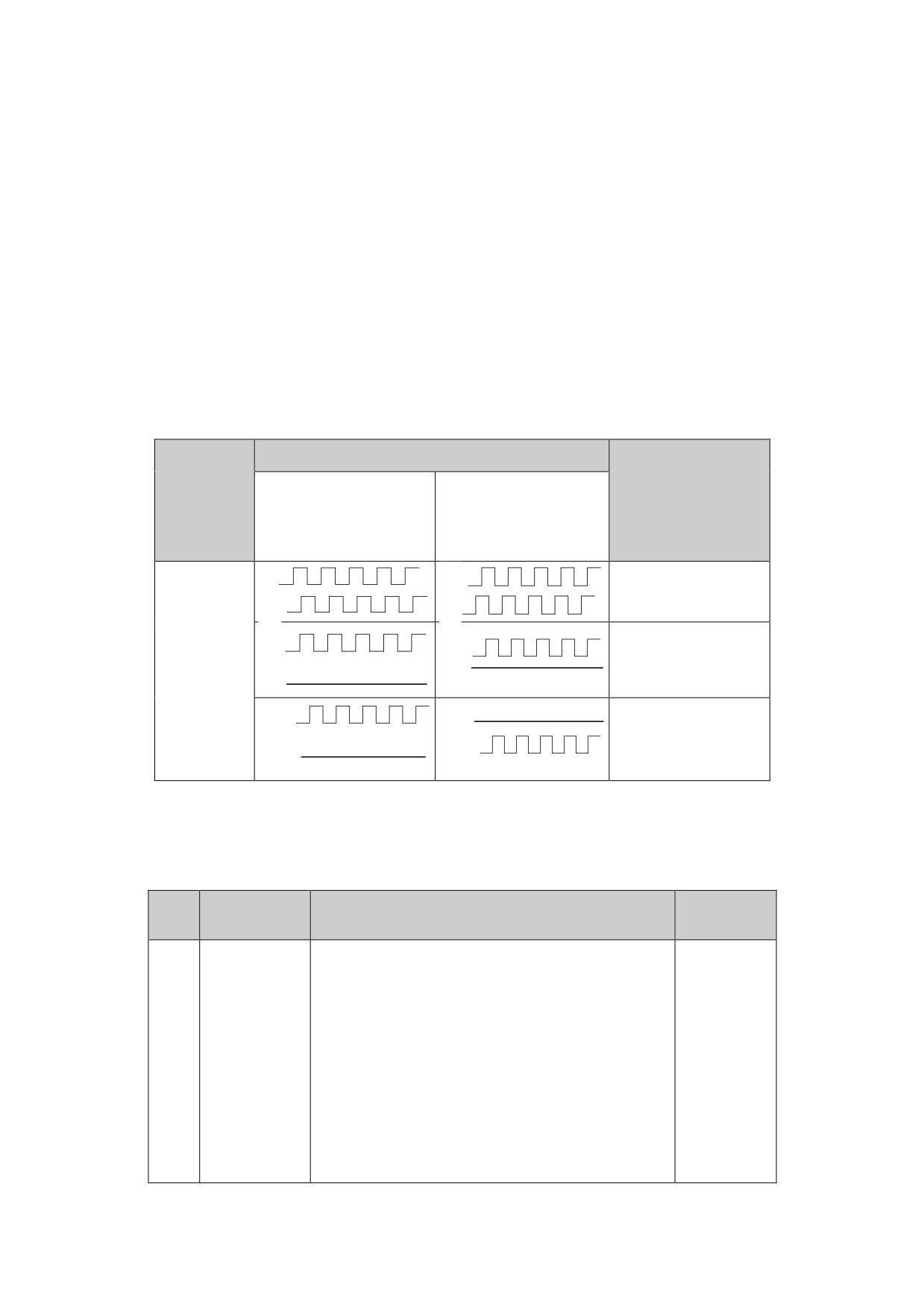
In the position control mode, the spindle drive can receive three
types of pulse command. You can select one of the three commands by
setting the movement parameter PA-22 (indicating the command pulse
input mode).
Table 7.11 Command pulse
pulse
Command Pulse
Input Mode
Signal
(movement
input pin
Forward
Reverse
parameter
PA-22) Setting
A
A
0 (positive
B
B
pulse)
CP
XS4-14
CP
CP
XS4-15
1 (pulse +
DIR
DIR
DIR
direction)
XS4-16
CW
CW
XS4-17
CCW
CCW
2(CW+CCW)
(CW+CCW)
7.2.4 Parameters Related to Speed Control Mode
Table 7.12 Parameters related to speed control mode
Value
NO.
Parameter
Function
Range
1.Set parameters to the proportional
gain for the speed regulator.
2.Gain and rigidity will be enhanced as
the parameter value increases. This
Speed
parameter is determined by the actual
2
proportion
25 to 5000
spindle drive system type and the load.
al gain 1
Generally, load inertia grows as the
value increases.
3.It is recommended that the value be
larger if no oscillation exists.
1.Set this parameter to the speed
regulator integration time constant.
2.Integration speeds up as the value
Speed
decreases. This parameter is determined
integral
5 to
3
by the actual spindle drive system type
time
32767mS
and the load. Generally, load inertia
constant 1
grows as the value increases.
3.It is recommended that the value be
smaller if no oscillation exists.
1.Set this parameter to the features of
low-pass filter for speed feedback.
2.Noise produced by motors and cut-off
frequency decreases as the value
Speed
increases. If the load inertia is large,
feedback
decrease the value to prevent from slow
4
0 to 9
filter
response or oscillation.
factor
3.The cut-off frequency increases and
speed feedback response becomes faster
as the value decreases. If high speed
feedback response required, decrease
the value.
1. The value indicates the time required
Decelerati
for motor slow down from the maximum
5
on time
0 to 1800
speed to 0r/min.
constant
2. Deceleration features linearity.
1. The value indicates time required for
Accelerati
motor speed up from 0 r/min to the
6
on time
0 to 1800
maximum speed.
constant
2. Acceleration features linearity.
1.Set this parameter to the
relationship between voltage and rotary
speed under analogue speed command
Analogue
mode.
speed
7
0 to 12000
command
2.The value is the speed corresponding
input gain
to the + 10 V voltage ( unit: 1 r/min)
3.The valve is effective under the
external speed control mode.
Speed
1. In the speed control mode, this
command
parameter is used to adjust zero drift
-1023 to
8
zero drift
input by external analogue speed
1023
compensati
command. The method of adjustment is as
on
follows:

z Perform short-connection
between the analogue control
input terminal and grounding
wire for signal.
z Set this parameter to the value that
stops the operation of the motor.
Speed
1. In the speed control mode, this
command
parameter is used to adjust the
80% to
9
gain
amplification factor of PA--7.
120%
adjusting
2. The value is effective under the
factor
external speed control mode.
1. Set parameters to speed reached.
2. In the non-position control mode, if
the motor speed tracking error is less
0 to 32767
than the value, the switch signal for
speed
r/min
speed reached is connected, otherwise
11
reached
it is disconnected.
range
3. In the position control mode, this
parameter is ineffective.
4. The parameter value has no relation
to the rotary direction.
1. Set parameter to the maximum speed
Maximum
0 to
limit.
17
speed
16000(uni
2. The parameter value has no relation
limit
t:1r/min)
to the rotary direction.
-20000 to
1. Set parameters to the internal speed.
20000
20
Internal
2. In the internal control mode, select
(unit:
speed
the internal speed as the speed command.
1r/min)
JOG
1. Set this parameter to the speed in the
0 to
21
operating
JOG mode.
500(unit:
speed
1r/min)
1. Set parameters to the command pulse
input mode.
2. Select one of the 3 types of input
mode by setting the parameter.
Command
z
0: indicates two-phase positive
22
pulse
pulse input
0 to 3
input mode
z
1: indicates pulse + direction
z
2: indicates CCW pulse/CW pulse
3. CCW is defined as forward for the
spindle rotating counterclockwise as
looking from the axial direction.

4. CW is defined as reverse for the
spindle rotating clockwise as looking
from the axial direction.
1. This parameter is used to select the
control mode for spindle drive.
z
0: indicates the C-axis position
control mode, receiving the
position pulse input command.
z
1: indicates the external speed
Selection
control mode, receiving speed
23
of control
analog input command.
0 to 7
mode
z
2: indicates the external speed
control mode, receiving speed pulse
input command.
z
3: indicates the internal speed
control mode. The internal speed
command is set by movement parameter
PA-20.
1.Set parameters to the zero-speed
reached range.
2. In the non-position control mode, if
the motor speed is less than the value
Zero-speed
of this parameter, the switch signal for
0 to
29
reached
zero-speed output is connected.
300(unit:
range
Otherwise, it is disconnected.
1r/min)
3. In the position control mode, this
parameter is ineffective.
4.The parameter value has no relation to
the rotary direction.
Parameter setting in the speed control mode (PA-23 is set to 1, 2
or 3):
1. Speed loop feature is adjusted by setting PA-2 and PA-3.
2. Current feature is adjusted by setting PA-27 and PA-28.
3. Flux current value is determined by setting PA-33.
4. When PA-23 is set to 1, it can receive the internal analog command
with the voltage amplitude no more than 10V (-10V ~+10V or 0~+10V).
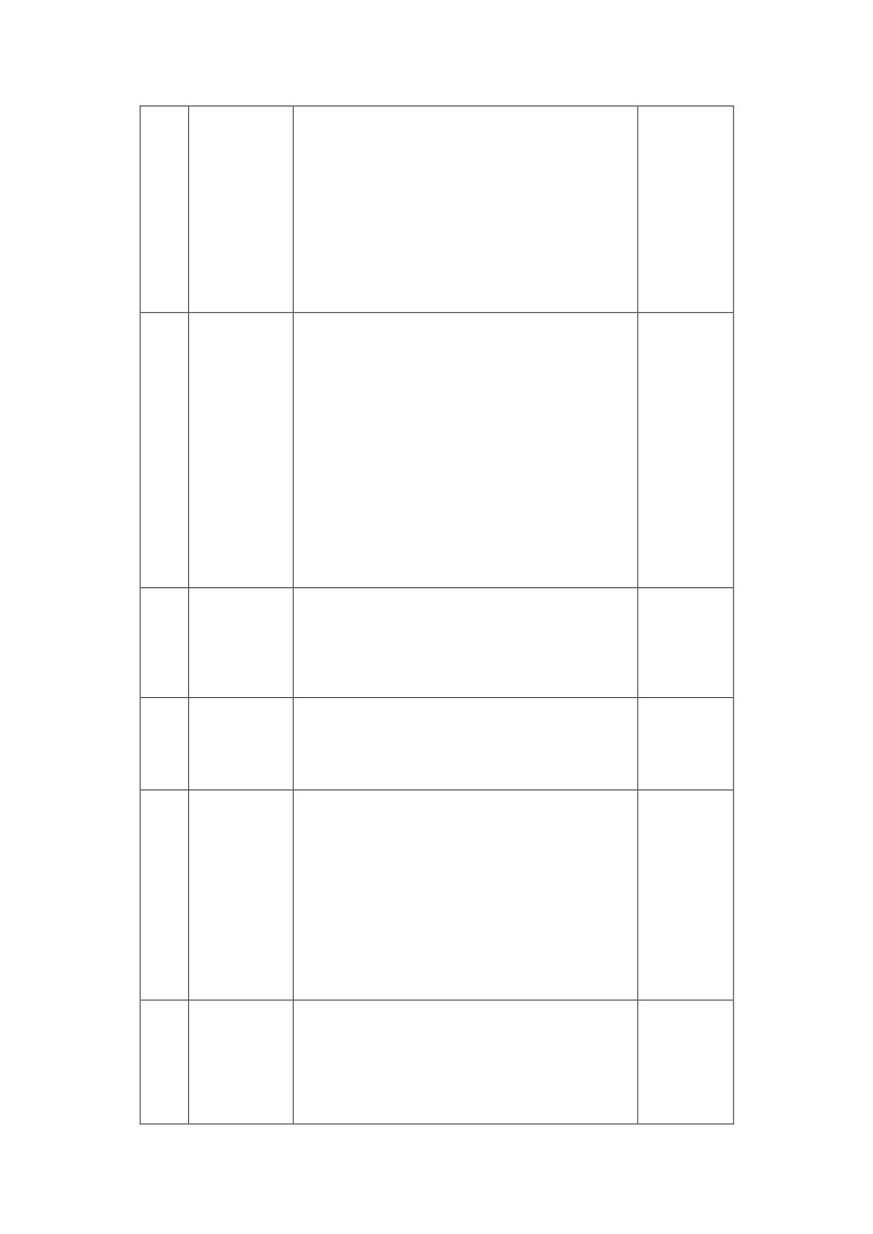
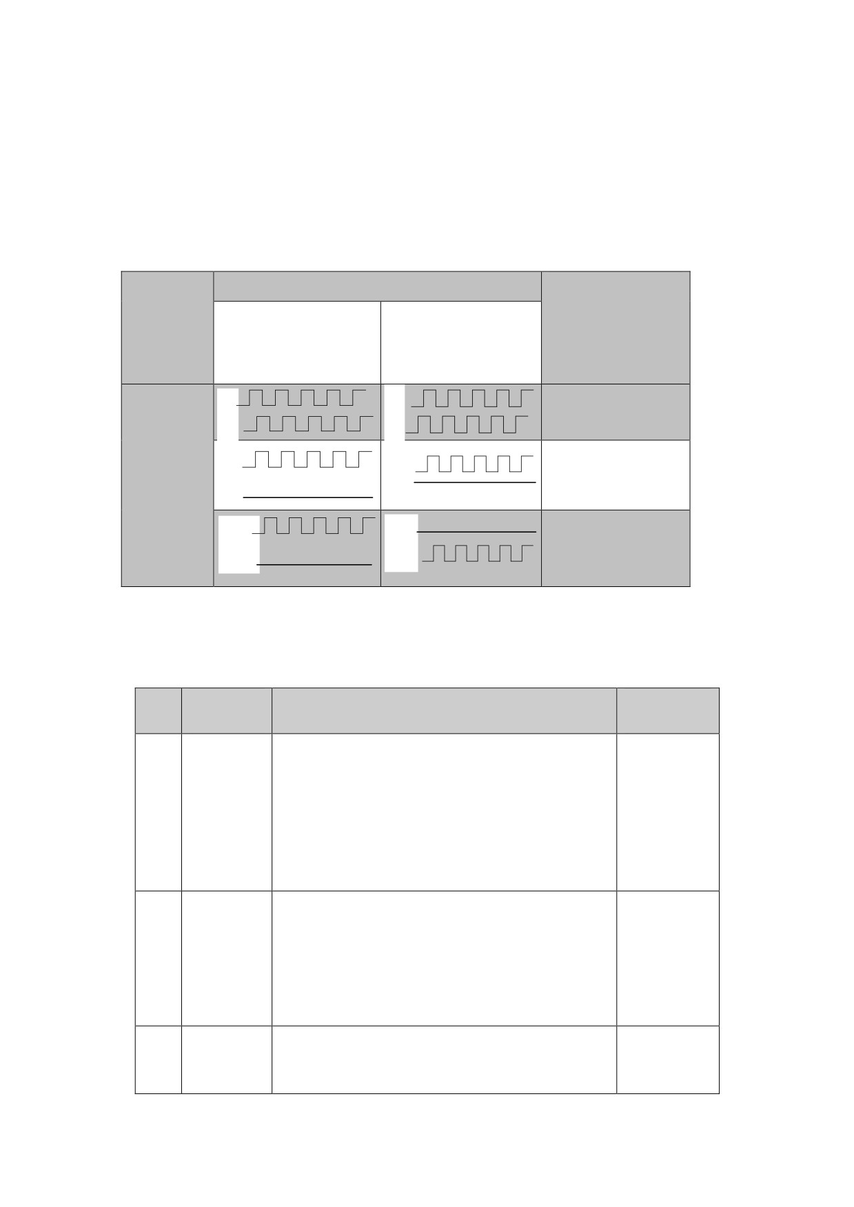
5. When PA-23 is set to 2, it can receive three types of external pulse
commands (positive pulse, pulse + direction, positive and
negative pulse). For the command pulse mode, see Table 7-11.
6. When PA-23 is set to 3, in the internal control mode, the spindle
drive running at the speed specified by PA-20 (without the
external command).
Table 7.12 Command pulse
pulse
Command Pulse
Input Mode
Signal
(movement
input pin
Forward
Reverse
parameter
PA-22) Setting
A
A
0 (positive
B
B
pulse)
CP
XS4-14
CP
CP
1 (pulse +
XS4-15
DIR
DIR
direction)
DIR
XS4-16
CW
CW
XS4-17
CCW
CCW
2
(CW+CCW)
7.2.5 Parameters Related to Output Torque Regulation
Table 7-13 Regulating parameters
Paramete
Value
NO.
Function
r
range
1. Set parameters to the filter time
0 to 499
Torque
constant for the torque command.
Indicates
filter
2. The responding speed becomes slower as
the range
1
time
the value increases, which may cause
is
constant
instability and oscillation.
0~49.9ms
3. The parameter is generally set to 4 if
a slow response is not needed.
Current
1. Set parameters to the current
amplitud
amplitude limit for maximum torque.
e limit
10 to 300
10
Usually the value is between 0.1 to 3
for
times of the rated current of the motor
maximum
2.The value is effective at any time.
torque
Overload
1. Set parameters to the overload current
10 to 200
18
current
of spindle motor. Usually the value is
setting
between 0.1 to 2 times of the rated
current of the motor
2.The value is effective at any time.
1. Set this parameter to the allowable
overloading time of the system.
2. The value indicates the overloading
Overload
19
time per time unit (unit: 0.1s). For
10 to 30000
time
example, if the value is 200, the
allowable overloading time is 20s.
3. The value is effective at any time.
1. Set this parameter to the proportional
gain of current loop.
Current
2. Decrease the value to decrease the
control
27
loud noise of current during motor
25 to 32767
proporti
operation.
onal gain
3. However, a small value will decrease
the feedback response.
1. Set this parameter to the integration
time of current loop.
Current
2. Increase the value to decrease the
control
28
loud noise of current during motor
1 to 32767
integrat
operation.
ion time
3. A big value will decrease the feedback
response.
7.2.6 Parameters Related to the Oriented Control
Table 7-16 Oriented Parameters
NO.
Parameter
Function
Value Range
1.Set parameters Speed proportional
gain of spindle to motor
Speed
2. The larger of the setting value,
2
proportion
the higher of the gain value and
25to 5000
al gain 1
stiffness. Parameter values depend on
the spindle drive unit model and load
value.
1.Set parameters speed integral time
Speed
of spindle to motor
integral
2. The smaller of the setting value,
3
5to 32767
time
the faster of the integral value. The
constant 1
parameter values depend on the type
and load of the spindle drive system
Speed
1. Set parameters to the speed ratio
13
1 to 32767
ratio
of spindle to motor.

numerator
2. PA-13 is the numerator and PA--14
of spindle
is the denominator of the speed ratio.
to motor
During operation, if the spindle
Speed
makes three turns per time and the
ratio
spindle motor makes five, the value of
denominato
PA-13 is 5 and PA-14 is 3.
14
1 to 32767
r of
spindle to
motor
1. Set parameters to the minimum
position error range in the spindle
Spindle
orientation finished.
orientatio
0 to 100
37
2. When the position error is smaller
n finished
Pulse
than the value, the
range
orientation-finished output switch
(ORN_FIN) is connected.
Spindle
1. Set parameters to the spindle
40 to
38
orientatio
orientation speed.
600(1r/min)
n speed
1. Set parameters to the spindle
Spindle
orientation speed. The value is set by
-3276to
39
orientatio
taking the zero pulse position of the
32767
n position
motor encoder or spindle encoder as a
reference.
Incrementa
l angle for
Set parameters to the incremental
40
indexing
angle for indexing orientation
0 to 32767
orientatio
n
1.Set parameters position
Position
proportional gain for orientation
proportion
mode.
al gain for
2. The larger of the setting value,
44
10~2000
orientatio
the higher of the gain value and
n mode
stiffness. Parameter values depend on
the spindle drive unit model and load
value.
Flux
current
1.Set parameters Flux current for
45
for
30~100
orientation mode.
orientatio
n mode
Spindle
1.The spindle encoder resolution is
47
1~32767
encoder
four times of the frequency

resolution
The offset
1.Set parameters offset angle for
angle for
indexing orientation
48
indexing
0~18
orientatio
n
Parameters setting in the orientation mode:
1. The position loop feature is adjusted by setting PA-44.
2. The speed loop feature is adjusted by setting PA-2 and PA-3.
3. The current loop feature is adjusted by setting PA-27 and PA-28.
4. The flux current value is specified by multiplying PA--53*PA-33
by PA-46. For example, if PA--53=100 (10A),PA--33=60 (80﹪),
PA--46=110 (110%), the flux current value is 100*60﹪*110﹪=66
(6.6A)
A. Spindle Orientation
1. Spindle motor optic-electrical encoder orientation
z In the spindle motor optic-electrical encoder orientation mode,
connect the encoder to the input interface XS3 for feedback.
z Set PA-13 (indicates speed ratio numerator of spindle to motor)
to 1 and PA-14 (indicates speed ratio denominator) to 1
z According to the actual requirement, set PA-37
z Set the control parameter STA-13 to 0, and spindle
optic-electrical encoder is used for position feedback, in this
case, the command input/output interface XS4 outputs the position
of the spindle optic-electrical encoder.
z Set the control parameter STA-15 to 0, spindle motor
optic-electrical encoder is used for orientation, and according
to the actual requirement, set STA-14 (indicates the spindle
orientation direction).
z
The spindle motor optic-electrical encoder orientation is
applicable in the condition of the speed ratio of spindle to motor
is 1:1.
B. Spindle encoder orientation
z
In the spindle encoder orientation mode, connect the spindle
optic-electrical encoder to the input interface XS3 for feedback,
and connect spindle encoder to the interface XS2 for feedback.
z
Set the movement parameter PA-25 (indicates the spindle motor
optic-electrical encoder resolution) to 0 (indicates that the
resolution is 1024), and set PA-47 according to the actual used
spindle encoder.
z
According to the actual requirement, set PA-37, PA-38, and PA-39,
in this case, the range for spindle orientation position is from
0 to the value of PA-47.
z
Set the control parameter STA-13 to 1, and the command interface
uses spindle encoder to feedback position. In this case, the
interface XS4 outputs the position of the spindle
optic-electrical encoder.
z
Set STA-15 to 1 (indicates spindle encoder orientation), and set
STA-14 (spindle orientation direction) according to the actual
requirement.
Note:
z To prevent interference, the interface XS2 adopts AM26LS32
differential receiver to receive differential input signal. The
spindle encoder adopts the differential drive output mode with
the AM26LS31,MC3487 or similar RS422 line drive.
z Connect the spindle encoder to a +5V power supply.
z
The spindle motor optic-electrical encoder orientation is not
applicable in the condition of the speed ratio of spindle to motor
is 1:1.
C. Zero switch Orientation
z
In the zero switch orientation mode, connect A, B-phase of spindle
motor optic-electrical encoder to the interface XS3 for feedback,
disconnect the Z-phase of spindle motor optic-electrical encoder,
and connect the Z-phase of zero switch to the XS3.
z
Set PA-13 (indicates speed ratio numerator of spindle to motor)
to 1 and PA-14 (indicates speed ratio denominator) to 1, set PA-25
(indicates the spindle optic-electrical encoder resolution) to
0 (indicates that the resolution is 1024).
z
According to the actual requirement, set PA-37, PA-38, and PA-39,
in this case, the range for spindle orientation position is from
0 to 4096× n (n indicates the speed ratio of spindle to motor).
z
Set the control parameter STA-13 to 0, and the command interface
uses spindle motor optic-electrical encoder to feedback. In this
case, the interface XS4 outputs the position of the spindle
optic-electrical encoder.
z
Set STA-15 to 0 for spindle motor optic-electrical encoder
orientation, and according to the actual requirement, set STA-14
(indicating the spindle orientation direction).
z
Zero switch orientation is applicable in the condition of the speed
ratio of spindle to motor is 1:1.
Note:
z To prevent interference, the drive uses zero differential output
switch.
7.2.7 Non standard motor parameter settings
Select HSV-180AS series spindle drive unit, refer to table7.3.

If the code cannot be found in Table 7.3, or use other manufacturers
IM spindle motor, you must manually set the operating parameters. Details
as follows:
1. Confirm whether the spindle motor specifications match with the
drive unit specifications
2. Confirm whether the spindle drive unit is installed to support the
spindle motor encoder.
3. Setting parameters according to the type of IM spindle motor:
Setting PA—41 to 2003
Setting PA—59 according to the type of spindle motor
HSV-180AS-035:Setting PA—59 to 1
HSV-180AS-050:Setting PA—59 to 102
HSV-180AS-075:Setting PA—59 to 203
HSV-180AS-100:Setting PA—59 to 304
HSV-180AS-150:Setting PA—59 to 405
According to the actual requirement, set PA—17, PA—24, PA—25,
PA—33, PA—34, PA—35and PA—53
4.For non-standard spindle motors (other than the motor in Table 7.3),
PA-33, according to the following method to adjust the parameters:
spindle motor running at a constant speed by no loading ,
Observe
, appropriately transfer PA-33 to ensure that the
display is 20,000 which is a appropriate value.
5. Setting PA—41 to 1230, saving parameters in the secondary menu ,
and restart the drive unit.
6. Confirmation weather phase sequence of the spindle motor is correct.
7. Drive unit access systems up to running after confirmation.
7.3 Control Parameter Mode
Series HSV-180S spindle drive unit provides 16 control parameters,
see Table 7-6,7-7. For the parameter operation, setting, modifying
and saving.
7.3.1 Control Parameter
Table 7-6 Control Parameters(state control number is 1 )
NO.
Parameter
Function
Description
Command source
0:setting Parameters
0
STA-0
selection
according to PA20
1:NCUC
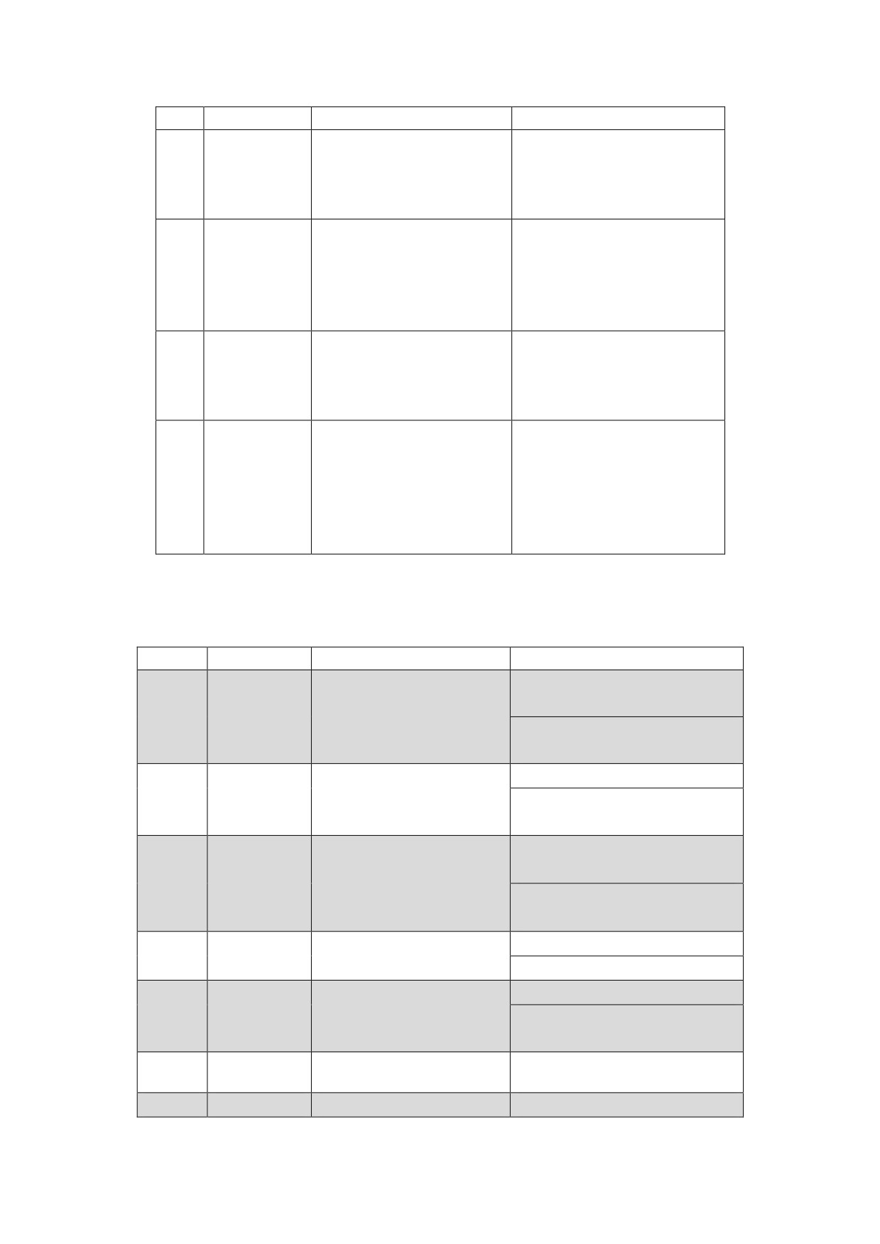
This parameter is used
0: Normal direction
to specify the
direction of position
1: Opposite direction
1
STA-1
command pulse or the
of position command
inversion of speed
pulse or speed command.
command input.
This parameter is used
0: Allow
to specify whether
2
STA-2
feedback break-off
1: Not allow
alarm is allowed.
This parameter is used
0: Allow
to specify whether
3
STA-3
system overspeed
1: Not allow
alarm is allowed.
This parameter is used
0: Allow
to specify whether
4
STA-4
position
1: Not allow
over-tolerance alarm
is allowed.
This parameter is used
0: Allow
to specify whether
5
STA-5
system overload alarm
1: Not allow
is allowed.
This parameter is used
to specify whether the
1: Internal enable
6
STA-6
internal SVR-ON
0: External enable
control start is
allowed.
This parameter is used
to specify whether
1: Not allow
7
STA-7
system main power
0: Allow
undervoltage alarm is
allowed.
This parameter is used
to specify whether
1:Allow
8
STA-8
control mode switch is
0:Not allow
allowed.
9
STA-9
Reserved
This parameter is used
to specify whether
0:Not select
10
STA-10
select the external
1:select
switch orientation
This parameter is used
to specify whether
1:Allow
11
STA-11
spindle encoder A, B
0:Not allow
phase exchange is
allowed.
This parameter is used
to specify whether
1: Not allow
12
STA-12
motor overheat alarm
0: Allow
is allowed.
Command interface
1:Spindle encoder
uses spindle encoder
feedback
13
STA-13
or spindle motor
0: Spindle motor
optic-electrical
optic-electrical
encoder to feedback.
encoder feedback
This parameter is used
1:Reverse orientation
to set the spindle
(CW)
14
STA-14
orientation rotary
0:Forward orientation
direction.
(CCW)
This parameter is used
1:Spindle encoder
to set the spindle
orientation
encoder orientation
15
STA-15
0:Spindle motor
or spindle motor
optic-electrical
optic-electrical
encoder orientation
encoder orientation
7.3.2 Extended control parameters
Figure 7-7 Description of the extended control parameters
(State control word 2)
NO.
Parameter
Function
Description
0:First-order low-pass
This parameter is used
filter.
0
STB-0
to set speed feedback
1:Second-order low-pass
filter
filter
This parameter is used
0:IM spindle motor
1
STB-1
to set type of spindle
1:PM spindle motor
motor
0:Closed-loop control
This parameter is used
method
2
STB-2
to set methods of IM
1:Open-loop correction
Weak magnetic
method
IMSlip compensation
0:No compensation
3
STB-3
selection
1:compensation
Whether the drive unit
0:Allowed
4
STB-4
Overheating alarm is
1:Not allowed
allowed
5
STB-5
6
STB-6
PWM frequency
0:10K
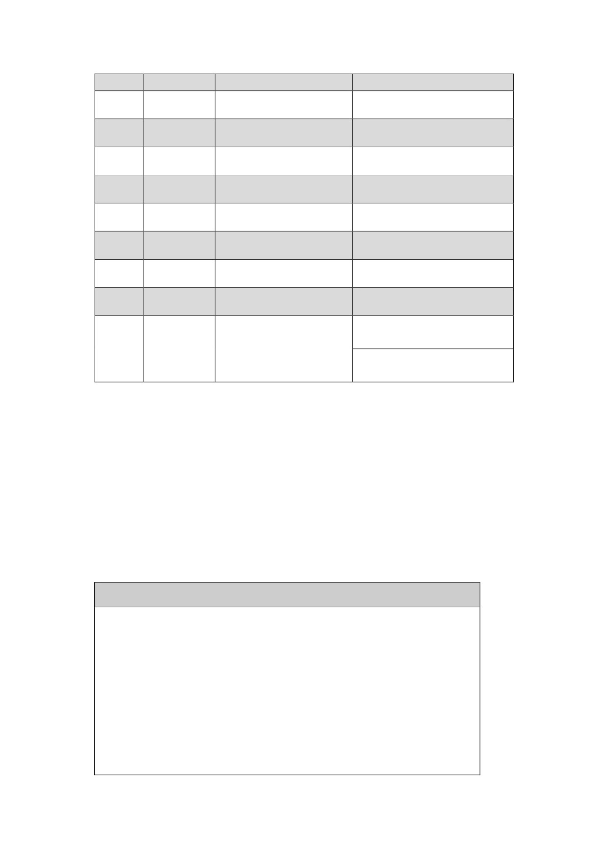
Selection
1:5K
7
STB-7
8
STB-8
9
STB-9
10
STB-10
11
STB-11
12
STB-12
13
STB-13
14
STB-14
0:Do not lock the
Lock control of the
operation keys
15
STB-15
operation keys
1:Lock keys
(Unlock:SET+MODE)
8. Operation and Modification
Caution
z The spindle drive and motor must be reliably grounded, and
PE terminal must be connected with the grounded terminal of
the equipment reliably.
z The power can be connected only after the wiring is correct.
z Emergency stop circuit must be provided to make sure the power
could be stopped at once in case of emergency.
z If a drive alarm is reported, make sure the alarm is cleared
and the spindle enable input signal (EN) is ineffective before
restarting the drive unit.
z After the spindle drive and motor are power off, do not touch
the spindle drive within 5 minutes to avoid electronic shock.
z Be cautious to prevent burning as the temperature may get
higher after the spindle drive and motor running for a period
of time.
8.1 Power Connection
8.1.1 Checking Before Running
After the installation and connection is completed, check the
following items before power on:
z
Whether the type of drive unit HSV-180AS-200 and above is correct
and reliable? Whether the input voltage is correct?
z
Whether the strong power terminal (L1、L2、L3、U、V、W、P、BK、
PE) is correct and reliable? Whether the input voltage is correct?
z
Whether the power lines or motor lines is short circuited or
grounded.
z
Whether the encoder cable connection is correct?
z
Whether the control signal terminal connection is correct?
Whether the polarity and size are proper?
z
Whether the spindle drive and motor are fixed firmly?
8.1.2 Power On Sequence
z For HSV-180AS-035,050,075,100,150,connect the main circuit power
(three-phase AC380V) and external DC 24V power supply. The digital
tube of the spindle drive is light, spindle alarm (ALM) is disconnected,
and the failure chain relay normally-open contact on interface XS5
closed. If an alarm is reported, power the spindle drive off and check
the trouble.
z
For HSV-180AS-200,300,450,connect the drive unit control power
(single-phase AC380V) and external DC 24V power supply. The digital
tube of the spindle drive is light, spindle alarm (ALM) is disconnected,
and the failure chain relay normally-open contact on interface XS5
closed. If an alarm is reported, power the spindle drive off and check
the trouble. If an alarm is not appear, connect the main circuit power
(three-phase AC380V)
z
After 1 second, the spindle enable signal (EN) is received. If the
spindle drive have no faults and the spindle enabling function is
effective, the motor is activated and in the state for running. If
an alarm is reported and the spindle enabling function is ineffective,
the motor is idle. At this time, power off the main circuit power and
check the trouble.
z
In the external speed running mode (analog interface), the PC outputs
the spindle forward (FWD) or spindle reverse (REW) control signal to
spindle drive. And operate PC to send analog command to spindle drive.
The motor runs according to the command.
z
In the position running mode (pulse interface) or the external speed
running mode (pulse interface), the PC to send pulse command to spindle
drive. The motor runs according to the command.
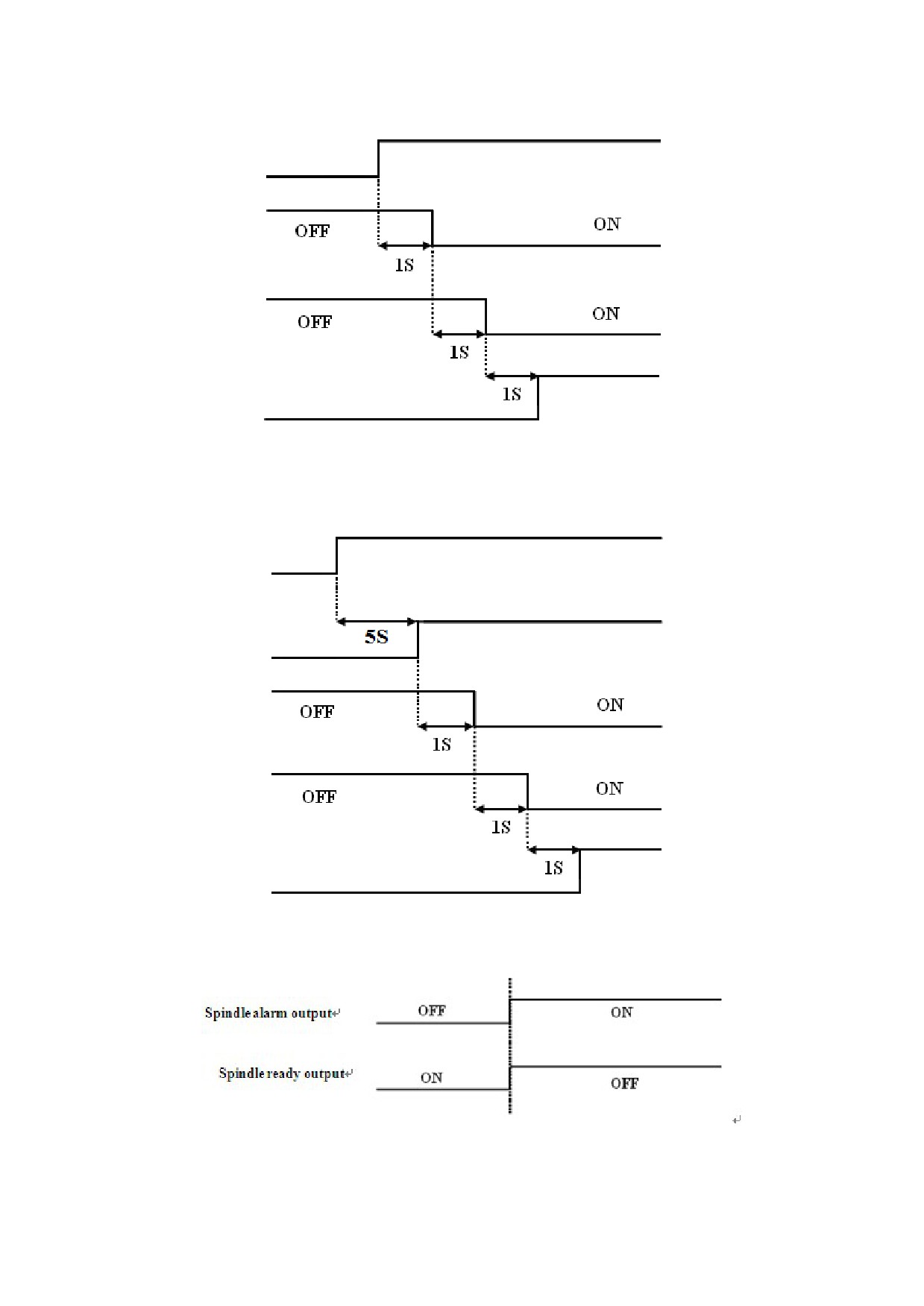
8.1.3 power connection and alarm sequence
Figure 8-1 HSV-180AS-035,050,075,100,150Sequential diagram for
power connection (analog command)
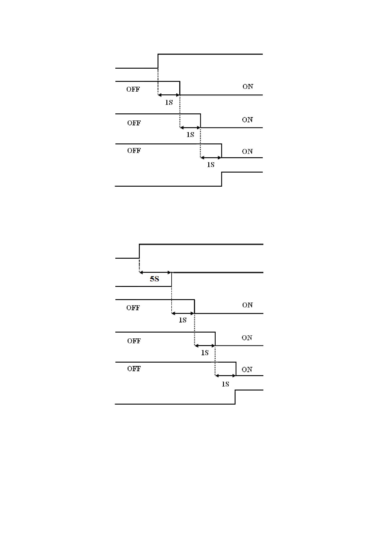
Main circuit power
supply
Spindle ready
output
Spindle enable
input
Spindle
forward/reverse
input
Analog command
Figure 8-2 HSV-180AS-200,300,450Sequential diagram for power
connection (analog command)
Control power
Main circuit power
supply
Spindle ready
output
Spindle enable
input
Spindle
forward/reverse
input
Analog command
Figure 8-3 HSV-180AS-035,050,075,100,150Sequential diagram for
power connection (pulse command)
Main circuit power
supply
Spindle ready
output
Spindle enable
input
Analog command
Figure 8-4 HSV-180AS-200,300,450Sequential diagram for power
connection (pulse command)
Control power
Main circuit power
supply
Spindle ready
output
Spindle enable
input
Analog command
Figure 8-5 Sequential diagram for alarming
Note:
When a spindle drive alarm is reported, cut off the external control
circuit power immediately based on the spindle alarm output signal
(ALM) or the failure chain input/output terminal XS5.
8.1.4 Power Off Sequence
z
For HSV-180AS-035,050,075,100,150,disconnect the main circuit
power (three-phase AC380V) of the spindle drive. If the spindle enable
signal (EN) keep outputting "ON" signal, A-1 (indicates main power
low-voltage) is displayed, the green enable light (EN) on the drive
unit panel is off, and the red alarm light (AL) is on (indicates alarm).
z
For HSV-180AS-200,300,450,firstly disconnect the main circuit power
(three-phase AC380V) of the spindle drive, and then disconnect the
drive unit control power (single-phase AC380V) and external DC 24V
power supply. When spindle detect heavy electricity disconnected, if
the spindle enable signal (EN) keep outputting "ON" signal, A-1
(indicates main power low-voltage) is displayed, the green enable
light (EN) on the drive unit panel is off, and the red alarm light
(AL) is on (indicates alarm).
z
After disconnect the main circuit power, the internal capacitor
storage energy of the spindle drive could not be released immediately.
Do not connect nor disconnect wire within five minutes.
z
Avoid frequently turning on and off the main circuit power in a short
period of time, which may damage the soft-start circuit.
8.1.5. Alarm Clear
There are three methods to clear the alarm:
z Turn off the power (three-phase main power), after the fault source
is cleared; repower the spindle drive to clear the alarm. (Some alarm
can only be cleared by this method).
z Do not turns off the power, after the fault source is cleared, and
enter the auxiliary mode to reset the internal alarm to clear the alarm.
After the alarm is reset, the red alarm light is off (indicating the
alarm is cleared), the spindle alarm (ALM) output is disconnected and
the failure chain relay normally-open contact on the input/output
terminal XS5 is connected.
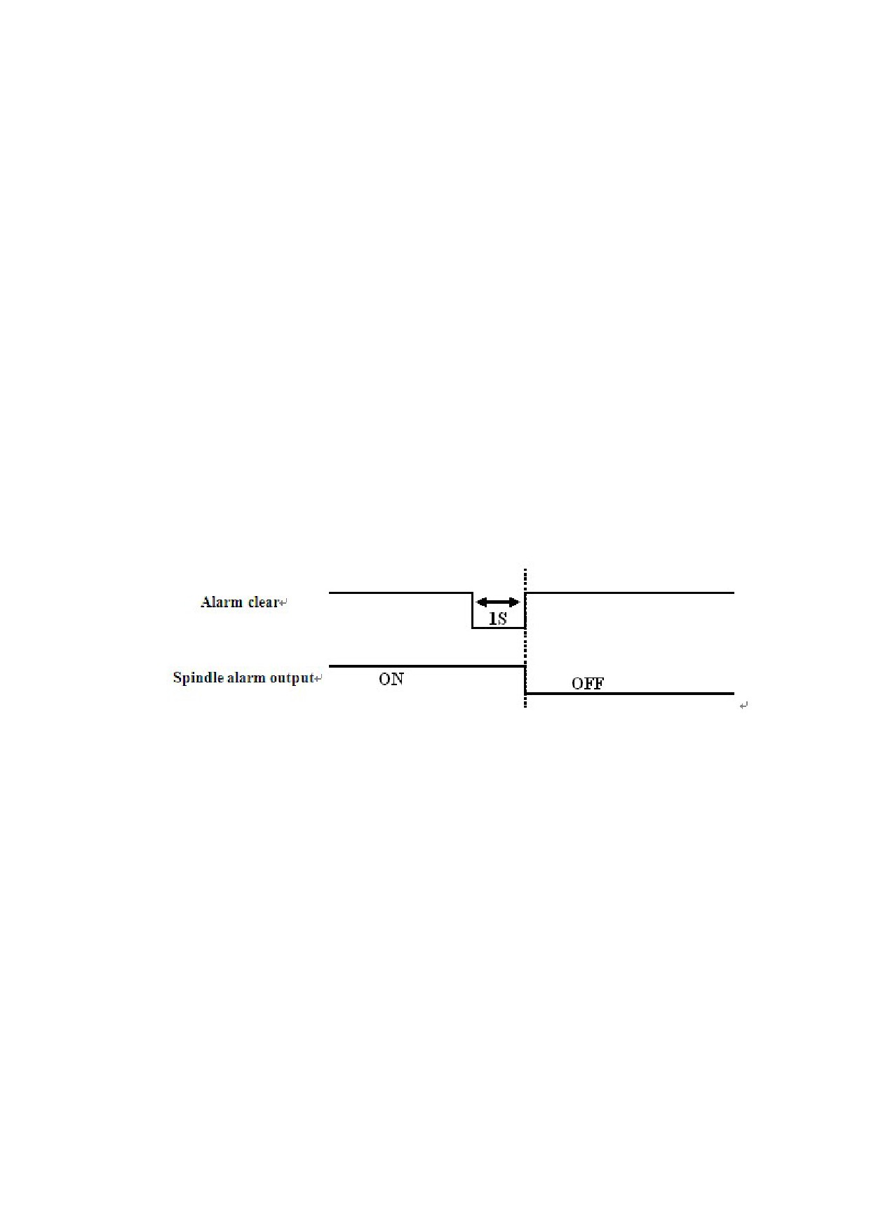
z Do not turns off the power, after the fault source is cleared, reset
the external alarm to clear the alarm via the alarm clear input signal
(ALM_RST), see Figure 8-4. After the alarm is reset, the red alarm
light is off (indicates the alarm is cleared), the spindle alarm (ALM)
output is disconnected and the failure chain relay normally-open
contact on the input/output terminal XS5 is connected.
Figure 8-4 Sequential diagram for external alarm clear
8.2 Trial Operation
Before operating any modes as follows, you must check whether the motor
parameter setting of spindle drive and phase sequence of motor power line
is right. Steps as follows:
1、For HSV-180AS-150 spindle drive and below, disconnect motor coding
cable and motor power line, connect the main circuit power (three-phase
AC380V) of the spindle drive.
2、 For HSV-180AS-200 spindle drive and above, disconnect motor coding
cable and motor power line, connect the main circuit power (single-phase
AC220V) of the spindle drive.
3、Modify control parameters and movement parameters:
Setting STA—0 to 0, STA—6 to 1
According to the spindle drive and type of motor encoder, setting follow
parameters:PA—41,PA--24,PA—25 and PA—59.
4、Changing PA—41 to 1230 after completing setting,, enter auxiliary
parameter setting mode to save parameter, and turn off at last.
5、Connect encoder and power line of motor:
For HSV-180AS-150 and below specifications: only need to connect the
three-phase AC380V of strong electric。
For HSV-180AS-200 and above specifications:Firstly connect single-phase
AC220V of control power,and then connect the three-phase AC380V of strong
electric。
6、If the spindle motor free running or alarm(A30 or A33)after power
on and enable,motor phase sequence reversed,exchangeable motor power
line V, W phase sequence。
Note:Operating 2 steps above, the motor shaft must be no load.
8.2.1 JOG Running Mode
1、For wiring, see Figure 5.8 in Chapter 5
2、 For HSV-180AS-150 spindle drive and below ,disconnect motor coding
cable and motor power line, connect the main circuit power (three-phase
AC380V) of the spindle drive.
For HSV-180AS-200 spindle drive and above, disconnect motor coding cable
and motor power line, connect the main circuit power (single-phase AC220V)
of the spindle drive.
3、 Modify control parameters and movement parameters:
Setting STA—0 to 0;Setting STA—6to 1;
According to the type of spindle drive, setting follow parameters STB--1
(IM:0,PM:1);
Setting PA—41to 2003,PA—24,PA—25 and PA—59
4、Save the parameter to EEPROM after setting PA—41to 1230. Turn off the
power, wait for 30seconds
5、Connect encoder and power line of motor:
For HSV-180AS-150 and below specifications: only need to connect the
three-phase AC380V of strong electric。
For HSV-180AS-200 and above specifications:Firstly connect si ngle-phase
AC220V of control power,and then connect the three-phase AC380V of strong
electric。
6、Connect the main circuit power (three-phase AC380V) of the spindle drive.
If there are no alarms or abnormal situation, the green enable lamp (EN)
is light, which indicates the drive is working properly. The motor is
activated and in the zero speed state.
7、In the auxiliary mode, select the JOG mode, and JOG-- is displayed
through the digital cube. Press
S
to enter into the JOG mode. RUN-- is
displayed through the digital cube. Press and hold
↑
, the servo motor
runs at the JOG speed. Release
↑
, and then the motor stops and enters
the zero-speed state. Press and hold
↓
, the motor runs at the JOG speed
in the opposite direction. Release
↓
, and then the motor stops and enters
the zero-speed state.
8.2.2 Internal Speed Running Mode
1、For wiring, refer to Figure 5.8 in Chapter 5
2、For HSV-180AS-150 spindle drive and below ,disconnect motor coding
cable and motor power line, connect the main circuit power (three-phase
AC380V) of the spindle drive.
For HSV-180AS-200 spindle drive and above ,disconnect motor coding cable
and motor power line, connect the main circuit power (single-phase AC220V)
of the spindle drive.
3、 Modify control parameters and movement parameters:
Setting STA-0to 0;STA-6to 1
Setting PA—41to 2003;PA—23to3;
Setting PA—24;PA—20to 0;
According to the type of spindle drive, setting parameter STB--1(IM:
0,PM:1);
Setting PA—25 and PA--59;
4、Save the parameter to EEPROM after setting PA—41to 1230. Turn off the
power, wait for 30seconds
5、 Connect encoder and power line of motor:
For HSV-180AS-150 and below specifications: only need to connect the
three-phase AC380V of strong electric。
For HSV-180AS-200 and above specifications:Firstly connect single-phase
AC220V of control power,and then connect the three-phase AC380V of strong
electric6.
6、If there are no alarms or abnormal situation, the green enable lamp
(EN) is light, which indicates the spindle drive is operating normal. The
motor is activated and in the zero speed state.
7、Set the movement parameter PA-20 (internal speed). Press
S
to confirm,
and then the motor will run at the specified speed.
8.2.3 External Speed Running Mode (Analog interface)
1、For wiring, see Figure 5.8.2 in Chapter 5.
2、 For HSV-180AS-150 spindle drive and below ,disconnect motor cable and
motor power line, connect the main circuit power (three-phase AC380V) of
the spindle drive.
For HSV-180AS-200 spindle drive and above, disconnect motor coding cable
and motor power line, connect the main circuit power (single-phase AC220V)
of the spindle drive.
3、Modify control parameters and movement parameters:
Setting STA-0to 0;STA-6to0;PA—23to 1
According to the type of spindle drive, setting parameter STB--1(IM:
0,PM:1);
Setting PA—41to 2003;PA—24,PA—25and PA--59
Setting PA—7 and PA—8
4、Save the parameter settings to EEPROM after setting PA—41to 1230. Turn
off the power, wait for 30seconds。
5、 Connect encoder and power line of motor:
For HSV-180AS-150 and below specifications: only need to connect the
three-phase AC380V of strong electric。
For HSV-180AS-200 and above specifications:Firstly connect single-phase
AC220V of control power,and then connect the three-phase AC380V of strong
electric。
6、 Verify no alarm or abnormal condition is reported. The green enable
lamp (EN) is on, which indicates the spindle drive is working properly.
The motor is activated and in the zero speed state.
7、Use PC outputs forward or reverse control signal to the third pin (FWD)
and the forth pin (REW) and outputs analog signal to the 27, 28, 12, 13
pin (GNDAM, AN+, AN-) on the command input/output interface XS4. The motor
rotate forward or reverse.
8.2.4 External Speed Running Mode (Pulse interface)
1、For wiring, see Figure 5.8.3 in Chapter 5.
2、For HSV-180AS-150 spindle drive and below ,disconnect motor coding
cable and motor power line, connect the main circuit power (three-phase
AC380V) of the spindle drive.
For HSV-180AS-200 spindle drive and above ,disconnect motor coding cable
and motor power line, connect the main circuit power (single-phase AC220V)
of the spindle drive.
3、Modify control parameters and movement parameters::
Setting STA-0 to 0;STA-6to0;PA—23to 2;
According to the type of spindle drive, setting parameter STB--1(IM:
0,PM:1);
Setting PA—41to2003;
Setting PA—24, PA—25,PA—59and PA—22.
4、Save the parameter to EEPROM after setting PA—41to 1230. Turn off the
power, wait for 30seconds
5、Connect encoder and power line of motor:
For HSV-180AS-150 and below specifications: only need to connect the
three-phase AC380V of strong electric。
For HSV-180AS-200 and above specifications:Firstly connect single-phase
AC220V of control power,and then connect the three-phase AC380V of strong
electric。
6、If there are no alarms or abnormal situation, the green enable light
(EN) is on which indicates the spindle drive working properly. The motor
is activated and in the zero speed state.
7、PC sends pulse command to the 14、15、16、17(GNDAM、AN+、AN-) pins
on the command input/output interface XS4. The motor runs according to
the command.
8.2.5 Position Running Mode (Pulse interface)
1、For wiring, see Figure 5.8.1 in Chapter 5.
2、For HSV-180AS-150 spindle drive and below ,disconnect motor coding
cable and motor power line, connect the main circuit power (three-phase
AC380V) of the spindle drive.
For HSV-180AS-200 spindle drive and a above, disconnect motor coding cable
and motor power line, connect the main circuit power (single-phase AC220V)
of the spindle drive.
3、Modify control parameters and movement parameters:
Setting STA-0to 0;STA-6to 0;PA—23 to 0;
Setting PA--24
According to the type of spindle drive, setting parameter STB--1(IM:
0,PM:1);
Setting PA—41to2003;
Setting PA—24, PA—25,PA—59and PA—22.
4、Save the parameter to EEPROM after setting PA—41to 1230. Turn off the
power, wait for 30seconds
5、Connect encoder and power line of motor:
For HSV-180AS-150 and below specifications: only need to connect the
three-phase AC380V of strong electric。
For HSV-180AS-200 and above specifications:Firstly connect single-phase
AC220V of control power,and then connect the three-phase AC380V of strong
electric。
6、If there are no alarms or abnormal situation, the green enable light
(EN) is on, which indicates the spindle drive is working properly. The
motor is activated and in the zero speed state.
7、The PC sends pulse command to the 14,15,16,17 pins on the command
input/output interface XS4. The motor runs according to the command.
8.2.6 Switching Between External Speed Running Mode (Analog
Interface) and Position Running Mode
1、For wiring, see Figure 5.8.4 in Chapter 5.
2、 For HSV-180AS-150 spindle drive and below , disconnect motor coding
cable and motor power line, connect the main circuit power (three-phase
AC380V) of the spindle drive.
For HSV-180AS-200 spindle drive and above, disconnect motor coding cable
and motor power line, connect the main circuit power (single-phase AC220V)
of the spindle drive.
3、Modify control parameters and movement parameters:
Setting STA-0to 0;STA-6to 0;PA—23to0;
Setting PA--24
According to the type of spindle drive, setting parameter STB--1(IM:
0,PM:1);
Setting PA—41to2003;
Setting PA—25, PA—59,PA—7,PA—8 and PA—22.
4、 Save the parameter to EEPROM after setting PA—41to 1230. Turn off
the power, wait for 30seconds
5、Connect encoder and power line of motor:
For HSV-180AS-150 and below specifications: only need to connect the
three-phase AC380V of strong electric。
For HSV-180AS-200 and above specifications:Firstly connect single-phase
AC220V of control power,and then connect the three-phase AC380V of strong
electric。
6、If there are no alarms or abnormal situation, the green enable light
(EN) is on, which indicates the spindle drive is working properly. The
motor is activated and in the zero speed state.
7、Switching between external speed running mode (analog interface) and
position running mode is controlled by the 26 pin (Mode_SW) on interface
XS4 (indicating the switch input for control mode switching ). When the
Mode_SW is OFF, the spindle runs under the analog speed mode. Use PC to
output forward or reverse control signal to the third pin(FWD)and the
forth pin(REW) on XS4 and output analogue signal to the 27, 28, 12, 13
pin (GNDAM、AN+、AN-)on XS4. The motor rotates forward or reverse. When
the Mode_SW is ON, the spindle runs under the position running mode.
Operate PC outputs pulse command to the 14, 15, 16, 17 pin (CP+、CP-、
DIR+、DIR-) on the XS4 interface. The motor run according to the command.
8.2.7 Switching Between External Speed Running Mode(Pulse
Interface) and Position Running Mode(Pulse Interface)
1、For wiring, see Figure 5.8.5 in Chapter 5.
2、For HSV-180AS-150 spindle drive and below , disconnect motor coding
cable and motor power line, connect the main circuit power (three-phase
AC380V) of the spindle drive.
For HSV-180AS-200 spindle drive and above ,disconnect motor coding cable
and motor power line, connect the main circuit power (single-phase AC220V)
of the spindle drive.
3、Modify control parameters and movement parameters:
Setting STA-0to 0;STA-6to 0;STA-8 to 1
Setting PA—23 to 1
According to the type of spindle drive, setting parameter STB--1(IM:
0,PM:1);
Setting PA—41to2003;
Setting PA—24, PA—25,PA—59and PA—22.
Save the parameter to EEPROM after setting PA—41to 1230. Turn off the
power, wait for 30seconds。
5、Connect encoder and power line of motor:
For HSV-180AS-150 and below specifications: only need to connect the
three-phase AC380V of strong electric。
For HSV-180AS-200 and above specifications:Firstly connect single-phase
AC220V of control power,and then connect the three-phase AC380V of strong
electric。
6、If there are no alarms or abnormal situation, the green enable light
(EN) is on, which indicates the spindle drive is working properly. The
motor is activated and in the zero speed state.
7、Switching between external speed running mode (analog interface) and
position running mode is controlled by the 26 pin (Mode_SW) on
interfaceXS4 (indicates the switch input for control mode switching) .
When the Mode_SW is OFF, the spindle runs under the external speed mode.
Use PC to output pulse command to the14, 15, 16, 17 pin (CP+、CP-、DIR+、
DIR-) on XS4. The motor runs according to the command. When the Mode_SW
is ON, the spindle runs under the position running mode. Use PC to output
pulse command to the 14, 15, 16, 17 pin (CP+、CP-、DIR+、DIR-) on the
interface XS4. The motor runs according to the command.
8.2.8 Spindle Orientation
1、For wiring, see Figure 5.8 Standard wiring diagram in Chapter 5.
2、 For HSV-180AS-150 spindle drive and below , disconnect motor coding
cable and motor power line, connect the main circuit power (three-phase
AC380V) of the spindle drive.
For HSV-180AS-200 spindle drive and above ,disconnect motor coding cable
and motor power line, connect the main circuit power (single-phase AC220V)
of the spindle drive.
3、Modify control parameters and movement parameters:
Setting STA-0to 0;STA-6to 0;
Setting PA—23 to 1 or 2
According to the type of spindle drive, setting parameter STB--1(IM:
0,PM:1);
Setting PA—41to2003;
Setting PA—24, PA—59.
According to the actual operation, set PA—37, PA—38, PA—39 PA—47,
STA-13 , STA-14 and STA-15
4、Save the parameter to EEPROM after setting PA—41to 1230. Turn off the
power, wait for 30seconds
5、Connect encoder and power line of motor:
For HSV-180AS-150 and below specifications: only need to connect the
three-phase AC380V of strong electric。
For HSV-180AS-200 and above specifications:Firstly connect single-phase
AC220V of control power,and then connect the three-phase AC380V of strong
electric。
6、If there are no alarms or abnormal situation, the green enable light
(EN) is on which indicates the spindle drive is working properly. The motor
is activated and in the zero speed state.
7、Output the control signal for spindle orientation begin to the 25 pin
(ORN) on the XS4 command input/output interface. The spindle motor
orientate at the preset spindle orientation speed. When the deviation
between the actual position and preset orientation position is equal or
less than the preset range for spindle orientation finished, the 30 pin
(ORN_FIN) on the XS4 outputs signal for spindle orientation finished. When
the output signal is absent, the state of spindle orientation is finished.
8.2.9 Spindle Indexing Incremental Orientation
1、For wiring, see Figure 5.8 Standard wiring diagram in Chapter 5.
2、For HSV-180AS-150 spindle drive and below , disconnect motor coding
cable and motor power line, connect the main circuit power (three-phase
AC380V) of the spindle drive.
For HSV-180AS-200 spindle drive and above, disconnect motor coding cable
and motor power line, connect the main circuit power (single-phase AC220V)
of the spindle drive.
3、Modify control parameters and movement parameters:
Setting STA-0to 0;STA-6to 0;