Series HSV-180AS AC Spindle Drive. User Manual (V1.00 2012.4) - page 4
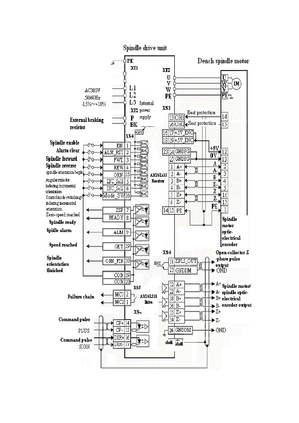
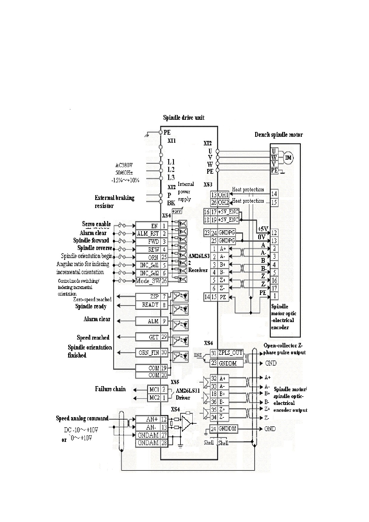
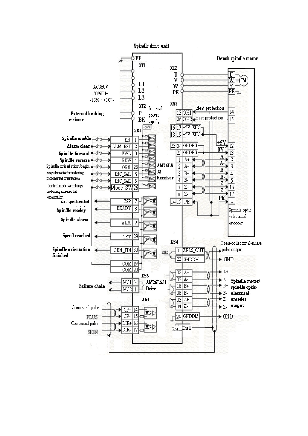
5.8.2 Standard Wiring for External Speed Control Mode (Analog
Interface)
Figure 5-41 Standard wiring for external speed control mode (analog
interface)
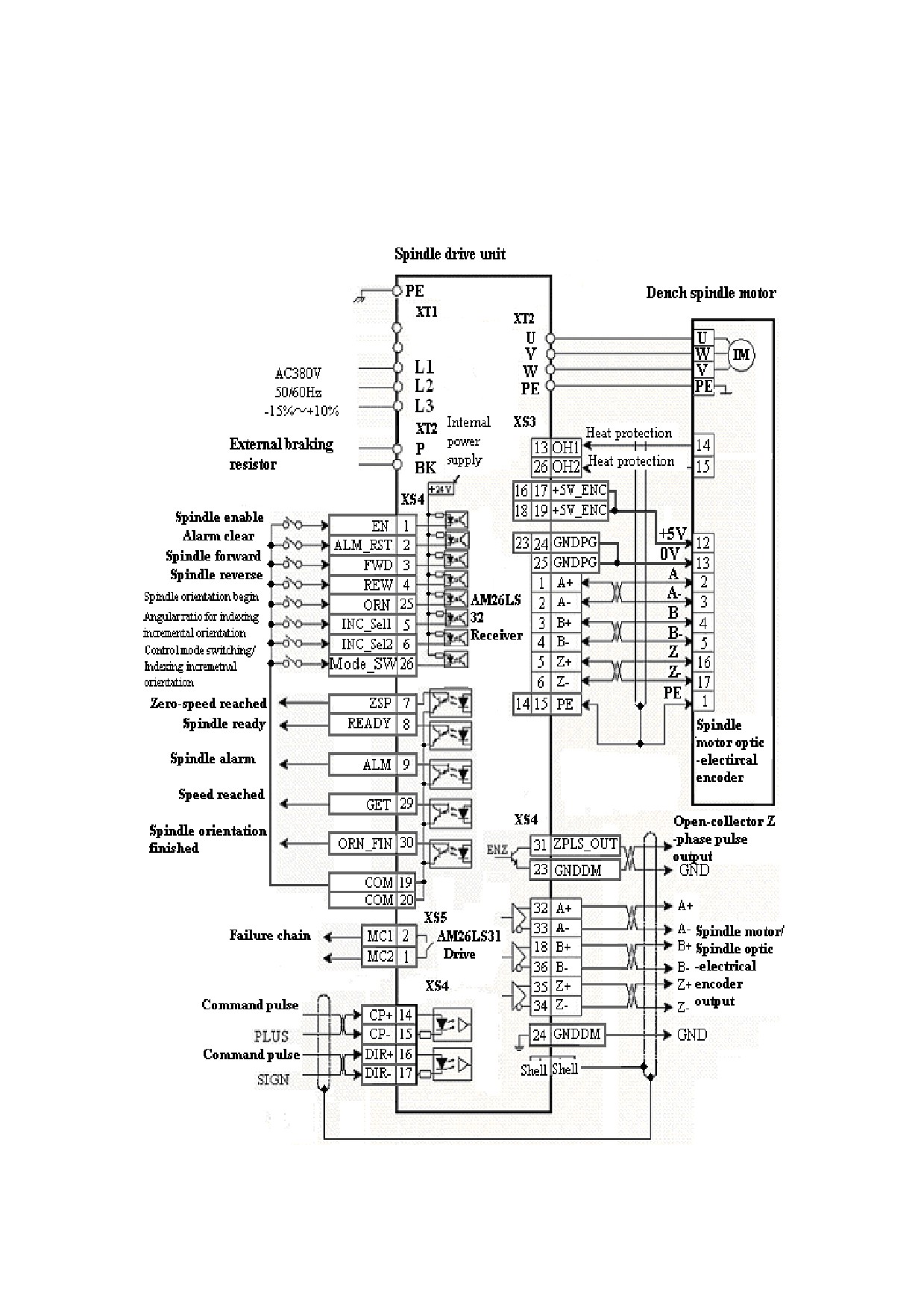
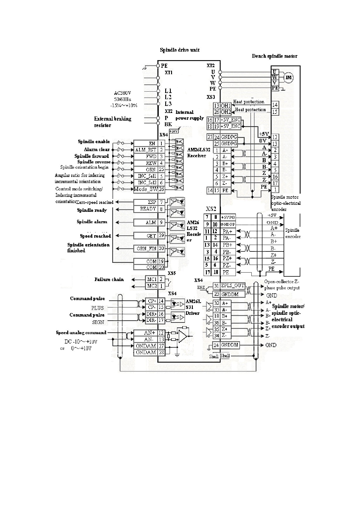
5.8.3 Standard Wiring for External Speed Control Mode (Pulse
Interface)
Figure 5-42 Standard wiring for external speed control mode (pulse interface)
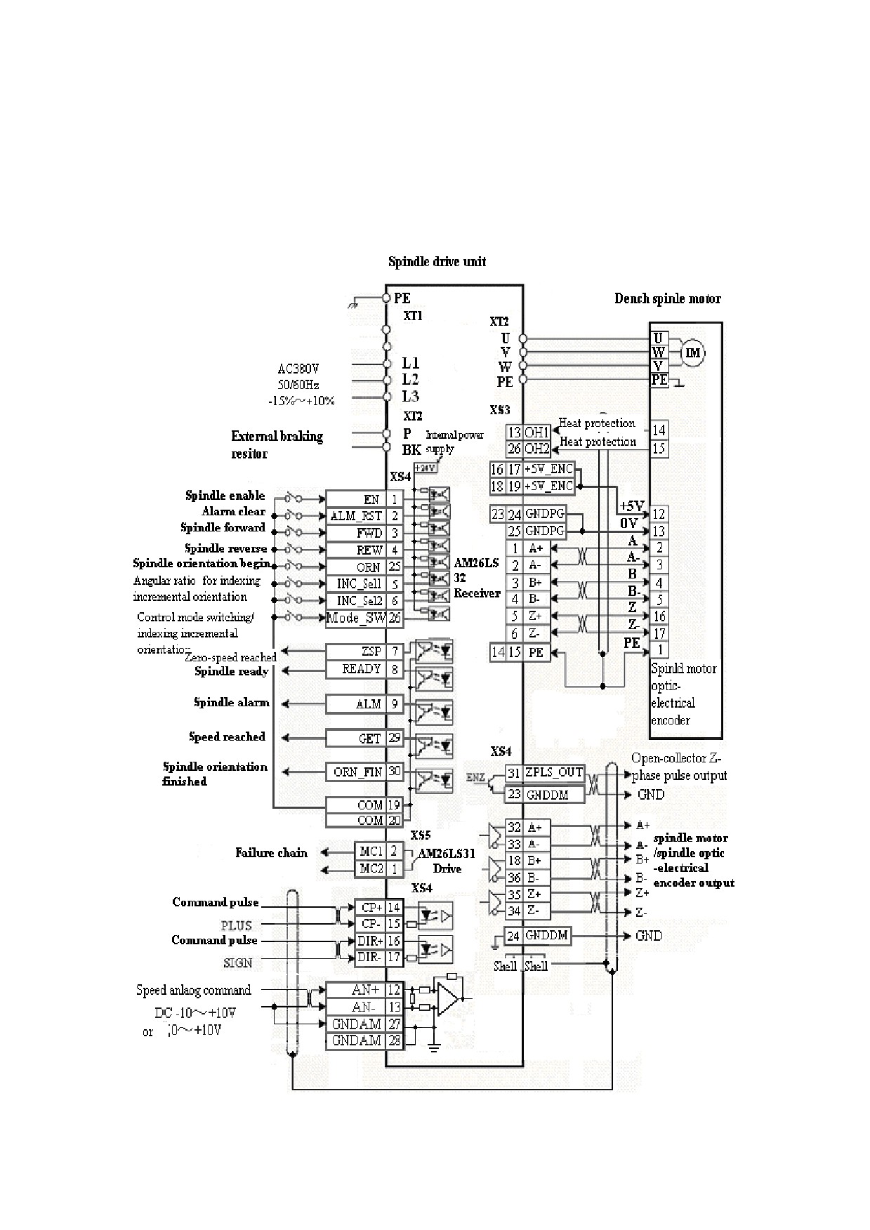
5.8.4 Standard Wiring for the Switching Between External Speed
Control Mode (Analog Interface) and Speed Control Mode (Pulse
Interface)
5.8.5 Standard Wiring For the Switching Between External Speed
Control Mode (Pulse Interface) and Speed Control Mode (Analog
Interface)
5.8.6 Standard Wiring for Spindle Encoder
Figure 5-45 Standard wiring for spindle encoder
6. Operation and Display
6.1 Overview
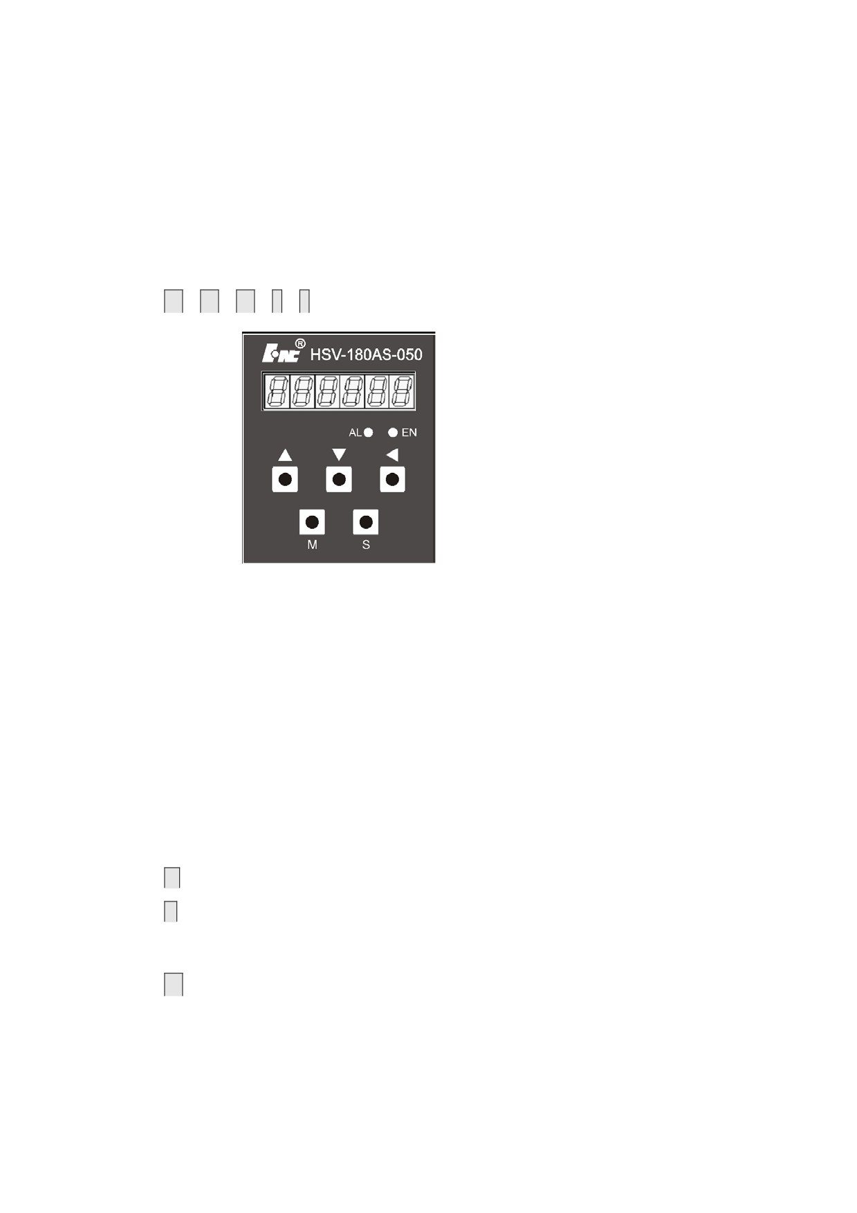
1. The drive unit panel consists of 6 LED digital displays, 5 buttons
↑
、
↓
、
←
、
M
、
S
, and 2 light-emitting diodes.
Figure 6-1 Digital display of series HSV-180AS spindle drive unit
z The 6 LED digital displays are used to display various statuses
and set parameters.
z The red light-emitting diode is an alarming lamp (AL). When it is
on, it means "drive unit alarm". The green light-emitting diode
is an enable lamp (EN). When it is on, it means "spindle drive
enable"
z The function of each button is as follows:
M:used for main menu mode switching
S
:used for entering into the secondary menu, returning to the main
menu
mode, and input confirmation
↑
:used for an increase in number and value, or moving to the next
option
↓
:used for a decrease in number and value, or moving back to the
previous option
←
:used for shifting
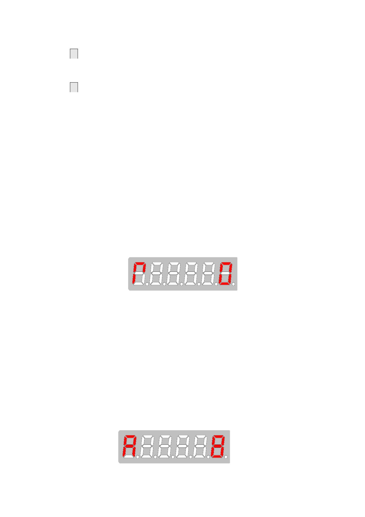
2. After the control power supply of the spindle drive is connected,
the six LED digital displays on the panel all display "8", and change
to "R O" a second later.
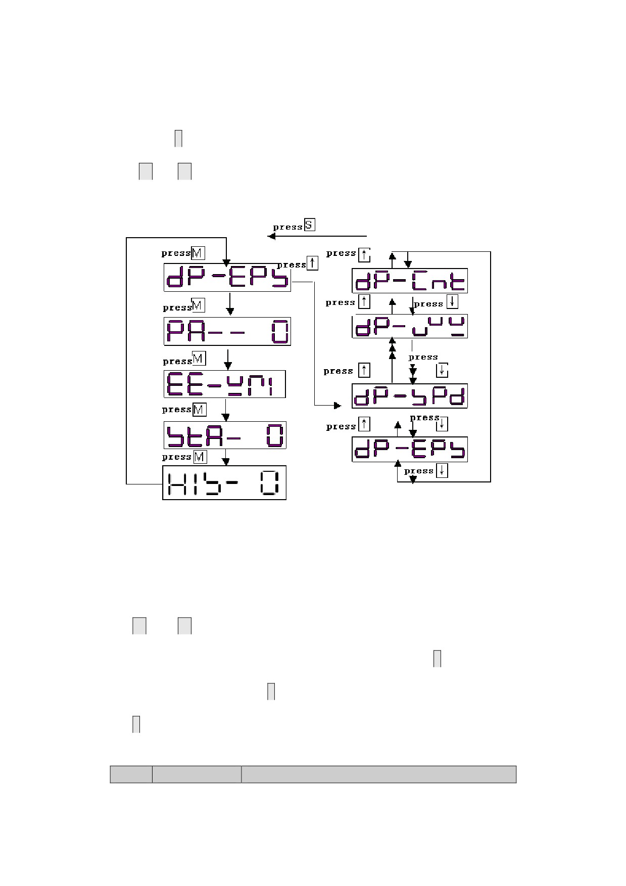
3. Users must operate based on the multi-level menus. The first-level
menu is the main menu which includes five operation modes: display
mode, movement parameter mode, auxiliary mode, control parameter mode,
and alarm history display mode. Each operation mode contains a
secondary menu.
Figure 6-2 R
0 display
4. The 6-bit LED digital tube displays various status and data of the
system. If the first bit of the digital tube displays A , and at the
same time the red light-emitting diode is on, an alarm is generated.
The follow-up bit of the digital tube displays the alarm code. After
the process of fault diagnosis and troubleshooting, you can reset the
system by the alarm reset mode under the auxiliary mode or cutting
off the power and then re-power to the spindle drive. When the red
light-emitting diode is off, the system is reset.
Figure 6.3 A8 Alarm display
6.2 Operation in the Display Mode
1. Press
M
to switch the operation mode on the main menu”, and press
↑
and
↓
to enter the secondary menu for the display mode.
Figure 6-4 Main menu for the display mode
6.3 state surveillance mode
HSV-180AS spindle drive contains 21 types of display modes(see table 6.1).
Press
↑ and
↓
to select a display mode as required. The display status
can only be viewed and cannot be modified or set. Press
S
to display the
detailed status, then press
S
to return to the secondary menu, and then
press
M to return to the main menu.
Table 6-1 Meaning of each symbol in the display mode
NO.
Symbol
Description
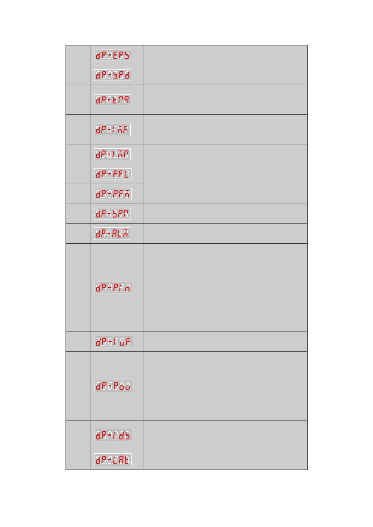
Display the speed tracking error
1
unit:pulse
2
Display the actual speed (unit: 1r/m)
Display the actual torque current(Effective
3
value )
unit:0.1A
Display the actual magnetic field current
4
(Effective value)
unit:0.1A
Display the magnetic field current command
5
unit:0.1A
6
Display the actual position of motor
unit:pulse
7
Actual position = DP-PFM * 10000 + DP-PFL
Display speed command
8
unit: 1r/min
9
Display alarm status
Display switch-value input status
PIN.1:spindle drive enable
PIN.2:alarm status reset
PIN.3:CW control
10
PIN.4:CCW control
PIN.5:INC_Sel1
PIN.6:INC_Sel2
PIN.7:spindle orientation control
PIN.8:control mode switch
Display the actual feedback value of the
11
U-phase current
Display switch-value output status
POU.1:zero-speed reached
POU.2:drive system ready
12
POU.3:alarm output
POU.4:reserved
POU.5:speed reached
POU.6:spindle orientation-finished
Display the actual load current(Effective
13
value )
unit:0.1A
Display the number of the feedback pulse of
14
the spindle motor optic-electrical encoder
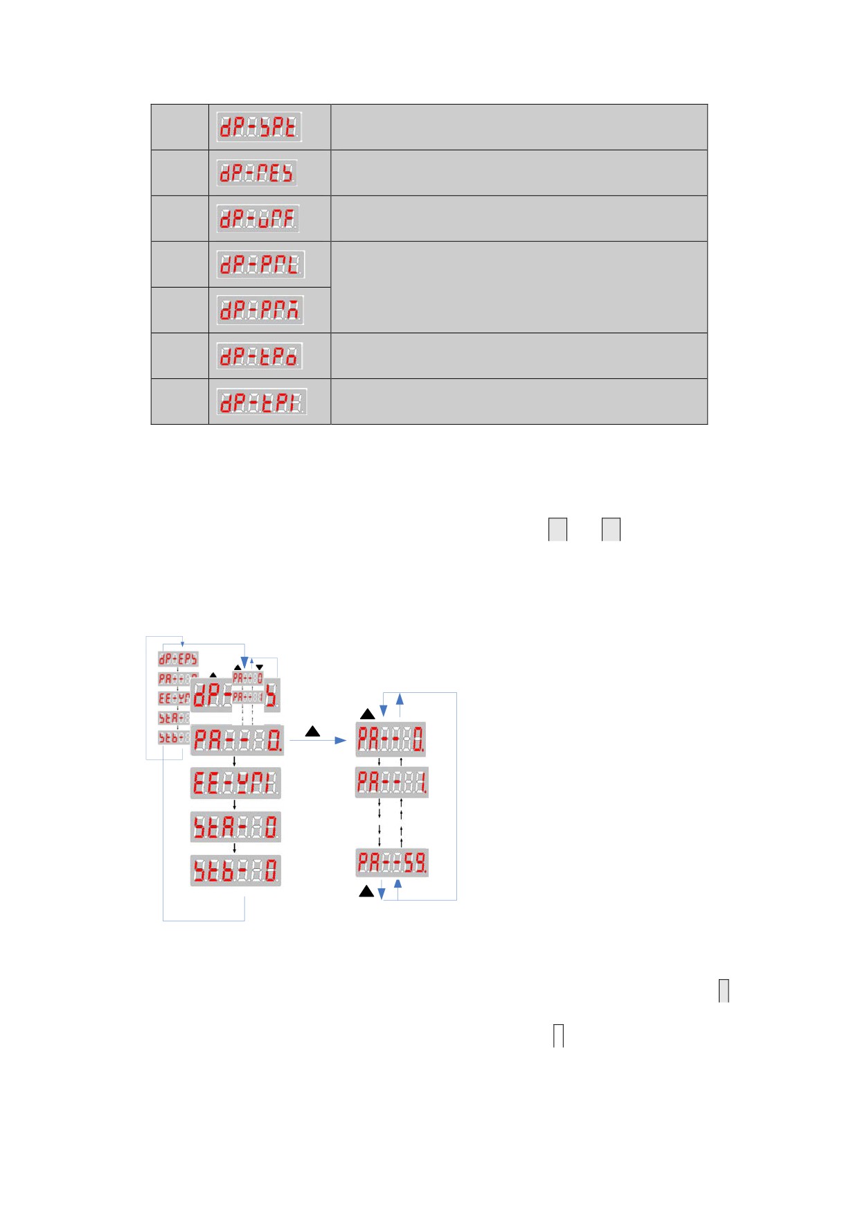
Display the number of feedback pulse of the
15
spindle encoder
16
Display the speed deviation
Display voltage reference output
17
18
Display position command
unit:pulse
19
Actual position = DP-PRM * 10000 + DP-PRL
Display the single-turn absolute position
20
value of Absolute encoder
21
Reserved
6.4 Operation in the Movement Parameter Mode
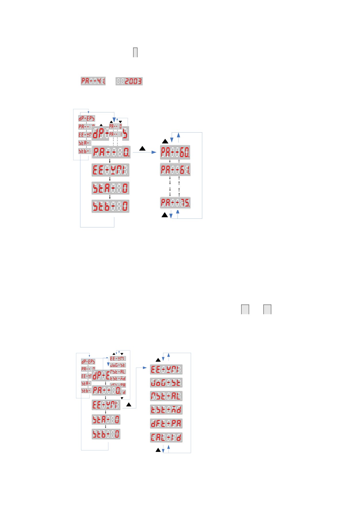
1. On the main menu, select "PA--0", and press
↑
and
↓
to enter the
secondary menu for the movement parameter mode.
2. Series HSV-180AS spindle drive contains 60 movement parameters.
Figure 6-6 Secondary menu for the movement parameter mode
3. If the modified or changed parameters need to be saved, press
M
to switch to the "EE-WRI" mode, and then press
S
to save them to the
EEPROM in the spindle drive. When the saving is finished, "FINISH"
is displayed. Press
M
to re-select the movement parameter mode or other
modes. HSV-180AS spindle drive contains 16 types of display modes
z
Set
to
,could open extension movement parameter mode
HSV-180ASspindle unit have 16 extension parameters
Figure 6-5 Secondary menu for extension movement parameter mode
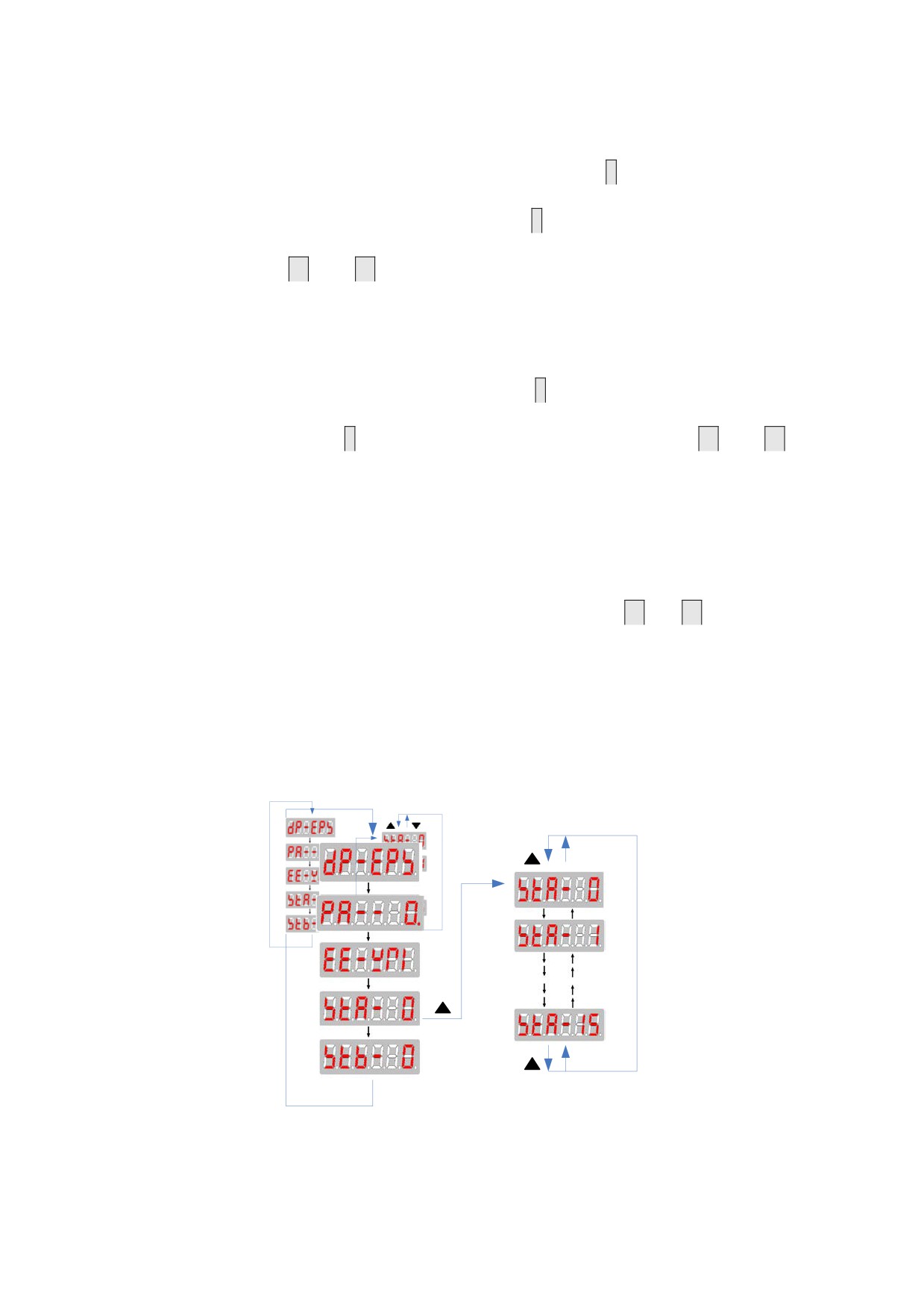
6.5Operation in the Auxiliary Mode
1. On the main menu, select“EE-WRI”, and press
↑
and
↓
to enter
the secondary menu for the auxiliary mode.
2. Series HSV-180AS spindle drive contains 6 types of auxiliary modes

Figure 6-8 Secondary menu for the auxiliary mode
A.
EEPROM mode: This method is effective only during the parameter
changes and settings. If changing or setting parameters, you
should firstly set
to
, then save the new
parameter values by pressing
S
in this mode. When “FINISH” is
displayed, the parameter change and setting is completed. Press
M
to switch to another mode, or press
↑
and
↓
to select other
operations in the auxiliary mode.
B.
JOG mode: This mode is effective only in JOG running. When the JOG
speed parameter PA-21 is a non-zero value, on the main menu, press
M
to select the auxiliary mode, and press
↑
and
↓
to select the
JOG running mode. “JOG---” is displayed through the digital
display. Press
S
, “R --- ”is displayed, which indicates that the
system enters into the running state. Press and hold
↑
, then the
spindle drive and motor run at the speed specified by PA-21. Press
↓
, then the motor run at the speed specified by PA-21 in the
opposite direction. Release the
↑
or
↓
to stop the motor. Press
S
to return to the auxiliary mode. Press
M
to switch to another
mode, or press
↑
and
↓
to select other operations in the
auxiliary mode.
C.
Alarm resetting mode: When the spindle drive unit generates an
alarm, press
S
to reset the system in this mode. If the fault is
cleared, the spindle drive unit returns to normal. Press
M
to
switch to another mode, or press
↑
and
↓
to select other
operations in the auxiliary mode.
D. Default restoration mode: This mode is used to set the parameters
to the default values. In this mode, press
S
to restore system
parameters to default values. Press
M
to switch to another mode,
or press
↑
and
↓
to select other operations in the auxiliary
mode.
E. Alarm history clearance mode: This mode is used to clear alarm
history records. In this mode, press
S to clear the alarm history
records. Press
M
to switch to another mode, or press
↑
and
↓
to select other operations in the auxiliary mode.
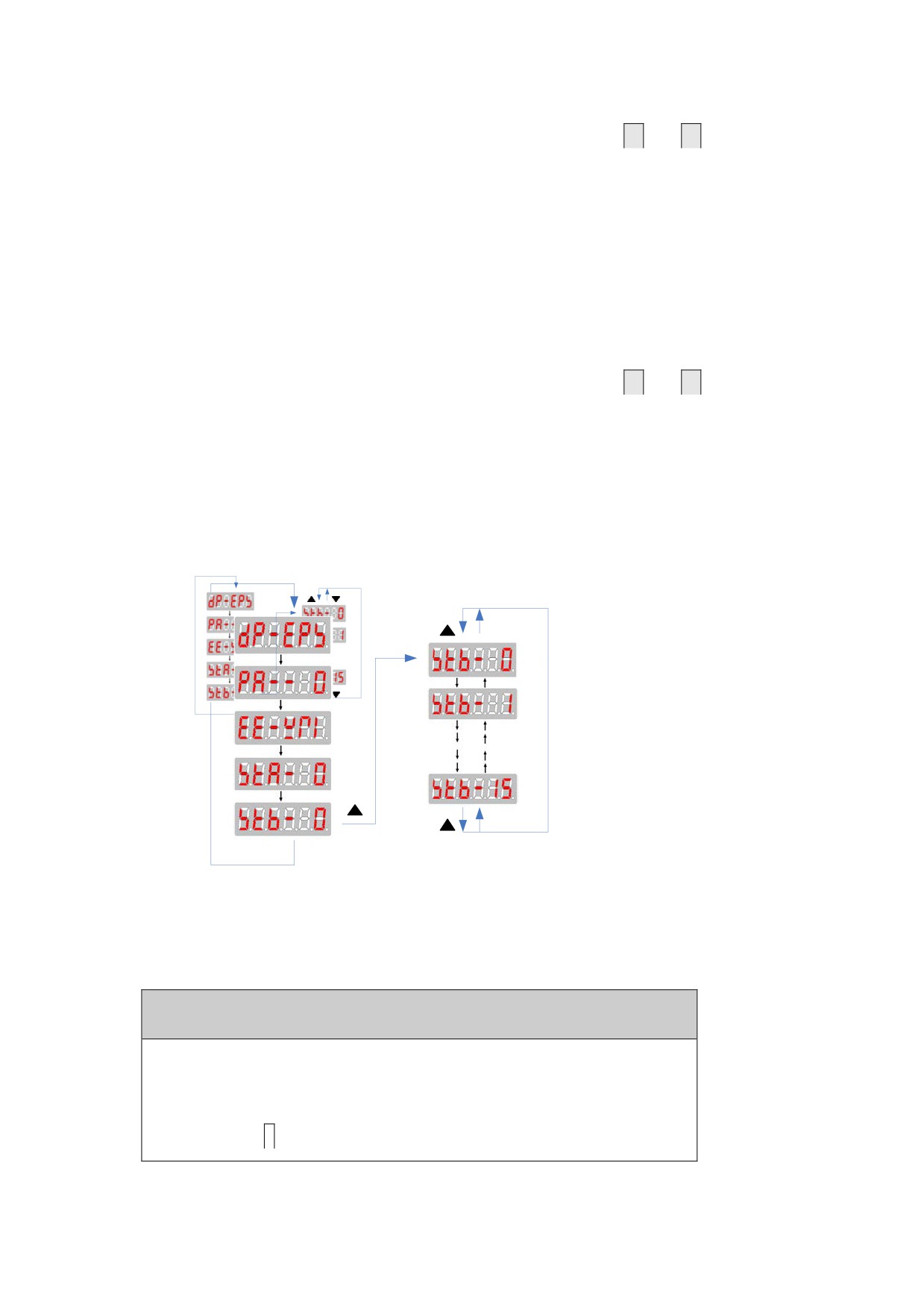
6.6 Operations in the Control Parameter Mode
1. On the main menu, select “STA-0”, and press
↑
and
↓
to enter
the secondary menu for the control parameter mode.
2. Series HSV-180AS spindle drive contains 16 types of control
parameters.
Figure 6-9 Secondary menu for the control parameter mode
1. On the main menu, select “STA-0”, and press
↑
and
↓
to enter
the secondary menu for the control parameter mode.
2. Series HSV-180S spindle drive contains 16 types of control
parameters.
6.7Operation in the Auxiliary Mode
1. On the main menu, select “STA-0”, and press
↑
and
↓
to enter
the secondary menu for the control parameter mode.
2. Series HSV-180AS spindle drive contains 16 types of control
parameters.
Figure 6-10 Secondary menu for the auxiliary mode
6.8 Control Parameter Setting and Saving
Caution
z The control parameter setting cannot take effect
immediately. The new parameter can be confirmed by
pressing
S
only in the "EE-WRI" of auxiliary mode, and it
takes effect after restarting the spindle drive.
z
Wrong settings may cause improper operation that leads to
accidents.
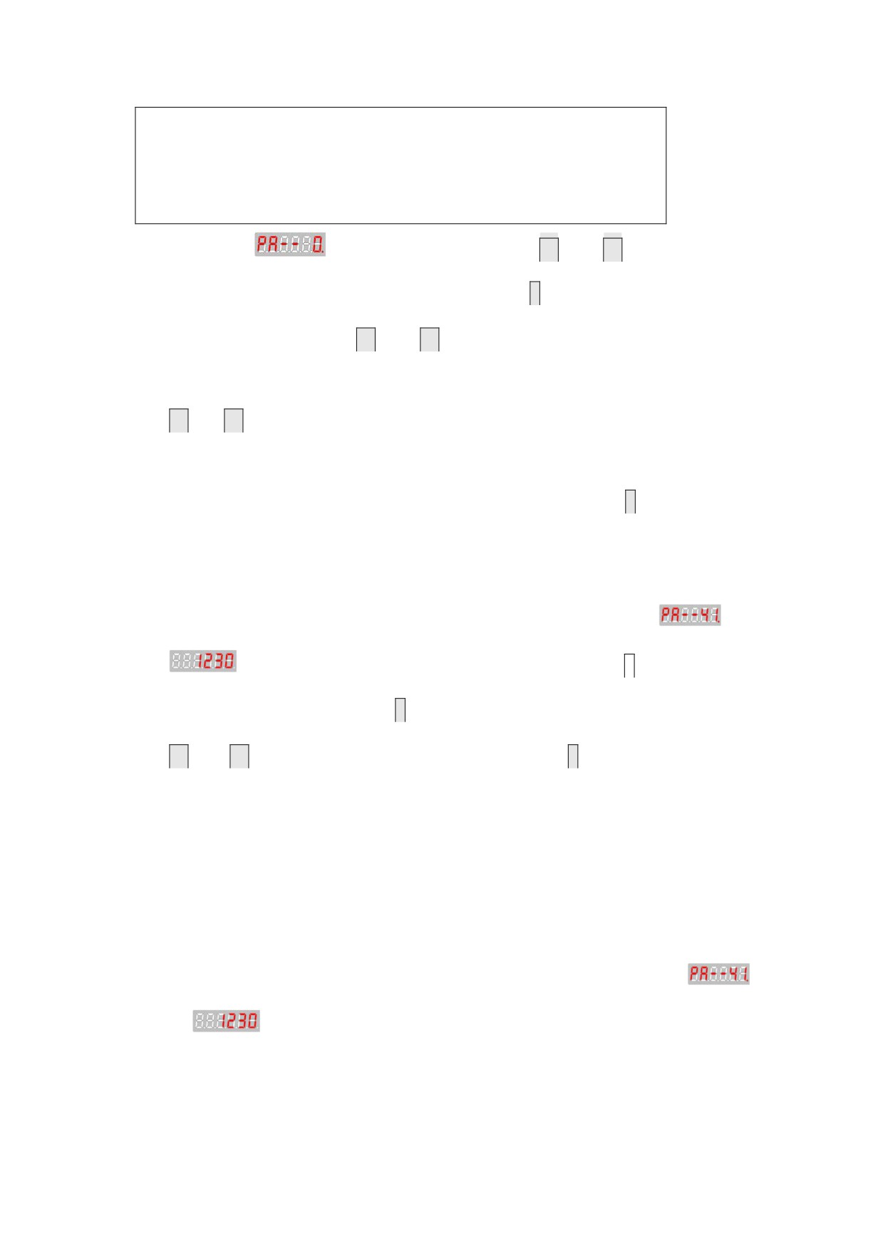
1. Select
on the main menu, press
↑
and
↓
to select a
control parameter number, and then press
S
to display the value of
the parameter. Press
↑
and
↓
to change the parameter value.
2. The parameter value increase or decrease 1 every time you press
↑
or
↓
respectively.
3.After the parameter modification is completed,. the corresponding
decimal point on the LED digital tube light, press
S
to return to
the control parameter mode menu.
3. The control parameter setting cannot take effect immediately. If
changing or setting parameters, you should firstly set
as
, then save the parameter change by pressing
S
to return to
the main menu and pressing
M
to select the auxiliary mode. Then press
↑
and
↓
to select "EE-WRI”, and then press
S
to save the changed
parameter value to EEPROM. The wire control box displays FINISH,
indicating that the parameter value is saved.
4. The changed control parameter takes effect as a default control
parameter after restarting the spindle drive.
NOTE:
If changing PA—24to PA--28,PA--59, you should firstly set
as

7. Parameter Setting
Attention
z Personnel that set parameters must understand the
meanings of the parameters. Wrong setting could result in
damage to the equipment and injuries.
z It is recommended that parameter modification be
performed under the condition that spindle motor run
without load.
7.1 Function Menu
7.1.1 Parameters illustration
Users can set various parameters for series HSV-180AS spindle drive
to adjust or set the performances and functions of the drive unit.
This section describes the purpose and functions of these parameters.
Understanding these parameters is essential for a best use and
operation of the drive unit.
Series HSV-180AS spindle drive parameters can be divided into three
categories: movement parameter ,control parameter and expanding
control parameter (applicable to movement parameter mode , control
parameter mode respectively and expanding control parameter mode).
These parameters can be viewed, set and modified by keys or computer
serial ports on the wire control box.
Table 7-1 Description of the three types of modes
Parame
Mode
Group
ter
Description
No.
Able to set speed regulator,
Movement
parameter
0~59
speciality modification, and
mode
motor related pamarers.
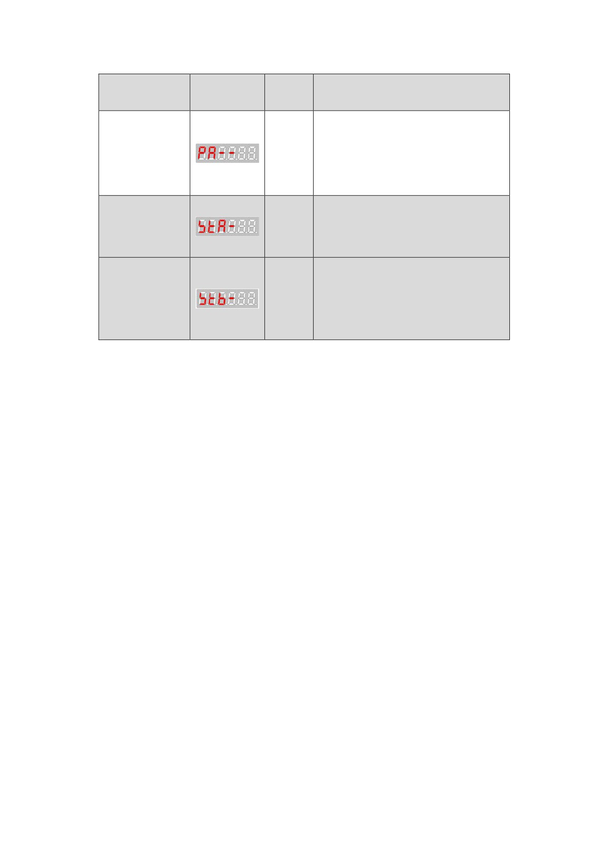
Expanding
movement
Able to set parameters related
parameter
60~75
mode
to the spindle motor
Control
Able to set spindle orientation
parameter
0~15
speed, orientation position。
mode
Expanding
control
Could choose the speed feedback
0~15
filter, spindle motor and so on.
parameter
mode
7.1.2 Parameter operation instructions
This section describes the modify and view parameters during debugging
and precautions, does not include the adjustment and adaptation of
parameters
1、Drive unit can only view the movement parameter PA, status monitoring,
auxiliary parameters and control parameters STA parameters after power
on.
2、Set PA—41to 2003, you could view or modify parameters PA and STB.
3、Any time,PA--23 、PA--24、 PA—25、PA—26 are effective only when saving
parameters and restarting power.
4、Before the drive unit running,you must modify parameter PA—59(Notice:
modify parameter PA—59 after setting PA—41 to 2003)。
If the drive unit and motor code is not in Table 7.3,you need to set
the parameters related to the motor manually,and refer to
7.2.Non-standard motor parameters
5、The drive unit performance debugging please refer to the relevant
sections of 7.2.
6、The steps of trial operation of the drive unit, please reference the
relevant sections of Chapter 8.
7.2 Movement Parameter Mode
7.2.1 Movement parameters
Series HSV-180AS spindle drive can provide 60 movement parameters.
For details about the movement parameters, see Table 7-2, and Table
7-3.
In the application control mode:
P: indicates position control (suitable for spindle position
control and spindle orientation)
S: indicates speed control.
Table 7-2 Movement parameters
Adaptive
Value
Defaul
No.
Parameter
Control
Unit
range
t value
Mode
Position control
mode
10~
0
P
200
0.1Hz
Speed proportional
1500
gain
Torque filter time
1
P,S
0~499
4
0.1ms
constant
Speed proportional
25~
2
S
350
gain 1
5000
Speed integral
5~
3
S
30
ms
time constant 1
32767
Speed feedback
4
P,S
0~9
1
filter factor
Deceleration time
5
S
1~1800
40*
0.1s/8000r/min
constant
Acceleration time
6
S
1~1800
40*
0.1s/8000r/min
constant
Speed command
10~
7
S
6000*
1r/min
input gain
12000
Speed command zero
-1023~
8
S
0
drift compensation
1023
Speed command gain
9
S
80~120
100
1%
adjusting
10
Current amplitude
P,S
10~300
200
PA-53orPA-56
limit for maximum
current ratio of
torque
the motor
(10%~300%)
Speed reached
0~
11
P,S
10
1r/min
range
32767
Test range for
1~
12
P
30
0.1r
position tolerance
32767
Speed ratio
Only applicable in
1~
13
numerator of
P
1
orientation
32767
spindle to motor
control
Speed ratio
Only applicable in
1~
14
denominator of
P
1
orientation
32767
spindle to motor
control
15
Reserved
C-axis feed
16
P
0~100
0
forward gain
Maximum speed
1000~
17
P,S
9000
1r/min
limit
25000
PA-53 or PA-56 as a
percentage of the
Overload current
motor rated
18
P,S
10~200
150
setting
current
(10%~200%)
Overload time
10~
19
setting of the
P,S
100
0.1s
30000
system
-20000
20
Internal speed
S
0
1r/min
~20000
J JOG operation
21
P,S
0~500
300
1r/min
speed
Command pulse
22
input mode
P,S
0~3
1
Select the control
mode to the
Selection of
spindle drive
23
P,S
0~3
1
z
0: the C-axis
control mode
position
control mode
that receive
position pulse
input command
z
1:
the
external speed
control mode
that receives
the
speed
analog
input
command
z
2:the external
speed control
mode
that
receives the
speed
pulse
input command
3:Internal speed
control mode, and
the internal speed
command is set by
the movement
parameter PA--20
Magnetic logarithm
24
of spindle motor
P,S
1~8
2
◆
0:1024pps
1:2048pps
2:2500pps
3:256 Sine and
cosine
incremental
Spindle motor
encoder
encoder optical
25
P,S
0~3601
0
4:EQN1325/1313
-electrical
5:Other Sine and
resolution ◆
cosine
incremental
encoder
Such as 1201 is
1200 line sine and
cosine
incremental
encoder,the bits 1
meanssine and
cosine signal
SM spindle motor
-32767
offset
26
P,S
~
0
compensation
32767
◆
Current control
25~
27
proportional gain
P,S
1000
32767
◆
Current control
1~
0.1ms
28
P,S
50
integral time ◆
32767
29
Zero-speed reached
P,S
0~300
10
1r/min
30
Speed rate
S
1~256
64
1/64
Correspond to
State control word
-32768
1
STA15-STA0
31
~
4096
32767
Correspond to
State control word
-32768
2
STB15-STB0
32
~
1
32767
PA-53 as a
percentage of the
motor rated
33
Flux current
P,S
10~80
60
current
(10%~80%)
Time constant of
34
spindle motor
P,S
1~4500
1500
0.1ms
rotor electric
Rated speed of
100~
35
P,S
1500
1r/min
spindle motor
12000
PA-33 as a
The minimum flux
percentage of flux
36
P,S
5~30
10
current
current
(5%~30%)
The range for
37
spindle
P
0~100
10
pulse
orientation
finished
Spindle
38
P
40~600
100
1r/min
orientation speed
Spindle
-32767
39
orientation
P
0
pulse
~32767
position
z
The
incremental
angle
for
indexing
orientation is
PA-40
×
360/ppr0/8
×
the
angular
ratio
for
indexing
orientation
z
If the SET-13
is set to
0,
the value
of
ppr0
is
multiplying
the
Incremental angle
resolution of
0~
40
for indexing
P
0
spindle motor
32767
orientation
optic-electri
cal encoder by
4
z
If SET-13 is
set to 1, the
value of ppr0
is multiplying
the
spindle
encoder
resolution by
4
The angular ratio
for indexing
incremental
orientation is
determined by
INC_Sel1and
INC_Sel2
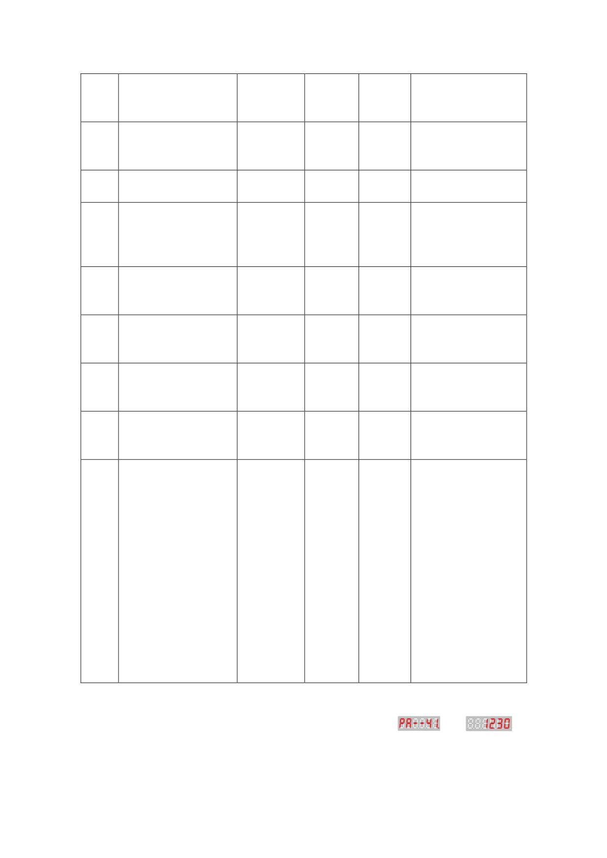
41
Reserved
0~2003
351
Display software
version
1230: Save
parameter
password
2003: View
Extended
Parameters
315:Modify the
extended
parameter
Speed proportional
25~
42
gain for position
P
450
5000
control mode
Speed integral
time constant for
5~
43
P
20
1ms
position control
32767
mode
Position
proportional gain
10~
44
for orientation
P
200
0.1Hz
1500
mode
PA-33 Ratio of
Flux current for
45
P
30~150
110
flux curren
orientation mode
(30%~150%)
Flux current for
PA-33 PA-33 Ratio
46
position control
P
30~150
110
of flux curren
mode
(30%~150%)
Spindle encoder
Spindle encoder
1~
47
P,S
4096
resolution
resolution
32767
multiplied by 4
The offset angle
48
for indexing
P,S
0~18
0
200
orientation
C-axis electronic
1~
49
gear ratio
P
1
32767
Molecular
C-axis electronic
1~
50
gear ratio
P
1
32767
Denominator
Serial
51
communication baud
P,S
0~5
2
rate
Communication
52
sub-station
P,S
1~63
1
address
IM motor rated
60~
53
P,S
188
0.1A
current
1500
IM Second speed
point corresponds
100~
Less than or equal
54
P,S
200
to the maximum load
3000
to PA—10
current
IM second load
1r/min
500~
55
current
P,S
2000
More than or equal
10000
limiting speed
to PA—35
PM spindle motor
100~
56
P,S
420
0.1A
rated current
3000
PM spindle motor
100~
57
rated rotation
P,S
2000
1r/min
5000
speed
PM Weak magnetism
1r/min
100~
58
adjusting
P,S
2500
More than or equal
10000
coefficient
PA—57
Hundred digit
means drive unit
Model:
0:35A
1:50A
2:75A
Drive unit and code
3:100A
59
P,S
0~799
202
of motor type◆
4:150A
5:200A
6:300A
7:450A
Ten and bit digit
mean motor code
(see figure 7.3)
Note:
If changing parameter, you should firstly set
as
,
otherwise it’s invalid.
Table 7-2 Movement parameters
Motor
Rated
Rated
Rated
Type
Motor
Electric
Adapter drive
PA-59
Power
Torque
Code
current
unit
Type
parameters
(KW)
(Nm)
(A)
00
GM7101-4SB61
3.7
23.6
10
HSV-180AS-035
0
HSV-180AS-035
1
01
GM7103-4SB61
5.5
35
13
HSV-180AS-050
101
HSV-180AS-050
102
02
GM7105-4SB61
7.5
47.8
18.8
HSV-180AS-075
202
HSV-180AS-075
203
03
GM7109-4SB61
11
70
25
HSV-180AS-100
303
HSV-180AS-100
304
04
GM7133-4SB61
15
95.5
34
HSV-180AS-150
404
05
GM7135-4SB61
18.5
117.8
42
405
HSV-180AS-150
06
GM7137-4SB61
22
140.1
57
406
7.2.2 Parameters Related to Asynchronous Servo Motors
Description of the parameter setting:
Parameters related to spindle motors are effective under all control
modes. HSV-180AS spindle drive adopts the indirect magnetic field
orientation control mode which achieves the control for asynchronous
motor. The key to the magnetic field orientation is the observation
for flux, in other words, it is the calculation of slip angle frequency
which is closely related to the motor parameter. Therefore, setting
parameter correctly is the first and foremost.
PA--17
Default
NO.
Parameter
Scope
Unit
value
PA--17
Maximum speed limit
1000~25000
9000
1r/min
Function and setting:
① According to motor type set maximum speed of the spindle
motor。
② Regardless of the direction of rotation.
PA--24
Default
NO.
Parameter
Scope
Unit
value
PA--24
Magnetic logarithm of
1~8
2
spindle motor
Function and setting:
① According to motor type set maximum speed of the spindle
motor。
PA--25
Default
NO.
Parameter
Scope
Unit
value
PA--25
Spindle motor encoder
0~3601
0
optical -electrical
resolution
Function and setting:
① PA--25must be filled in based on the technical data of the motor.
② Setting parameters:
0:1024pps
1:2048pps
2:2500pps
3:256 Sine and cosine incremental encoder
4:EQN1325/1313
5:Other Sine and cosine incremental encoder
Such as 1201 is 1200 line sine and cosine incremental
encoder,the bits 1 meanssine and cosine signal
PA--33
Default
NO.
Parameter
Scope
Unit
value
PA--33
IM Flux current
10~80
60
1%
Function and setting:
1. PA--33 is the no-load current of the rated speed.
z For the 2.2KW to 11KW spindle motor, the no-load current is
40% to 60% of the rated current.
z
For the 15KW to 22KW spindle motor, the no-load current is
30% to 40% of the rated current.
z If PA-33(flux current) is set too large, it will cause
saturation flux which could result in motor oscillation, and
a larger fluctuation in rotary speed.
z If the value of excitation current is set too small, it will
cause insufficiency of magnetic flux stimulation which will
lead to a great drop of motor output torque loop.
PA--34
Default
NO.
Parameter
Scope
Unit
value
IM Time constant of
PA--34
spindle motor rotor
1~4500
1500
0.1ms
electric
Function and setting:
2. The value of PA-34 (time constant of spindle motor rotor electric)
can be specified based on the rotor inductance of the motor
(self-inductance + leakage inductance) and rotor resistance.
z For the 2.2KW to 11KW spindle motor, the time constant is from
1300 to 1800.
z For the 15KW to 30KW spindle motor, the time constant is from
3000 to 4000.
z If PA-34 is set too large or too small, it will cause a greater
deviation of the magnetic field oriented angle, which may cause
a great drop of motor output torque loop.
PA--35
Default
NO.
Parameter
Scope
Unit
value
IM Rated speed of
PA--35
100~12000
1500
1r/min
spindle motor
Function and setting:
① PA--35must be filled in based on the technical data of the motor.
PA--36
Default
NO.
Parameter
Scope
Unit
value
IM The minimum flux
PA--36
5~30
10
1%
current
Function and setting:
PA-36 (minimum flux current limit) is set for preventing the
insufficiency of magnetic flux stimulation when the motor running at a
high-speed. Generally PA-36 is set to 0.1 times of the value of PA-33 (flux
current) or smaller.
PA--53
Default
NO.
Parameter
Scope
Unit
value
PA--53
IM Motor rated current
60~1500
188
0.1A
Function and setting:
According to motor type set rated current of the spindle motor.After
setting(PA--59), this parameter will be automatically set.
7.2.3 Parameters Related to Movement Control
Table 7-10 Parameters related to movement control
Value
NO.
Parameter
Function
Range
1. Set the parameters to the
Position
proportional gain of the position loop
10 to
control mode
regulator under the position control
9999
Speed
mode
0
unit:
proportional
2. The greater of the parameter value,
0.01
gain
the greater of the gain and the
1/S
rigidity, and the smaller of the
position lag value at the same