Series HSV-180AS AC Spindle Drive. User Manual (V1.00 2012.4) - page 2
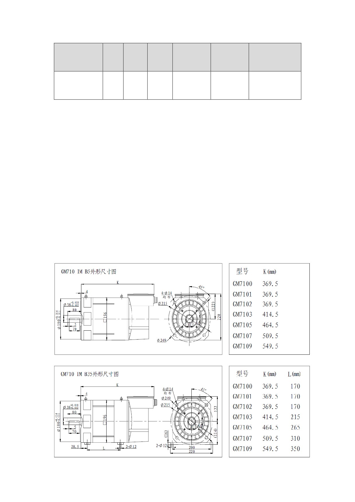
5000
HSV-180AS-30
GM7185-4SB6
51
325
120
1500
0
1
/1.4
5000
HSV-180AS-45
GM7189-4SB6
75
478
165
1500
0
1
/1.4
Note:
It is special mentioned that if configured with encoder made in China
or Japan, the maximum rotary speed is 6000r/min; if configured with
encoder made in Germany, the maximum rotary speed is 15000r/min.
3.2.6 Installation Dimension of the Motor
The following figure shows the installation dimension of the series
GM7AC servo spindle motor.
Figure 3-10 Installation dimension of series GM7 AC servo spindle
motor
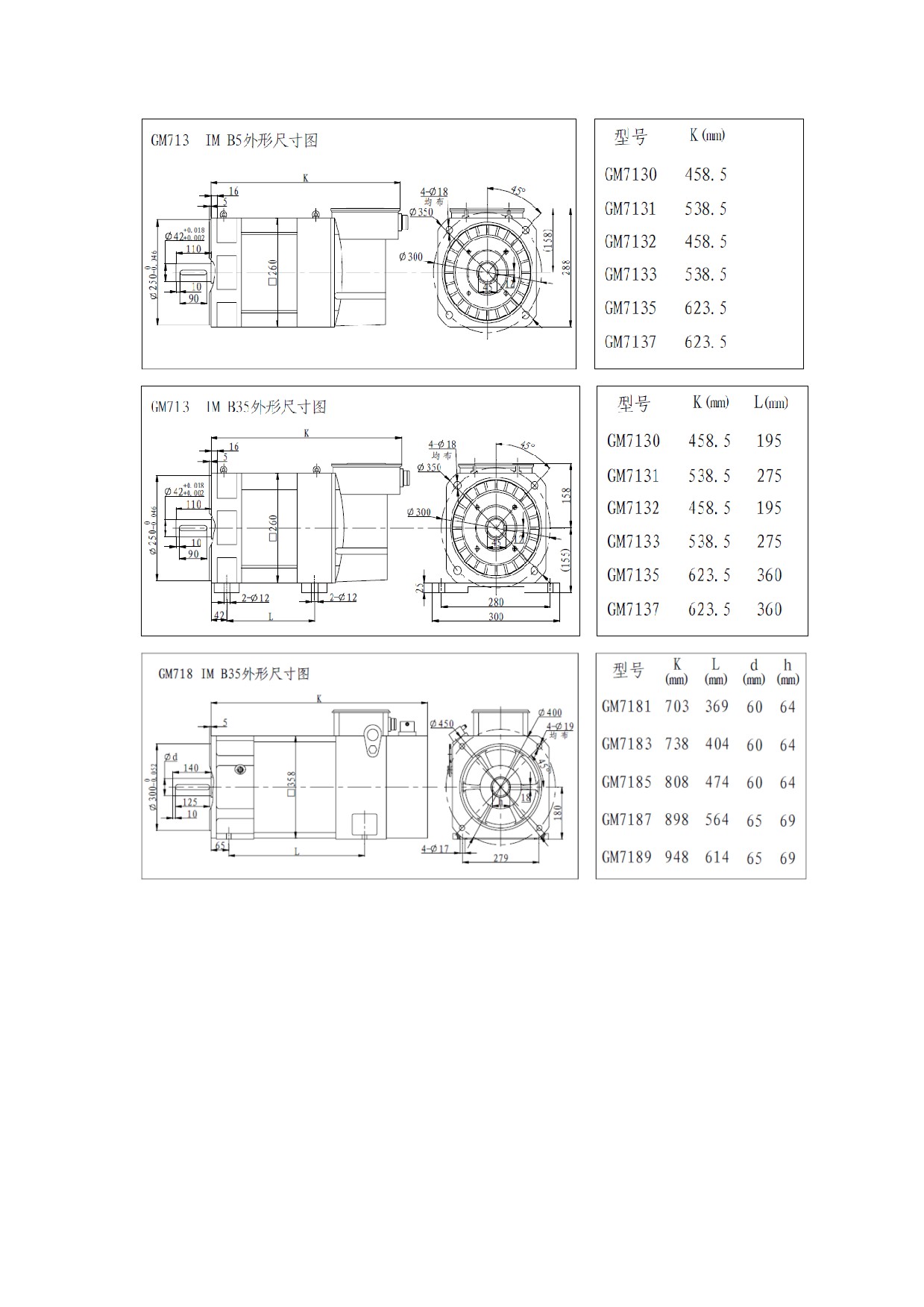
NOTE:After GM710、GM713 assembling well, total length is K+61
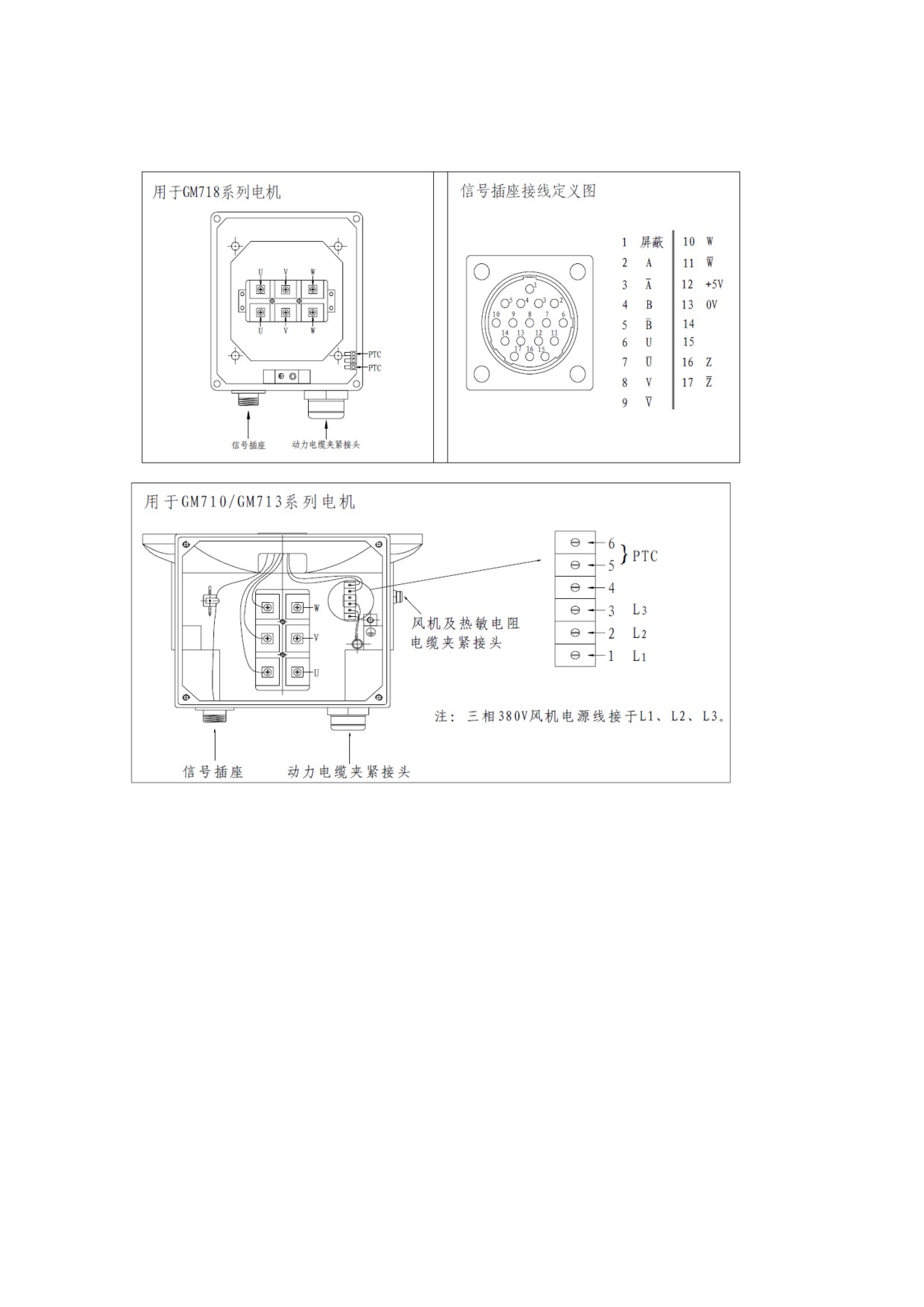
3.2.7 Connect terminal definition
Figure 3-11 Connect terminal of series GM7 AC servo spindle motor

4 Installation
4.1 Products Check
After receiving products, users must check the items as the following
table.
Item
Reference
Whether the product
Check the product appearance to make sure that
is damaged
the product is not damaged during transportation.
Whether the product
Check and make sure the type of the spindle drive
type is in accordance
unit and motor is in accordance with that in order
with that in order
Whether
the
Check the packing list and make sure that the
accessories
are
accessory type and quantity is correct.
complete
Whether the motor
Check and make sure that the motor shaft can be
shaft can be easily
easily turned by hand, except motors with brakes.
turned by hand
If there are any problems, contact directly with the applier or our
company.
Warning
● Do not install spindle drive which are damaged or with
incomplete parts.
● The spindle drive units must be matched with the
compatible spindle motor.
● Do not touch the spindle motor shaft directly, which can
cause corrosive.
4.2 Installation Environment
4.2.1 Environment Temperature
The working environment temperature is between 0℃ to 40℃. If the
temperature over 40℃, de-rating required.
4.2.2 Humidity
Air relative humidity is equal or less than 90%. No condensation.
4.2.3 Altitude
Spindle drive units must be installed below 1000m altitude. If over
1000m altitude, de-rating required.
4.2.4 Vibration and Impulsion
Spindle drive is not load bearing and anti-collision. When installing
and working, it must be free from oscillation and impact, and take
measures to control the oscillation below 0.5G(4.9m/S2).
4.2.5 Water
Spindle drive cannot be installed in the water spray or condensation
location.
4.2.6 Air Pollution
The spindle drive must be free from air pollution. It must be installed
in the electric cabinet which is resistant to corrosive and flammable
gas, as well as prevent conductive object, mental dust, oil mist and
liquid from entering to the interior of the equipment.
4.3 Installation of Spindle Drive
Warning
z The spindle drive must be installed in the electric cabinet
with fine protective function.
z The spindle drive must be installed in accordance with the
specified direction and interval to ensure enough cooling.
z The spindle drive cannot be installed near combustibles that
may cause fire hazard.
4.3.1 Installation Methods of HSV-180AS-035,050,075
1. Installation Methods
There are three types of wall installation: directly installed
without auxiliary devices, with auxiliary devices, and external heat
sink installation. For their installation diagrams, see Figure 4-1,
Figure 4-2, and Figure 4-3. You can use any of the three methods, and
install the servo drive vertically。
2. Installation Interval
For the installation interval of single spindle drive, see Figure 4-4
and Figure 4-5.
For the installation interval of multiple spindle drive, see Figure
4-6.
During installation, leave enough intervals as possible to ensure a
good heat emission.
3. Cooling
In the electric cabinet, there must be air blew through the radiator
to prevent the ambient temperature of the spindle drive from
overheating.
Figure 4-1 Wall installation diagram of HSV-180AS-035,050,075
spindle drive (without auxiliary devices)
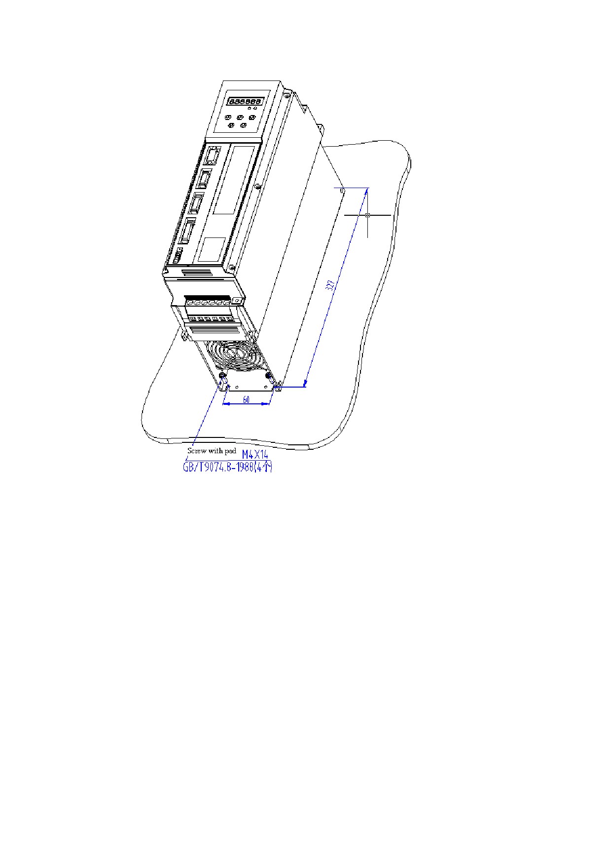
Figure 4-2 Wall installation diagram of HSV-180AS-035, 050, 075 spindle
drive (with auxiliary devices)
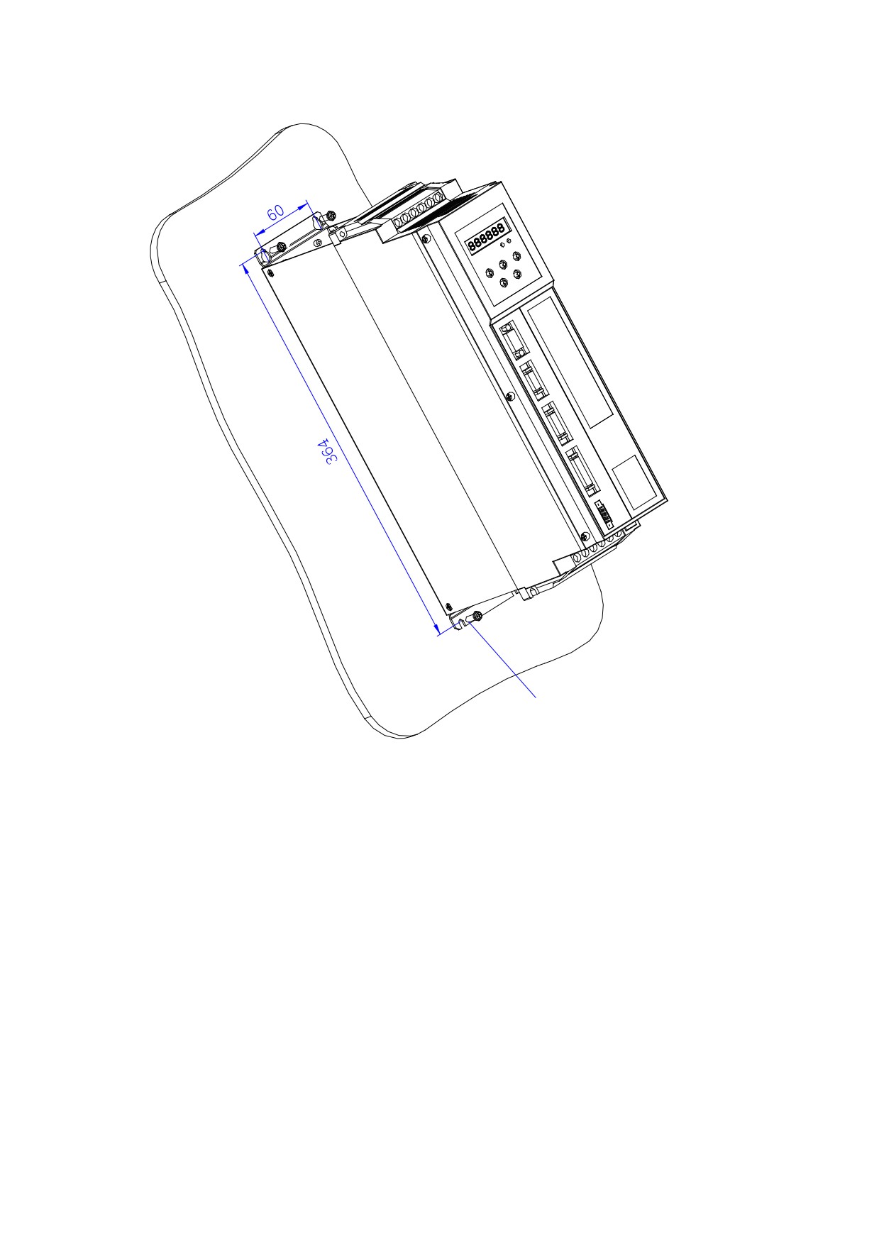
带垫组合螺钉 M4X14
GB/T9074.8-1988(4个)
Figure 4-3 Wall installation diagram for external heat sink of HSV-180AS-
035, 050, 075 spindle drive
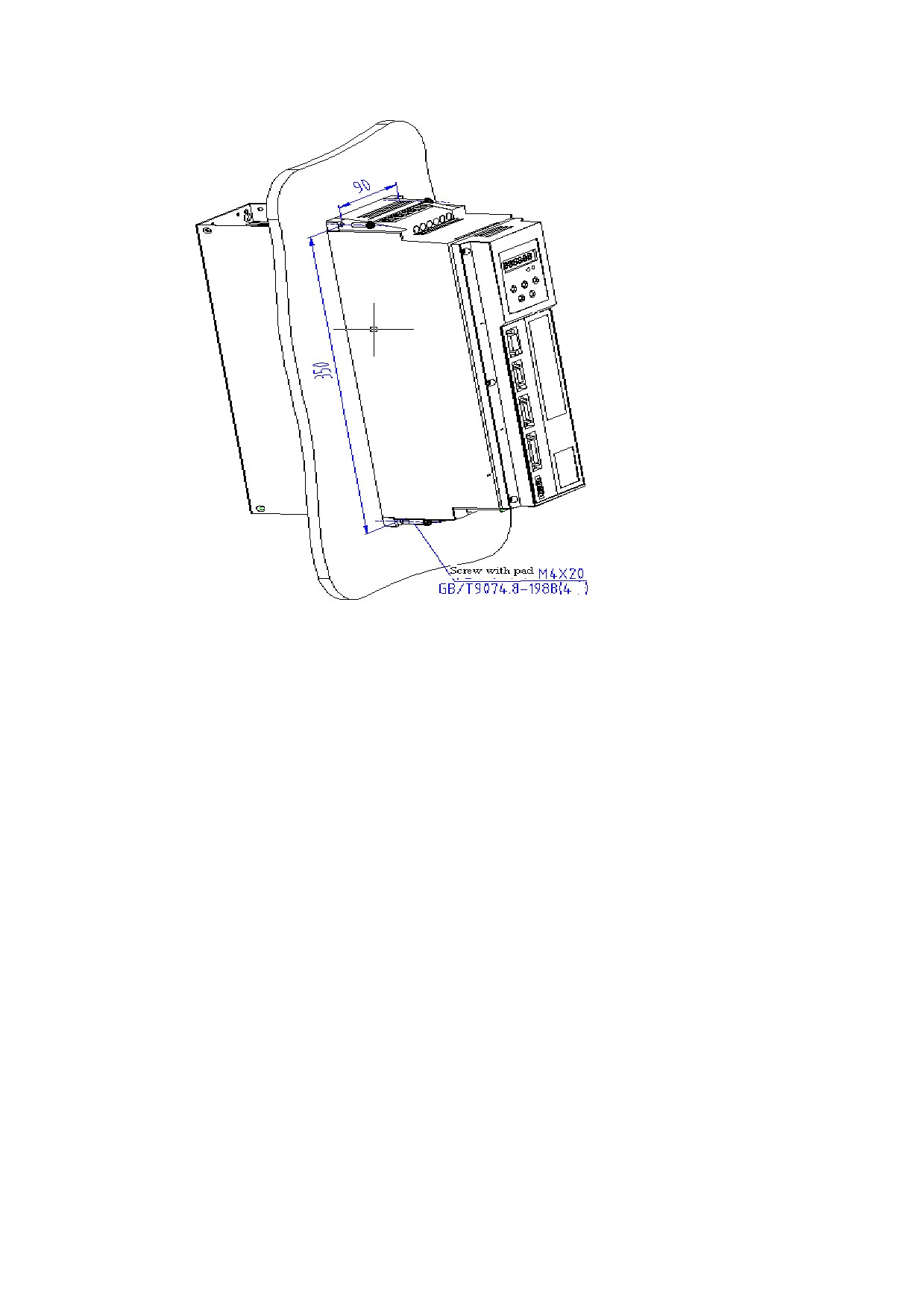
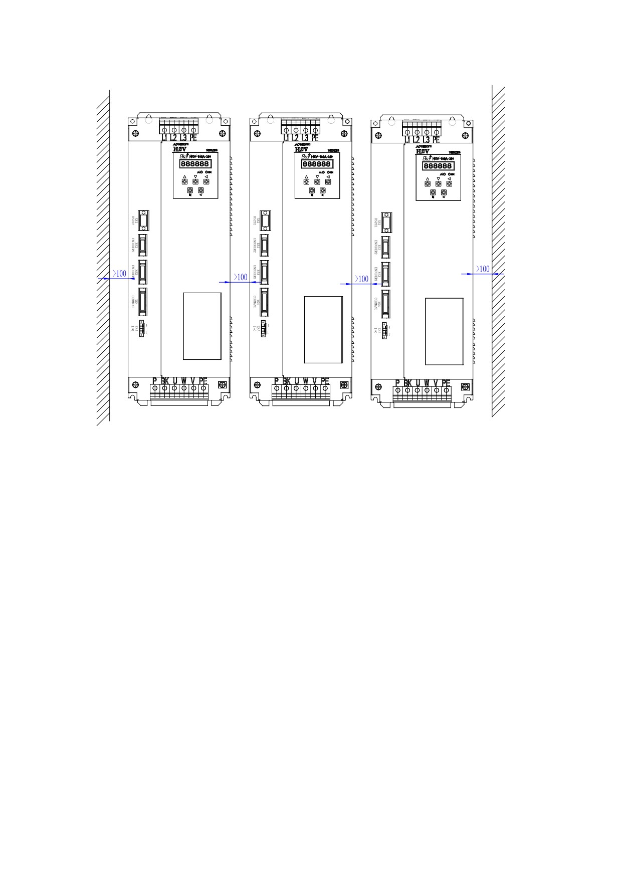
Figure 4-4 Installation interval of HSV-180AS- 035, 050, 075 spindle drive
(Wall installation)
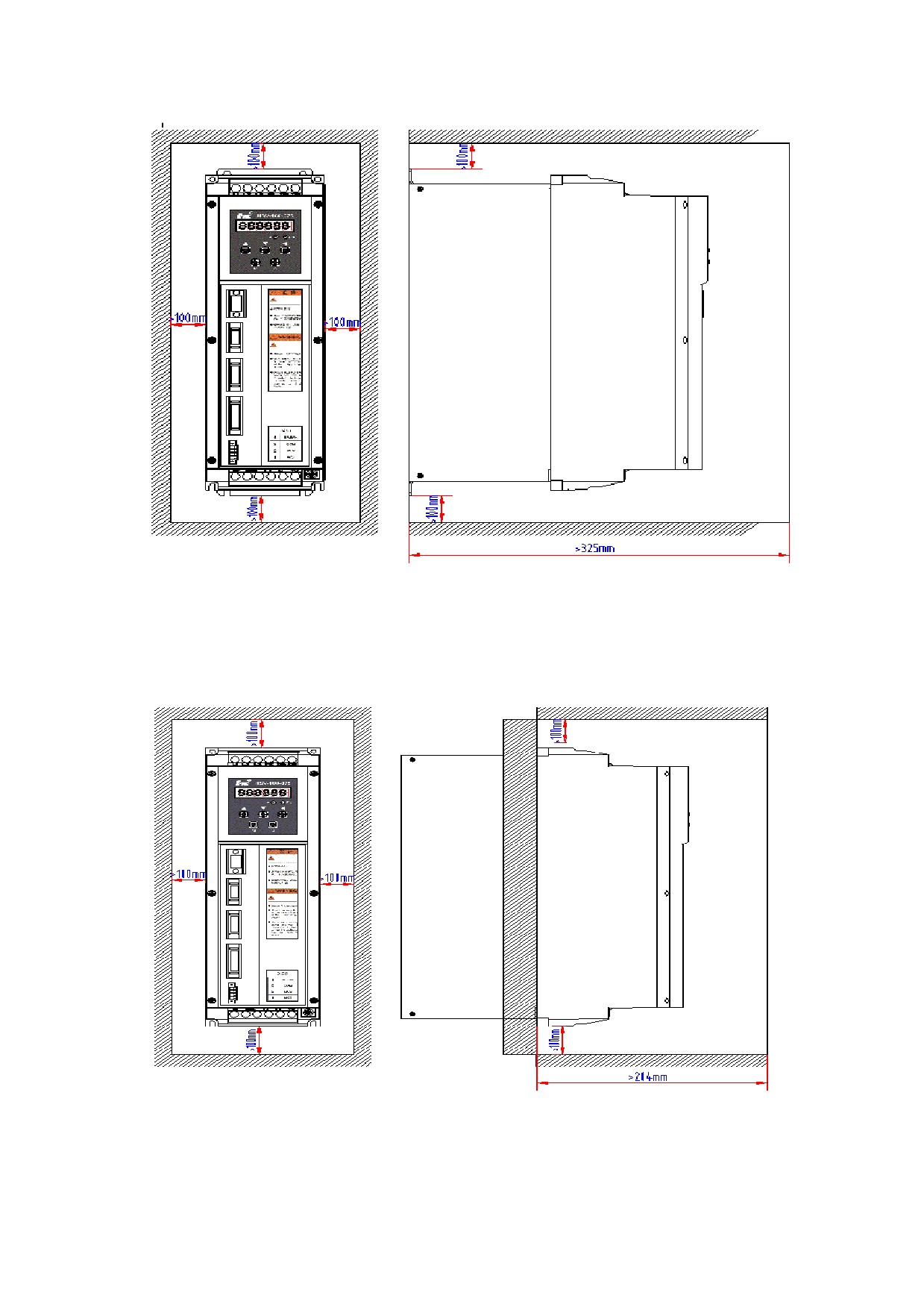
Figure 4-5 Installation interval of HSV-180AS- 035, 050, 075 single
spindle drive
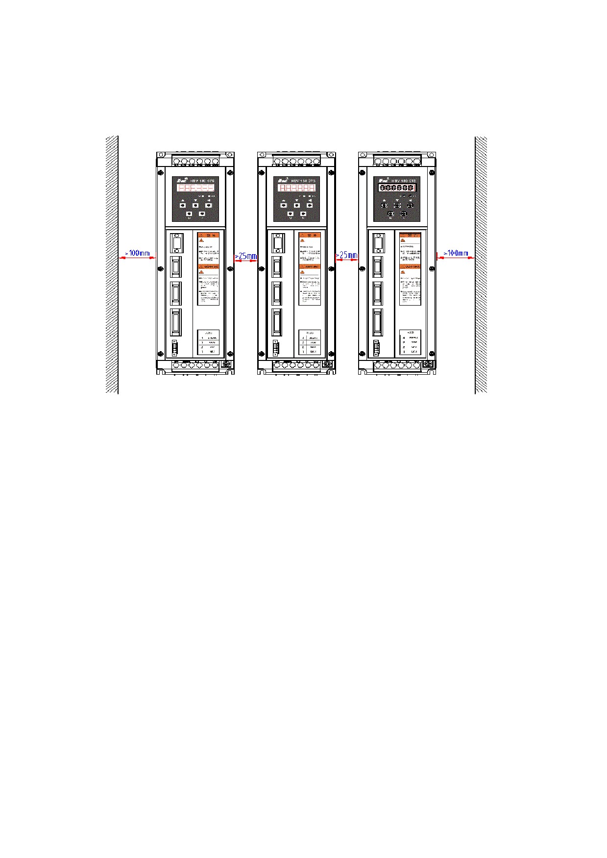
Figure 4-6 Installation intervals of HSV-180AS-035,050,075 multiple
spindle drives
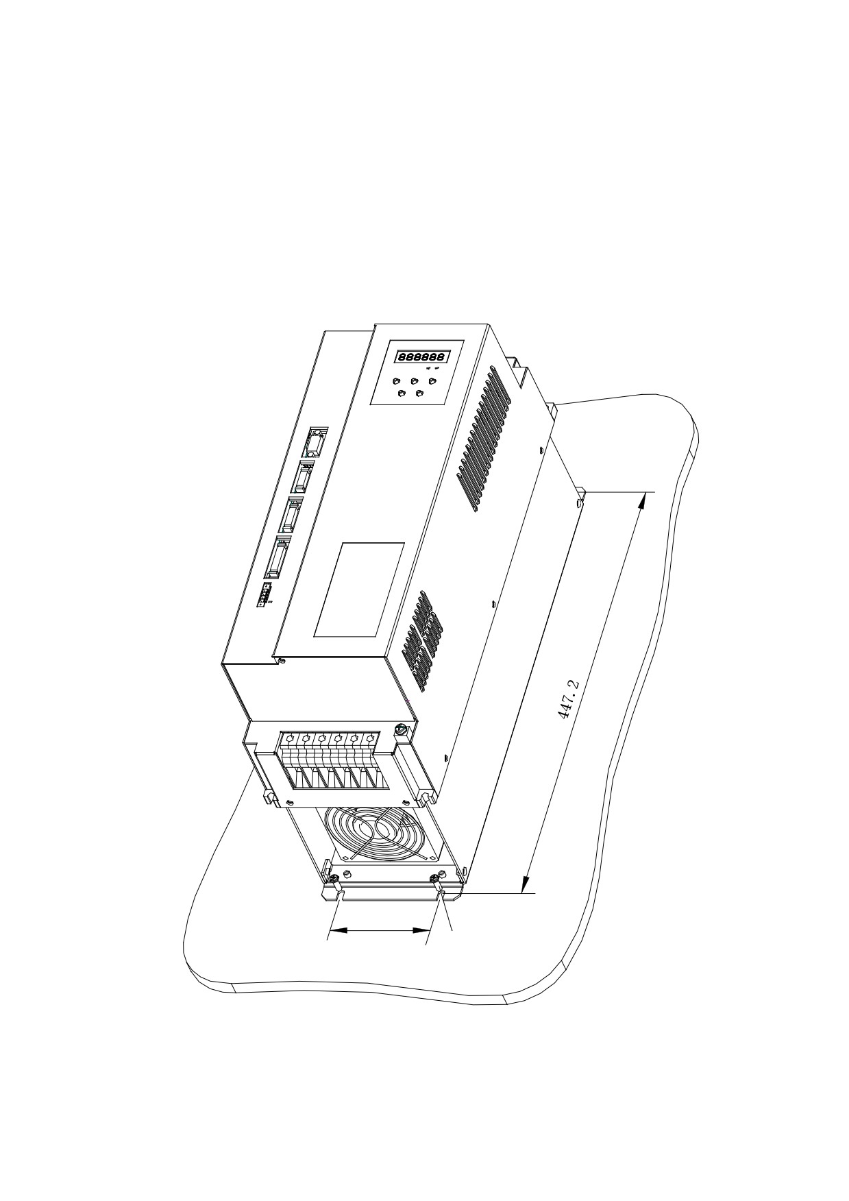
4.3.2 Installation Methods of HSV-180AS-100,150
1. Installation Methods
There are two types of wall installation: directly installed with
auxiliary devices, and external heat sink installation. For their
installation diagrams, see Figure 4-7, Figure 4-8.You can use any of
the three methods, and install the servo drive vertically。
2. Installation Interval
For the installation interval of single spindle drive, see Figure 4-9
and Figure 4-10
For the installation interval of multiple spindle drive, see Figure
4-11
During installation, leave enough intervals as possible to ensure a
good heat emission.
3. Cooling
In the electric cabinet, there must be air blew through the radiator
to prevent the ambient temperature of the spindle drive from
overheating.
Figure 4-7 Wall installation diagram of HSV-180AS-100,150 spindle
drive (with auxiliary devices)
95
4-M5×16螺钉安装
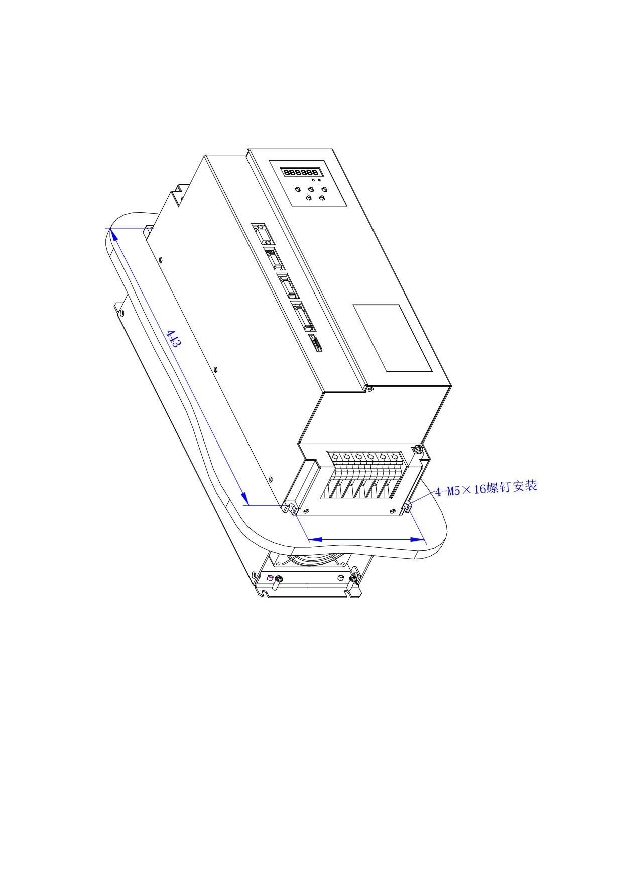
Figure 4-8 Wall installation diagram for external heat sink of HSV-180AS-
100, 150spindle drive
146
Figure 4-10 Installation interval of HSV-180AS- 100,150 single spindle
drive
(wall station)
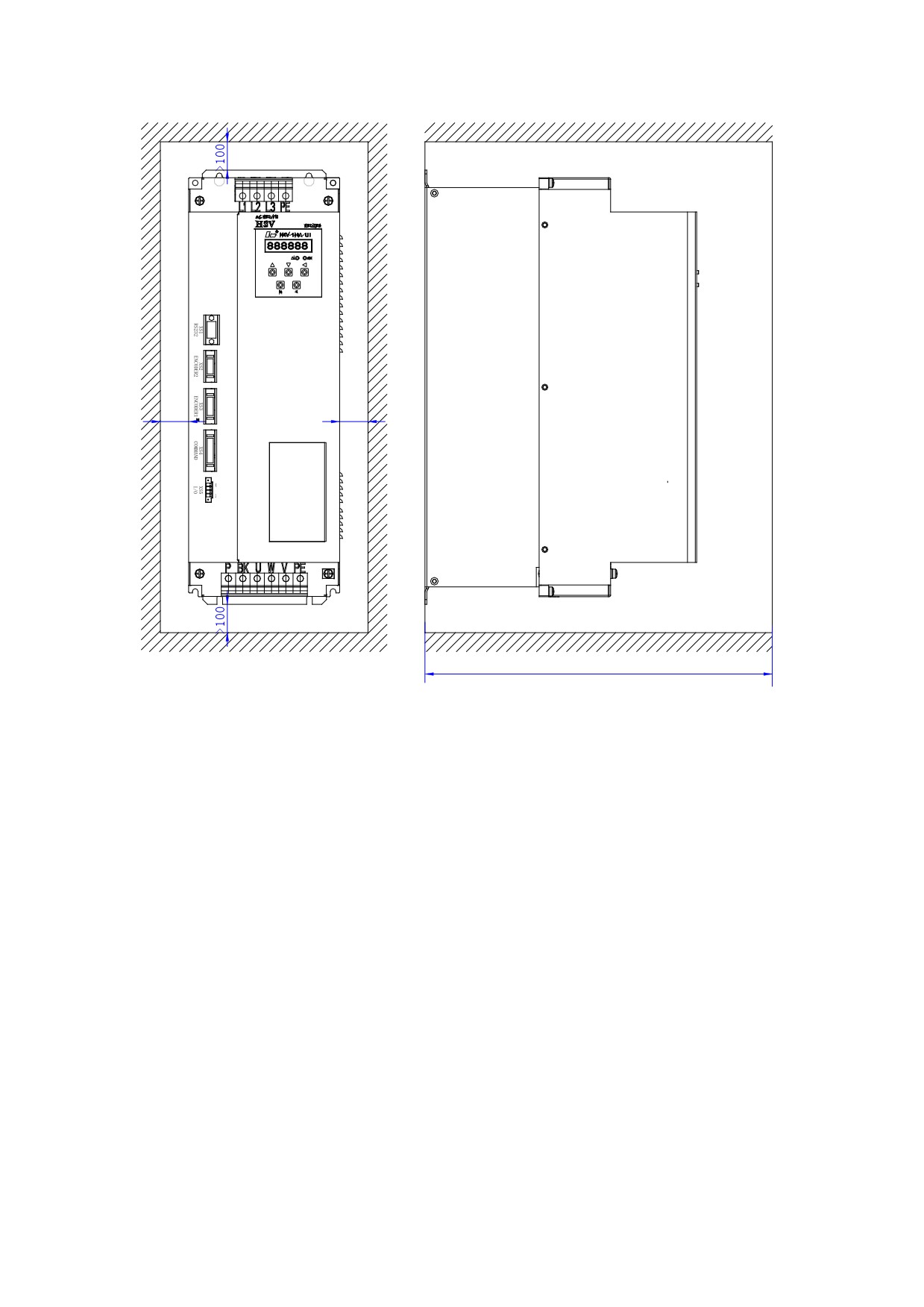
>100
>100
>370mm
Figure 4-11 Installation interval of HSV-180AS- 100,150 single spindle
drive
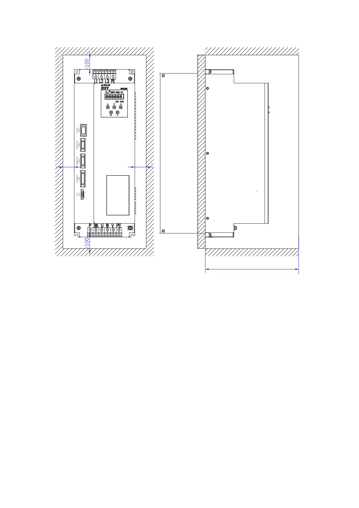
>100
>100
>250mm
Figure 4-11 Installation interval of HSV-180AS- 100,150 multiple spindle
drive
4.3.3Instllation method of HSV-180AS-200,300,450
1. Installation Methods
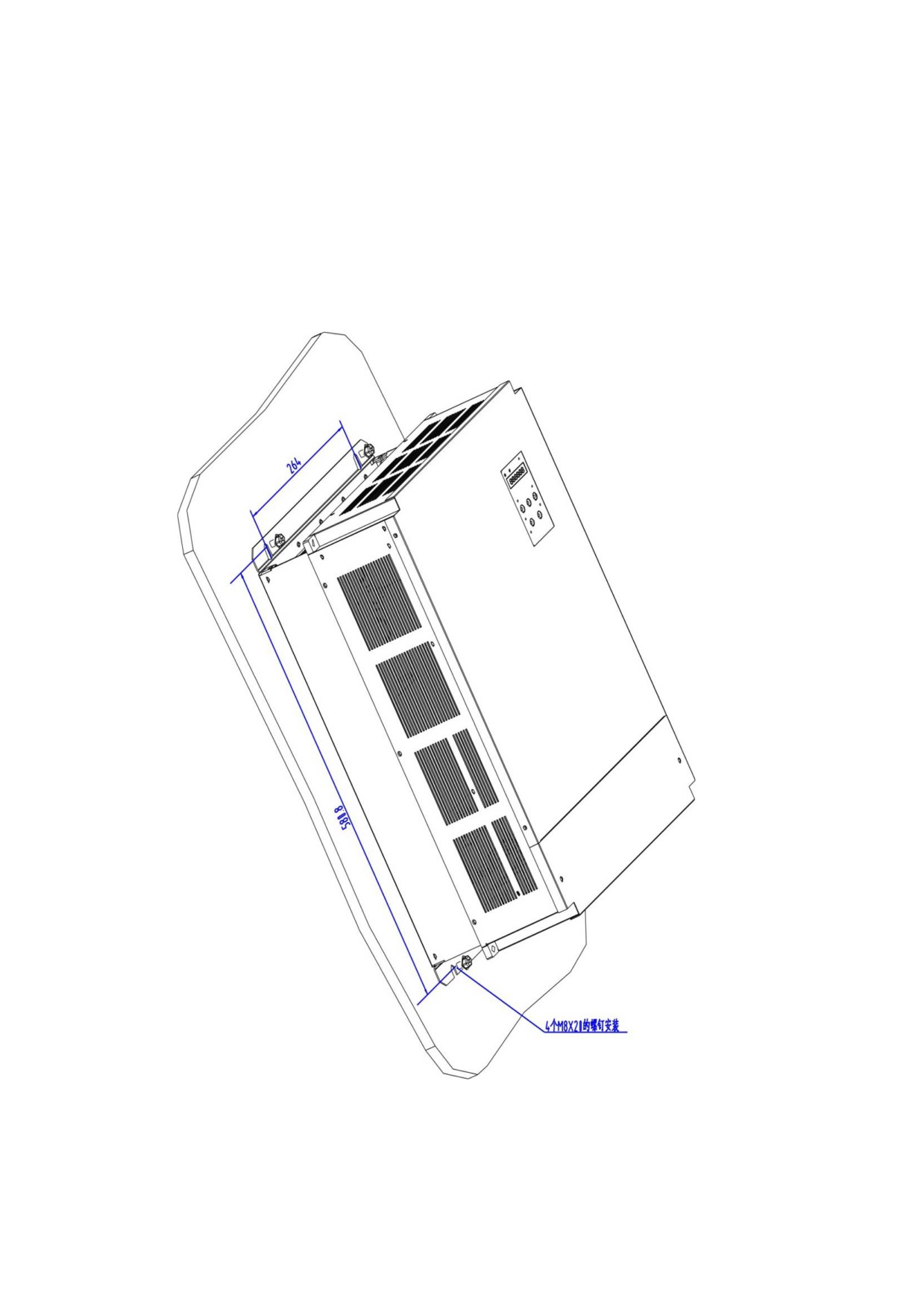
There are two types of wall installation: directly installed with
auxiliary devices, and external heat sink installation. For their
installation diagrams, see Figure 4-12, Figure 4-13.You can use any
of the three methods, and install the servo drive vertically。
2. Installation Interval
For the installation interval of single spindle drive, see Figure 4-14
and Figure 4-15
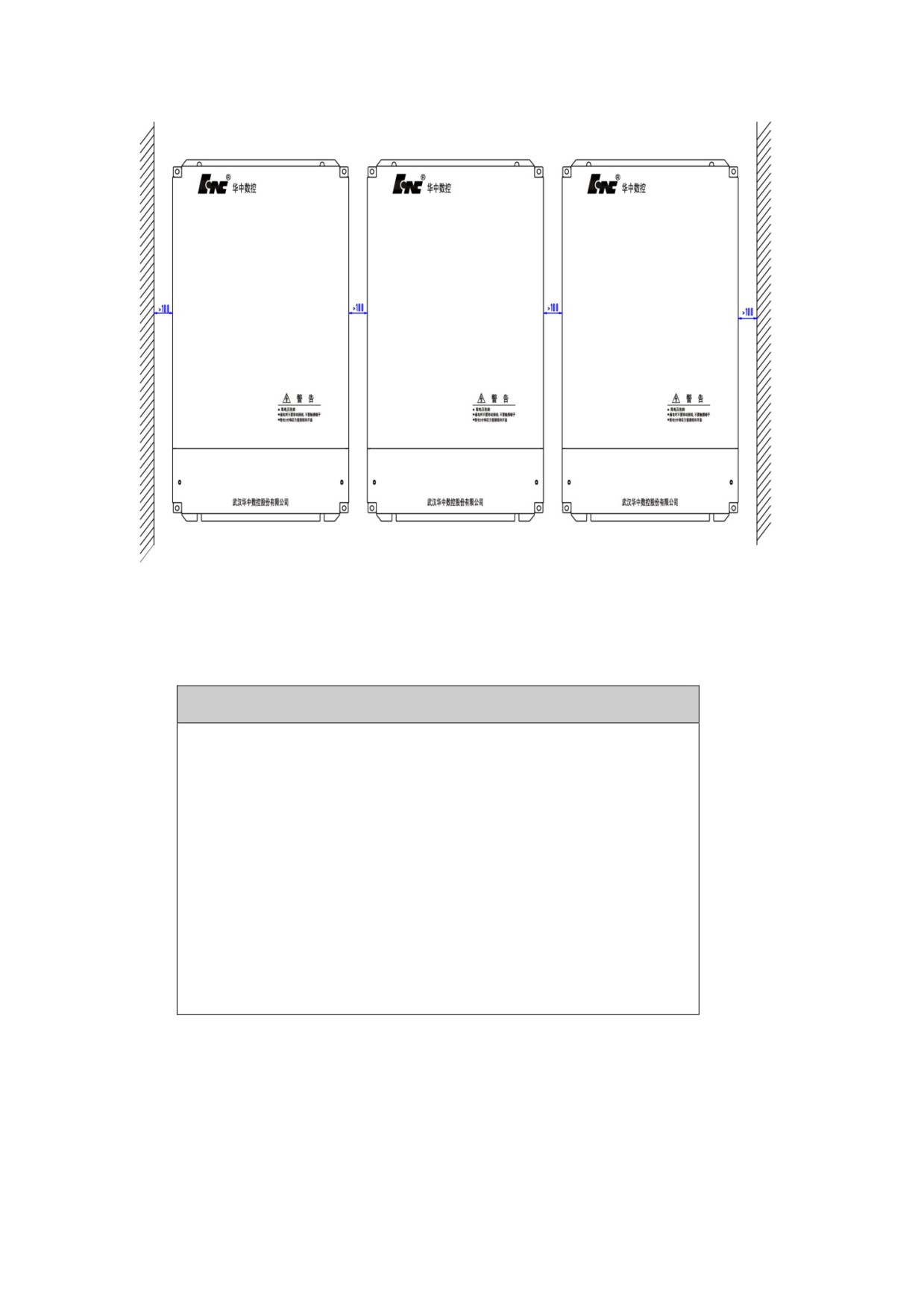
For the installation interval of multiple spindle drive, see Figure
4-16
During installation, leave enough intervals as possible to ensure a
good heat emission.
3. Cooling
In the electric cabinet, there must be air blew through the radiator
to prevent the ambient temperature of the spindle drive from
overheating.
Figure 4-12 Wall installation diagram of HSV-180AS-200,300,450
spindle drive (with auxiliary devices)
Figure 4-13 Wall installation diagram for external heat sink of HSV-180AS-
200, 300,450 spindle drive
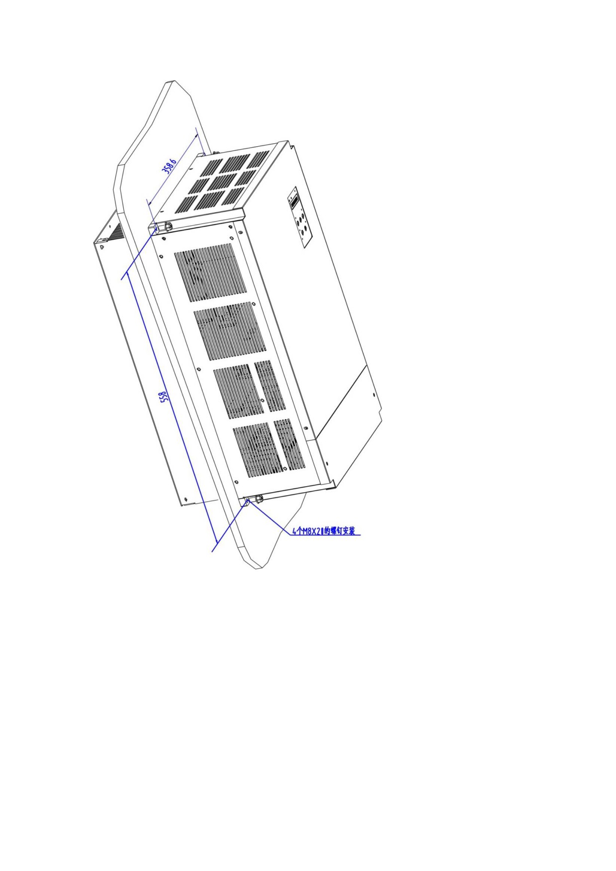
Figure 4-14 Installation interval of HSV-180AS- 200,300,450 single
spindle drive
(wall station)
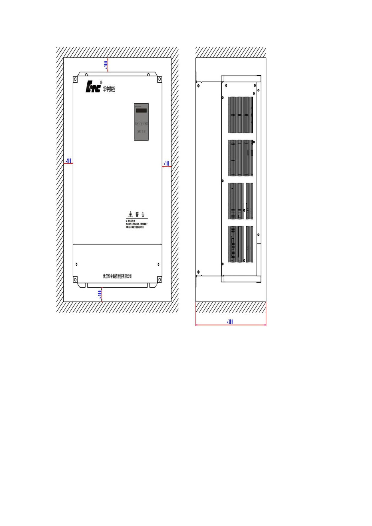
Figure 4-15 Installation interval of HSV-180AS- 200,300,450 single
spindle drive
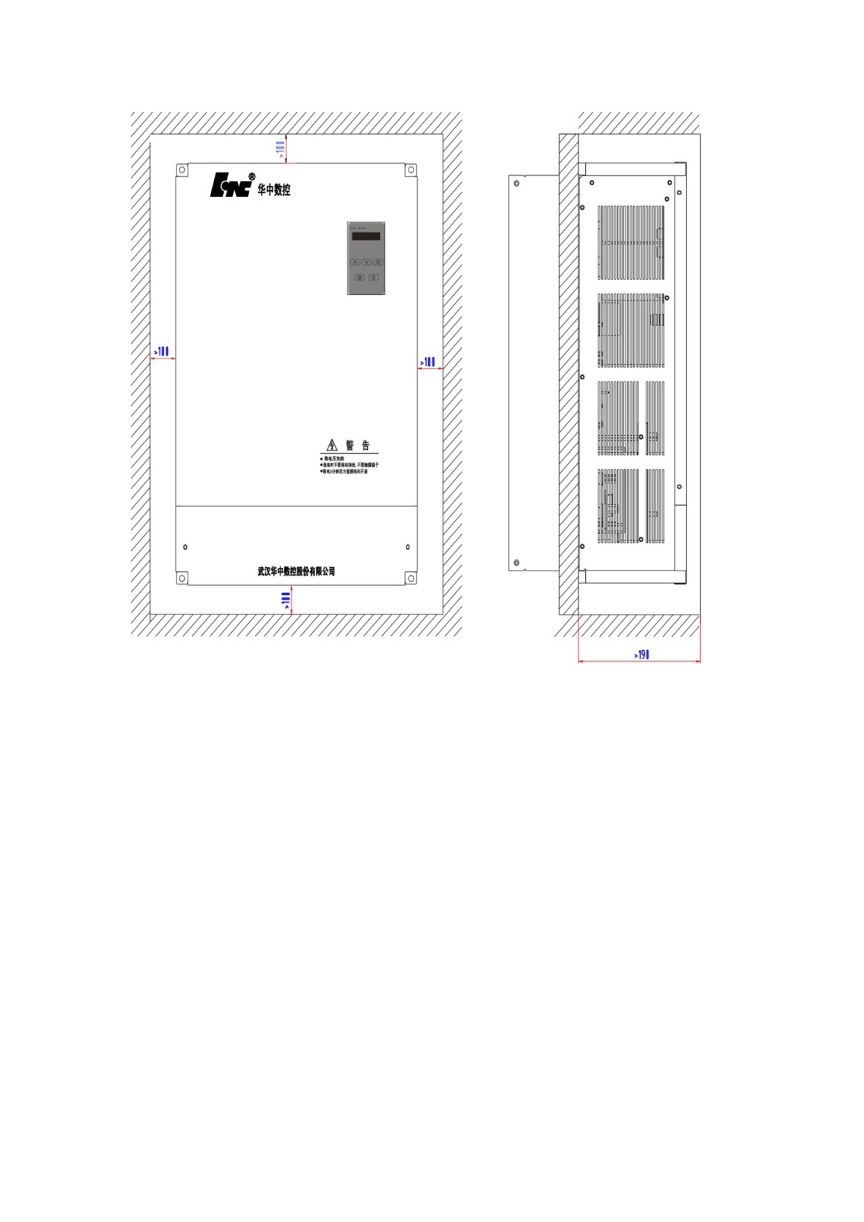
Figure 4-16 Installation interval of HSV-180AS- 200,300,450 multiple
spindle drive
4.4 Installation of Spindle Motor
Warning
z Do not knock the motor or encoder so as to prevent the
motor from oscillation or impact.
z When carrying the motor, do not drag the motor shaft,
leading-out wire or encoder.
z Do not overload motor shaft, otherwise the motor may
be damaged.
z The motor must be firmly installed and prevent
loosening.
4.4.1 Installation Environment
1. Prevention
The spindle motor is not water-proof. When installing and operating,
the motor must be guard against liquid spilling and prevent oil mist
from entering the motor through motor leads and motor shaft. If users
need water-proof motor, make it clear when ordering.
2. Temperature and Humidity
The environmental temperature must be between 0 degree Celsius and
40 degree Celsius. Humidity cannot greater than 90% RH and there is
no condensation. After long-time operation, the motor will heat up.
It is recommended that you use forced cooling or use derating motors
if there is less space or the motor is closed to heating equipments
3. Oscillation
The motor must be free from oscillation, and take measures to control
the oscillation below 0.5 G(4.9m/S2).
4.4.2 Installation Method
1. Installation Method
The GM7 series can be installed vertically and horizontally.
2. Installation Notes
During installing and removing pulley, do not knock the motor or
motor shaft to prevent damaging the encoder. Use the spiral
drawing tools to install and remove the thermal expansion
expansion-type coupling.
Series GM7 motor cannot withstand the larger axial load and radial
load. It is recommended that you use the flexible coupling to
connect the load.
When fixing the motor, use spring washer to tighten the bolts to
prevent loosening

5 Wiring
Warning
z Wiring and wiring inspection personnel must have required
capabilities.
● Wiring and wiring inspection personnel must wait 5 minutes
after power off for all wiring or wiring check to prevent
from electronic shock.
Caution
● Must be wiring in accordance with the terminal voltage and
the polarity to prevent from equipment damage or personal
injury.
● Spindle drive unit and spindle motor must be reliably
grounded.
z Do not directly hammer at the motor shaft when connect or
disconnect its mechanic part to protect encoder from being
damaged.
● Try to align the motor shaft to the optimum level to prevent
from oscillation or bearing damage.
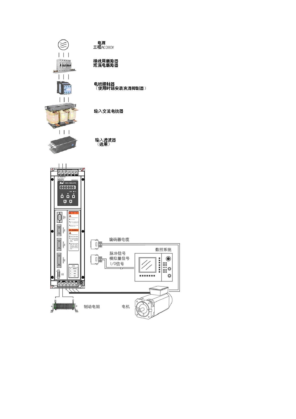
5.1 connectors
Figure 5-1 shows the interface configuration of HSV-180AS
5.2 Terminal Configuration
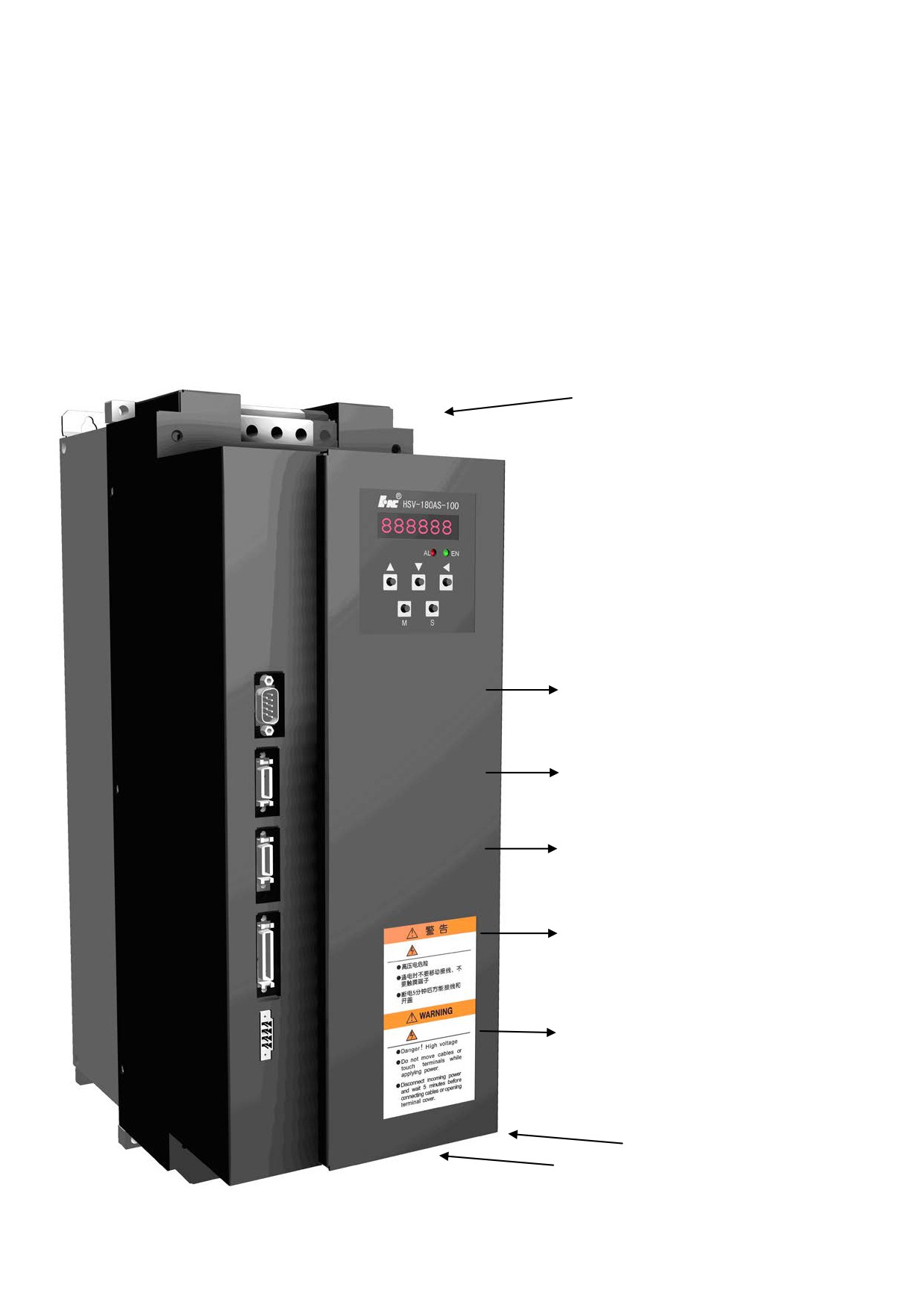
Figure 5-2 shows the interface configuration of HSV-180AS. In the
figure, XT1 and XT2 are the terminal blocks; XS1 is a DB9 socket; XS2,
XS3, and XS4 are high-density sockets; XS5 is a wiring terminal.
Figure 5-2 Interface configuration of HSV-180AS
XT1 电源输入端子
XS1 RS232
通信接口
XS2 ENCODER2
主轴编码器输入接
XS3 ENCODER1
主轴电机编码器输入
接
XS4 COMMAND
指令输入/输出接
XS5 I/O 输入/输出
端子
XT2 强电输出端子
5.3 Terminal Configuration
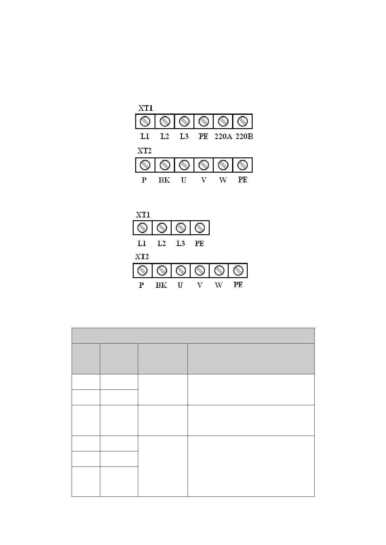
5.3.1 Terminals of HSV-180AS-035,050,075,100,150
Figure 5-3 Soldering terminal of HSV-180AS-035,050,075
Figure 5-4 Soldering terminal of HSV-180AS-100,150
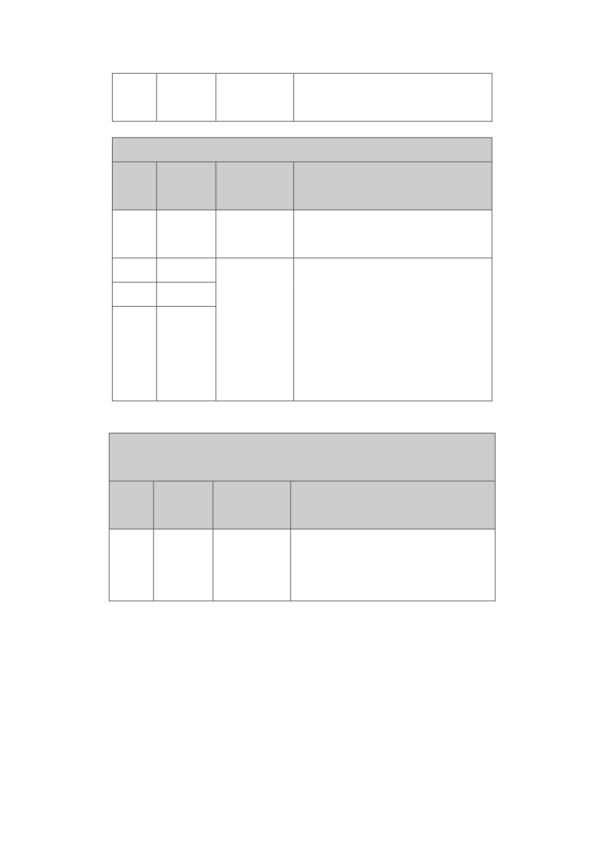
Gram5.1 XT1 power input terminal of HSV-180AS-035,050,075
XT1 power input terminal of HSV-180AS-035,050,075
Termina
NO.
Signal
Function
l Symbol
1
220B
Reserved
2
220A
Ground
Ground terminal, and the ground
3
PE
terminal
resistance is less than 4Ω
4
L3
Three-phra
Main circuit power supply input
5
L2
se main
terminal
circuit
Three phrase AC380V/ 50Hz
6
L1
power input
Note:
terminal
Do not connect to the output
terminal U, V, W.
Gram5.2 XT1 power input terminal of HSV-180AS-100,150
XT1 power input terminal of HSV-180AS-100,150
Termina
NO.
Signal
Function
l Symbol
Ground
Ground terminal, and the ground
1
PE
terminal
resistance is less than 4Ω
2
L3
Main circuit power supply input
Three-phra
3
L2
terminal
se main
Three phrase AC380V/ 50Hz
circuit
Note:
4
L1
power input
Do not connect to the output
terminal
terminal U, V, W.
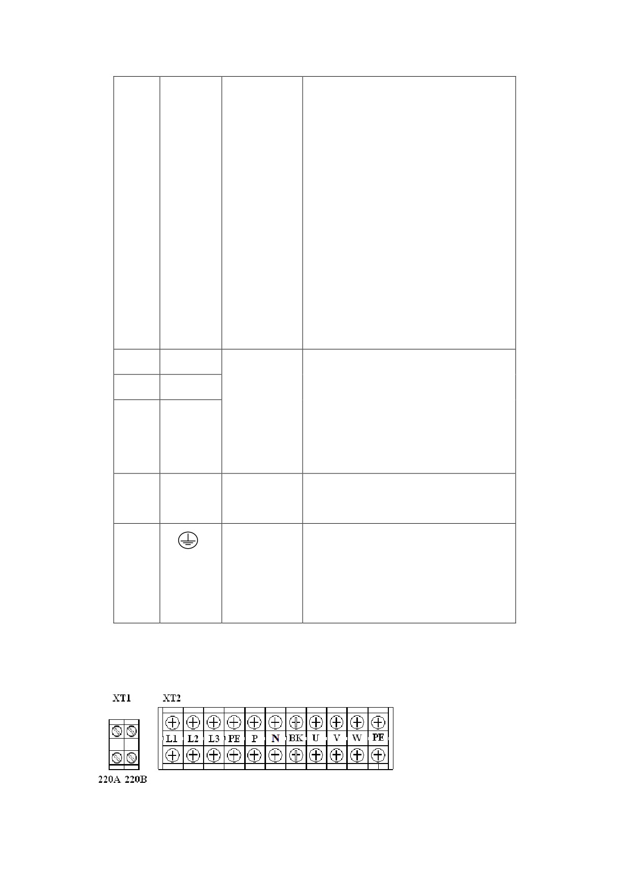
Gram 5.3 Heavy Current Output Terminal ofHSV-180AS-035,050,075,100,150
HSV-180AS-035,050,075,100,150 XT2 heavy current output
terminal
Termina
NO.
Signal
Function
l Symbol
Connection
z Build-in 70Ω/500W braking
1
P
terminal
resistors.
for
z If only use the braking
external
resistor, the terminal P and
braking
BK must be disconnected to
resistor
avoid short-circuit.
z
If an external braking
resistor is used, terminal P
2
BK
and BK must be connected to an
external braking resistor.
Note:
Terminal P and BK cannot be
shorted. Otherwise, the spindle
drive may be damaged.
3
U
Three-phra
4
V
se output
It must be linked to the motor U,
terminal of
V, and W terminals
5
W
the spindle
correspondingly.
drive
Ground
Ground terminal
6
PE
terminal
Ground resistance is less than 4Ω
Ground terminal
Ground
Ground resistance is less than 4Ω
terminal
Spindle drive housing ground
terminal
5.3.2 Terminal Configuration HSV-180AS-200,300,450
Figure 5-5 Soldering terminal of HSV-180AS-200,300,450
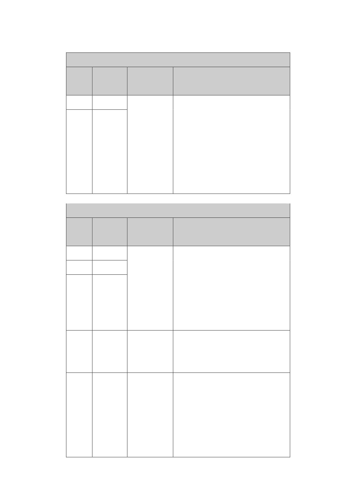
Gram5.4 XT1 power input terminal of HSV-180AS-200,300,450
XT1 power input terminal of HSV-180AS-035,050,075
Termina
NO.
Signal
Function
l Symbol
1
220A
single-phrase input terminal of
single-phr
main circuit power
ase input
AC220V/50Hz
terminal of
Main circuit power supply input
2
220B
control
terminal
power
Three phrase AC380V/ 50Hz
Gram 5.5 XT2 Heavy Current Output Terminal of HSV-180AS-200,300,450
HSV-180AS-200,300,450 XT2 heavy current input/output terminal
Termina
NO.
Signal
Function
l Symbol
1
L3
Main circuit power supply input
Three-phra
2
L2
terminal
se main
Three phrase AC380V/ 50Hz
circuit
Note:
3
L1
power input
Do not connect to the output
terminal
terminal U, V, W.
Ground terminal
Ground
4
PE
Ground resistance is less than
terminal
4Ω
Terminal P and BK is used to DC
current input or an external
Positive
braking resistor.
5
P
Of
Note:
generator
Terminal P and BK cannot be
shorted. Otherwise, the spindle
drive may be damaged.
Terminal P and BK is used to DC
current input
Negative of
Note:
6
N
generator
Terminal P and BK cannot be
shorted. Otherwise, the spindle
drive may be damaged.
There is no build-in braking
resistors, must use an external
Connection
braking resistor, terminal P and
terminal
BK must be connected to an
for
7
BK
external braking resistor.
external
Note:
braking
Terminal P and BK cannot be
resistor
shorted. Otherwise, the spindle
drive may be damaged.
U
Three-phra
V
se output
It must be linked to the motor U,
8
terminal of
V, and W terminals
W
the spindle
correspondingly.
drive
Ground terminal
Ground
9
PE
Ground resistance is less than
terminal
4Ω
Ground terminal
Ground
Ground resistance is less than
10
terminal
4Ω
Spindle drive housing ground
terminal