Series HSV-180AS AC Spindle Drive. User Manual (V1.00 2012.4) - page 3
HSV-180AS-035,050,075,100,150 XT2 heavy current input/output
terminal
Terminal
NO.
Signal
Function
Symbol
1
P
z Build-in 70Ω/500W braking
resistors.
z If only use the braking
Connect
resistor, the terminal P and
ion
BK must be disconnected to
termina
avoid short-circuit.
l for
If an external braking resistor
externa
2
BK
is used, terminal P and BK must
l
be connected to an external
braking
braking resistor.
resisto
Note:
r
Terminal P and BK cannot be
shorted. Otherwise, the spindle
drive may be damaged.
Ground
Ground terminal
4
PE
termina
Ground resistance is less than
l
4Ω
U
Three-p
V
hrase
output
It must be linked to the motor U,
8
termina
V, and W terminals
W
l of the
correspondingly.
spindle
drive

Ground
Ground terminal
9
PE
termina
Ground resistance is less than
l
4Ω
Ground terminal
Ground
Ground resistance is less than
10
termina
4Ω
l
Spindle drive housing ground
terminal
5.3.3 Side wring of main circuit input
Figure 5-6 Soldering terminal of main circuit input
1、Circuit Breaker (MCCB)
Circuit breaker must be connected between the three-phrase AC power
supply and power input terminals L1, L2, L3 on XT1 so as to cut off the
power when the spindle drive motor is over circuited or short circuited.
MCCB capacity is generally 1.5 to 2 times of the rated motor current, refer to
Table 3.1
MCCB's time characteristics should considerate the drive unit (motor rated
current 1.5 to 2 times, 1 min) and time characteristics.
Each drive unit must be corresponding to a MCCB;when multiple drive unit
share a MCCB, In order to cut off the power supply and prevent the failure
expanding,suggest using the failure chain output relay of drive unit to
control the line magnetic contactor to ensure safety。
2、leakage circuit breaker
When choosing a specific leakage circuit breaker,please select Operating
current of drive unit above 30mA.
When choosing a general leakage circuit breaker,please select Operating
current of drive unit above 200mA,time is above 0.1S。
Installing isolation transformer between a general leakage circuit breaker and
drive unit could effectively avoid the breaker malfunction
3、Line electromagnetic contactor
Line electromagnetic contactor capacity is generally 1.5 to 2 times the rated
motor current selection, please refer to Table 3.1
Frequently using open / closed magnetic contactor will cause heating of the
soft-start resistance, and even burning.
Interval time of open / closed magnetic contactor should be more than 10
minutes
4、 Surge Suppressors
In order to eliminate arc and damage, extend the life of the contactor
connect a three-phase AC interrupter serve on output main contact of electromagnetic
contactor
5、Input AC reactor
In order to protect the rectifier components from damage caused by the high-current's
impacting to the input power circuit, the power input side need to connect to an input
AC reactor and increase its power factor. It can effectively eliminate the influence of
high harmonics, prevent other equipment from damage caused by the voltage wave
changes, and eliminate the unbalanced input current caused by phase voltage
unbalanced.
Input AC reactor capacity is generally 1.5 to 2 times of the rated motor current,
please refer to the Table 3.1.
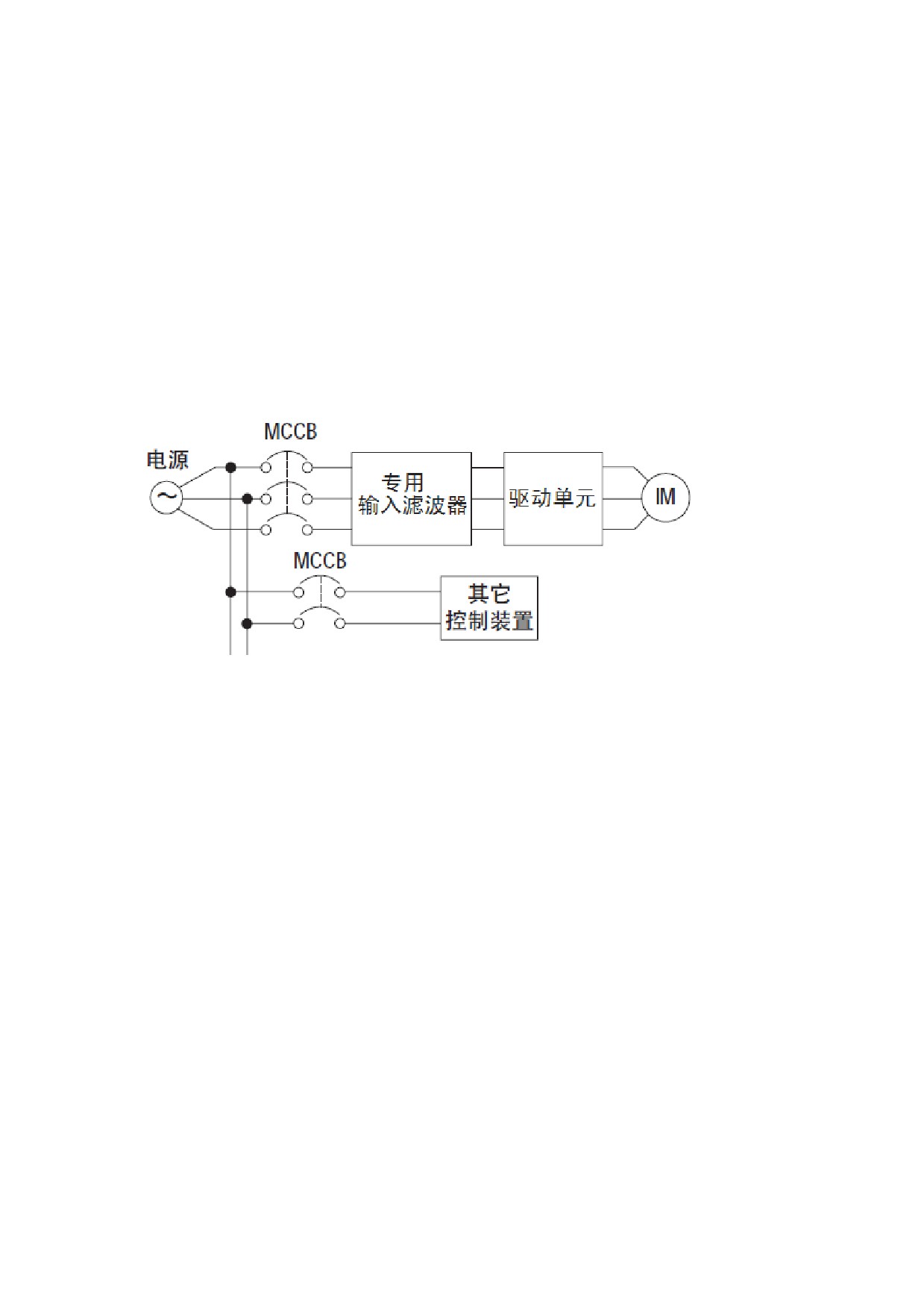
6、Input filter
In order to reduce a high-frequency interference noise from source line coupling to
drive unit, suggest install matching input filter on the current input of drive unit
Input filter capacity is generally 1.5 to 2 times the rated motor current selection,
please refer to Table 3.1.
Please select the dedicated servo (inverter) input filter。
Input filter should be well grounded
Figure 5-7 Input filter on the current input of drive unit
5.3.4 Control power wiring
HSV-180AS-200,300,450 drive unit must connect AC220Vcontrol power,during
power-on process, you should connect AC220V control power firstly and then
connect the AC380V strong electric power。
5.3.5 Output side wiring of main circuit
1、motor connection
Output terminals U、V、W of drive unit should connected to terminals U、V、W of the
three-phase AC motor according to the correct phase
If A30 motor phase sequence error alarm appears at the first running,
prompt users motor terminal phase sequence error will be wrong, you just
need to exchange V,W
Distance between drive unit and motor wiring should generally be less than
40 m
2、External Braking Resistor
The braking voltage of HSV-180AS spindle drive is DC700 V. For the maximum
braking current, see Table 3.1.
(1)A 70 Ω/500 W braking resistor has been built in HSV-180AS-035,050,
075and a maximum of five times overload is allowed (continuing for one second). An
external braking resistor is required when the drive unit's load or inertia is big. The
braking time is shorter when the load or inertia is bigger, and the resistance value is
smaller and its power is bigger. However, the maximum braking current cannot
exceed the drive's maximum braking current. Generally, the total braking power of
the braking resistor is 10% to 20% of the rated motor power.
Connect P and BK terminals of the spindle drive with the external braking
resistor if an external braking resistor is used. In this case, the internal resistor and the
external resistor are serial connected. Table 5.8 shows the recommended external
braking resistor.
(2) There is no braking resistor built in HSV-180AS-035,050,075,you have to
connect to external braking resistor. The braking time is shorter when the load or
inertia is bigger, and the resistance value is smaller and its power is bigger. However,
the maximum braking current cannot exceed the drive's maximum braking current.
Generally, the total braking power of the braking resistor is 10% to 20% of the rated
motor power.
Connect P and BK terminals of the spindle drive with the external braking
resistor if an external braking resistor is used. In this case, the internal resistor and the
external resistor are serial connected. Table 5.8 shows the recommended external
braking resistor.
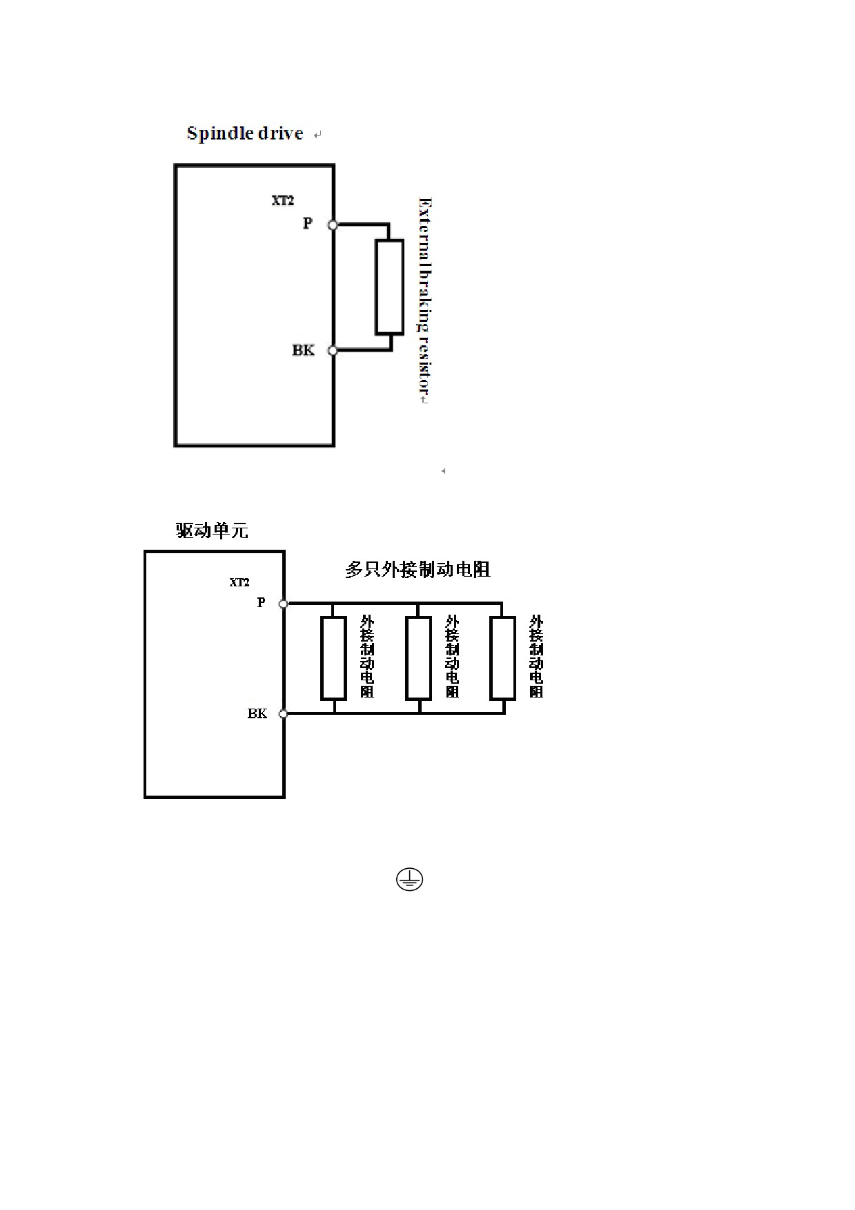
Figure 5-8 single external braking resistor standard wiring
Figure 5-9 multiple external braking resistor standard wiring
3、Ground connection
Ground terminal or PE 或
,be sure to ground。
Ground resistance is less than 4Ω
Ground wire of drive unit cann’t use with welder and other power
equipment at the same time.
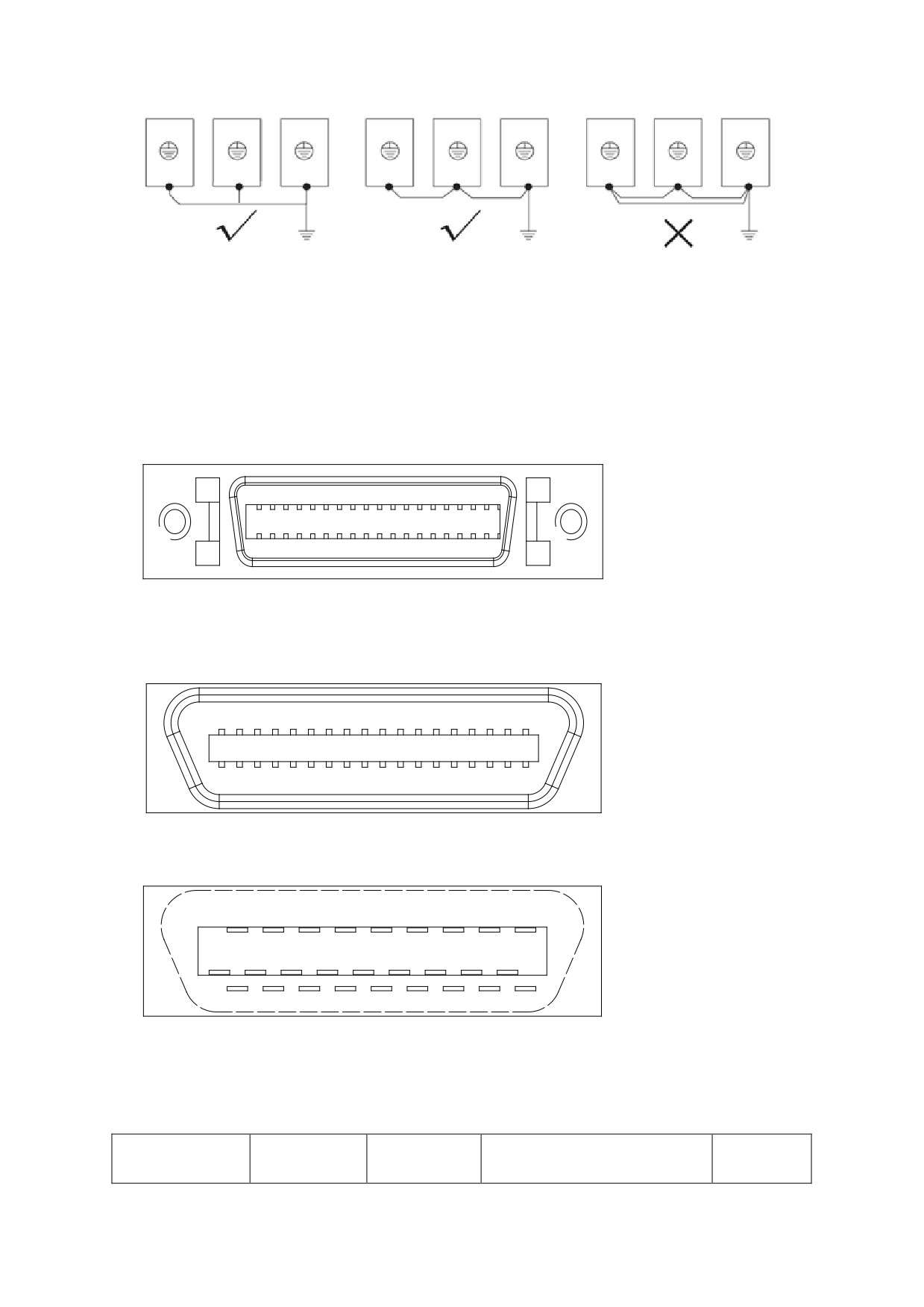
Figure 5.10 Ground connection
5.4 connection of control signal terminals
5.4.1 XS4 COMMAND input/ output terminals
Figure 5-11 XS4 command input/output interface
18
1
36
19
Figure 5-12 Plug of XS4 command input/output interface plug (looking from
the plug)
1
18
19
36
Figure 5-13Soldering terminal of XS4 command input/output interface
(looking from the soldering terminal)
18
16
14
12
10
8
6
4
2
17
15
13
11
9
7
5
3
1
36
34
32
30
28
26
24
22
20
35
33
31
29
27
25
23
21
19
5.4.1.2 XS4 COMMAND Input/output Interface
Type
Terminal
Terminal
Function
Signal
Symbol
Command pulse
14
CP+
Input terminal for
Line
input
15
CP-
external command pulse
drive
Note:
receiving
16
DIR+
You can set the pulse
RS422
17
input mode by setting the
standard
movement parameter
PA--22.
Command pulse +
DIR-
characters
CCW/CW command pulse
mode
2-phase command pulse
mode
Spindle motor
32
A+
line
Encoder A output
optic-electri
33
A-
drive
cal encoder
18
B+
output
Encoder B output
36
B-
RS422
35
Z+
standard
Encoder Z output
34
Z-
PNP
Z-phase pulse output
21,22
Z_OUT
output
100mA
NPN
Z-phase pulse output
31
ZPLS_OUT
output
100mA
23,24
GNDDM
Digital signal ground
0V
Analog output
Analog output terminal
DC -10~
terminal
12
AN+
+10Vor
0~+10V
Reference terminal for
13
AN-
analog input
27,28
GNDAM
Analog signal ground
0V
SW input
Spindle enable input
0Vcommon
signal
terminal
point
EN ON:Enable the spindle
0V input
drive
effectiv
1
EN
EN OFF:The spindle drive
e
stops working, and the
motor is idle.
Alarm clear input
terminal
2
ALM_RST
ACL ON: Clear system
alarm
ACL OFF: Keep system
alarm
Spindle forward rotation
input terminal
FWD ON: Spindle motor
3
FWD
running forward
FWD OFF: Spindle motor
stops running forward
Reverse rotation input
terminal
REW ON: Spindle motor
4
REW
running reverse.
REW OFF: Spindle motor
stops running reverse.
INC_Sel1
Input terminal for
selecting indexing
5
incremental
orientation angular
ratio
INC_Sel
INC_Sel
ra
1
2
ti
o
6
INC_Sel2
ON
ON
4
OFF
ON
3
ON
OFF
2
OFF
OFF
1
Spindle orientation
ready input
ORN ON: indicates that
spindle orientation is
25
ORN
begin
ORN OFF: indicates that
spindle orientation is
cancelled。
Switch input terminal
for control mode
switching
When the spindle running
under the external
26
Mode_SW
analog speed mode, the
operating mode can be
switched to C-axis
position control via
this switch.
The effectiveness can be
tested by STA-8 (STA-8:
0 indicates ineffective,
1 indicates effective)
Mode_SW ON:Spindle is
running under the
position mode.
Mode_SW OFF:Spindle is
running under the
external speed mode.
Input terminal for
indexing incremental
orientation
In the orientation mode,
Mode_SW is used to
control the indexing
incremental
orientation.
Each time the Mode_SW
turned to ON, the spindle
moves a preset angle
along with the
orientating direction.
The angle is determined
according to the value of
PA-40 as well as the
terminal INC_Sel1 and
INC_Sel2.
SW output
Zero-speed reached input
NPN
signal
When the running speed is
output10
in the specified
0mA
zero-speed range (by
7
ZSP
setting movement
parameter PA-29), the
zero-speed reached input
is connected.
Spindle ready output
terminal
READY ON: indicates
8
READY
proper power supply, and
no drive alarm. The
signal is connected.
READY OFF: indicates the
main power is not
switched on or a spindle
drive alarm is reported.
The signal is
disconnected.
Spindle alarm output
terminal
ALM ON: indicates a
spindle drive alarm is
9
ALM
reported. The signal is
connected.
ALM OFF: indicates no
spindle drive alarm. The
signal is disconnected.
Speed-reached output
terminal
When the speed error is
within or less than the
29
GET
preset speed error range
(specified by movement
parameter PA-11), the
signal is connected.
Spindle
orientation-finished
output terminal
In the spindle
orientation mode, when
the error between the
actual spindle position
and the preset spindle
orientation position
(specified by movement
30
ORN_FIN
parameter PA-39) is less
than or equal to the
preset spindle
orientation-finished
range (specified by the
movement parameter
PA-37), the signal is
connected (ORN_FIN ON).
When the spindle
orientation is
cancelled(ORN is
switched to OFF), the
signal is disconnected
(ORN_FIN OFF).
Public terminal of XS4
0V
terminal switch-value
19,20
COM
input/output signal
5.4.1.3 XS4 COMMAND Input / Output Interface
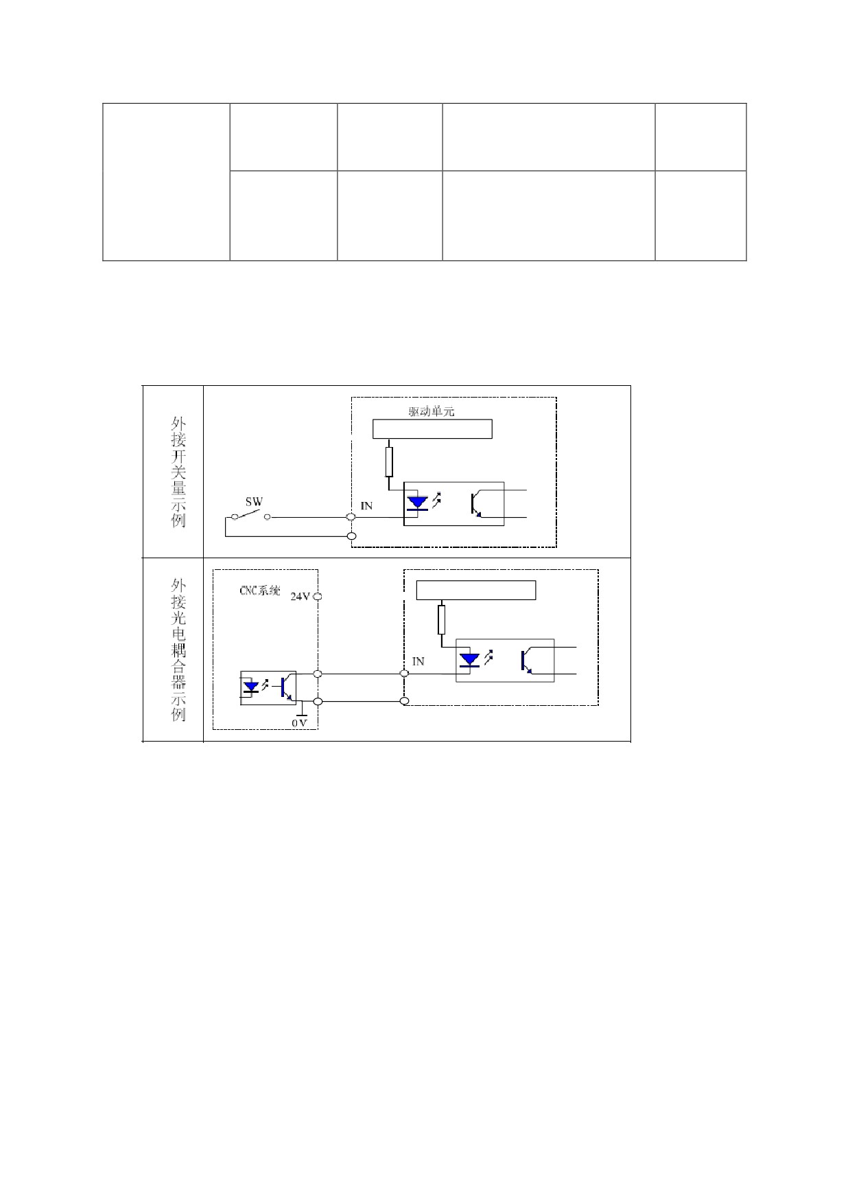
1、Switch-value Input Interface
Figure 5-14 Switch-value input interfaces of HSV-180AS
内部提供+24V
4.7K
COM
内部提供+24V
4.7K
驱动单元
COM
Note:
1、 Two common wiring example,IN means input point:(EN,ALM_RST,FWD,
REW,INC_Sel1,INC_Sel2,Mode_SW,ORN)
2、The COM signal of the XS4 command input/output interface must be
connected to the power ground of the external DC24V power supply.
Otherwise, the spindle drive may work improperly.
3、The Darlington transistor is served as the output transistor which needs
to be connected to a relay or an optical coupler.The external power supply
is provided by users. Make sure that the polarity is not reversed.
Otherwise, it may damage the spindle drive.
4、XS4 command input / output interface of the COM signal must be connected
with the ground signal of external DC24V,otherwise drive unit cannot
work properly.
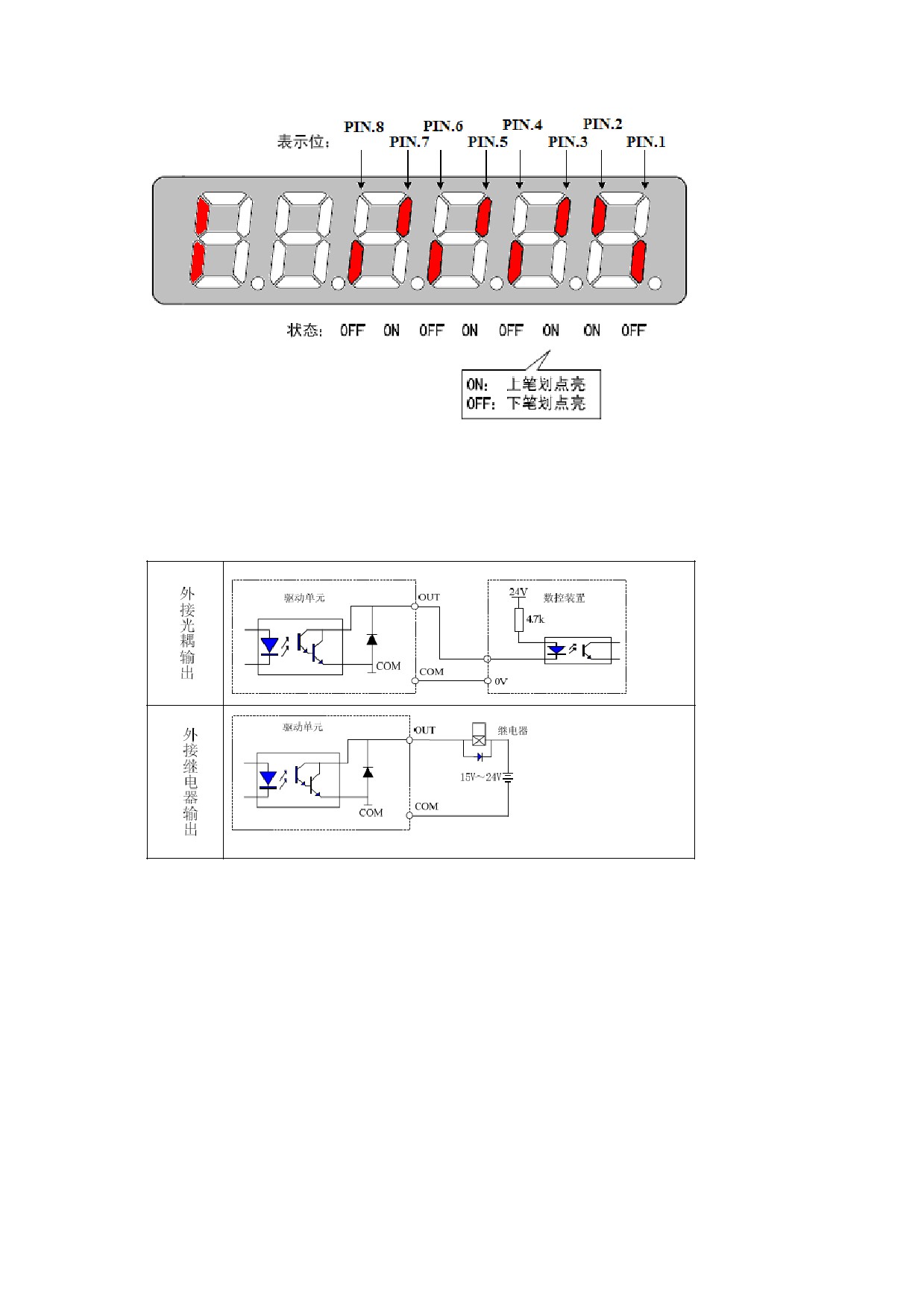
Figure 5-15 Status of switch output signal
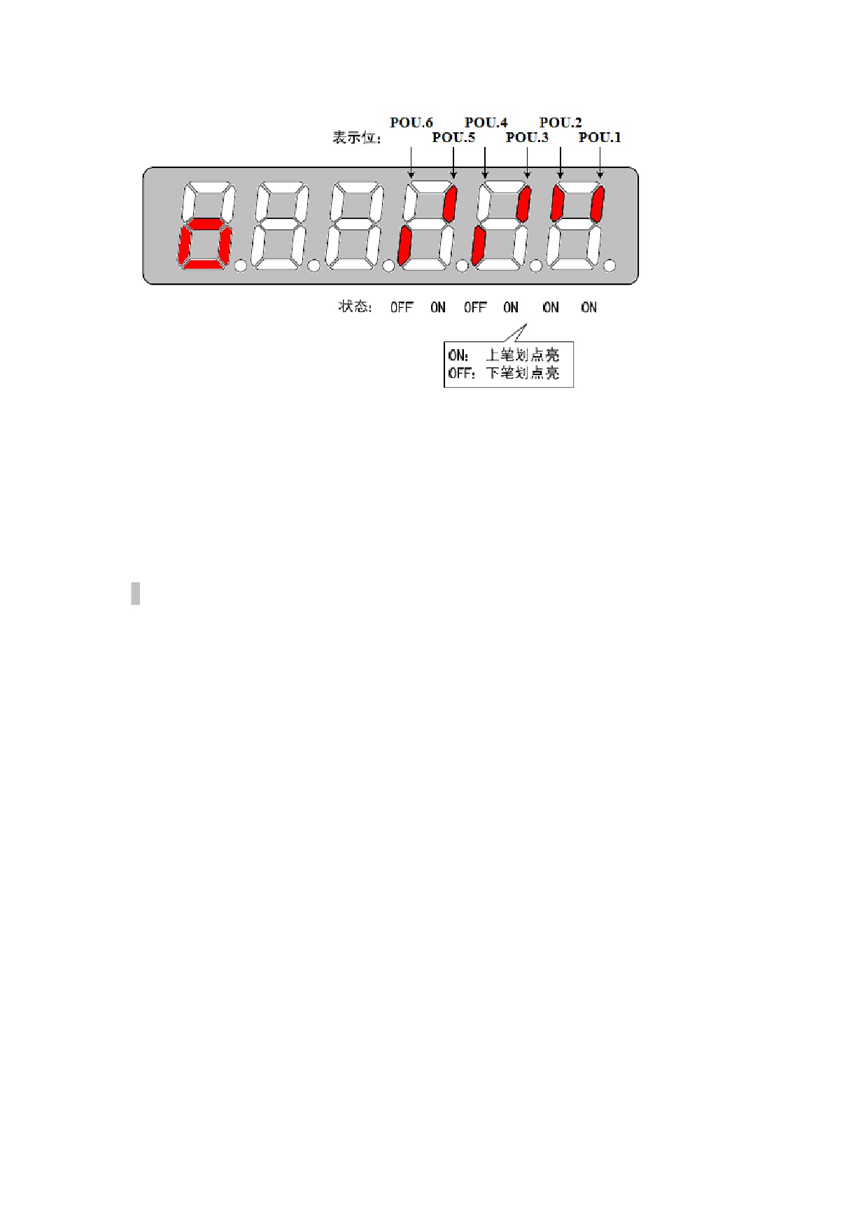
2、Switch-value Output Interface
1.Two common wiring example,OUT means out point:(ZSP,READY,ALM,
GET,ORN_FIN)。
Figure 5-16 Connections of switch output signal
2.Input mode: NPN. The input switch-value state is determined by the
spindle drive. When the input of isolation optical coupler is conducted,
the input switch -value state is ON. When the input of isolation optical
coupler is turned off, the input switch-value state is OFF
3.It provides open-collector output, with a maximum of 100 mA current and
25 V external power supply voltage. Therefore, the load of the
switch-value output signal must meet the requirements. If the value
exceeds the maximum value or the output terminal is directly connected
to the power supply, it may damage the spindle drive.
4.If the load is an inductance load such as relay, it must be anti-parallel
with the freewheeling diode (FWD) at both ends. The FWD cannot be reversed.
Otherwise, it may damage the spindle drive.
5.The output transistor is Darlington Transistor. When it is conducted,
the voltage drop between the collector and the emitter (Vce) is about 1V,
which cannot meet the requirement of the TTL low level. So it cannot be
directly connected to the TTL.
NOTE:
The output switch-value state is determined by the spindle drive. When
the output of Darlington Transistor is connected, the output switch-value
state is ON. When the output of Darlington Transistor is disconnected,
the output switch-value state is OFF.
The state of the spindle alarm output switch (ALM) is the exception. When
the output of Darlington Transistor is connected, the state of ALM is OFF,
otherwise, it is ON.
3、Z-phase Pulse Open Collector Output Interface
(1)Incremental photoelectric encoder Z signal send to the CNC system by
open collector, meanwhile providing two types of output :Z_OUT(PNP)and
ZPLS_OUT(NPN)
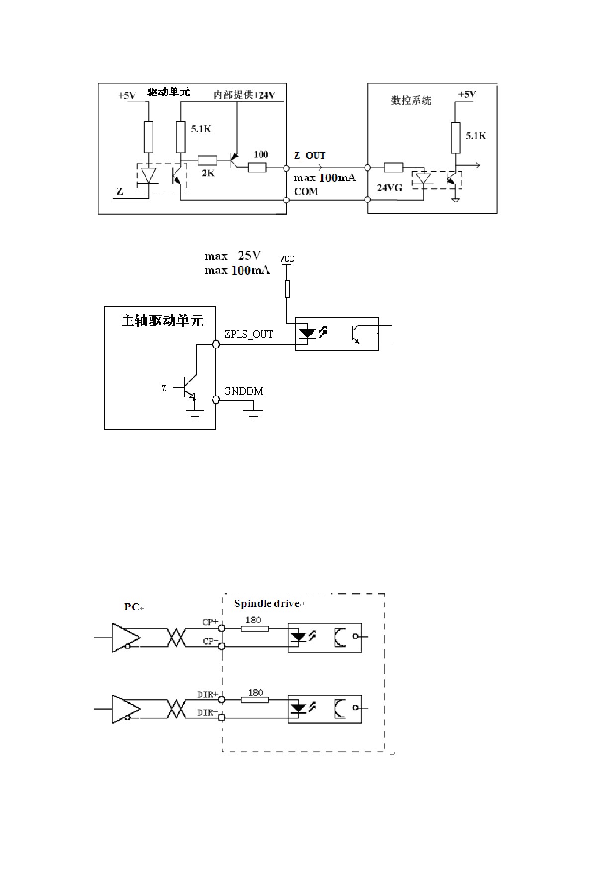
Figure 5-18Z-phase pulse open-collector output interface(PNP)
Figure 5-19Z-phase pulse open-collector output interface(NPN)
(2)Z-phase pulse signal is outputted by the open-collector.,with a
maximum of 100mA current
(3)The Z-phase pulse signal is usually very narrow. Therefore the PC
must use a high-speed optical coupler receiver, such as 6N137.
(4)The output must be non-isolated output (non-insulated).
4、 Pulse Command Input Interface
Figure 5-20 Differential drive mode of the pulse input
Figure 5-21 Single-ended drive mode of the pulse input
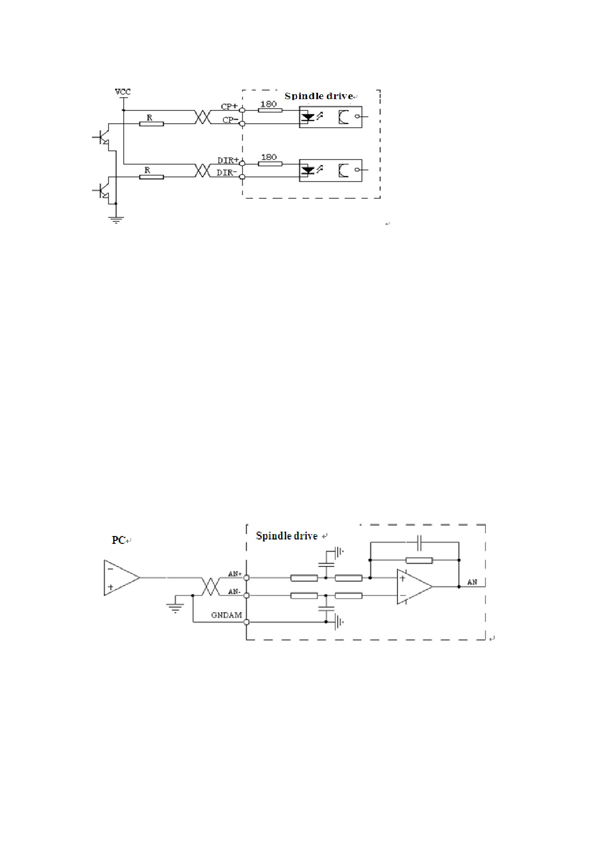
It is recommended that you use the differential drive mode (especially
when the cable is too long) which uses AM26LS31, MC3487 drives or RS422
drives.
The single- ended drive mode can reduce the action frequency. You can
determine the value of R according to a 10 to 15 mA drive current and a
maximum of 25V external power supply voltage.
Generally, if the value of VCC is 24 V, the value of R is 1.3 K to 2 K
(VCC = 24 V, R = 1.3 K to 2 K);
If the value of VCC is 12 V, the value of R is 510 Ω to 820 Ω (VCC =
12 V, R = 510 Ω to 820 Ω);
If the value of VCC is 5 V, the value of R is 82 Ω to 120 Ω (VCC = 5
V, R = 82 Ω to 120 Ω).
In the single-ended mode, users provide the external power supply. Make
sure that the polarity is not reversed. Otherwise, it may damage the
spindle drive.
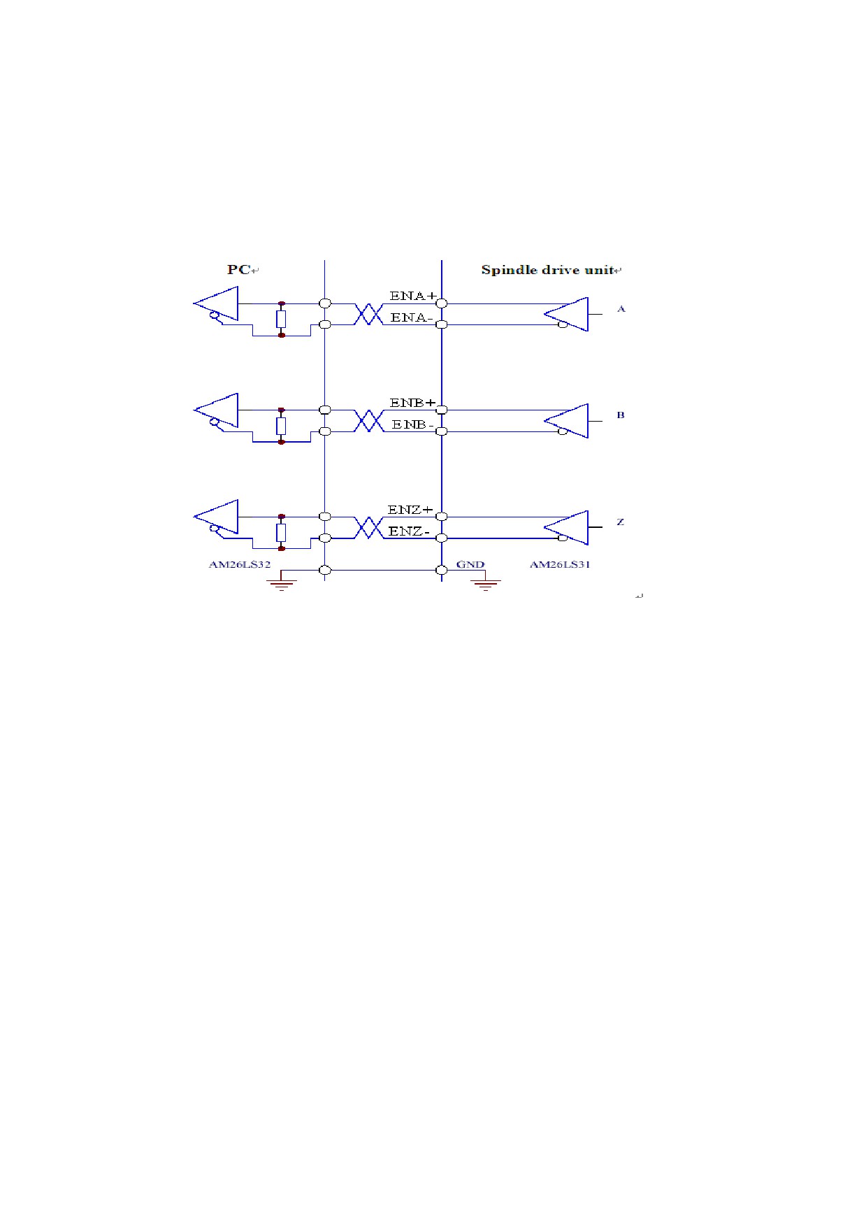
5、 Analog Command Input Interface
Figure 5-22 Differential analog input interface
Figure5-23 Single-ended analog input interface

Figure 5-24 c Differential analog potentiometer input interface
Figure 5-25 d Single-ended analog potentiometer input interface
The analog input interface is differential. According to different
connection methods, it has two forms connection, differential connection
and single-ended connection. The range of input voltage is -10V to +10V.
In the differential connection, the analog ground wire is connected to
the input reference terminal at the side of controller. Therefore, it
needs three wires to connect the controller and drive unit.(see Figure
5-13 a)
In the single-ended connection, the analog ground wire is connected to
the input reference terminal at the side of the drive. Therefore, it needs
two wires to connect the controller and the drive.(see Figure 5-13 b)
The differential connection is superior to the signal-ended connection
for its good anti-common-mode interference characteristic.
The input voltage cannot exceed the range from -10V to +10V. Otherwise
it may damage the spindle drive.
It is recommended that the shield cable be used to reduce the noise
disturbance.
It is normal for the analog input interface has a zero bias which can be
compensated by setting the movement parameter PA-8.
The analog interface is non-isolated.
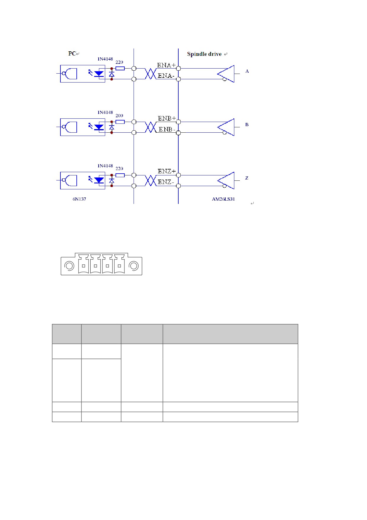
6、Spindle Motor optic-electrical encoder/Spindle Encoder Output Interface
Figure 5-26 Spindle motor optic-electrical encoder/spindle encoder
output interface
The encoder signal is outputted by the differential drive(AM26LS31).
The controller input terminal can adopt AM26LS32 receiver and must be
connected to an approximate 330Ω termination resistor.
The controller ground wire and the drive ground wire must be reliably
connected.
The output must be non-isolated output.
The controller input terminal can also adopt an optical coupler receiver.
However, the receiver must be a high-speed optical coupler, such as 6N137.
Figure 5-27 Spindle motor optic-electrical encoder/spindle encoder
output interface
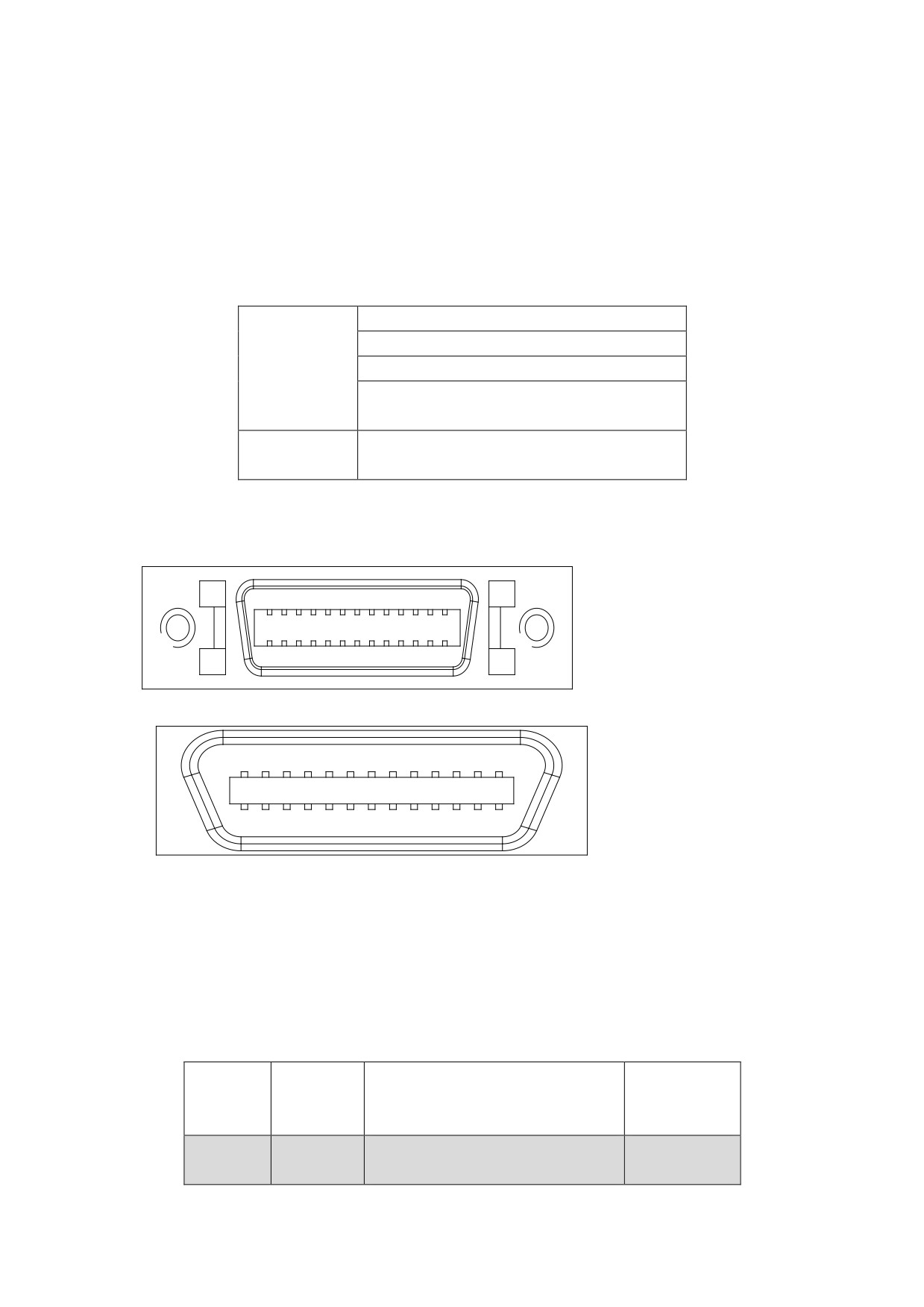
5.4.2 XS5 Input/output Terminal
XS5 Input/output Terminal Figure
4
3
2
1
Figure 5.25 XS5 Input/output Termina
5.4.2.2 XS5 I/O Input/output Terminal Function
Terminal
NO.
Signal
Function
Symbol
Failure chain output terminal
1
MC1
The relay is connected when the relay
Failure
is in the Normal Open state and the
chain
spindle drive runs properly. The
2
MC2
relay is disconnected if there is any
spindle drive faults.
3
COM
Reserved
4
BREAK
Reserved
5.4.2.3 XS5 I/O Input/output Terminal Notations
(1)If the output terminal of the drive inductive loads, such as
electromagnetic relays, electromagnetic contactor, should be retrofitted
surge suppressor.
The surge suppressors should be nearby installed on end of electromagnetic
relay or electromagnetic contactor coil
5.5Connection of the encoder signal terminal
5.5.1 XS3 ENCODER1 Spindle Motor Input Interface
HSV-180AS support three types of motor encoder:Incremental photoelectric
encoder、Sine and cosine incremental encoder、ENDAT2.1/2.2of Absolute
encoder。Details are as follows:
1.Number of encoder lines is 1024
2.Number of encoder lines is 2048
Incremental
3.Number of encoder lines is 2500
encoder
4.Sine and cosine incremental
encoder
Absolute
NDAT2.1/2.2of Absolute encoder
encoder
5.5.1.1 XS3 ENCODER1 Spindle Motor Input Interface Figure
Figure 5-29 XS3 Spindle Motor Input interface plug
13
1
26
14
Figure 5-30 XS3 Spindle Motor Input interface plug (looking from the plug)
1
13
14
26
Figure 5-31 Soldering terminal of XS3 Spindle Motor Input interface plug
(looking from the soldering terminal)
5.5.1.2 XS3 ENCODER1 Spindle Motor Input Interface Fuction
1、Spindle drive unit connect incremental photoelectric encoder
Chart5.8 signal function of XS3 ENCODER1 connect Incremental
photoelectric encoder
Symbol
Terminal
NO
Function
standard
Symbol
Spindle motor encoder
Line driver
1
A+/SINA+
feedback A+ input
receive
Spindle motor encoder
RS422
2
A-/SINA-
feedback A- input
standard
Spindle motor encoder
3
B+/COSB+
feedback B+input
Spindle motor encoder
4
B-/COSB-
feedback B- input
Spindle motor encoder
5
Z+
feedback Z+(or R+) input
Spindle motor encoder
6
Z-
feedback Z-(or R-) input
7,8
Reserved
9,10
Reserved
11,12
Reserved
13
OH1
Motor overheat detection
Input terminal
26
OH2
It is connect to the motor
overheat detection sensor
Spindle motor encoder +5V
power output terminal
Connect the spindle motor
16,17
optical-electrical encoder
+5V
18,19
with 5 V power supply. If the
DC
cable is too long, use
+5V/150mA
multiple wires to form
serial connection.
23,24,2
Spindle encoder power
GNDD
5
ground 0V
20,22
Reserved
21
Reserved
Shield ground
14,15
PE
It is connected to the motor
housing
NOTE:The homonyms pin connected has been shorting together in the internal
circuit board
The spindle drive unit connect sine and cosine incremental encoder
Chart5.9 Signal function of XS3 ENCODER1 connectSine and cosine
incremental encoder
Symbol
Terminal
NO
Function
standard
Symbol
Spindle motor encoder
1
A+/SINA+
feedback SINA+ input
Spindle motor encoder
2
A-/SINA-
feedback SINA- input
Line driver
Spindle motor encoder
3
B+/COSB+
receive
feedback COSB+input
RS422
Spindle motor encoder
4
B-/COSB-
standard
feedback COSB- input
Spindle motor encoder
5
Z+
feedback Z+(or R+) input
Spindle motor encoder
6
Z-
feedback Z-(or R-) input
7,8
Reserved
9,10
Reserved
11,12
Reserved
13
OH1
Motor overheat detection
Input terminal.
26
OH2
It is connect to the motor
overheat detection sensor
Spindle motor encoder +5V
power output terminal
Connect the spindle motor
16,17
optical-electrical encoder
+5V
18,19
with 5 V power supply. If the
DC
cable is too long, use
+5V/150mA
multiple wires to form
serial connection.
23,24,2
Spindle encoder power
GNDD
5
ground 0V
20,22
Reserved
21
Reserved
Shield ground
14,15
PE
It is connected to the motor
housing
NOTE:The homonyms pin connected has been shorting together in the internal
circuit board
Spindle drive unit connect ENDAT2.1 agreement of Absolute encoder
Chart5.10 Signal function of XS3 ENCODER1 connect ENDAT2.1 agreement of
Absolute encoder
NO.
Terminal
Function
Symbol
Symbol
standard
Spindle motor encoder
1
A+/SINA+
feedback SINA+ input
Spindle motor encoder
2
A-/SINA-
feedback SINA- input
Line driver
Spindle motor encoder
3
B+/COSB+
receive
feedback COSB+input
RS422
Spindle motor encoder
4
B-/COSB-
standard
feedback COSB- input
Spindle motor encoder
7
U+/DATA+
feedback DATA+ input
Spindle motor encoder
8
U-/DATA-
feedback DATA- input
V+/CLOCK
Spindle motor encoder
9
+
feedback CLOCK+ input
V-/CLOCK
Spindle motor encoder
10
-
feedback CLOCK- input
5,6
Reserved
11,12
Reserved
13
OH1
Motor overheat detection
Input terminal
26
OH2
It is connect to the motor
overheat detection sensor
Spindle motor encoder +5V
power output terminal
Connect the spindle motor
16,17
optical-electrical encoder
+5V
18,19
with 5 V power supply. If the
DC
cable is too long, use
+5V/150mA
multiple wires to form
serial connection.
23,24,2
Spindle encoder power
GNDD
5
ground 0V
20,22
Reserved
21
Reserved
Shield ground
14,15
PE
It is connected to the motor
housing
NOTE:The homonyms pin connected has been shorting together in the internal
circuit board
5.5.1.3 XS3 ENCODER1 spindle motor encoder input interface wiring
diagram
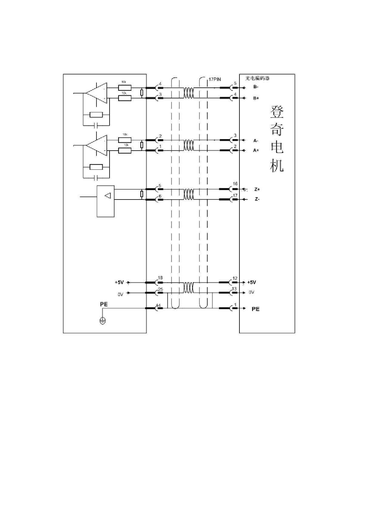
1、Spindle drive connect with Incremental photoelectric encoder and
Dench motor
2、Spindle drive connect with ENDAT2.1 agreement of Absolute encoder
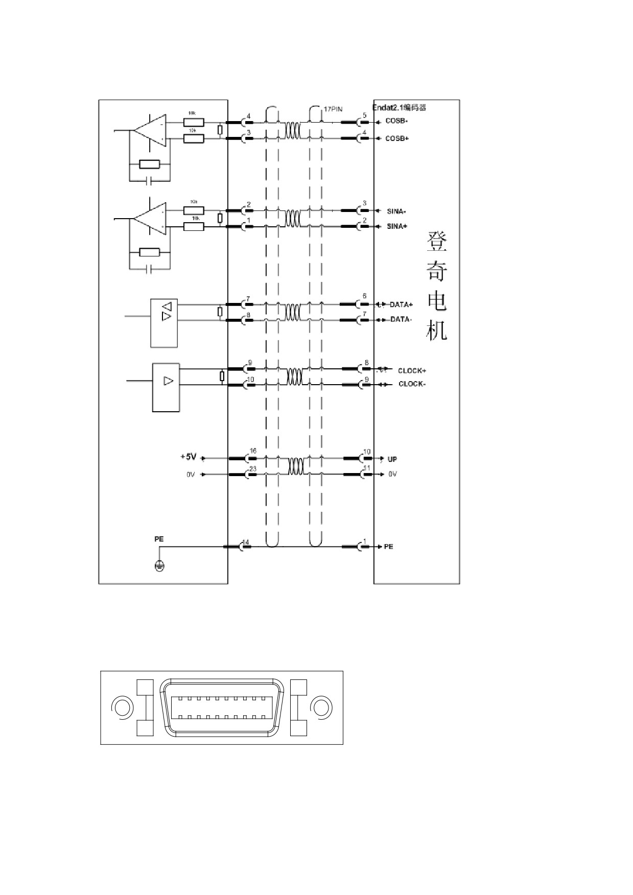
and Dench motor
XS2 ENCODER2 Spindle Encoder Input Interface
5.5.2.1XS2 ENCODER2 Spindle Encoder Input Interface Figure
Figure 5-34 XS2 Spindle Encoder Input interface plug
10
1
20
11
Figure 5-35 XS2 Spindle Encoder Input interface plug(looking from the
plug)
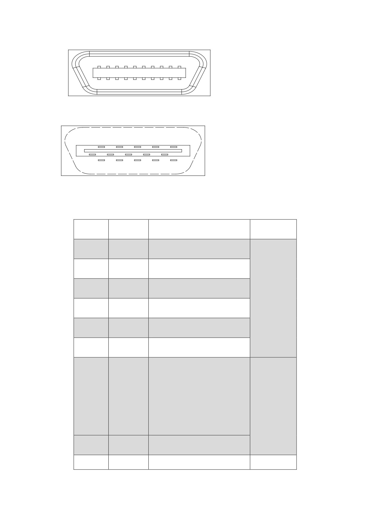
1
10
11
20
Figure 5-36 Soldering terminal of XS2 Spindle Encode Input interface plug
(looking from the soldering terminal)
8
6
4
2
109
7
5
3
1
2019
1817
1615
1413
1211
XS2 ENCODER2 Spindle Encoder Input Interface Function
1、Drive spindle connect to Incremental photoelectric encoder
Figure 5.11 Signal function of XS2 ENCODER2 connect Incremental
photoelectric encoder
Terminal
Symbol
NO
Function
Symbol
standard
Spindle motor encoder
11,12
A+/SINA+
feedback A+ input
Spindle motor encoder
1,2
A-/SINA-
feedback A- input
Line driver
Spindle motor encoder
13,14
B+/COSB+
receiver
feedback B+input
RS422
Spindle motor encoder
3,4
B-/COSB-
standard
feedback B- input
Spindle motor encoder
15,16
Z+/DATA+
feedback Z+input
Spindle motor encoder
5,6
Z-/DATA-
feedback Z-input
Spindle motor encoder +5V
power output terminal
Connect the spindle motor
optical-electrical
7,8
+5V
encoder with 5 V power
DC
supply. If the cable is too
+5V/150mA
long, use multiple wires to
form serial connection.
Spindle encoder power
9,10
GNDD
ground 0V
19
CLOCK+
Reserved
20
CLOCK-
Shield ground
17,18
PE
It is connected to the
motor housing
5.6 Connection of the communication signal terminal
5.6.1 XS1 Serial Interface
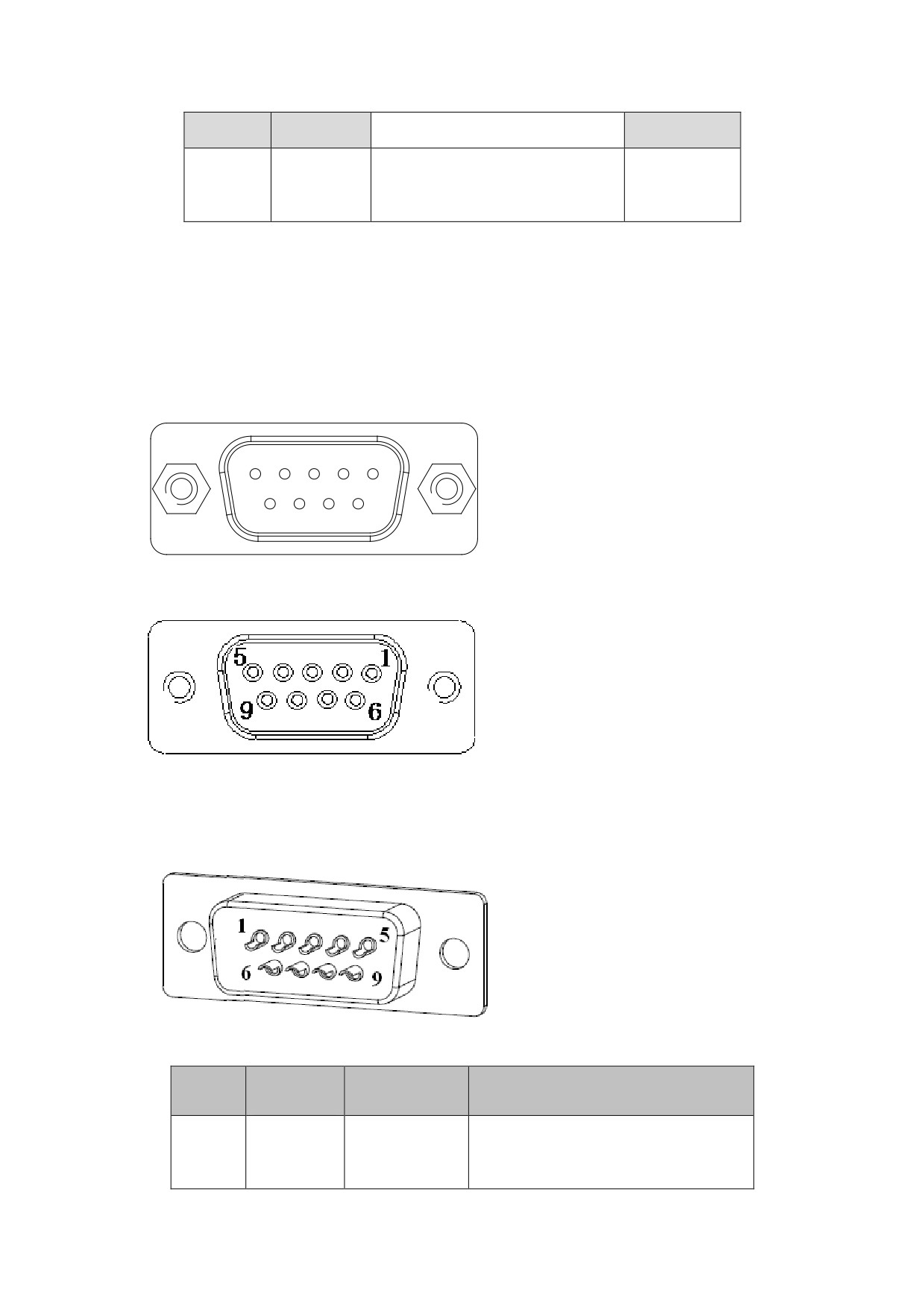
Figure 5-37 XS1 Serial interface plug
1
5
6
9
Figure 5-38 XS1 Serial interface plug (looking from the soldering plug)
Figure 5-39 Soldering terminal of XS1 Serial interface plug (looking from
the soldering terminal)
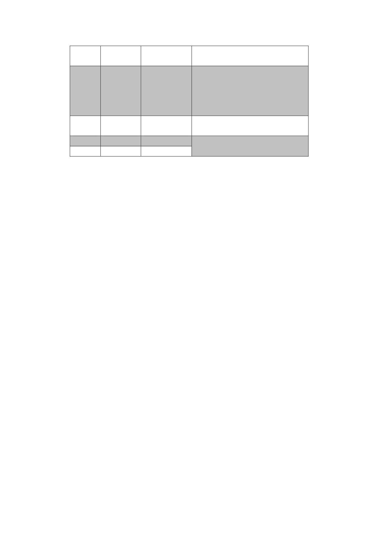
Figur5.12 Function of the communication signal terminal XS1
Terminal
NO.
Signal
Function
Symbol
RS232 Data
It is connected to the serial
2
TX
transmissio
data receiving interface (RX)
n
of the controller or PC to
achieve the serial
communication.
It is connected to the serial
RS232
data transmitting interface
3
RX
Data
(TX) on the controller or PC to
reception
achieve the serial
communication.
Signal
1,5
GNDD
Data signal ground
ground
4
CANL
Reserved
6
CANH
Reserved
5.7 Wiring
Power input terminal XT1, and heavy current power output terminal XT2
Diameter
The terminal diameters of P,BK,L3,L2,L1,U,V,W, PE on TX1、TX2 of
HSV-180S-025,035,050,075≥2.5mm2
(2.2 kw).
The terminal diameters of P,BK,L3,L2,L1,U,V,W, PE on TX1、TX2 of
HSV-180S-025,035,050,075≥4 mm2 (3.0/3.7/5.5/7.5 kw).
Grounding
Grounding wire must be thick. The spindle drive and spindle motor must
be connected to PE.
Grounding resistance <4Ω
Use cold pre-insulated terminals to connect terminals and make sure that
the connection is firm.
Install the non-fuse circuit breaker to promptly cut off the external
power when a spindle drive fault occurs.
It is recommended that the power is supplied after passing the input AC
power reactor and input filter to improving the anti-jamming capability.
It is recommended that shield cable be used to prevent other electrical
equipments from interference.
Control signal XS4, feedback signal XS3 for spindle motor
optic-electrical encoder, spindle encoder feedback signal XS2, and XS1
Serial Interface
Diameter
Shield cable is used (stranded shield cable is the best choice), and the
cross-sectional area is greater than or equal to 0.12mm2 (AWG24-26). The
shielded layer must be connected to the metal shell of the connection plug.
Cable length

The cable must be short. The length of the control signal cable XS4 is
not greater than 10 meters, and the length of the feedback signal cable
XS2, XS3 is no more than 40 meters.
Wiring
The wiring must be away from the electric power circuit to prevent
interference.
Install surge absorbers with inductive components (coils) of related
circuits. Freewheeling diodes are antiparallel connected to the DC coils,
and RC absorbed circuits are paralleling connected to the AC coils.
3、I/O input/output terminal XS5
(1)Diameter: use ordinary cable or shielded cable, wire cross-sectional area
≥ 1.5mm2.
(2)Cable length: cable length as short as possible and not more than 10
meters.
5.8 Standard Wiring
Caution
U, V, W on XT2 must be connected to the motor windings in
corresponding order and cannot be reversed.
Cables and wires must be fixed and cannot be near the radiator
of the spindle drive or motor. Otherwise, the insulation
properties may be reduced due to overheat.
In the spindle drive, large-capacity of electrolytic capacitor
exists, which leads to the remaining of high voltage even after
power off. Therefore, do not touch the spindle drive or motor
within five minutes after the power off.
Terminals P, BK on XT2 are connected to the external braking
resistor.
Terminal P and BK cannot be shorted. Otherwise it will damage the
spindle drive.
“Shell” in the wiring diagram refers to the mental shell of the
wiring plug. The cable shield must be connected to the metal shell.
First unravel the shield and avoid twisting together. Then loop
part of the shield and cut off the rest. Last cover the looped
shield with casing, and weld the exposed shield to the metal shell.
Avoid too much solder to make sure the plug shield can be covered.
It will be better, if you use a metal cable clip to form a
360-degree access and perform nearby grounded.
5.8.1 Standard Wiring for Position Control Mode (Pulse
Interface)
Figure 5-40 Standard wiring for position control mode (pulse interface)