HNC-818. User Manual - page 4
5. Program Editing and Management
2.
Press the CS SET key, then the value which can be figured out in
accordance with the measured values and the measurement mode, is
set to the displayed workpiece coordinate system offset. The
defined axis can only be the one that have values in the
measurement position.
3.
Press the CS key to select one of the coordinate systems from G54
to G59 to define.
4.
Press G54.X. In the input box, enter X value to define the required
coordinate system. Valid value: 0-60.
5.
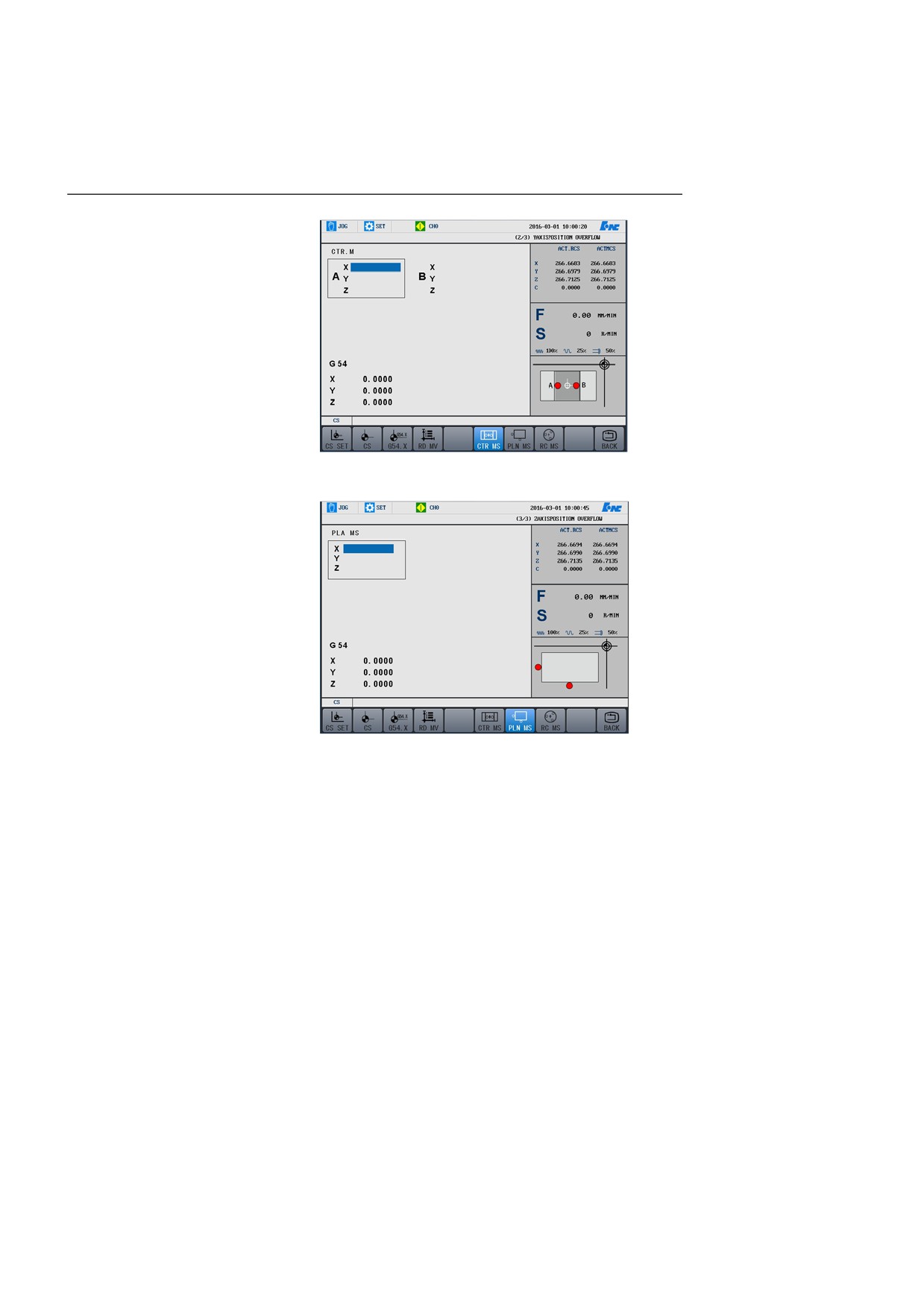
Press CTR MS: Enter the center measurement mode (by default).
6.
Press PLN MS: Enter the plane measurement mode.
7.
Press RC MS: Enter the circle center measurement mode.
Description
Operations on three measurement modes:
1.
Center measurement
The measurement value display area is divided into Point A and
Point B. The default selection box is Point A; The default axis is the
X-axis; The background color is blue. Use the cursor keys to select
the axis to be measured, and the left and right keys to select Point A
or B.
Press the RD MV key, the system inputs the coordinate value
corresponding to the machine actual position into the selected box
with blue background, and automatically moves the selected box to
the Point B.
Press the CS SET key. Then the value, which the system figures out
via the formula of (measured value of point A + measured value of
point B)/2 for the defined axis, is displayed the specified coordinate
in area 2. If only the point A is measured while the point B is not
measured, the system displays the message "reading measurement
value failed".
94
5. Program Editing and Management
2.
Plane measurement
Only one point coordinate is displayed in the measurement value
display area. The X axis is selected by default. The part to be edited
is in blue background. You may use the Up and Down keys to move
the cursor to the required axis.
Press the RDMV key, then the system inputs the corresponding
coordinate value of the machine actual position into the coordinate
of area 1. Press the CS SET key, then the axis whose value has been
read is set to the specified coordinate of area 2.
3.
Circle Center Measurement
Point A, B, C are displayed in the measurement value display area.
The default plane is G17, default axes are X, Y axis. The X and Y
coordinates of point A are in the selection box with blue background.
You may move the cursor to the Plane and select the drop-down
box, click Enter, and select G17, G18, and G19 planes.
95
5. Program Editing and Management
The corresponding Coordinate are XY, XZ, and YZ.
Press the RD MV key, enter the corresponding coordinate value of
the machine actual position into the selected box with blue
background, and the selected box automatically moves to the next
point.
Press the CS SET key, then the system calculates the circle center
based on the three points, and input the calculated value to the
specified coordinate system of the area 2.
If one of the three point coordinate is not measured, the system
displays the message "Measurement failed"
96
6. Operation Control
6 Operation Control
This chapter includes the following sections:
Start, Pause and Stop
Dry Running
Over-Block Operation
Optional Stop
Single Block Operation
Breakpoint Related Operation
Operation Control
97
6. Operation Control
6.1 Start, Pause and Stop
6.1.1 Start Auto-Operation
After a program file is loaded and verified, you may start the auto
operation function.
1.
Press the Auto key (the indicator is on) on the operation panel to
enter the auto operation mode.
2.
Press the Start button (the indicator is on) on the operation panel to
automatically run the loaded program.
6.1.2 Pause Auto-Operation
During program operation, follow the instructions below to pause the
on-going operation:
1.
During program operation, press the Feed Hold key (the indicator
is on) to enter the Feed Hold mode and pause the on-going
operation.
2.
Press the Start button (the indicator is on) to proceed with the auto
operation.
6.1.3 Stop the Auto-Operation
Operation procedure
During auto operation, you may Follow the instructions below to stop the
auto operation:
1.
During program operation, press the feed hold key (the indicator is
lit) to enter the Feed Hold mode and pause the on-going operation.
2.
Press the Manual key to disable the M and S command functions.
3.
If you want to exit the system, press the Emergency Stop key to
stop the running program.
4.
If you want to stop the running program but do not want to exit the
98
6. Operation Control
system, press Prog
→ Reset,
and reload a program.
99
6. Operation Control
6.2 Dry Running
Attention
This function is invalid to thread cutting.
Dry running can be activated only in the non-automatic or non-single
block mode.
panel (the indicator is on), and the CNC system enters the dry running
mode. The feed rate specified in the program is ignored, and the feed
motion is at the dry running speed specified by the parameter. The feed
rate is limited by the maximum machining speed and controlled by the
feed override.
The Dry Running function does not conduct actual cutting, and is
intended to confirm the cutting path and program.
During the actual cutting, you need to disable the function; otherwise, it
may causes damages.
Click the key on the machine control
100

6. Operation Control
6.3 Over-Block Operation
If the over-block symbol “/” exists in the program. Press the key during
program running, the system will automatically skip the block of the
program beginning with the "/" symbol. Release the key to disable the
over-block operation.
101
6. Operation Control
6.4 Optional Stop
If the M01 auxiliary command is used in the program, you may press the
key to stop the program at the line of M01. Press the Start button to
continue the program. Release this key to disable the M01 command
function.
102
6. Operation Control
6.5 Single Block Operation
Press the key to enter the Single Block mode
(the corresponding
indicator is on). The program will be executed block by block.
1.
Press the Start button to execute a block of the program. The
motion slows to stop and the tool stops when the block is finished.
2.
Press the Start button again to execute the next block of the
program. After the block is completed, the operation stops.
103
6. Operation Control
6.6 Breakpoint Related Operation
During machining, there are always some large workpieces which
requires complicated operation and long duration. It is necessary to save
and restore the breakpoint for further processing. In other words, you
may save the breakpoint (let the system remember various status of the
time point) before cut the power supply. After a period of time, you turn
on the power supply and restore the breakpoint (let the system restore the
status where the processing is broken) to proceed with the machining
from the breakpoint.
6.6.1 Save the Breakpoint
Operation procedure
1.
Press the feed hold key to enter the feed hold mode (the indicator is
on).
2.
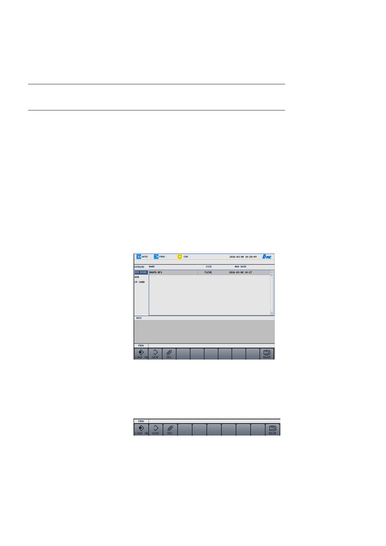
Press Prog → BP.
3.
Use the▲ and ▼ keys to select a storage path (press Enter to view
the folders in the selected storage path).
4.
Press Enter, and the system will automatically create a file named
with the current program name. You may modify the name as
required.
5.
Press Enter to confirm the operation.
104
6. Operation Control
6.6.2 Resume Breakpoint
Operation procedure
1.
If the power is off after you save the breakpoint, you need to return
the tool back to the reference point after power on. Otherwise,
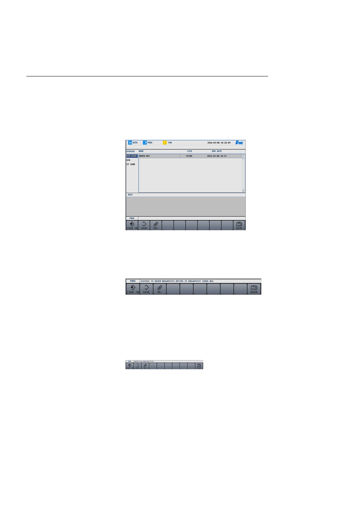
directly press Prog → BP.
2.
Use the cursor keys to select the directory where the target file is,
switch to the file list, and select the breakpoint file to be loaded.
3.
Press LOAD IN, the system will resume the breakpoint of the
program based on the information saved in the breakpoint file.
6.6.3 Delete Breakpoint
Operation procedure
1.
Press Prog → BP, and select a breakpoint file.
2.
Press the DEL key, and the message as shown in the figure below is
displayed:
3.
Press Y or Enter to delete the breakpoint file, or press N to cancel
the deletion.
Note: The deleted file cannot be restored.
6.6.4 Return to Breakpoint
105
6. Operation Control
If axis motion has been conducted after breakpoint saving, you need to
return the axis to the position of breakpoint before proceeding the
program from the breakpoint. Follow the instructions below:
Operation procedure
1.
Manually move the axis near to the breakpoint, and make sure no
collision will occur when the tool returns to the breakpoint.
2.
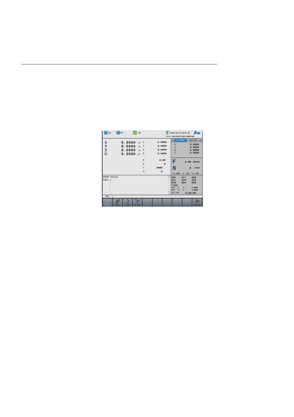
Under the MDI main menu, press TO BP. The system
automatically displays the breakpoint file information.
3.
Press Start to start running, and the system moves the tool to the
breakpoint.
4.
Press the Start button to proceed program from the breakpoint.
Attention
Before returning to the breakpoint, you need to load the corresponding
program; otherwise, the system may prompt you that the breakpoint
cannot be resumed.
106
6. Operation Control
6.7 Intervention at runtime
6.7.1 Feed Rate Adjustment
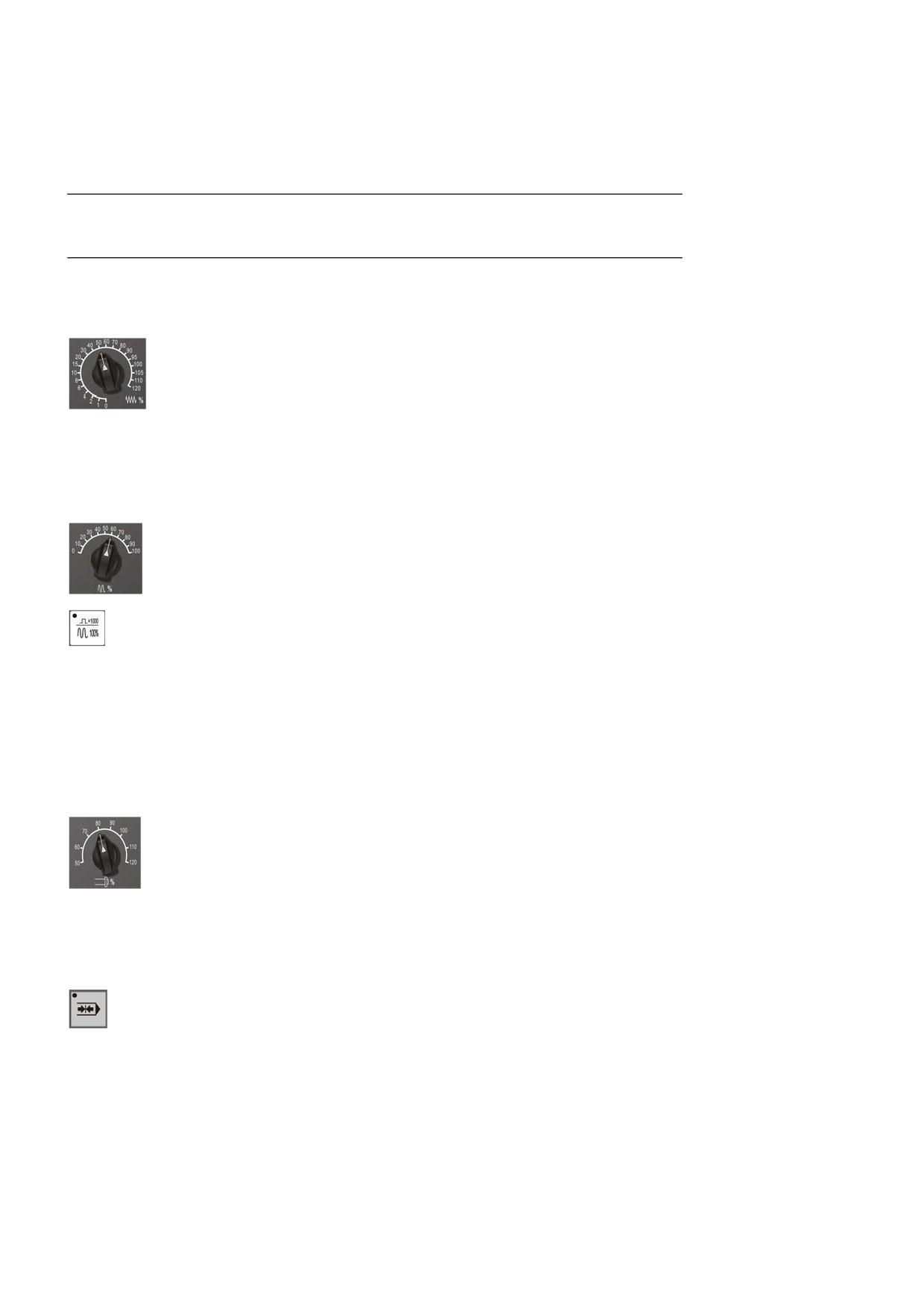
In the Auto or MDI mode, adjust the feed rate by using the override keys
when the feed rate of the F-code programming is too high or too low.
The adjustment range is 0% to 120%.
In the manual continuous feed mode, this button can be used to adjust the
manual feed rate.
6.7.2 Rapid Traverse Speed Adjustment
speed adjustment are different based on control panel.
1.
In the auto or MDI mode, rotate the rapid traverse speed adjustment
button to adjust the feed specified in the program. The range of
adjustment is from 0% to 100%.
2.
In the auto or MDI mode, press the corresponding override ratio
keys to adjust the rapid traverse speed.
The operations on rapid traverse
6.7.3 Spindle Override Adjustment
The spindle clockwise/counter clockwise speed can be adjusted by
spindle override.
Rotate the spindle speed adjustment button to adjust the spindle speed,
which ranges between 50% and 120%. The spindle speed cannot be
adjusted during mechanical gear change.
6.7.4 Machine Lock
This function is used to disable the machine coordinate axis motion.
In the manual mode, click the key (the indicator is on). The system
simulatively runs the program in the Auto mode without machine motion.
The axis position information changes on the screen, but the movement
107
6. Operation Control
commands from servo axis are not
run. This function is used to verify programs.
output. Hence, the machine does not
Attention
1.
The tool does not move to the reference point even the G28, G29
functions are enabled.
2.
The function is invalid during the auto operation.
3.
During the simulative operation, the machine lock function can be
canceled only when the simulation is completed.
4.
You need to return the tool to the reference point every time after
the function is executed.
108
7. Position Information
7 Position Information
This chapter includes the following sections:
Coordinate Display
Text Display
Graph Display
Joint Display
109
7. Position Information
7.1 Coordinate Display
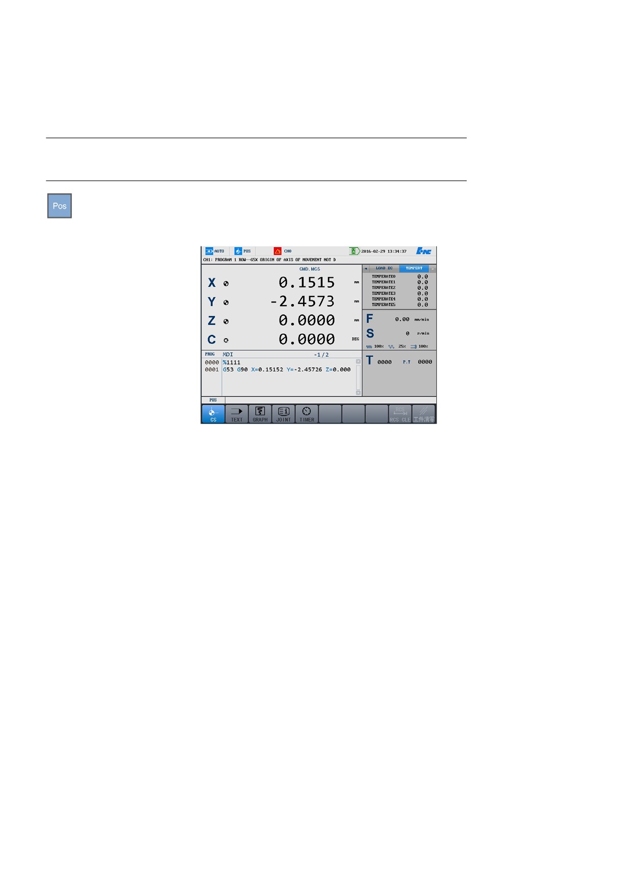
During program running, press POS
→ CS to view the position
information of the current program shown in different indication. See the
figure below:
You may press TIMER to change the tool information interface at the
right lower part (valid for milling machines).
Attention
Press Set → PARA → DISPLAY PARAMETER to select the displayed
indication. See section 4.5.2.
110
7. Position Information
7.2 Text Display
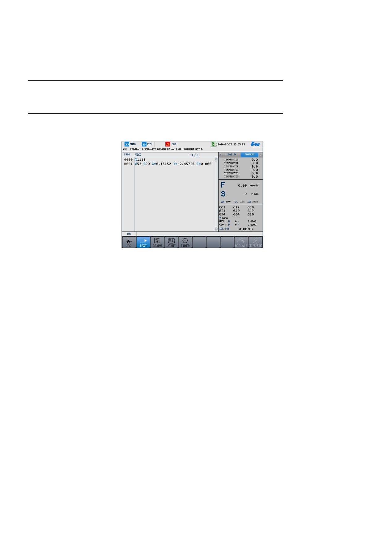
Operation procedure
→ TEXT to view the G codes, coordinate system information, M
commands, and feed rate F. See the figure below:
Press TIMER to change the machining information interface at the right
lower part (valid for milling machines).
During program running, press POS
Attention
Set the G code display mode to 3, and the line number displayed in the
program is
9999 (for detailed information, see HNC-8 Parameters
Description.
111
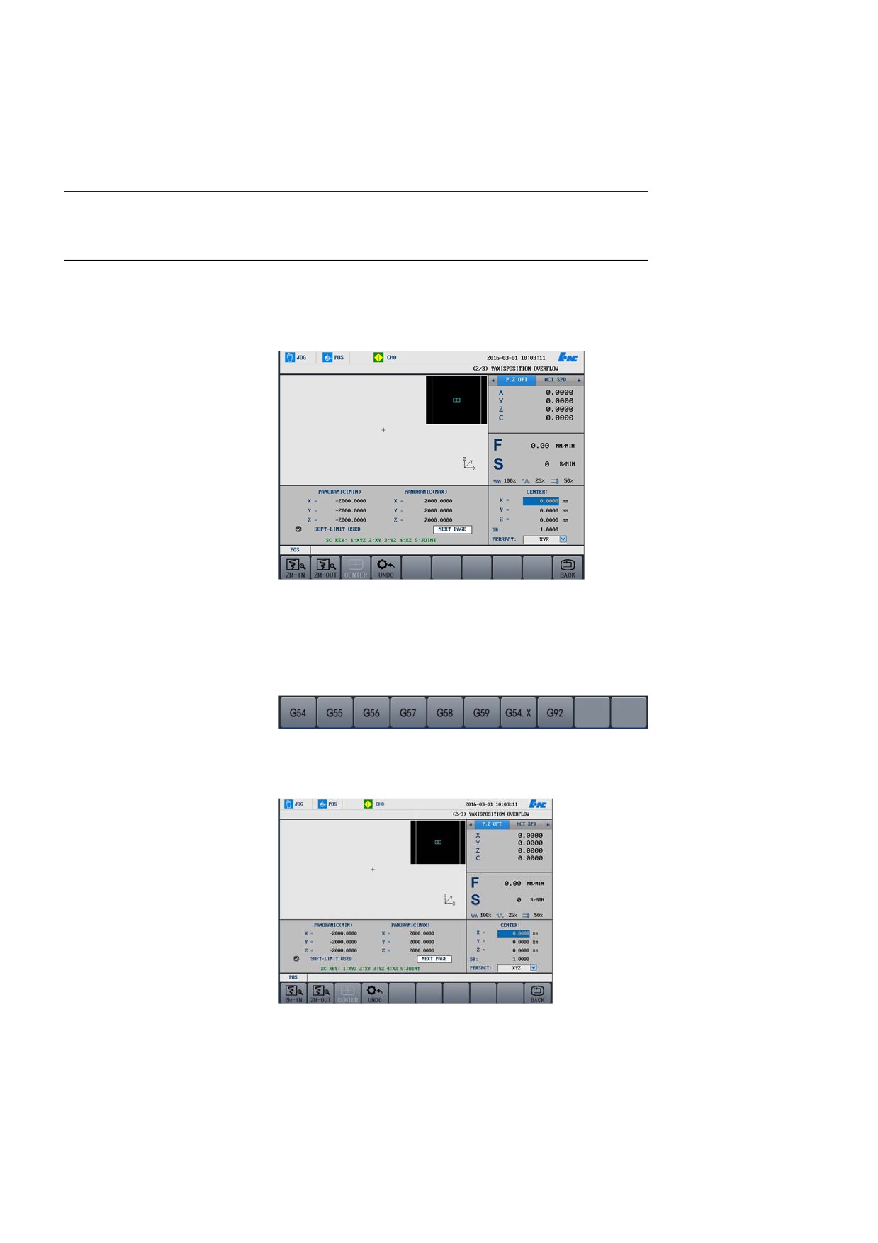
7. Position Information
7.3 Graph Display
During program running, press POS
→ GRAPH to simulate the
machining process.
Coordinate System
1.
Set the coordinate system (see section 4.3.2), e.g. G54 X10 Y20
Z30
2.
Press POS → GRAPH → CS to select a coordinate system, and
press G54.
3.
The XYZ value of the graph center is displayed at the right lower
part.
Graph settings
112
7. Position Information
1.
Press POS → GRAPH → GRAPH SET. You may manually set
the graph center, display scale, and display modes.
2.
Move the cursor to select an item to set.
3.
Press Enter to enter the editing mode.
4.
Press Enter again to confirm the operation.
Define graph center
1.
Press POS → GRAPH → CENTER.
2.
Move the cursor to manually define the graph center.
Attention: The center can be defined in the XY, XZ, YZ modes.
Restore settings
1.
Press POS → GRAPH → UNDO.
2.
The system prompts you whether to restore the settings (Y/N).
3.
Press Y to restore the settings or press N to cancel the restoring.
Graph display mode
You may use the shortcut keys to change the graph display modes.
[Switch view]: Press 1, 2, 3, 4, 5 to switch among different display
modes:
-
1: XYZ
-
2: XY
-
3: YZ
-
4: XZ
-
5: the four modes above simultaneously
[Zoom in/out graph]: Press PgUp or PgDn.
-
PgUp: Zoom in the graph
-
PgDn: Zoom out the graph
[Rotate graph]: Press +, -, ►, ◄, ▲, or ▼
-
+/-: Rotate the graph around the Y axis
-
►/◄: Rotate the graph around the Z axis
-
▲/▼: Rotate the graph around the X axis
Attention
The graph cannot be set during program running.
113
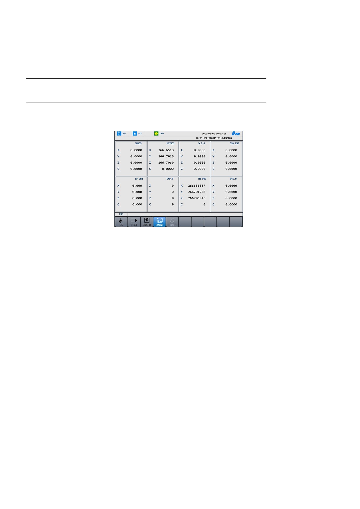
7. Position Information
7.4 Joint Display
Operation procedure
During program running, press POS → JOINT to display eight kinds of
position information.
114
8. Diagnosis
8 Diagnosis
This chapter includes the following sections:
Alarm Display
Alarm History
Ladder Monitoring
Oscilloscope
Input and Output
Status Display
Macro Variables
Servo Adjustment
Machining Information
Version
115
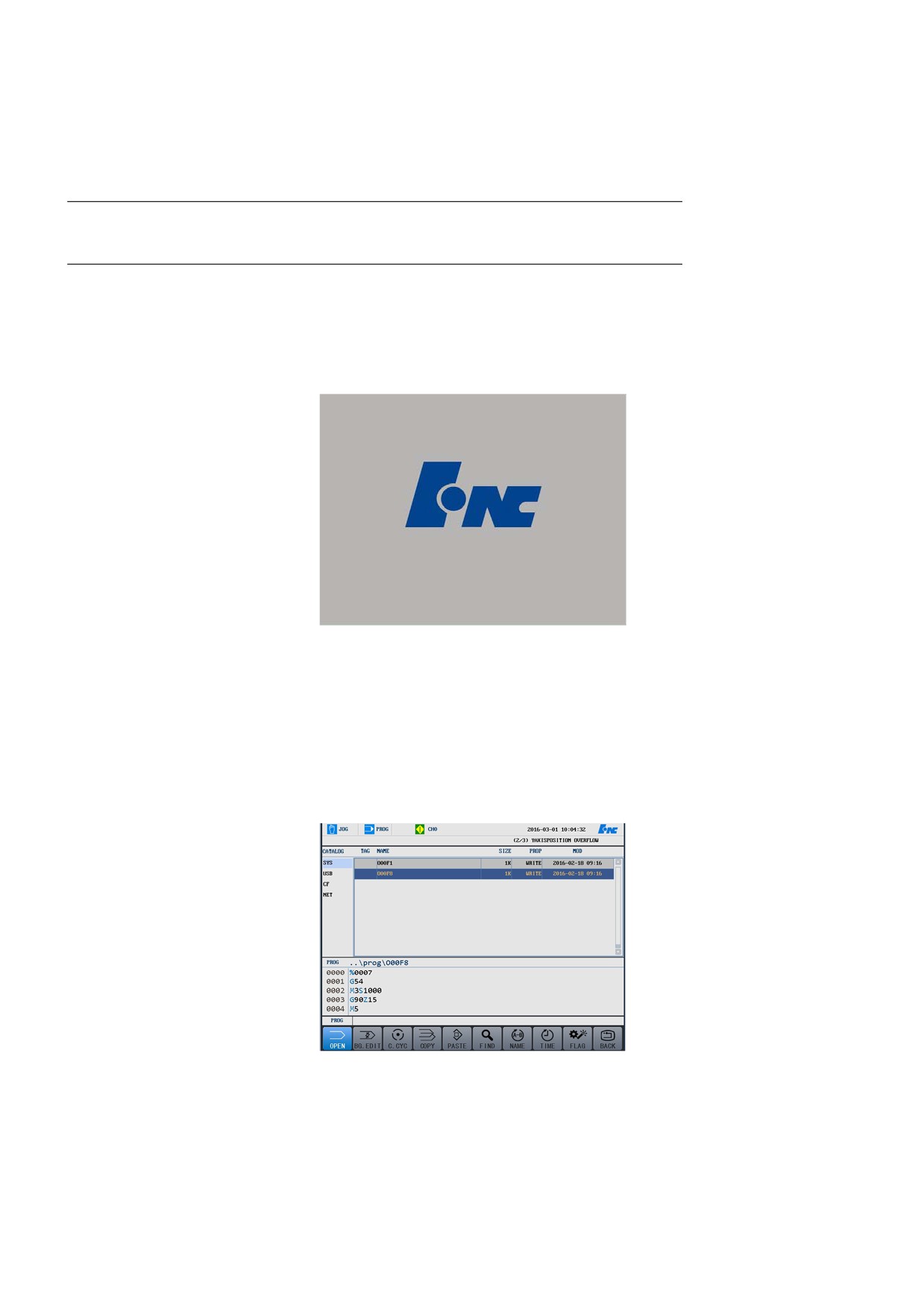
8. Diagnosis
8.1 Import System Logo Interface
Function description
You may change the logo on the booting interface and application
interface through the USB loading.
There are two logo pictures.
1.
Booting logo
Picture standard:
1)
BMP format
2)
800*600 pixel
3)
24-bit true color
4)
File name: init_hcnc.bmp (Case sensitive)
2.
Small system logo
116
8. Diagnosis
Picture standard:
1)
BMP format
2)
52*24 pixel
3)
24-bit true color
4)
File name: logo.bmp (Case sensitive)
Operation method
1.
Create the LOGO picture based on the specified standard.
2.
Enter the permission of Machine manufacturer or above, and the
LOAD LOGO menu will be displayed under Dgn → VER.
3.
Click LOAD LOGO to load the logo restart the system.
117
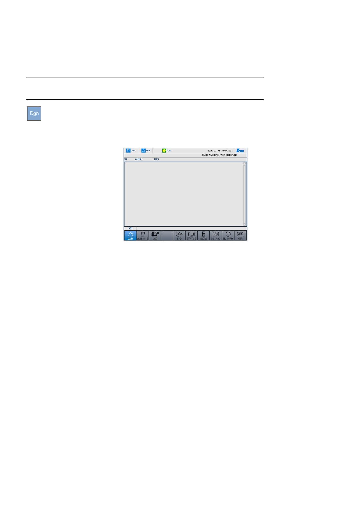
8. Diagnosis
8.2 Alarm Display
If an error occurs during system running or processing, the message
"ALARM" will be displayed on the screen. You may press this key to
check the detailed warning messages.
1.
Press Dgn → ALM.
2.
Use ▲, ▼, PgUp and PgDn to view alarm information.
118
8. Diagnosis
8.3 Alarm History
8.3.1 Operation Procedure
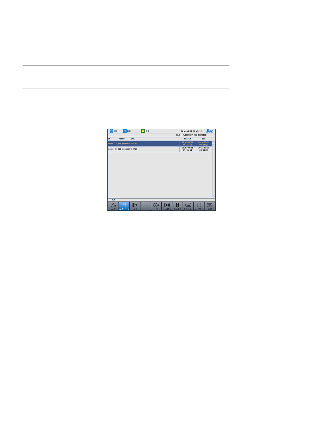
1.
Press Dgn → ALM HIS to display the alarm history.
2.
Use ▲, ▼, PgUp and PgDn to view the alarm history.
8.3.2 Machining Status Recorded during Alarms
Overview
information of the last 10 machine alarms after the machine is booted.
Record the machining status
Function description
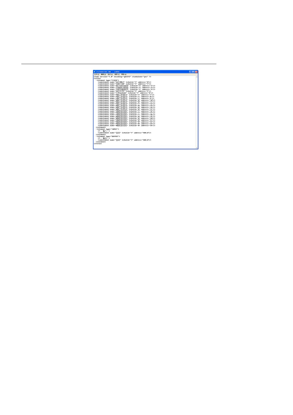
The recorded machining status information can be divided into fixed
information and configuration information. All recorded information
needs to be configured in the STATERECORD.XML file under the data
directory.
The format of the configuration file is as below:
119
8. Diagnosis
FIXED---Fixed status
It is not recommended that you modify the name and address properties
in this status. You may modify the value of isValid: the value 0 indicates
the status is valid while 1 indicates the status is valid.
INPUT---Input port status
Example:
<subelement name="automatic input" isValid="1"
address="480.0"/>input port X480.0: name indicates the name of the
input port, address indicates the address of the input port, and isValid
indicates whether the status is valid.
OUTPUT---Output port status
Example:
<subelement name="automatic output” isValid="1"
address="480.0"/> output Y480.0: name indicates the name of the output
port, address indicates the address of the output port, and isValid
indicates whether the status is valid.
A maximum of 24 records can be configured for one alarm.
The configured STATE RECORD.XML file in the data directory can
be created into the BTF upgrade package, which can be imported to the
CNC system by upgrading.
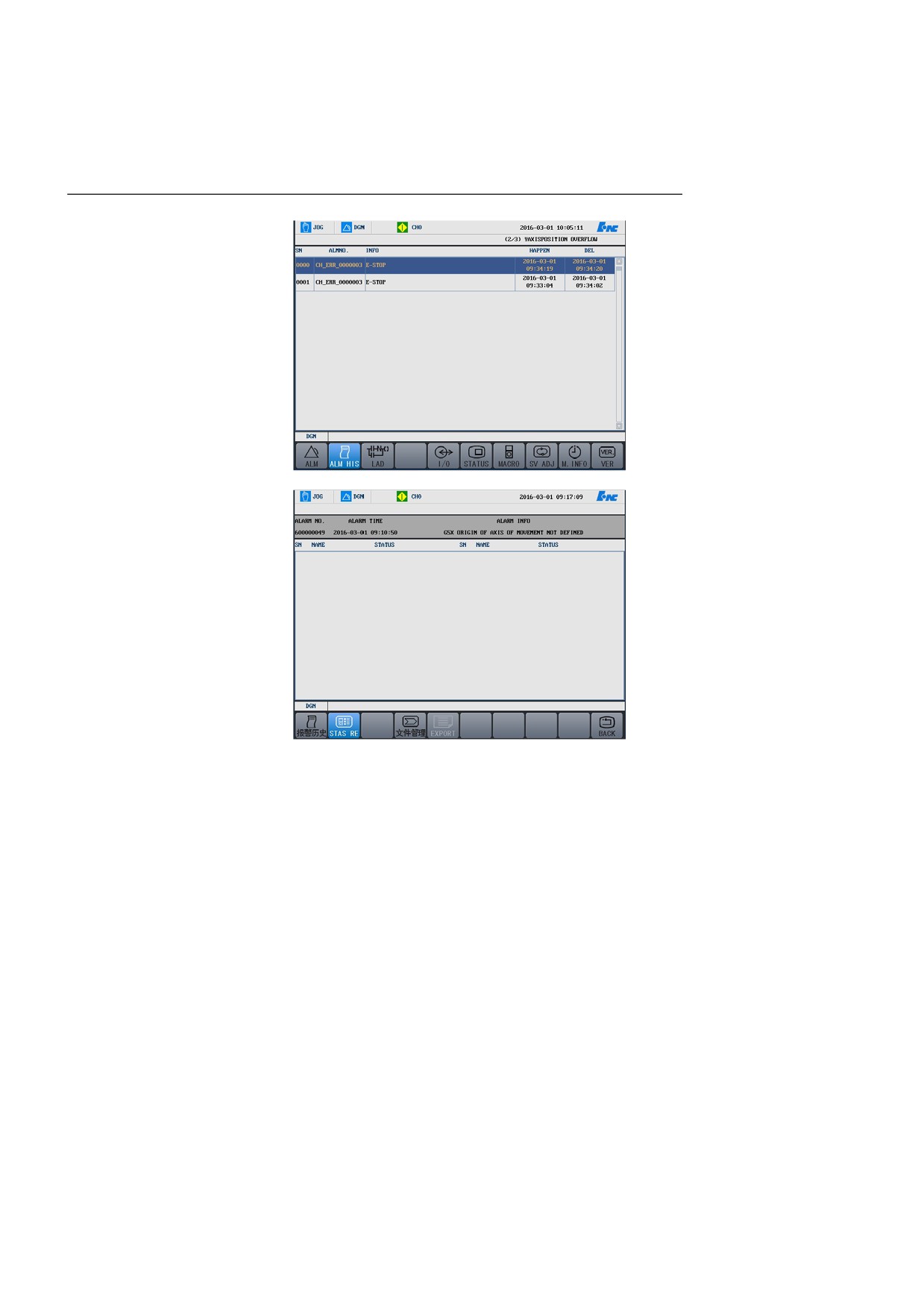
On the ALM HIS interface, select an alarm, and press Enter to view the
status information corresponding to the alarm. See the figure below:
120
8. Diagnosis
121
8. Diagnosis
8.4 Ladder Monitoring
8.4.1 Ladder Diagnosis
Operation procedure
1.
Press Dgn → LAD → LAD Dgn to view the value of each variable.
2.
The system displays the value in decimal by default. You can press
the hexadecimal function key, and the system displays the value in
hexadecimal.
3.
Use the cursor keys to select an element.
4.
Press the NOT ALLOW or ALLOW key to shied or activate the
element.
5.
Press UNDO to cancel the shielding or activating operation.
6.
You may enter an element name in the search box, press Enter to
search the element. You may press PgUp or PgDn to search for the
element with the same name up or down.
8.4.2 Ladder Modification
Attention
The function is available only to the machine manufacturer, CNC
manufacturer and administrator.
Search
1.
Press Dgn → LAD → FIND, enter the element name, and press
Enter to search for the element.
2.
Use PgUp or PgDn to search for the element with the same name
up or down.
Modify
1.
Press Dgn → LAD → EDIT.
2.
Use the cursor keys to select an element, and press Enter to enter
the editing status.
3.
Enter the element value in the editing box.
4.
Press Enter again to complete the editing.
122
8. Diagnosis
5.
Press the functional keys corresponding to the EDIT menu to create
element.
y Straight line: insert straight line
y Vertical line: insert vertical line
y Delete element: delete elements
y Delete vertical line: delete vertical lines
y Normally open: normally open contacts
y Normally closed: normally closed contacts
y Logical output
y Inverse output
y Function module (You may directly select elements based on
the initials)
Note: For detailed information about the element, see HNC-8 PLC
Programming User Manual.
Commands
1.
Press Dgn →LAD → COMMAND.
2.
Edit the ladder graph by using the following keys:
y Select: select the row where the cursor is
y Delete: deleted the row where the cursor is
y Move: move the selected element
y Copy: copy the selected element
y Paste: paste the selected element
y Insert row: insert a row prior to the row where the cursor is
y Add row: insert a row behind the row where the cursor is
Load
Press Dgn
→ LAD → LOAD to load the current ladder graph
information.
Cancel
Press Dgn → LAD → UNDO to cancel the editing on the ladder graph.
123
8. Diagnosis
Save
Press Dgn → LAD → SAVE to save the editing on the ladder graph.
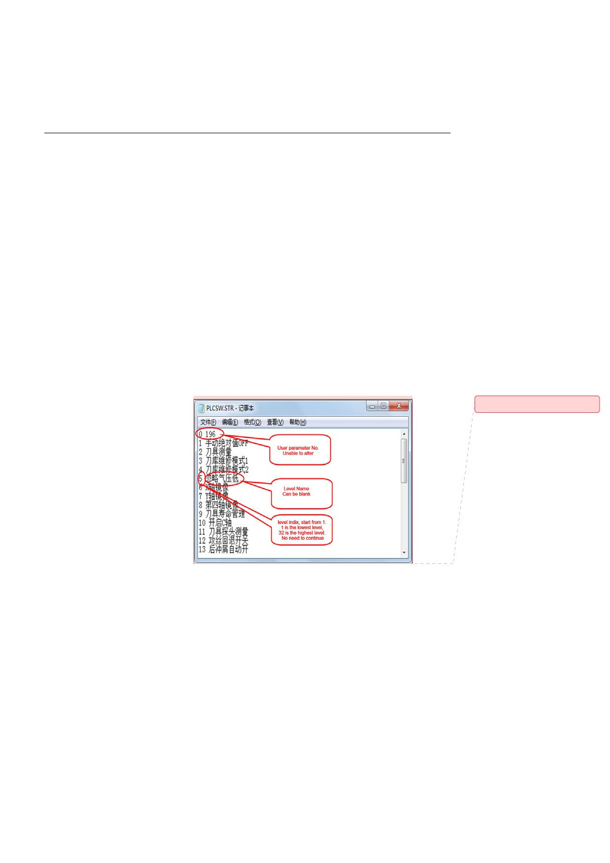
8.4.3 PLC Switch Settings
The PLC switch settings function is used to decode the specified user P
parameter into 32 bits; each bit can be used as a configurable PLC
switch.
You may use the PLCSW.STR configuration file under the parm
directory to conduct the PLC switch settings. The PLCSW.STR file is in
the following format:
批注 [z15]: 中文图
After the PLCSW.STR file is configured, you may press Set → PARA
→ DT MGT to select PLC FILE and import the PLCSW.STR file. See
the figure below:
124