HNC-818. User Manual - page 2
3. Manual Operation
Press the save key to save the input
G code as a program.
32
4. Settings
4 Settings
This chapter describes the data settings of the system, which includes:
Tool Data (T series)
Tool Data (M series)
Coordinate System Settings
RCS Clear
Parameter Settings
33
4. Settings
4.1 Tool Management
4.1.1 Tool Magazine
Operation procedure
1.
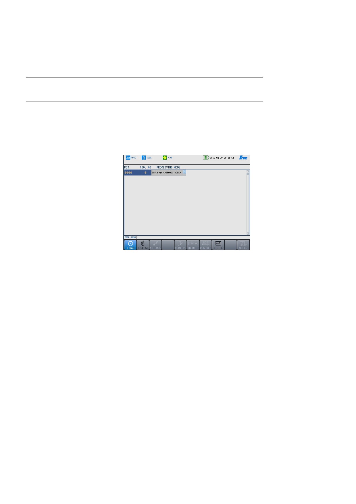
Press Oft →T MAG. The tool magazine data table is displayed,
where the data can be set. See the figure below:
2.
Press ▲ and ▼keys to move the cursor to select the item to be
edited.
3.
Press Enter to enter the editing status.
4.
Press Enter again after modification.
4.1.2 Tool Compensation
Operation procedure
1.
Press the Oft main menu. The tool compensation data table, which
includes tool length, tool radius, length wear and radius wear, is
displayed.
2.
Press ▲ and ▼keys to move the cursor to select the required tool
number.
3.
Press ► and ◄ keys to select the items to edit.
4.
For example, select “length” option and press “current position” key,
the system will automatically input the current position data.
34
4. Settings
5.
Press Enter to enter into the editing status; Press the “incremental
input” key so that the system automatically adds data.
Note: The valid range of data for editing is from -10000.0 to
10000.0.
6.
After editing, press Enter again.
4.1.3 Tool Life Management
See section 4.1.4.
4.1.4 Tool Machining Modes
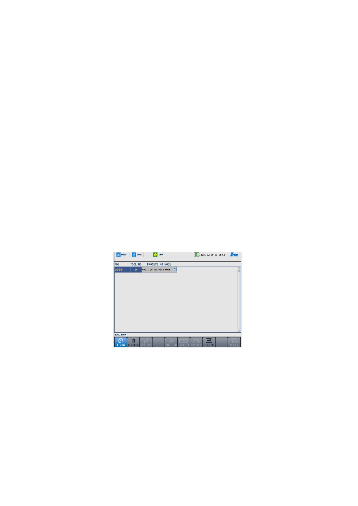
Machining modes corresponding to tool number can be set on the tool
interface. After calling a tool, the system automatically calls the
corresponding tool machining mode, e.g. default mode
(G05.1Q0),
high-precision mode
(G05.1Q1), high-speed high-precision mode
(G05.1Q2), high-speed mode (G05.1Q3). See the figure below:
To use this function, it’s necessary to call G115L3 before all M99
commands in the M06 subprogram of USERDEF.CYC, and enable the
tool machining mode function through 010089 [T command control
mode].
Disable the tool machining mode function through 010089 [T command
control mode] if you do not need to use this function.
4.1.5 Tool Management Based on RFID
35
4. Settings
Power on the reid reader and connect the RS232 communication
interface to the computer.
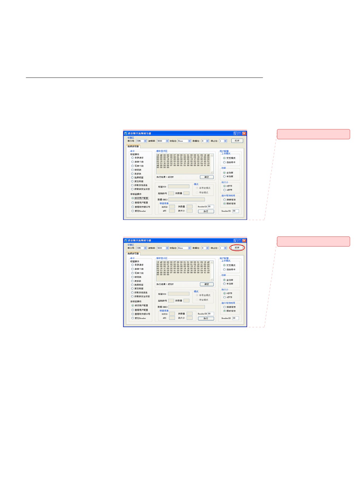
Run the "SYGOL high-frequency digital reader Demo program.exe"
to achieve the read-and-write data transmission of RFID and CNC
tool data. See the figure below:
批注 [z1]: 中文图
y As shown in the figure below, click Open.
批注 [z2]: 中文图
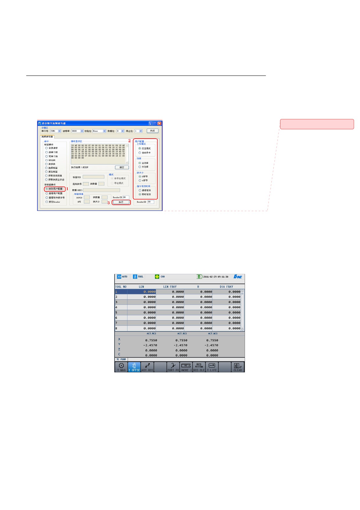
y As shown in the figure below: select Change user configuration
(see 1), configure user information (see 2), and then select Execute
(see 3) to complete the user configuration of the reader.
36
4. Settings
For detailed information, see the relevant commissioning user
manual.
批注 [z3]: 中文图
4.1.6 RCS Clear
Write the Z-axis values in the relative actual coordinates into the
corresponding tool length compensation where the cursor is.
37
4. Settings
38
4. Settings
4.2 Coordinate System Settings
4.2.1 Setting Coordinate System
Follow the instructions below to set the coordinate system:
1.
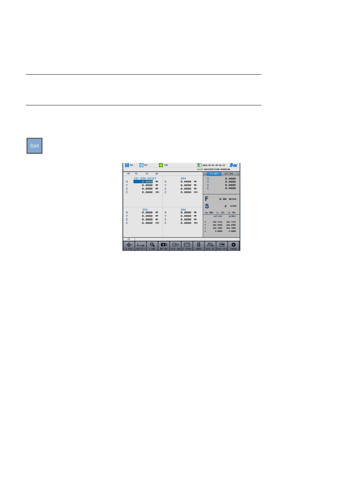
Press the Set menu and enter the manual coordinate system settings
mode. See the figure below:
2.
Press the "PgDn", "PgUp" keys to select the coordinate systems to
be set. E.g. G54, G55, G56, G57, G58, G59, workpiece
(the
coordinate value of workpiece origin relative to the machine origin),
relative (the origin of the current relative value), G54.1-G54.60.
3.
Users may press FIND to search for specific workpiece coordinate
system type. There are two input formats for coordinate system
search:
• "Px" indicates the extended coordinate system x
E.g. P39 indicates to search the G54.39 extended workpiece
coordinate system.
• "x" indicates the coordinate system number
E.g. If 2 is entered, then G55 will be searched.
4.
Enter the position information of the selected coordinate system,
then users may use any of the following methods:
•
Enter the required data in the editing box.
•
Press C. POS, OFFSET, and UNDO to enter data.
39
4. Settings
b.
[OFFSET]: If "+0.001" is entered, the coordinate system
position of the selected axis is the current position plus the
entered data. If "-0.001" is entered, the coordinate system
position of the selected axis is the current position minus the
entered data.
c.
[UNDO]: Restore the last defined value.
• The system reads the current tool position via pressing "WP
MS →Record I" and "WP MS →Record II" ,then it calculates
the midpoint of the two (Record I and Record II) through
pressing "WP MS →Midpoit" and takes the point as the origin
of the coordinate system.
5.
If the entered value is correct, the modified value will be displayed
in the corresponding position; otherwise, the value will not be
changed.
a.
[C. POS]: The system reads
the current tool position.
40

4. Settings
4.3 Clear RCS
Operation procedure
Press Set → RCS CLE to enter the interface as following:
Enter the axis name, e.g. X, the X axis values will be cleared. Meanwhile,
The system coordinate system is changed to the relative coordinate
system. The coordinate value is 0. In this case, the coordinate value is the
relative one based on the current position when the workpiece is
manually moved. When you exit the interface, the coordinate system
restores to the one before entering the relative coordinate system.
41
4. Settings
4.4 Parameter Settings
4.4.1 System Parameters
View parameters types
1.
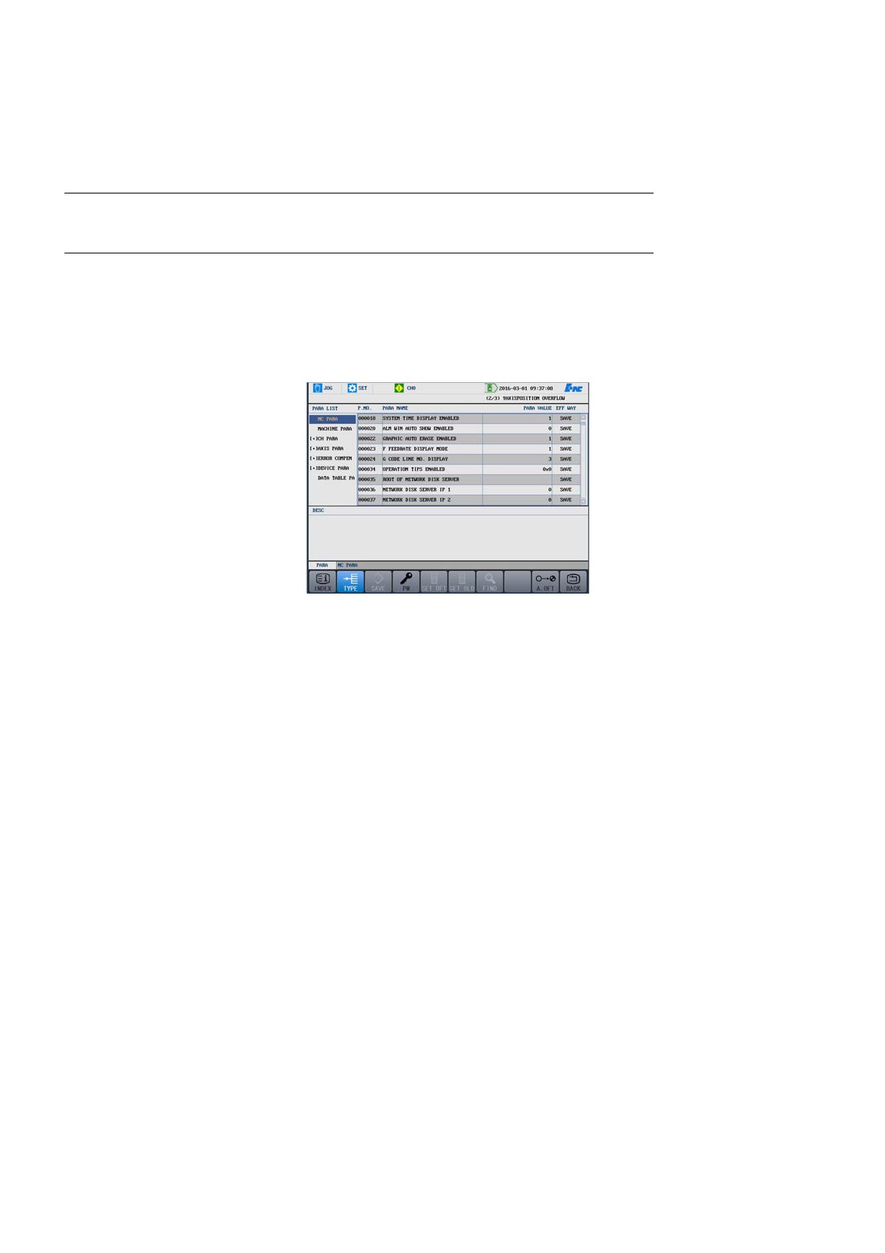
Press Set → PARA → NC PARA to enter the interface shown in
the figure below:
2.
Press ▲ and ▼ keys to select a parameter type as required.
3.
Press ► key to enter the parameter list, select a parameter, and the
detailed information will be displayed in the lower pane of the
screen.
View Parameter Index
1.
Press Set →PARA → NC PARA → Index.
2.
Press
▲ and ▼ keys to select a parameter, and the detailed
information will be displayed in the lower pane of the screen.
Note: See HNC-8 Parameters Description. for details about each
parameter of HNC-818.
Enter password for parameter
1.
Press Set →PARA → NC PARA→ Password.
editing
2.
Enter the password for parameter editing.
3.
Press Enter. If the password is correct, the parameters can be
edited.
If users want to modify the system
parameter values, they need to edit a
password to obtain the permission.
42
4. Settings
Edit Parameters
1.
Enter the correct password for parameter editing.
2.
Select a parameter to be edited according to the index or type , press
Enter to enter the editing status.
3.
Enter a parameter value and press Enter to end the editing.
Save parameters
1.
Press Save after editing all parameters.
2.
Press Y if you want to save the modification.
3.
Press N if you do not want to save the modification.
Note: Some parameters' modification takes effect only after power
off and restarting the system.
Restore the default value
Press the corresponding Default Restore key if you want to restore the
default value of a parameter.
Restore the previous value
After editing a parameter, press the corresponding Previous Value
Restore key if you want to restore the value before editing, .
Note: The operation works only before the parameter value is saved.
Search parameters
In the parameter index viewing mode, press Search, enter the parameter
index number, press Enter, the system will locate the defined parameter.
Device configuration
Use the device configuration navigation function to set the device
number.
1.
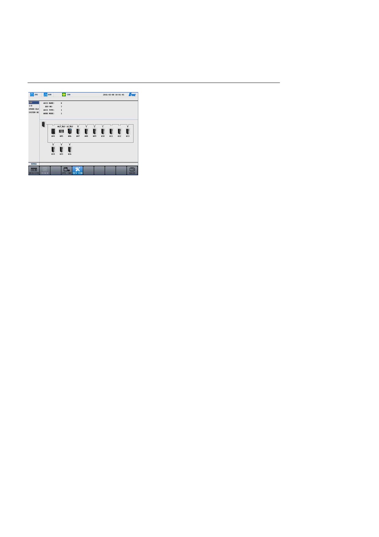
Press Set →PARA → NC PARA → DEV CON. The topology of
the hardware connection is as below:
43
4. Settings
2.
Use the ▲ and ▼ keys to select a device type.
3.
Press Enter. The configured information of the device type
(including axis name, input, output, or other units) is displayed.
4.
Press "Alt+n" and move the cursor to the area on the right of the
screen.
5.
Press ▲ and ▼ keys to select the data type to be edited.
y Channel: axis name, device number, axis type, and operation
mode.
y Input and output: device name, device number, initial group
number, and group count.
y Other units: device name and device number.
6.
Press Enter to edit the selected data type (except for the device
number). If you need to edit the device number, use ▲ and ▼ keys
to move the cursor to select the device in the device configuration
navigation pane and press Enter. The system will automatically
read the device number.
Note: See HNC-8 Parameters Description. for details about each
device.
Automatic offset
1.
Press Set →PARA → NC PARA→ A.OFT.
2.
Enter the logic axis number.
3.
Press Enter, and then the system automatically calculates and
enters the encoder feedback offset of the corresponding axis
parameter.
4.
Press the Save key to save the modification.
4.4.2 Parameters Display
Operation procedure
44
4. Settings
Set the information displayed in the
large character area and small
character area.
• Display column 2: set the value of the second column in the
1.
Press Set
→PARA→ Display
large character area
Parameters.
• Display column 3: Set the value displayed on the tab
2.
Use
▲ and
▼ keys for
selection.
3.
Use ► key to move the cursor to the parameter list.
• Display column 1: set the
4.
Use ▲ and ▼ keys to select the type to be displayed.
value of the first column in
5.
Press Enter.
the large character area
Note: You may use ► and◄ keys to switch the value displayed on the
tab.
4.4.3 Graphic Settings of User P Parameters
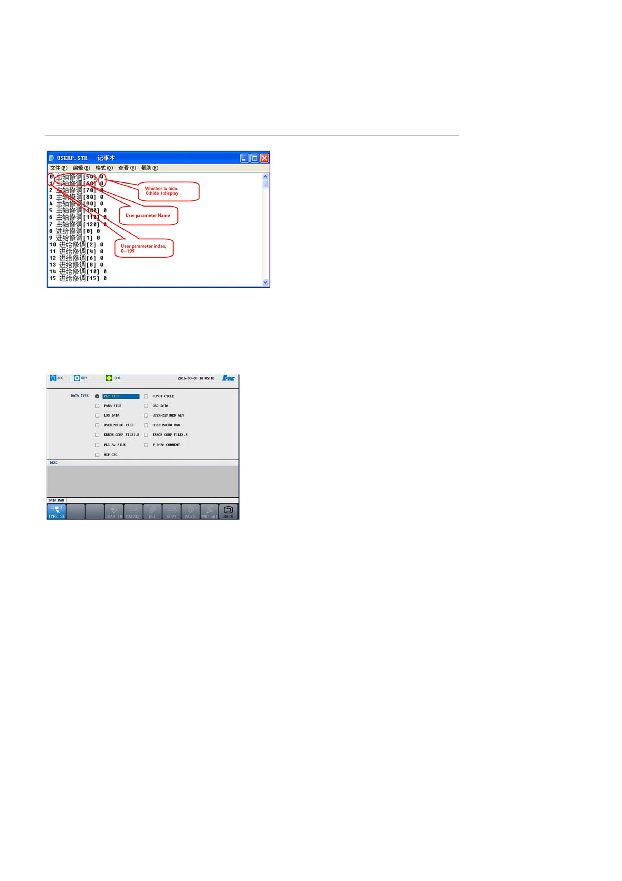
The settings of P parameters require the USERP.STR configuration file
under the parm directory. The format of the file is as below:
45
4. Settings
Press Set → PARA → DATA MAN
and select PLC FILE to import the
created USERP.STR configuration
file into the CNC system. See the
figure below:
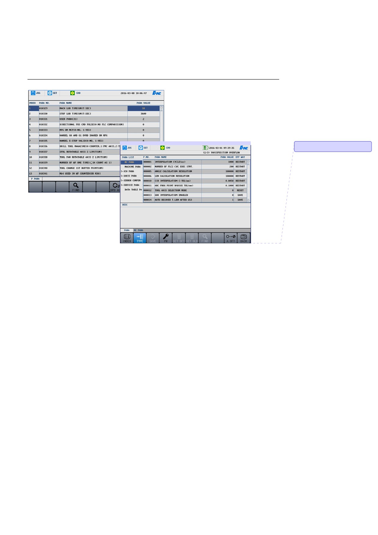
This function is used to set the values of the user parameters
(010300 to 010499). See the figure below:
46
4. Settings
FIND: move the cursor to the specified line through index number.
UPD ALT: save the configuration to the parameter file.
UNDO: recover to the initial parameter value.
The result of P parameter setting can also be got through modification of
the machine parameters (see Chapter 4.4.1). See the figure below:
批注 [A4]: 对应图有误
Operations on the interface:
Only the machine manufacturer or
above can set it.
Up, Down, Left, Right keys: to move
the position of the cursor.
Enter: Set the parameter value where
the cursor is.
Operations on the menu:
4.4.4 Parameter Update after System Upgrade
47
4. Settings
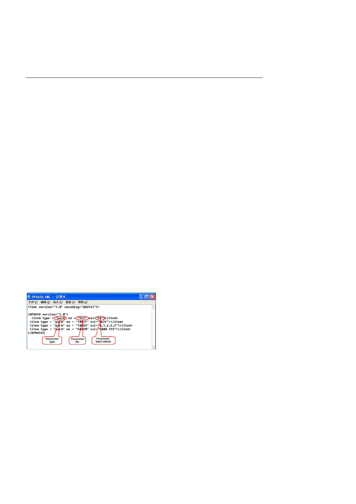
parameter value to be input.
Note:
1.
After the UPDATA.XML file is successfully read, it will be deleted.
Therefore, this function takes effect only once.
2.
After the parameters are updated from the UPDATA.XML file, the
system will save and load the parameters again.
If some new parameters are added
3.
The UPDATA.XML file is released with the software upgrade
after system version upgrade, the
package. Just place it into the data directory of the upgrade package.
new parameters value should be
manually defined. Hence, the
function is used to automatically
update the new parameters values.
Write the parameter values that need
to
be
defined
into
the
UPDATA.XML file, and then place
it into the system upgrade package.
During the system upgrade, the
UPDATA.XML file will also be
updated to the CNC system. When
CNC starts, the system will detect
and read the information in the
UPDATA.XML file. The parameter
values will be automatically reset .
UPDATA.XML file format:
Parameter Type: fixed as "parm".
Items without it cannot be identified
by the system.
Parameter Number: the number of
the parameter requires automatic
update.
Parameter Input Value: the
48
4. Settings
4.4.5 Parameter Configuration Interface
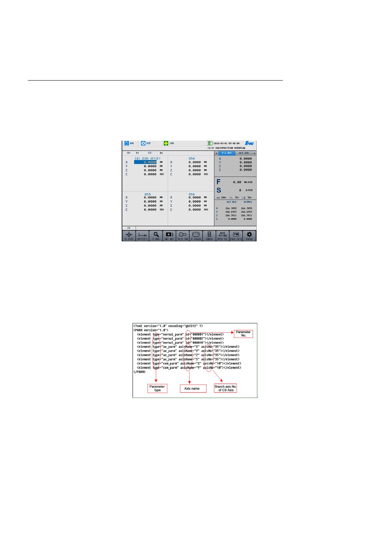
This function is used to manage parameters as required. See the figure
below:
Operation description
1.
XML file configuration: Users and machine debugging personnel
configure the xml. parameter files which maintain their own
parameter lists. The
.xml file for users is named as
CFG_PARM_U.XML which can save up to
50 parameters.
The
.xml file for debugging personnel is named as
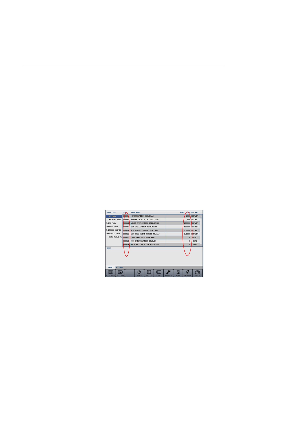
CFG_PARM_D.XML which can save up to 200 parameters. Both
are placed in the data directory. See the figure below:
a) For non-axis and non-compensation parameters (normal_parm),
directly enter the parameter ID (id).
49
4. Settings
b) For axis parameters (ax_parm), the axis name (axisName) and
axis number (axisNo) should to be provided, The axis name
must be within {x, y, z, a, b, c, u, v, w, s} and is case
insensitive. The system will find the corresponding logical axis
number and branch axis number based on the given axis name,
and then determine the axis parameter ID.
c) For the compensation parameters (com_parm), the method to
determine the parameter ID is similar as that of the axis
parameters.
d) Device parameters and data table parameters cannot be written
in the .xml file as configurable parameters.
2.
The two types of configured .xml files can be displayed on the
parameter configuration interface. The user .xml file is displayed by
default. Debugging .xml file can be displayed after the debugging
personnel enters correct password. After entering the parameter
configuration interface, the parameters can be modified and saved .
If the system prompts you that there is no permission to modify the
file, you may enter the corresponding password and then modify the
parameters. See the figure below:
4.4.6 Time
Operation procedure
If you select to display the system time in the machine parameters, you
may use the function to reset the system time.
1.
Press Set → PARA → TIME to enter the system time settings
mode.
2.
Use the cursor to select the time.
50

4. Settings
3.
Press Enter to enter the editing status, where users may input data.
4.
Press Enter again to save the settings.
4.4.7 Batch Debugging
exported in batches.
1.
Press Set → PARA → ALL.
2.
By default, the system will select all data types. Press Enter to
cancel some data types.
3.
Press WD SW, then the cursor moves to the file directory area,
where USB flask disk or CF card can be selected.
4.
Press BACKUP, and the message whether you back up the file of
the selected data type is displayed. Press Y and the system prompts
successful backup.
5.
Users may press LOAD to load files as required.
Debugging Files can be importd or
Attention
The function is avialabel to machine users, CNC manufacturers
and administrator.
1.
If you back up the file to the CF card, the system will automatically
name the file as fileman_backup.tar.
2.
If you back up the file to the USB flask disk, the system will
automatically name the file as
fileman_backup_YYMMDDTIME.tar.
51
4. Settings
3.
Power off is not allowed during
backup.
52
4. Settings
4.4.8 Data Management
The function is used to load/back up parameters, PLC, fixed cycle, logs,
compensation, and oscilloscope files.
Note 1: This section takes system parameter files to describe the
loading/backing up operation procedure. Other files (except for error
compensation files) follow the similar operations.
Note 2: Power off is not allowed during back up.
Note 3: This function is available only to machine users, CNC users
and administrator.
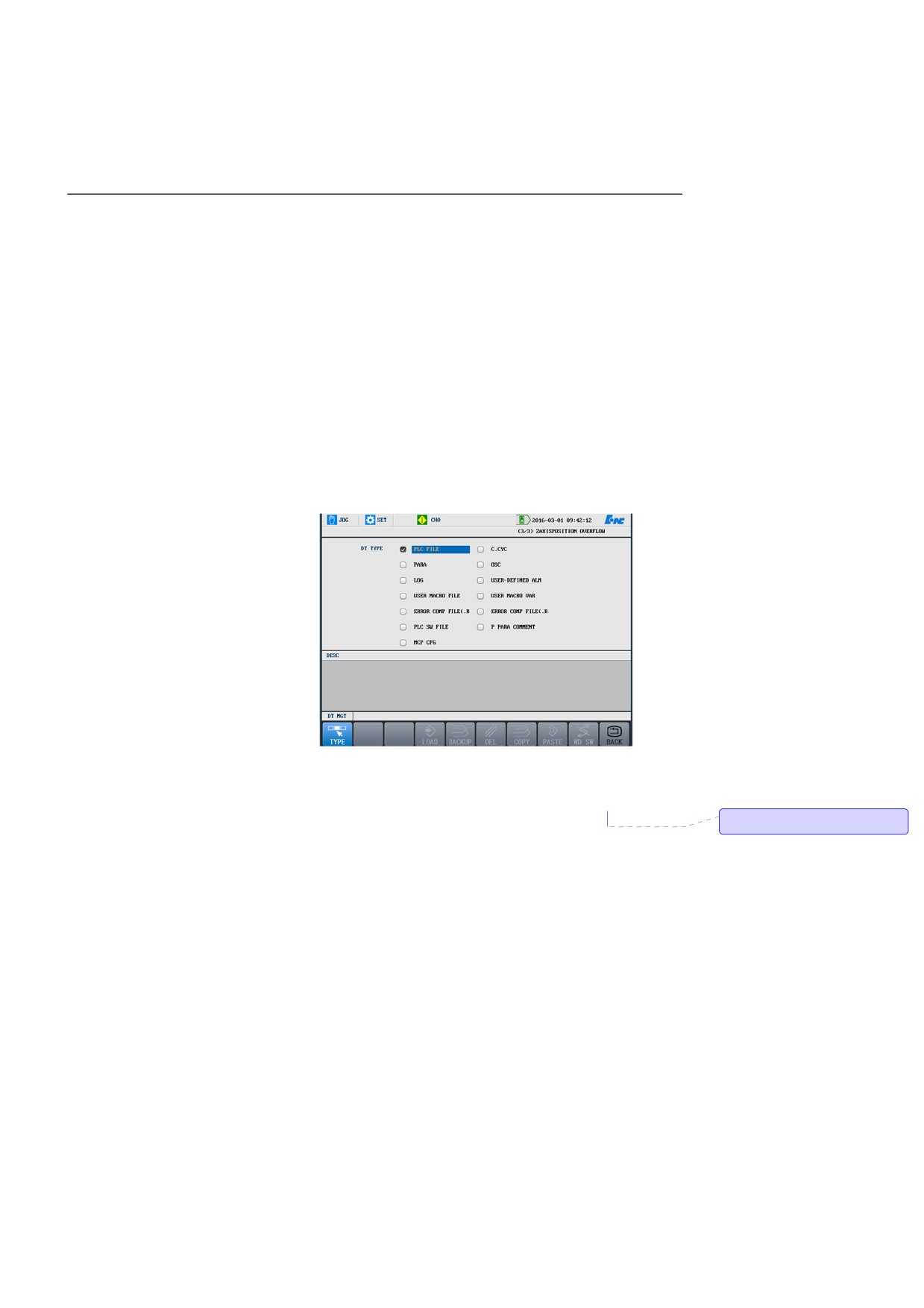
1.
Press Set → PARA → DT MGT.
2.
Move the cursor to select the data type to be imported or backed up,
press Enter.
3.
Move the cursor to select the file to import or back up.
批注 [A5]: 原文重复,删否
4.
Press WD SW, and move the cursor to the file path where the files
will be imported or backed up.
5.
Press Enter or BACKUP again.
6.
Press COPY and PASTE to copy and paste the files.
53
4. Settings
Error
compensation
file
HNC-8 series supports automatic import of pitch error file generated by
import/backup
Renishaw laser interferometer.
1.
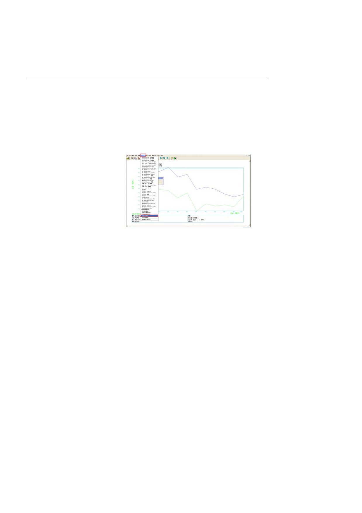
Generate pitch error file LEC.REN.
Open the *.rtl file generated by Renishaw laser interferometer,
select Analyze Data from the menus, select Error Compensation
Chart from the drop-down list box, and set parameters in the dialog
box that appears.
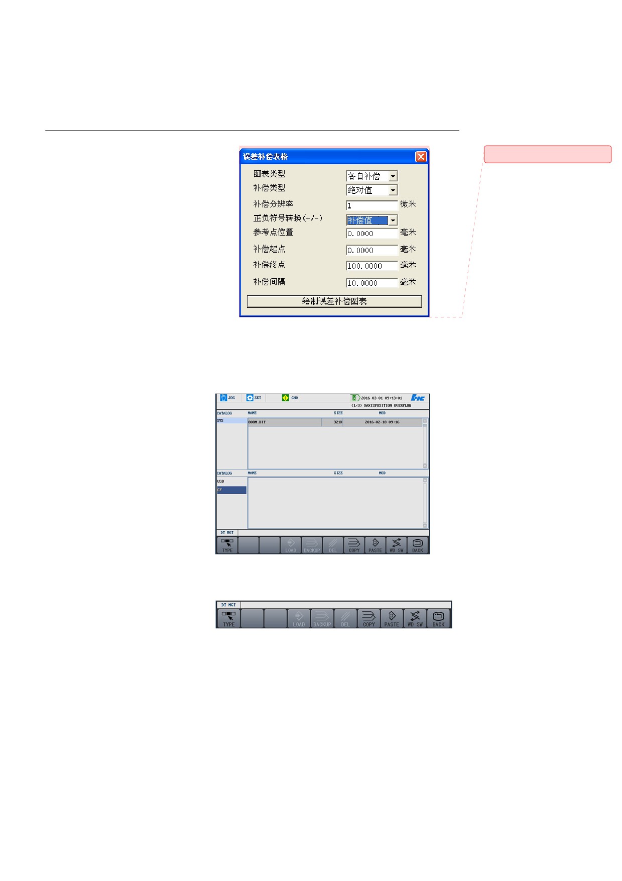
2.
Conduct settings as following instructions:
a. Set Chart Type as Individual Compensation.
b. Set Compensation Type as Absolute Value.
c. Set Compensation Resolution as 1 micrometer or 0.001
millimeter.
d. Set Positive and Negative Symbol Change (+/-) as Error
Value or Compensation Value.
e. Set Reference Position as 0.
f.
Set Compensation Start Point as the position of compensation
start point.
g. Set Compensation End Point as the position of compensation
end point. The start point must be less than the end point.
h. Set Compensation Interval as compensation interval, which
must be a positive value.
i.
Click "Draw Error Compensation Chart" to generate the
LEC.REN file. It is a temporary file which is saved in the
installation directory of the Rainshaw software (generally
C:\Program Files\Renishaw LaserXL). Copy the LEC.REN file
to the USB flask disk.
54
4. Settings
批注 [z6]: 中文图
3.
Press Set → PARA → DT MGT, select Error Compensation File,
and press Enter.
4.
Press WD SW, select USB flash disk or CF card, select the
LEC.REN file, and press Import.
5.
Enter the axis number where the pitch error data will be imported,
and press Enter to import the data.
6.
Press Set → PARA→ NC PARA →ERROR COMPEN, press
Enter to expand the compensation parameter table to view the
corresponding pitch error compensation parameters. For example,
Compensation axis 0—300020, 300021, 300022, 300023, and
300026 are all configured.
55
4. Settings
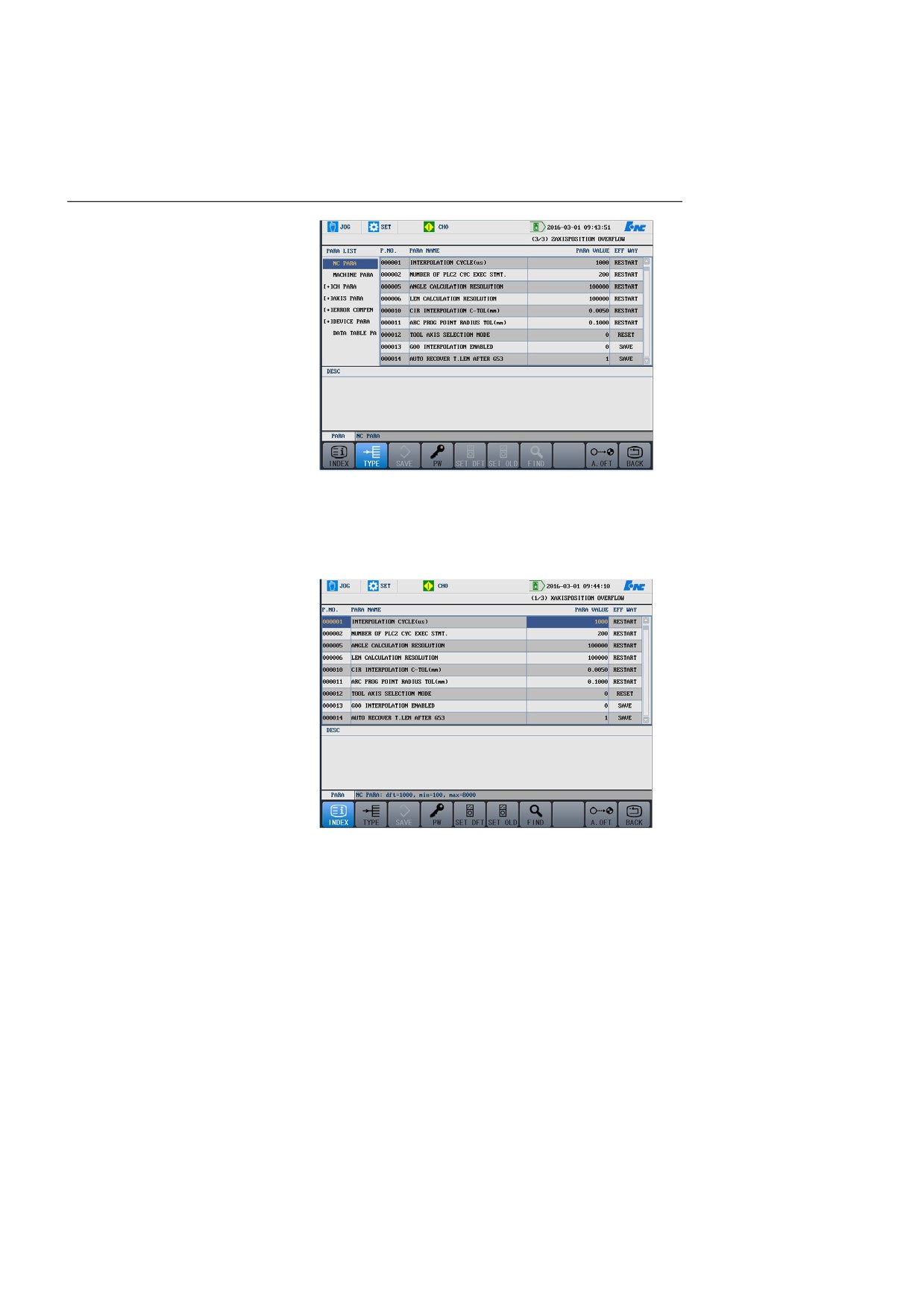
7.
Press Set → PARA→ NC PARA → DATA TABLE PARA to view
corresponding parameters. (The compensation values in the pitch
error compensation file .REN are written to the data table
parameters of (710000+ axis number*1000)).
- Rules for unidirectional pitch compensation data table:
negative return to zero, then write the compensation value of
"Positive Machine Movement" into the data table started with
(710000+ axis number * 1000) in the positive sequence;
otherwise, write the compensation value of "Negative Machine
Movement" into the data table started with (710000+ axis
number * 1000) in the positive sequence.
- Rules for bidirectional pitch compensation data table:
negative return to zero, then write the compensation value of
"Positive Machine Movement" into the data table started with
(710000+ axis number * 1000) in the positive sequence, and
56
4. Settings
then write the compensation value of "Negative Machine
Movement" into the data table in the positive sequence.
Otherwise, write the compensation value of "Positive Machine
Movement" into the data table started with (710000+ axis
number * 1000) in the positive sequence, and then write the
compensation value of "Negative Machine Movement" into the
data table in the positive sequence (For positive return to zero,
all input data should be minus the last value in the "Negative
Machine Movement" column).
4.4.9 Permission Management
After installing and testing the system, it’s unnecessary to modify the
parameters. If you need to modify certain parameters, select the
appropriate user level and enter the correct password for modification.
The password itself can also be modified, provided that you enter the
correct password.
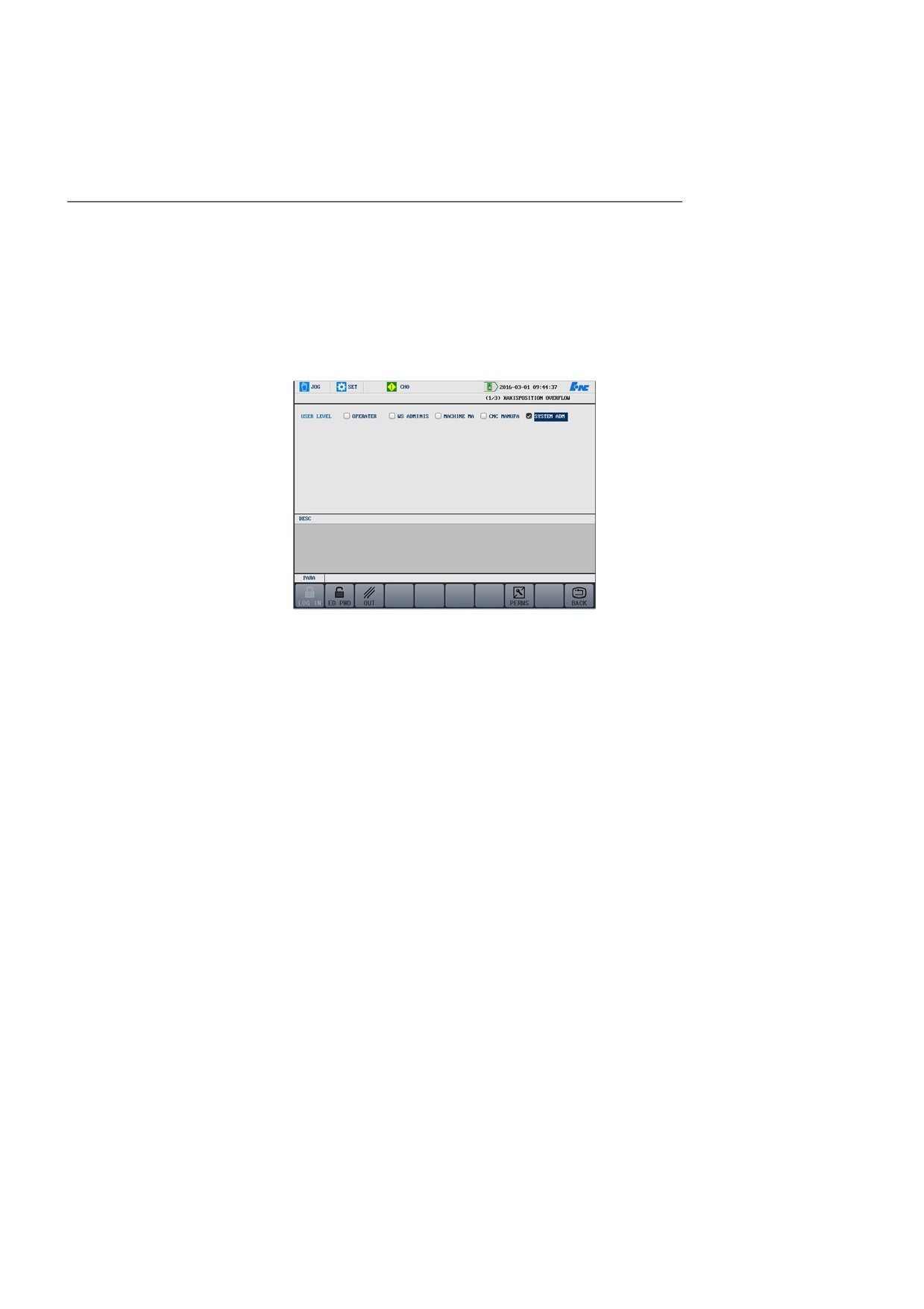
User level
Parameter configuration has significant effects on the system
performance, so the system parameter modification is strictly limited.
User permissions of this system can be divided into four categories:
operator, workshop administrator, machine manufacturer, CNC
manufacturer, and system administrator.
"OPERATOR" permission indicates no permission. When other
permissions are canceled, the system will automatically change the
permissions to the OPERATOR permission. The 000359 parameter can
be used to set the default permission after the system boots. If the
parameter is set to 0, the default permission is WS ADMINS; if the
parameter is set to 1, the default permission is OPERATOR.
User Logoff
Press Set → PARA → PERM MGT → OUT, a user type can be
reselected.
Enter password
1.
Press Set → PARA → PERM MGT.
57
4. Settings
2.
Select a corresponding user’s
type, and press LOG IN.
3.
Enter the password, and press Enter.
4.
If the permission password is correct, the parameters and password
of the corresponding level can be modified. Otherwise, the system
will prompt that the password is incorrect.
Modify password
1.
After entering correct permission password, press the ED PWD
key.
2.
Enter the new password in the editing box, and press Enter.
3.
Enter the same password again, and press Enter again.
4.
After thant, the password is successfully changed.
4.4.10 Permission Configuration
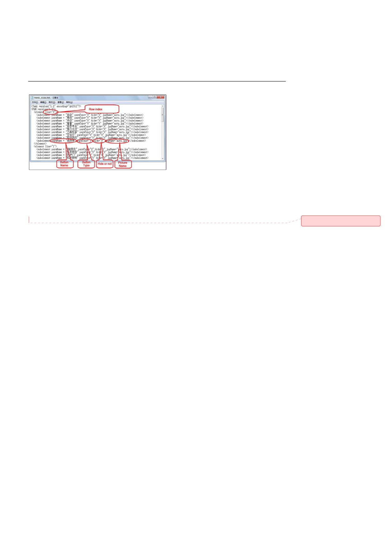
Permission configuration file
The default permission configuration file is the PANEL_818A.XML file
in the bin directory, which can configure the permission of all user levels.
Its format is as below:
58
4. Settings
Line: Line index (0-6), which can be discontinuous. It’s unchangeable
that “line= 6” is used for interface menu configuration.
paraName: Key name, up to 4 Chinese characters.
ParaType: Key type. The value 0 indicates text while 1 indicates picture.
批注 [z7]: 中文图
Hide: Set whether to hide or display. The value 0 indicates to display
while 1 indicates to hide.
jpgName: Key picture name, valid only when ParaType is 1.
The quantity of sub-element in each element group cannot exceed 10.
59
4. Settings
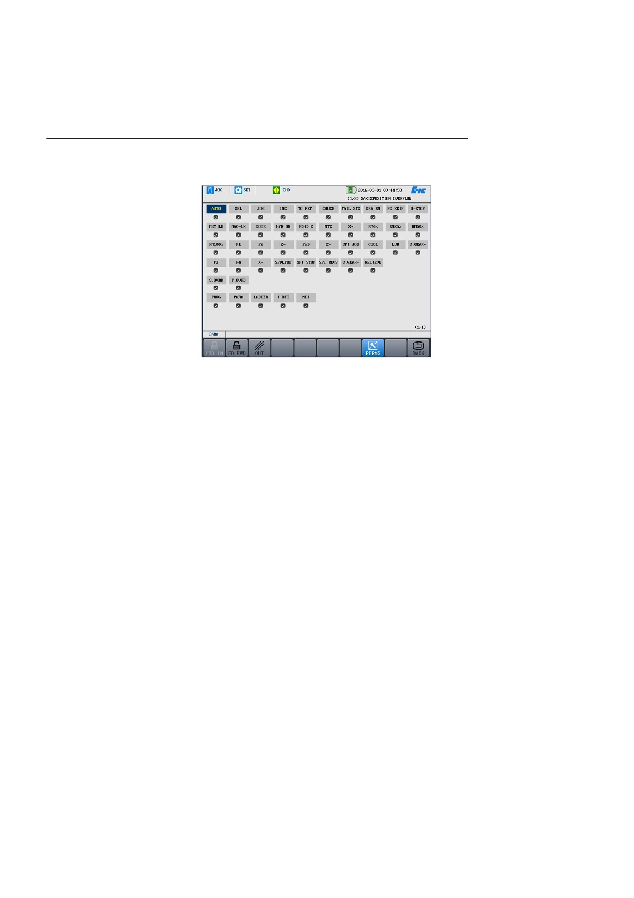
Operations on permission
With the permission configuration file, you may configure the operation
configuration
permission for all levels through the PERMS menu.
The general principle is that the user with higher permission can
configure the permission for the users with relatively lower permission.
Operations on interface
Up, Down, Left, Right keys: to move the position of the cursor.
Enter: define the value of the position where the cursor is. If the current
status is ON, set it to OFF; if the current status is OFF, then set it to
ON.
The settings will be saved in the NC parameters (360 to 377).
The configuration for users with different permissions are separately
saved. What is modified is effective to theusers with subordinate
permissions, but ineffective to the users with the same permissions.
The configuration with different permission is saved as follows:
y NC parameter 360-362: current configuration
y NC parameter 363-365: users
y NC parameter 366-368: machine manufacturer
y NC parameter 369-371: CNC
y NC parameter 372-374: administrator
y NC parameter 375-377: reserved
60
4. Settings
Change user permission with
In addition to the permission management function, you may quickly
external PLC
change the user permission through external I/O signal, e.g. user
permission configuration key.
The method is to write value into the G2979 register.
y Value 0: operator permission
y Value 1: workshop manager permission
y Value 2: machine manufacturer permission
y Value 3: CNC manufacturer permission
y Value 4: system administrator permission
After permission modification, a customized 121 event should be sent in
order to inform the system that the permission has been changed.
Switch permission between
In the actual production process, the workshop operator can only repeat
OPERATOR and WS ADMINIS
the fixed cycle operation, and has no right to modify the program or feed
by using the key lock mode
override. The workshop administrator has right to modify the program or
tool compensation. On site, use the key lock mode to switch between the
two kinds of permission in order to ensure normal operation. The
following is a PLC programming example: X486.6 is the key lock input
point.
4.4.11 Network Transmission
Note: The network connection is disabled by default. Set the
parameter [000050] to enable it.
There are two network transmission modes:
1.
Network shares: Access files through the Windows system network
sharing.
Note: The prerequisite is that the administrator user exists in the
Windows system and the password is blank.
61
4. Settings
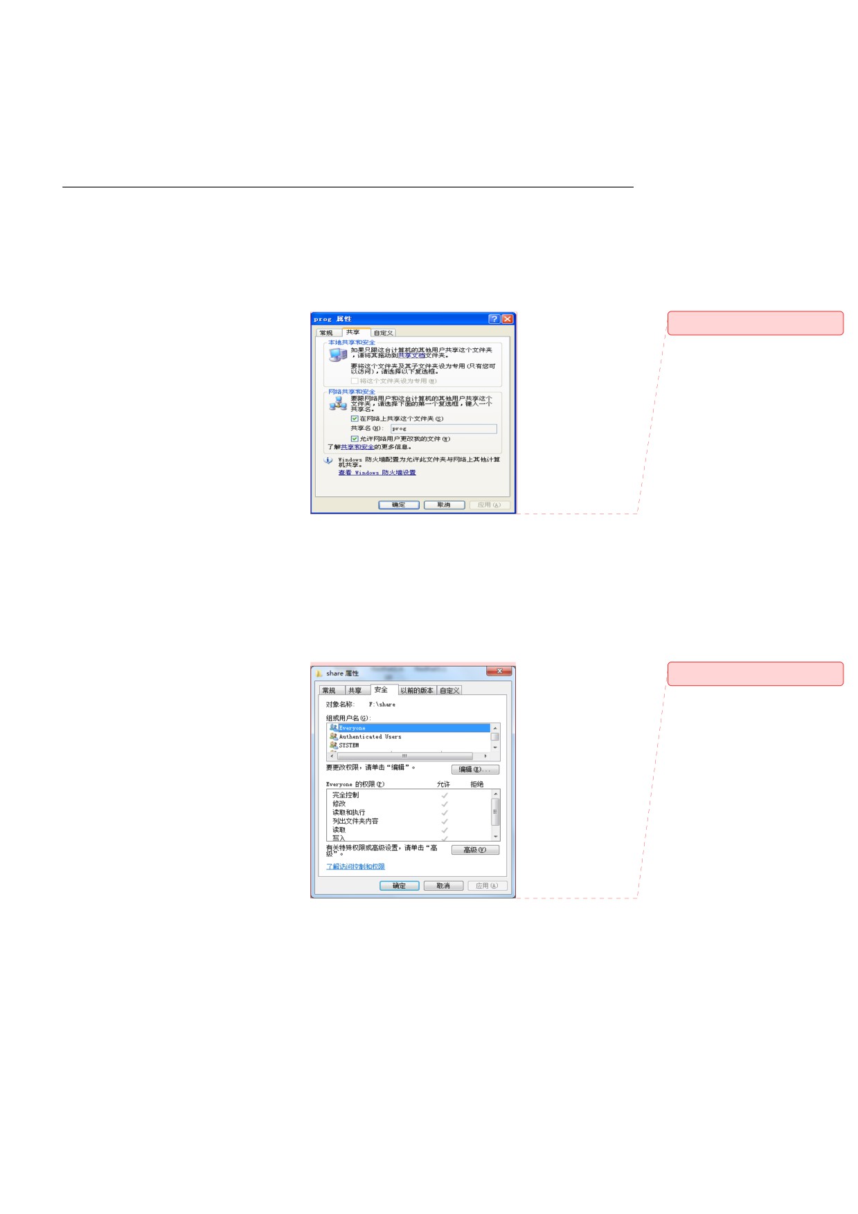
a) Set shared folder in the
Windows
-
Set shared folder in
Windows
XP
operating system
Right-click the folder,
批注 [z8]: 中文图
select Properties, click
Sharing., Select Share
this folder, set Share
name, select Allow for
Change, click Apply,
and then click OK.
-
Set shared folder in Windows 7 operating system
Right-click the folder, select Properties, click Security, click
Edit, click Add to add the Everyone object type under Group
or user name, and then select Full Control under Allow for
Permission for Everyone.
批注 [z9]: 中文图
Right click the folder, select Properties, click Sharing, and click
Network and Sharing Center. On the following page, select
Turn on network discovery and Turn off password protected
sharing.
62