HNC-818. User Manual - page 3
4. Settings
批注 [z10]: 中文图
批注 [z11]: 中文图
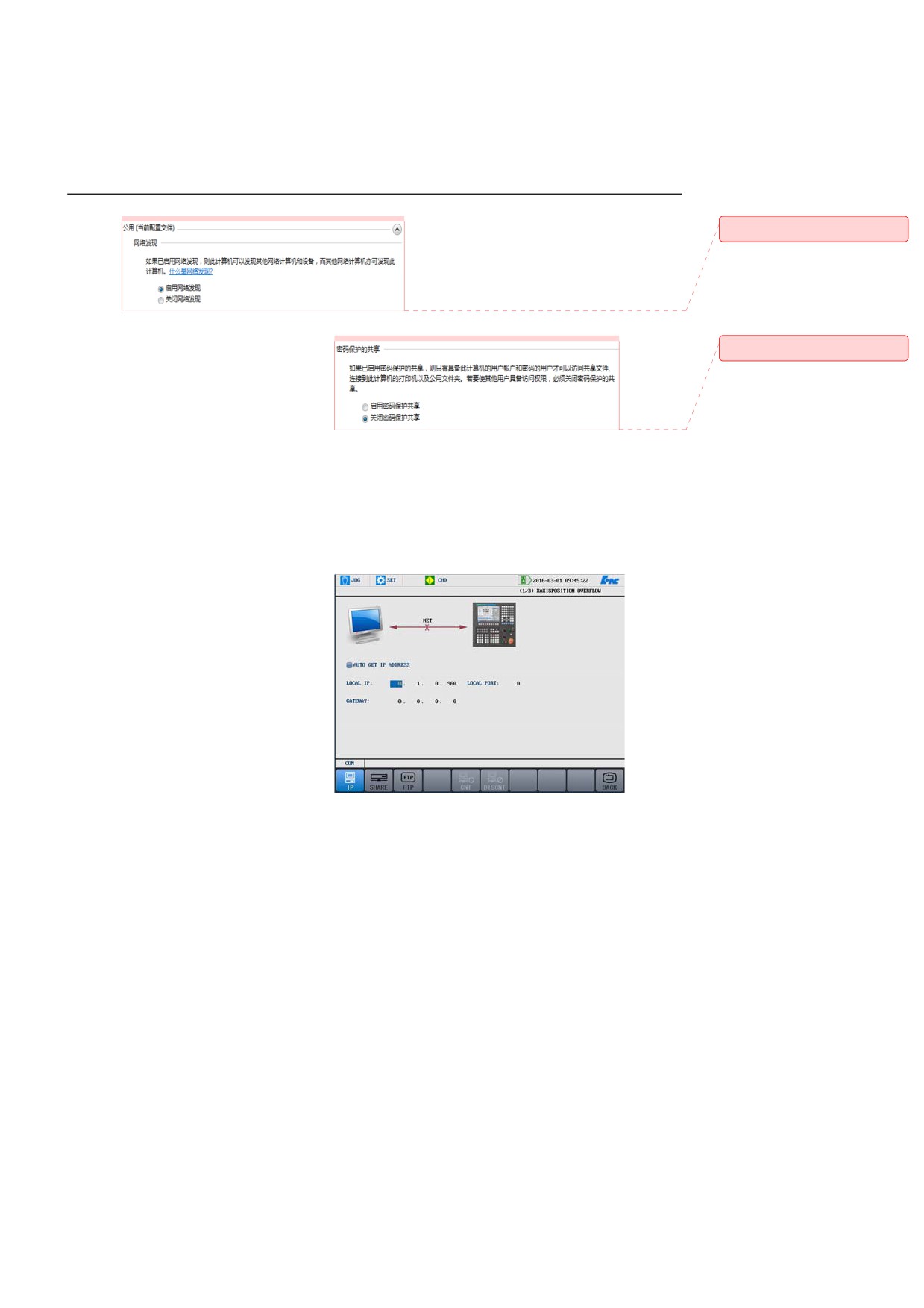
b) Press Set → PARA → COM, and move the cursor to select a
network disk mapping type.
c) Press Enter, and select shared disk.
Note: It is not supported to copy and paste files to the shared disk
through network sharing.
d) Move the cursor to the server IP address, press Enter, and enter
the IP address of the PC where the shared folder is.
e) Move the cursor to the IP address of the local PC, press Enter,
and then enter the IP address of the current CNC system.
f)
Move the cursor to the server root directory, press Enter, and
enter the shared folder name on the PC.
g) Click Network Connection, and the system prompts that the
network has been connected.
h) File download: Program → Select → NET → Right arrow key
→ Copy → Left arrow key → CF card/USB flash disk
/System disk → Paste. Message: Paste success. The file is
successfully downloaded.
63
4. Settings
Note: The sharing disk
does not support file
upload.
2.
FTP server (CNC system as a
client): You need to install a
third-party software as the
FTP server.
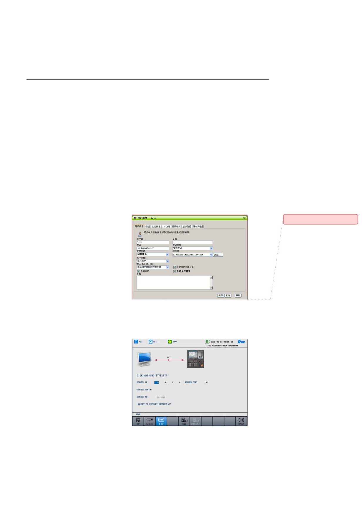
a) Install SERVER-U (V7.3.0.0) on the server. Refer to the official
user manual of SERVER-U for detailed settings. As shown in the
figure below, on the user information tab page, enter the user
name and the password which must be the same with the login
password of the server. Set the Root Directory to the path of the
file to be uploaded or downloaded, and then click the Directory
Access tab page.
批注 [z12]: 中文图
b) Press Set
→ PARA → COM, move the cursor to select a
network disk mapping type.
c) Press Enter, and the select FTP.
64
4. Settings
d) Move the cursor to the
server IP address, press
Enter, and enter the IP
address of the PC where
serve-u is installed.
e) Move the cursor to the
server port, press Enter,
and enter 21.
conflict with other IP addresses of the LAN.
f)
Move the cursor to the
g) The username, password, and root directory name of the server is
IP address of the local
the user information on serve-u.
PC, press Enter, and
h) Press Network Connection, and then the system prompts you
enter the IP address of
that the network is connected.
the CNC system, which
cannot
i)
File download: Program → Select → NET → Right arrow key
→ Copy → Left arrow key
→ CF card/USB flash
disk/System disk → Paste. Message: Paste success. The file is
successfully downloaded.
j)
File upload: CF card/USB flash disk → Right arrow key →
Copy → NET → Paste. Message: Paste success. The file is
successfully uploaded.
4.4.12 System Update
Attention
manufacturer and administrator.
2.
There may be risks in the update. Please back up all machine PLC
files, parameter files, alarms, text, cycle programs and other
documents before the system update.
3.
After the upgrade, the operations on breakpoint must follow the
instructions below:
a) Do not use the breakpoint file which is generated before the
update.
b) It is recommended to conduct update after the machining. If
you use the breakpoint file generated before the update, it may
cause problems such as system crash.
4.
Power off is not allowed during the update.
1.
This function is limited to CNC
65
4. Settings
Operation procedure
1.
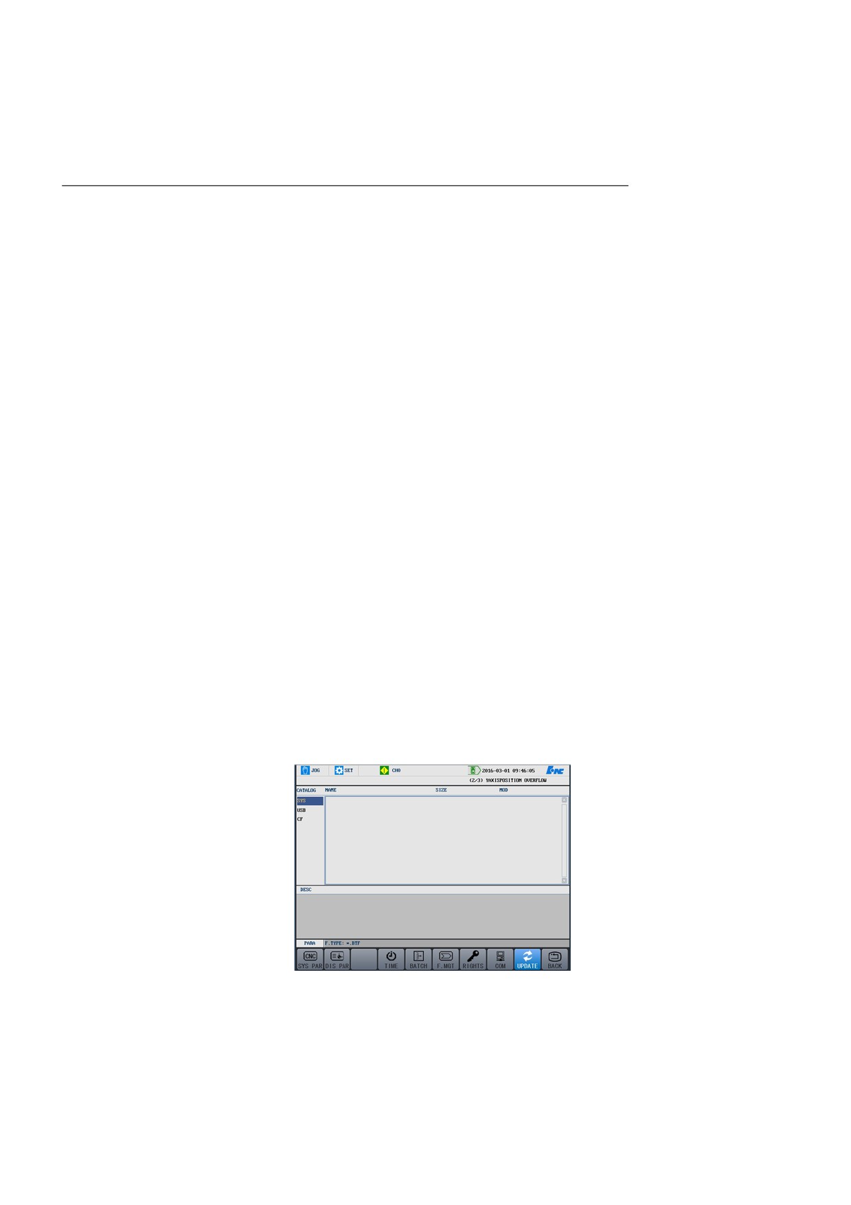
Press Set
→ PARA
→
UPDATE to enter the system
update interface.
Note:
1: Ppress Alt+C and Alt+V to copy and paste information.
2:You can press DEL to delete BTF package only in the CF card
directory.
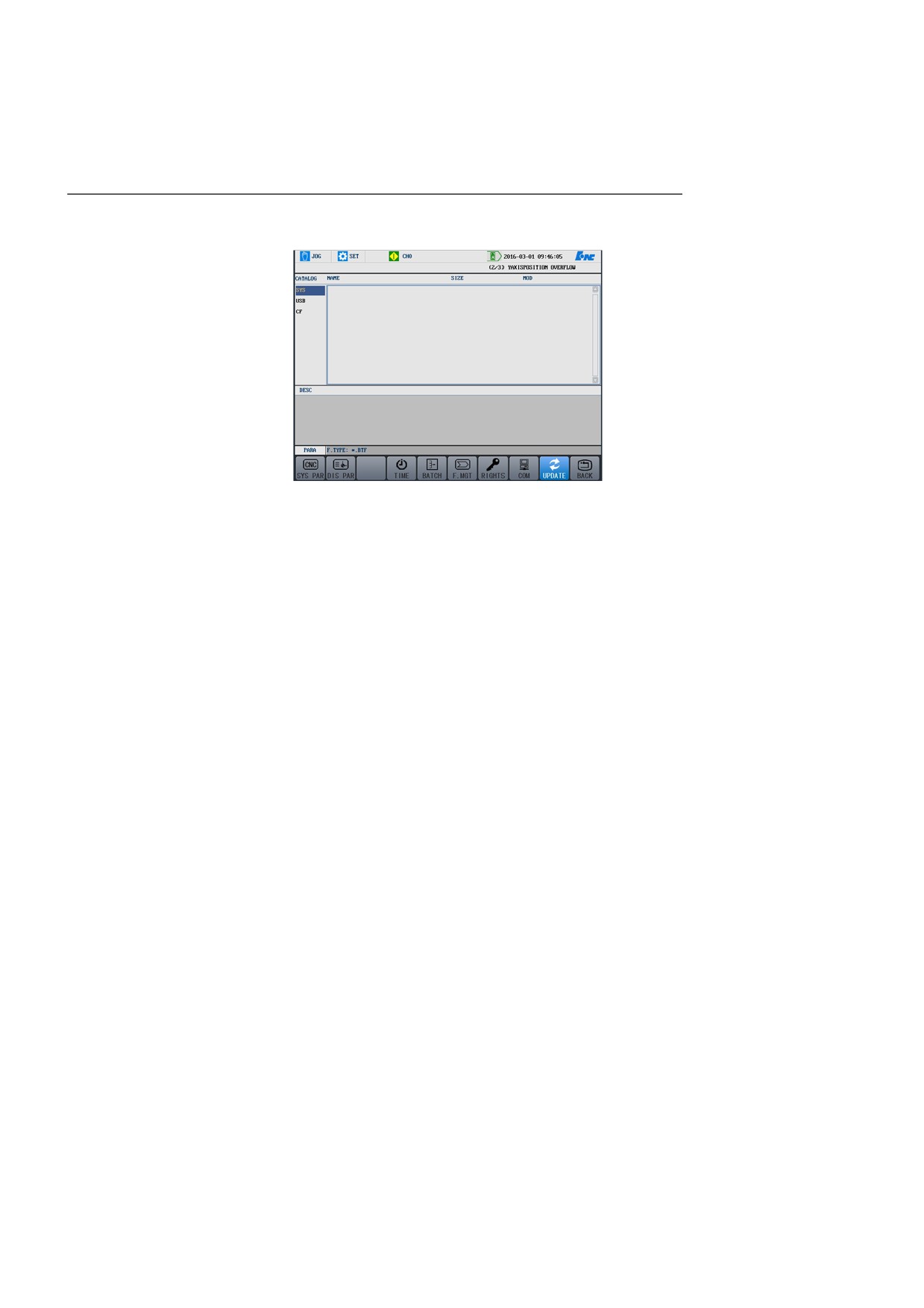
2.
Move the cursor to select the file to be updated, and press Enter to
enter the interface shown in the figure below:
Note: Parameter update can be ONLY used by the debugging
66
4. Settings
personnel. After the parameter
structure file is changed, the
debugging
personnel
can
conduct the parameter update.
3.
Use the cursor to select an
update type and conduct system
backup.
Note: The default directory for
backup is the CF card
directory.
4.
Successively press Yand Enter
to confirm the update, or N and
Enter to cancel the update.
67
5. Program Editing and Management
5 Program Editing and Management
Under the program menu, you may edit, save programs and beyond. The
chapter include the following sections:
• Select Programs
• Edit Programs
• Program Management
• Random line
• Verify Programs
• Stop Running
• Restart Program
• Craft File
• Workpiece Measurement
68
5. Program Editing and Management
5.1 Select Programs
5.1.1 Select a File
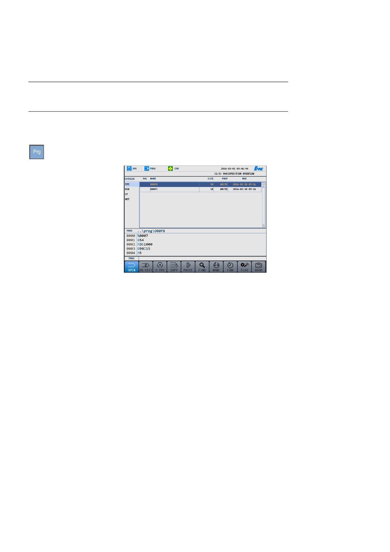
Under the Prog menu, press OPEN to enter the interface as shown in the
figure below:
Follow the instruction below to select a program file:
1.
Press▲ and ▼ to select a storage type (system disk, USB flash disk,
or CF card), and press Enter to view the sub directories under the
storage.
2.
Press ► key to move to the program file list.
3.
Press ▲ and ▼ keys to select a program file as required.
4.
Press Enter to select the file and add it to the machining buffer.
5.
If the selected program file is read-only G code file, the [R] label is
displayed.
Attention
1.
If users select no program file, the system selects the machining
program that is saved in the buffer last time.
2.
The program file name generally starts with O (by default), followed
by four (or more) numbers or letters.
3.
The program file name supported by NNC-818 system is in the "8 + 3"
format: the name consists of one to eight letters or numbers, plus the
extension of 0-3 letters or numbers, e.g."MyPart.001", "O1234".
69
5. Program Editing and Management
Loading and unloading of USB
1.
Use the cursor to select “USB” in “Catalog”..
flash disk
2.
Press Enter to load the USB flash disk.
3.
Press DEL to unload the USB flash disk.
Attention
Unplug the USB after unload it.
5.1.2 Background Editing
Background editing
Background editing indicates that other program files can be edited while
the system is conducting machining.
1.
Select a program by following the instructions in section 5.1.1.
2.
Press
“BG EDIT” to enter the editing status. For detailed
information about editing a program, see section 5.2.
Background Creation
Background creation indicates that a new file can be created while the
system is conducting machining.
1.
Press Prg → OPEN → BG EDIT → NEW.
2.
Enter the file name.
3.
Press Enter to create a file.
5.1.3 Fixed Cycle
Operation procedure
1.
Press Prg → OPEN → C.CYC, and the system displays the fixed
cycle files.
2.
Use the cursor keys to select a file as required.
3.
Press Enter to load the file.
Attention
This function is available only to the machine manufacturer, CNC
manufacturer, and administrator.
5.1.4 Copy and Paste Files
70
5. Program Editing and Management
You may copy and paste a file to a specified path.
1.
Press Prog → OPEN, and select a file to copy.
Operation procedure
2.
You may press FLAG to select multiple files.
3.
Press the PASTE key.
4.
Select a target folder (This cannot be the same folder where the file
is selected.)
5.
Press PASTE to paste the file.
5.1.5 Search Files
Operation procedure
You may search files based on the entered file name.
1.
Press Prog → OPEN → FIND.
2.
Enter the file name, and press Enter. The searched file will be
highlighted.
5.1.6 Sort Files
Operation procedure
You may sort files by time/name.
1.
Press Prog → OPEN → NAME to sort files by file name.
2.
Press Prog → OPEN → TIME to sort files by time.
5.1.7 Encryption for G Codes
Operation procedure
1.
Press Set
→ PARA → NC PARA → TYPE → MACHINE
PARA.
2.
Move the cursor to select parameter 010299—G code file key, press
Enter, and enter the G code file key.
3.
Press Enter again to confirm the operation.
4.
Press Save and restart the system.
71
5. Program Editing and Management
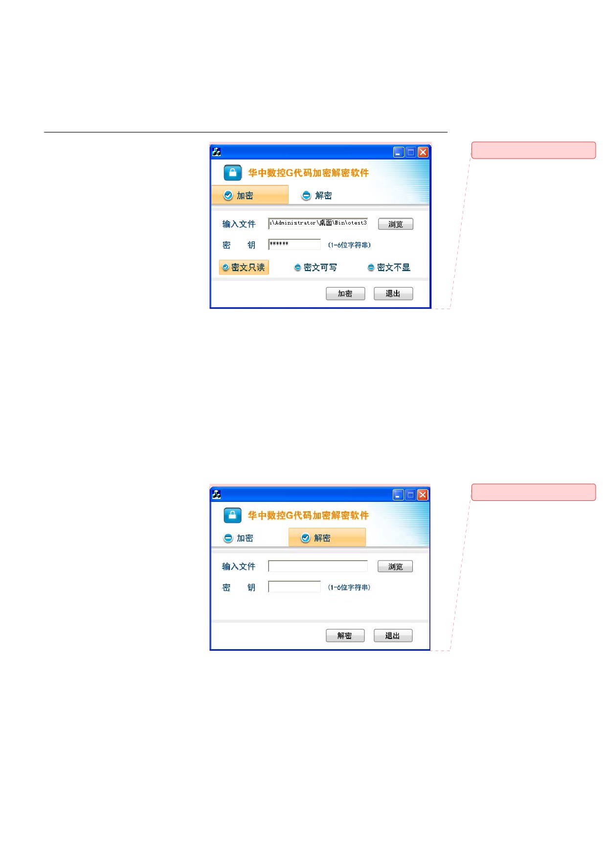
5.
Run the software of G code file
批注 [z13]: 中文图
key on the PC. See the figure
below:
6.
Encryption: Click Browse, select a G code file, enter the file key
above, and click Encrypt. The system generates an encrypted G
code file.
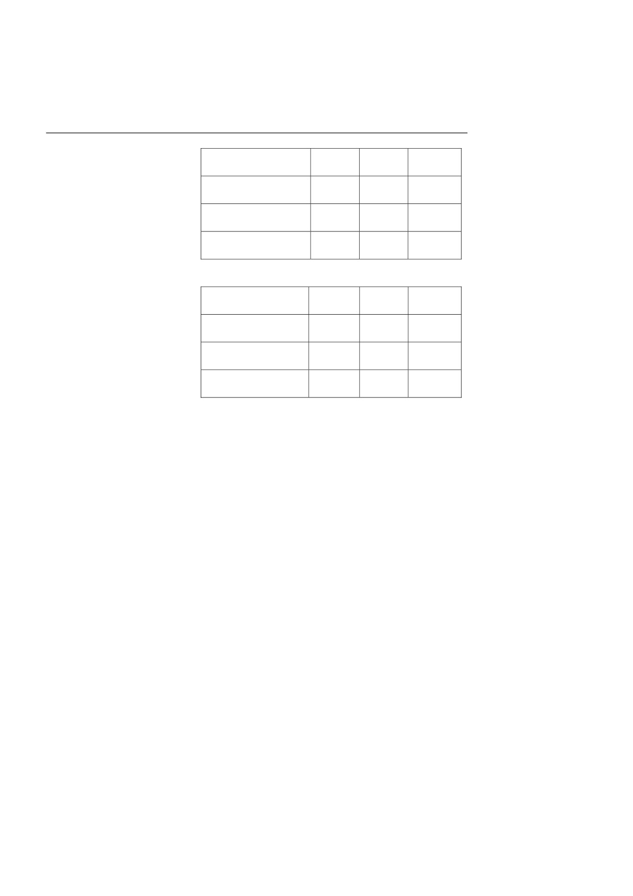
Read-only: The encrypted file cannot be modified.
Writable: The encrypted file can be edited.
Not display: The system does not display the encrypted file
content.
7.
Decryption: Click Browse, select a G code file, enter the file key
above, and click Decrypt.
批注 [z14]: 中文图
72
5. Program Editing and Management
[G Code Encrypted File
Display
Edit
Operation
Key Mapped]
Function
Function
Function
Not display
Blank
Not
Allowed
G code encryption type
support
Writable
Able to be
Editable
Allowed
Browsed
Read-only
Able to be
Not
Allowed
Browsed
support
[G Code Encrypted File
Display
Edit
Operation
Key Not Mapped]
Function
Function
Function
Not display
Blank
Not
Not
support
allowed
Writable
Unreadable
Not
Not
support
allowed
Read-only
Unreadable
Not
Not
support
allowed
73
5. Program Editing and Management
5.2 Edit Program
5.2.1 Edit Program
Programs existed in the system
Press Prog → EDIT to edit the currently loaded file.
buffer
No program existed in the system
Press Prog → EDIT. The system automatically creates a file. Press
buffer
Enter to edit the created file.
Shortcut key
-
Del: Delete the character right to the cursor and maintain the cursor
position. The remaining characters right to the cursor will shift
leftwards accordingly with one-character space.
-
PgUp: Move the program to be edited one screen up to the program
header and maintain the cursor position. If it has reached the
program header, the cursor will move to the first character in the
first row of the program.
-
PgDn: Move the program to be edited one screen down to the
program end and remain the cursor position. If it has reached the
program end, the cursor will move to the first character in the last
row of the program.
-
BS: Delete the character left to the cursor and the cursor will shift
leftwards with one-character space. The remaining characters right
to the cursor will shift leftwards accordingly with one-character
space.
-
◄: The cursor shifts leftwards with one-character space.
-
►: The cursor shifts rightwards with one-character space.
-
▲: The cursor shifts one row upwards.
-
▼: The cursor shifts one row downwards.
-
ALT+B: Define block header.
74
5. Program Editing and Management
- ALT+E: Define block end.
- ALT+D: Delete a block.
- ALT+X: Cut
- ALT+C: Copy
- ALT+V: Paste
- ALT+F: Find
- ALT+N: Find next
- ALT+R: Replace
- ALT+L: Delete a line.
- ALT+H: Move to file header
- ALT+T: Move to file end
Attention
You must execute the file again after editing.
5.2.2 Create Program
Operation procedure
1.
Press Prog → EDIT → NEW.
2.
Enter a file name, and press Enter to create a file.
Attention
1.
The default directory for created files is the prog directory in the
system disk.
2.
The created file name cannot conflict with an existing one.
5.2.3 Save Program
Operation procedure
Press Prog → EDIT → SAVE to save a specific file.
Attention
When the program is a read-only file, the system will prompt you that
the file saving is failed when pressing the SAVE key. In this case, yous
may only use the SAVE AS function.
75
5. Program Editing and Management
5.2.4 Save as
Operation procedure
1.
Press Prog → EDIT → SAVE AS.
2.
Use the cursor keys to select the target folder.
3.
Press ► to move to the input box, and enter a file name.
4.
Press Enter to save the file as another file.
5.2.5 Block Operation
Operation procedure
1.
Press Prog → EDIT → BLOCK EDIT.
2.
The block operation function is the same as the shortcut function
described in section 5.2.1.
5.2.6 Search a String of Characters
Operation procedure
Search files based on the entered keywords.
1.
Press Prog → EDIT → FIND.
2.
Enter the keywords, and press Enter. The system highlights the
searched characters.
3.
Press CONT. They system highlights the next searched characters.
5.2.7 Replace a String of Characters
Operation procedure
1.
Press Prog → EDIT → REPLACE, enter the characters to be
replaced.
2.
Press Enter.
3.
Enter the characters used to replace the previous ones.
4.
Press Enter. The system will ask whether to replace all.
76
5. Program Editing and Management
-
Press Y to replace all
thecurrently searched characters.
searched characters.
a.
Press Y to replace the currently searched characters.
-
Press N. The system will
b.
Press N to cancel the current replacement.
ask whether to replace
5.2.8 Change File Properties
Attention
The function is available only for the machine manufacturer, CNC
manufacturer and administrator.
Operation procedure
1.
Load the file to the machining buffer (see section 5.1.1).
2.
Press Prg → EDIT → ALLOW/NOT ALLOW.
-
Not allow editing: Allow to view the program code, but not
allow to modify it.
-
Allow editing: Allow to edit the program.
77
5. Program Editing and Management
5.3 Program Management
5.3.1 Delete Program File or File Folder
Operation procedure
1.
Press Prog → P.MGT, and select a drive where the program file is.
2.
Use the direction keys to move the cursor to the program file or file
folder to be deleted.
3.
Press Del, the system displays the message to prompt you whether
to delete the current file or file folder. Press Y to delete it from the
current storage, or press N to cancel the deletion.
Attention
The current running program cannot be directly deleted.
You may use the FLAG function to select multiple programs to delete.
The deleted file cannot be restored.
5.3.2 Copy and Paste Programs
Operation procedure
You may use this function to copy and paste a file to a defined folder.
1.
Press Prog → P.MGT, and select a file to be copied.
2.
Press COPY.
3.
You may press FLAG to select multiple files.
4.
Select the target folder (The folder cannot be the same as the current
one).
5.
Press PASTE to paste the file to the defined folder.
78
5. Program Editing and Management
5.3.3 Search Programs
Operation procedure
You may search files based on entered file name.
1.
Press Prog → P.MGT → FIND
2.
Enter the file name to be searched, and press Enter. The system
highlights the searched results.
5.3.4 Change Program Name
Operation procedure
1.
Press Prog → P.MGT → RENAME.
2.
Enter the new file name in the editing box.
3.
Press Enter.
Attention
The name of the program which is under machining cannot be modified.
5.3.5 Sort Programs
Operation procedure
Programs can be sorted by time/name.
1.
Press Prog → OPEN → NAME to sort files by file name.
2.
Press Prog → OPEN → TIME to sort files by file time.
5.3.6 Create a Program File or File Folder
Operation procedure
different disks.
1.
Press Prog → P.MGT. The system displays the program file list.
2.
Use the cursor keys to select a disk:"System Disk", "USB", or "CF
Card".
3.
Press Enter to create a folder in the selected directory.
4.
Press New Folder, and enter a folder name.
5.
Press Enter again.
You may create sub directories in
79
5. Program Editing and Management
80

5. Program Editing and Management
5.4 Random Line
Scanning mode
Before running program, the system scans all modal information above a
random line. The specified line inherits the coordinates, tool
compensation and other information of the previous lines. There are two
scanning modes: scanning without Z axis return, scanning with Z axis
return. If the program is large, it may take a long time for scanning the
modal information. Sub program scanning is supported.
Non-scanning mode
The system does not compute the previous modal information of a
random line. The mode is the default system status.
Parameter settings
Parameter settings related to random line operations:
040113: The order of axis motion for random line.
Parameter No.
Description
Value
Effective Mode
040113
Random
line
1
Save
scanning
Parameter value:
0: Non-scanning mode (default);
1: Scanning
without Z axis return; 2: Scanning with Z axis return
Example:
G54
….
Z10
N1X10y10
….
M30
When 040113=1, and the random line is specified as N1; only X/Y
axes are moved.
When 040113=2, and the random line is specified as N1; X/Y/Z
axes are moved.
040114: The order of axis motion for random line.
81
5. Program Editing and Management
The relationship between the parameter value and axis is as below:
1
2
3
4
5
6
7
8
9
X
Y
Z
A
B
C
U
V
W
The value from 1 to 9 corresponds the axis X/Y/Z/A/B/C/U/V/W
respectively. The 0 indicates that the axis is not configured.
For milling machines, when 040114=211, firstly the X/Y axes move
in place, and then the Z axis moves.
For lathe machines, when 040114=101, the X/Z axes move in place
simultaneously.
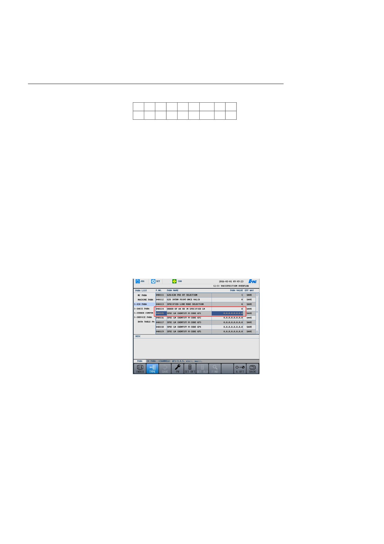
For channel parameters 040115-040124, M code group can be
identified by random line.
The type is BYTE[8], supporting up to eight numbers, which must
be separate by the "," or "." symbol.
Only the M command in parameters can be restored. Therefore, a
maximum of 10 M command groups is supported, and each group
has eight M codes.
For example: Set M command group 1 to 3, 4, 5, which indicates
that M3/M4/M5 are in the same group.
Attention
1.
For the M commands of the same group obtained in the scanning
mode, only the last M command is valid.
2.
For the T commands obtained in the scanning mode, only the last T
command is valid for lathe machines.
82
5. Program Editing and Management
3.
For the armless type ATC of
milling machines, M6 should be
same line with T codes.
in the
4.
For the S commands of the same group obtained in the scanning
mode, only the last S command is valid. A maximum of four S
commands is supported for the channel.
83
5. Program Editing and Management
5.4.1 Scanning Mode
Operation procedure
1.
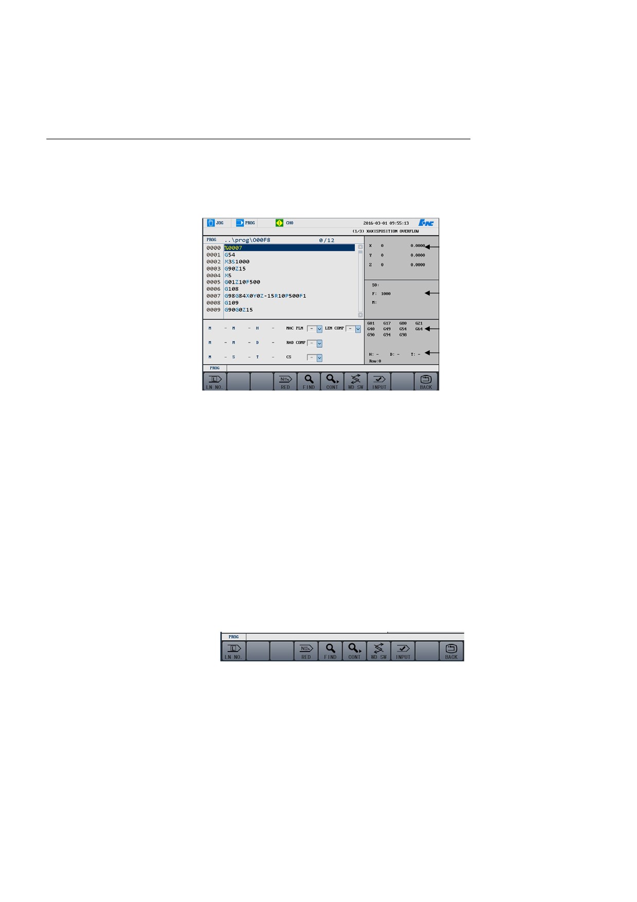
Press Prog → BLOCK → SCAN to enter the scanning mode.
①
②
③
④
The system displays the scanned M/S/T value and its line number on the
interface for users to view.
1.
Scanned axis position
2.
Scanned spindle speed, feed rate, and M command
3.
Current G modal commands
4.
Scanned tool compensation number, T command, and line number
5.4.1.1 Specify Line Number
Operation procedure
1.
Press the Feed Hold key on the control panel (the indicator is on) to
enter the feed hold mode.
2.
Press Prog→ BLOCK → LN NO., and enter the number of the
line from which the execution starts. See the figure below:
3.
Press Enter.
4.
Press the Start button on the control panel to start the operation
from the specified line.
5.4.1.2 Specify N Number
84
5. Program Editing and Management
Operation procedure
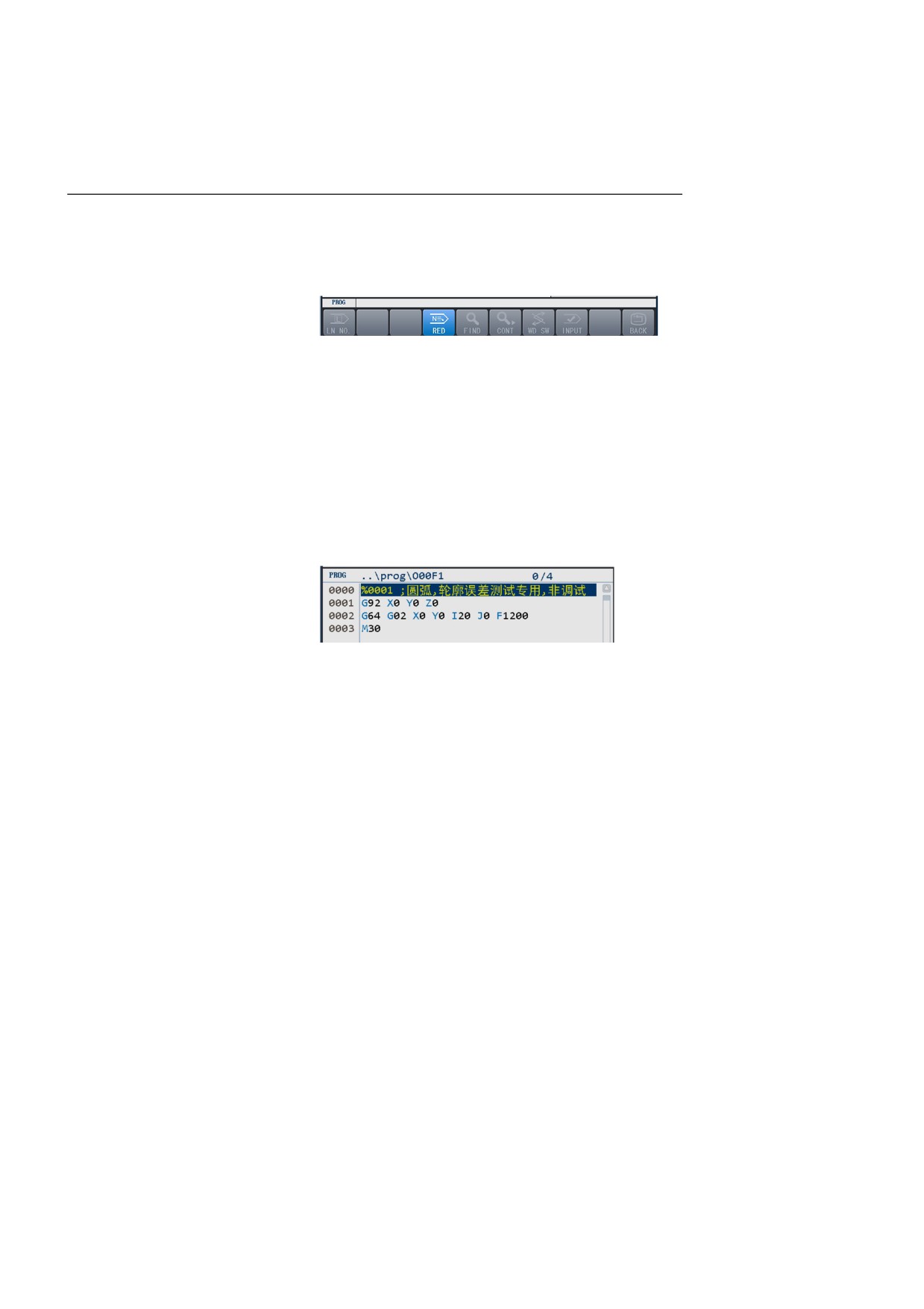
control panel (the indicator is on) to enter the feed hold mode.
2.
Press Prg → BLOCK → RED, and enter the N number from
which the execution starts. See the figure below:
3.
Press Enter.
4.
Press the Start button on the control panel to start the execution
from the specified line.
1.
Press the Feed Hold key on the
Attention
when the following conditions are met:
1.
N number exists in the G code file.
2.
The total G code lines can be displayed.
3.
The program is less than 22M.
This function is available only
5.4.1.3 Find
Operation procedure
Search keywords, and start execution from the line where the keyword
is.
1.
Press Prog → BLOCK → FIND.
2.
Enter the keyword, and press Enter. The searched keyword is
highlighted.
3.
Press CONT to find the next keyword.
4.
Press Enter again. The cursor points to the line where the keyword
is.
5.
Press the Start button on the control panel to start the execution
from the specified line.
85
5. Program Editing and Management
5.4.2
5.4.3 Non-scanning Mode
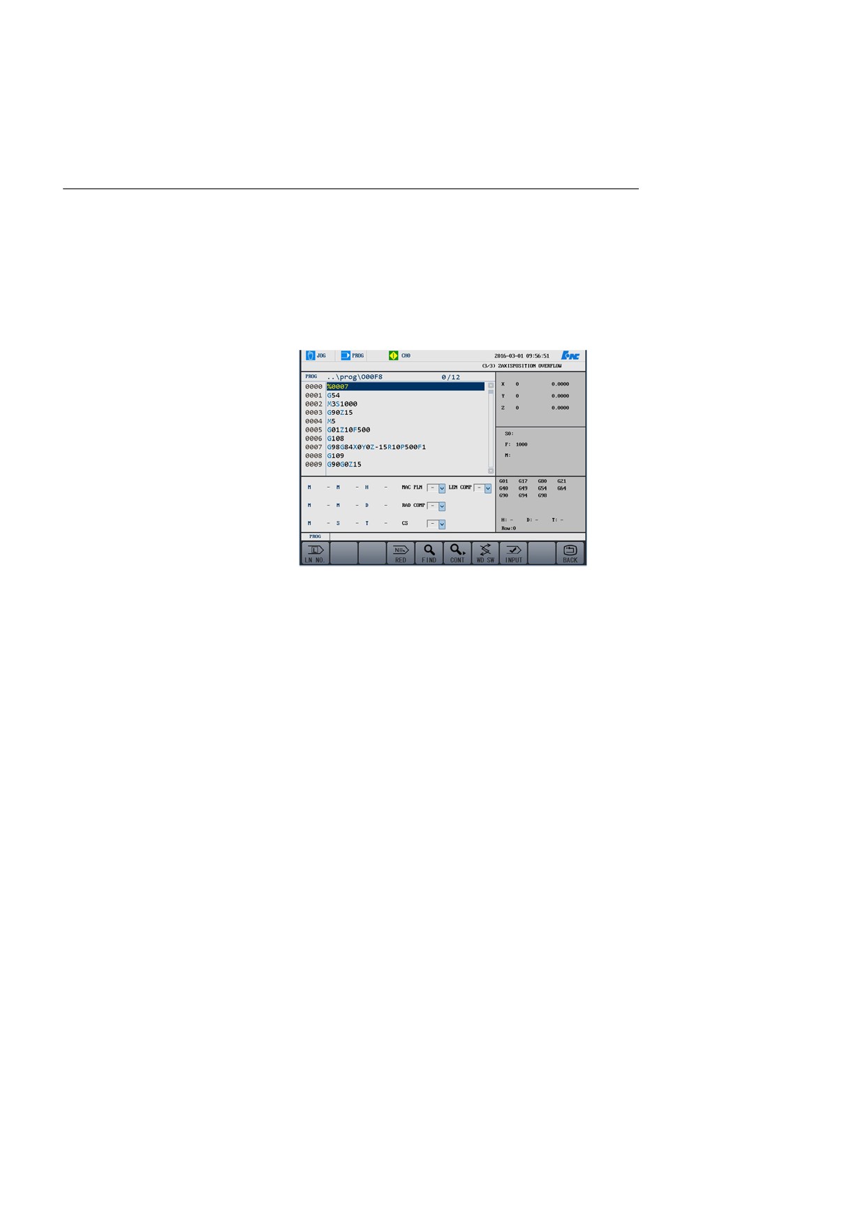
Operation procedure
SCAN to enter the non-scanning mode.
2.
If you press the "WD SW" button, you can switch to the lower part
of the window to enter the M/S/T code. You can enter five M
commands and other commands. Press the Enter key to confirm the
input, then press the Start button. The system will execute the
M/S/T command first, and then execute the specified line.
1.
Press Prog → BLOCK →Non
5.4.3.1 Specify Line Number
Operation procedure
See section 5.4.1.1.
5.4.3.2 Specify N Number
Operation procedure
See section 5.4.1.2.
5.4.3.3 Find
Operation procedure
See section 5.4.1.3.
Attention
86
5. Program Editing and Management
Don’t move the cursor over the
subprogram during the random
line operation.
87
5. Program Editing and Management
5.5 Verify Program
This function is used to verify the programs in the machining buffer and
report errors if there is any.
New programs that have never been run on the machine should be
verified before auto running.
Operation procedure
1.
Call the program that need to be verified (Prog → OPEN).
2.
Press the Auto or Single Block key on the control panel to enter the
program operation mode.
3.
Under the Prog menu, press Verify. The work mode displayed on
the system interface changes to Auto Verification.
4.
Press the Start button on the control panel to start the program
verification.
5.
If a program error occurs, the system displays the message where
the error is.
Attention
1.
The machine doesn’t run during program verification.
2.
It is recommended to select difference graphs for verification to
ensure correct program. For detailed information, see section 7
(Graph Display).
3.
The verification speed depends on the feed adjustment override. It
may help you to view the tool path.
88
5. Program Editing and Management
5.6 Stop Program
Operation procedure
This function is used to pause the running during program working.
1.
Press Prog → Stop. The system prompts you that the operation is
paused and whether to cancel the current program (Y/N).
2.
Press N to pause the current operation, but save the current program
modal information (In this case, you may press the Start button to
proceed the program from the pause point).
3.
Press Y to stop the program and unload the current program modal
information (In this case, users must select the program and restart
it from the beginning).
89
5. Program Editing and Management
5.7 Restart Program
Operation procedure
This function is used to restart a program from the beginning after the
program is stopped.
1.
Press Prog → REWIND. The system prompts you whether to
restart the current program (Y/N).
2.
Press N to cancel the restart.
3.
Press Y. The cursor moves to the beginning of the program. Press
the Start button to restart the program from the beginning.
90
5. Program Editing and Management
5.8 Craft File
Craft file is used to provide the operator with auxiliary information about
Craft file display and management
processing. Craft file and G-code files are matched and bound via
filename. After loading G code, you may browse the craft file which
matches the G code to know the craft flow.
Design craft file
1.
You should finish the craft file when creating G codes.
2.
The craft file uses
24-bit bmp pictures with color
790*440
resolution.
3.
The craft file is associated with the program, so the craft file is
named as the main program name (removing 'O' or 'o' from the
name) plus the craft file number (0 to 9).
Example 1: If the main program name is "OA347F.nc", then the
craft file name should be "A347F_0.bmp" to "A347F_9.bmp".
Example 2: If the main program name is "oWErt6", then the craft
file name should be "WErt6_0.bmp" to "WErt6_9.bmp".
Note: The suffix of the .bmp file is lowercase of "bmp".
4.
A program can have up to 10 craft files.
Transmit craft files to the CNC
After the G code file of the main program is transmitted from the host
system
computer to the CNC device, the craft file is also transmitted from the
host computer to the CNC device.
Attention: The craft file and main program file are in the same directory.
Example: The main program is transmitted to the prog directory, and the
craft file is also transmitted to the prog directory.
The main program is transmitted to the 123 folder under the prog
directory, and the craft file is also transmitted to the 123 folder under the
prog directory.
91
5. Program Editing and Management
View craft file
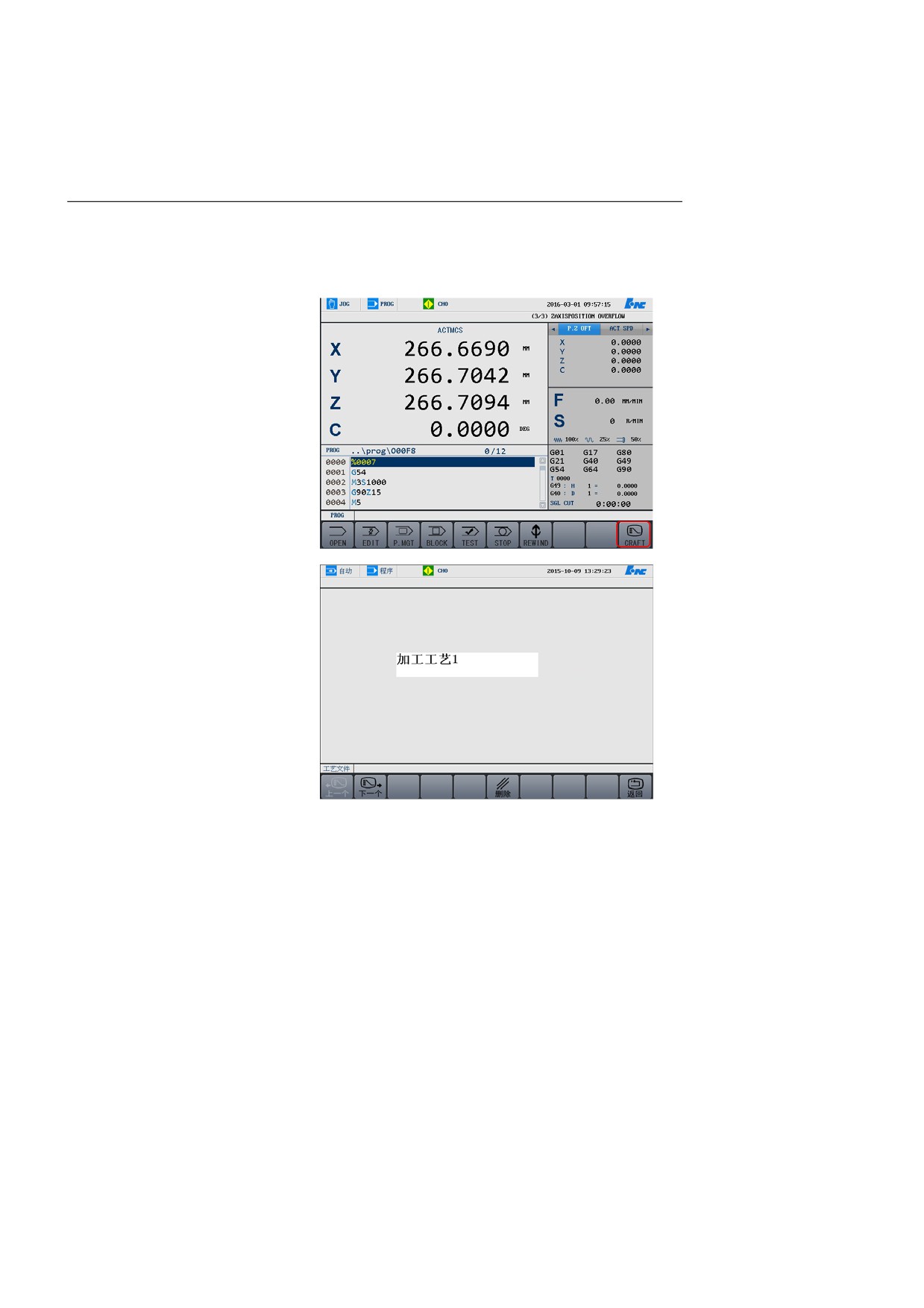
1.
After automatically or manually loading programs, you may press
CRAFT to view the craft file corresponding to the loaded main
program. See the figure below:
2.
If there are multiple craft files, press the PREVIOUS or NEXT
menu to switch files.
3.
During program execution, you may view craft files.
1.
The associated craft files will be deleted when the main program is
deleted.
Delete craft files
2.
Workshop manager or higher permission may delete the craft files
displayed under CRAFT.
3.
You may view or manage craft files corresponding to multi-channel
programs.
92
5. Program Editing and Management
5.9 Workpiece Measurement
Move the tool on the spindle via manual or hand-wheel feel, to make it
contact with the workpiece, so that the coordinate position can be
measured. Specify the measured value to the defined workpiece
coordinate system (G54 - 59 or G54.XX).
Operation procedure
1.
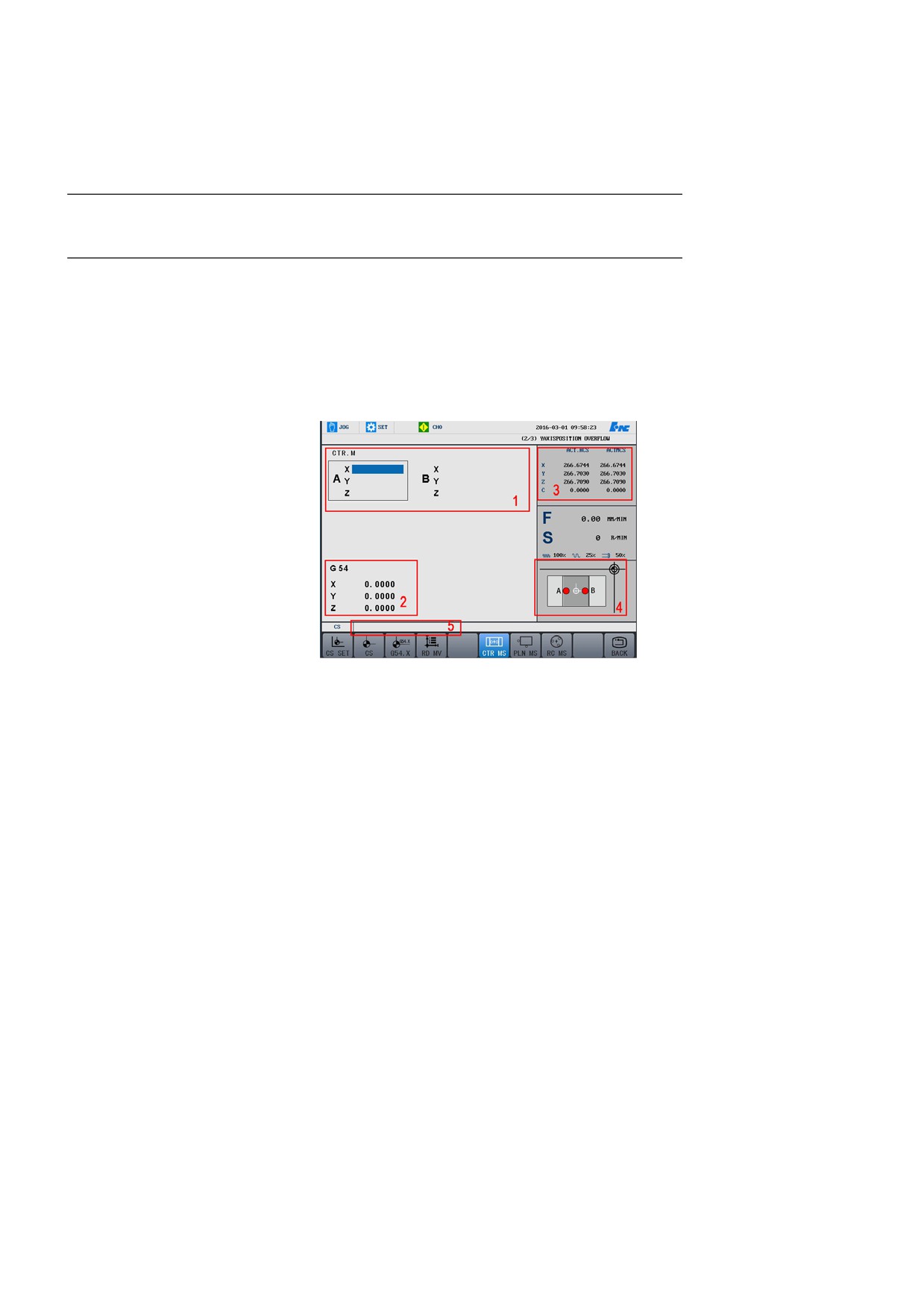
Select Set on the control panel to enter the Set menu, press WC MS
to enter the interface shown as the figure below:
Options on the interface:
Display area
1—Measure value display area: displays the
current measurement position and measurement mode. Select
BACK to clear the recorded coordinate values.
Display area 2—Coordinate system setting area: displays the
coordinate system and value to be set.
Display area 3—Position recording area: display the current
relative actual coordinate system and machine actual
coordinate.
Display area
4—Guide diagram: display the schematic
diagram of the current measurement mode.
Display area
5—Value input box: When selecting G54.X,
“Enter the coordinate system number : P”will be displayed in
the input box, then nter one value of 0~60.
93