HNC-818. User Manual - page 1
Contents
Contents
Preface
i
Contents
ii
I overview
4
II Operation
6
1 Operation Device
7
1.1 Display Screen
8
1.2 NC Keyboard
9
1.3 Machine Control Panel
10
1.4 Hand-Held Unit
11
1.5 Operation Panels
12
2 Power On, Power Off and Emergency Stop
14
2.1 Power On
15
2.2 Reset
16
2.3 Reference Returning
17
2.4 Emergency Stop
19
2.5 Over-Travel Release
20
2.6 Power Off
21
3 Manual Operation
22
3.1 Manually Move the Coordinate Axis
23
3.2 Spindle Control
27
3.3 Machine Lock and Axis Z Lock
29
3.4 Manual Data Input (MDI)
30
4 Settings
33
4.1 Tool Management
34
4.2 Coordinate System Settings
39
4.3 Clear RCS
41
4.4 Parameter Settings
42
5 Program Editing and Management
68
5.1 Select Programs
69
5.2 Edit Program
74
5.3 Program Management
78
5.4 Random Line
81
5.5 Verify Program
88
5.6 Stop Program
89
5.7 Restart Program
90
5.8 Craft File
91
5.9 Workpiece Measurement
93
ii
Contents
6 Operation Control
97
6.1 Start, Pause and Stop
98
6.2 Dry Running
100
6.3 Over-Block Operation
101
6.4 Optional Stop
102
6.5 Single Block Operation
103
6.6 Breakpoint Related Operation
104
6.7 Intervention at runtime
107
7 Position Information
109
7.1 Coordinate Display
110
7.2 Text Display
111
7.3 Graph Display
112
7.4 Joint Display
114
8 Diagnosis
115
8.1 Import System Logo Interface
116
8.2 Alarm Display
118
8.3 Alarm History
119
8.4 Ladder Monitoring
122
8.5 Input and Output
128
8.6 Status Display
129
8.7 Macro Variables
130
8.8 Servo Adjustment
132
8.9 Machining Information
146
8.10 Version
148
9 User Operation and Maintenance Information
150
9.1 Environmental Requirements
151
9.2 Grounding
152
9.3 Power Conditions
153
9.4 Clean Fan Filter
154
9.5 Operations After Being Left Unused
155
I overview
4
The following models are described in the manual:
Name
Model
HNC-818A Milling NC Unit
HNC-818A-MU
HNC-818B Milling NC Unit
HNC-818B-MU
II Operation
6
1. Operation Device
1 Operation Device
This chapter describes the operator area and system operation interface
of HNC-818.
Display and Operation Panel
NC Keyboard
Machine Control Panel
Hand-Held Unit
System Operation Interface
7
1. Operation Device
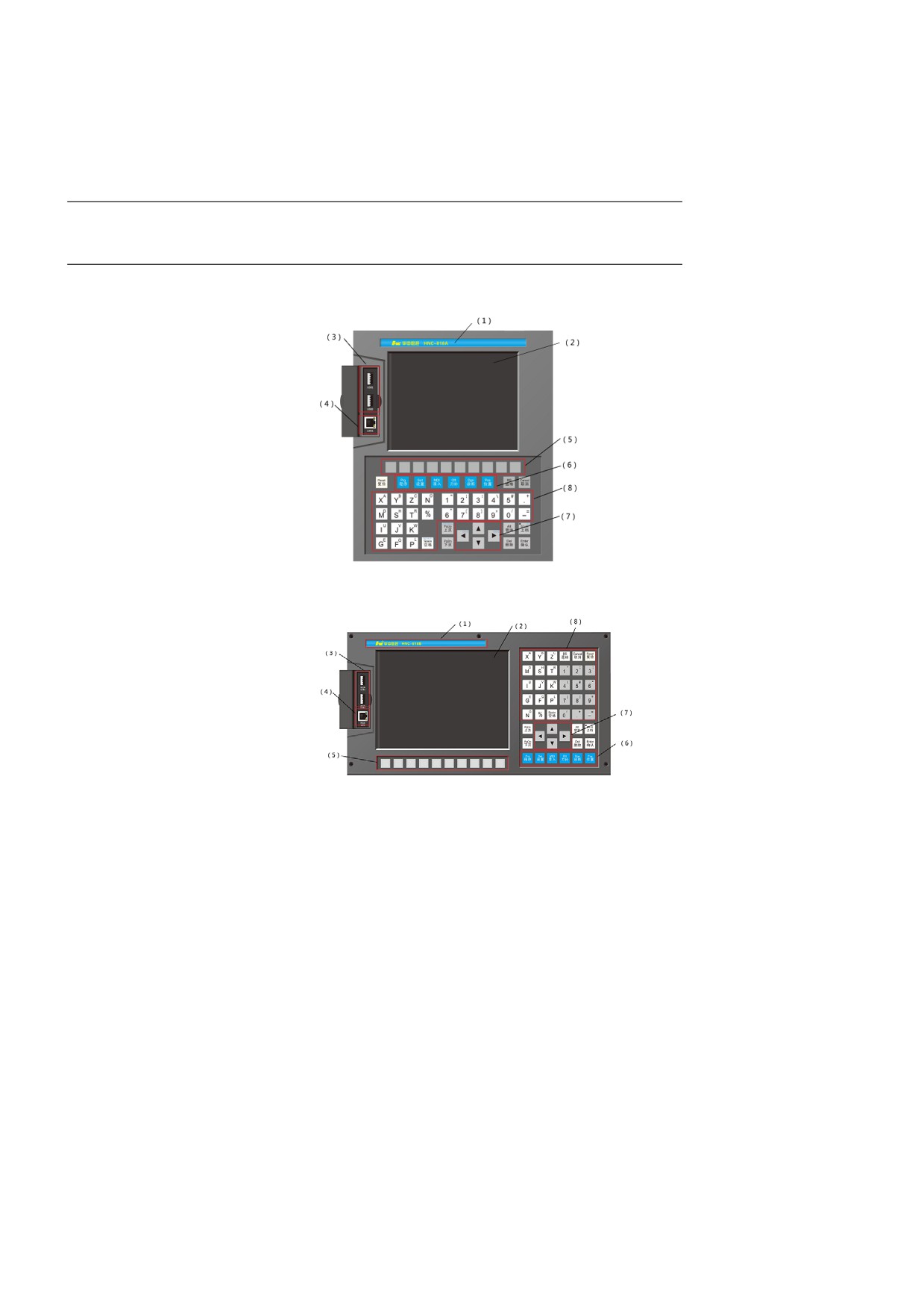
1.1 Display Screen
HNC-818A-MU
y
8.4-inch color liquid crystal display (resolution: 800×600)
HNC-818B-MU
y
10.4-inch color liquid crystal display (resolution: 800×600)
1. Company Logo
2. Display screen
3. USB interface
4. Ethernet interface
5. Soft keys
6. Functional keys
7. Cursor control
8. Characters and numbers
8
1. Operation Device
1.2 NC Keyboard
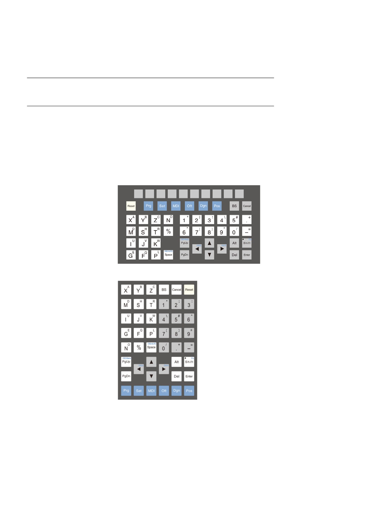
The NC keyboard includes a compact MDI keys, main menu keys and
functional keys, which are mainly used for the programming, parameter
input, MDI and system management and other operations
-
MDI keys: Most of them have the function of the Shift key. For
example, you may press the Shift key and a letter/number key
simultaneously to input the characters in the upper corner.
HNC-818A
HNC-818B
9
1. Operation Device
1.3 Machine Control Panel
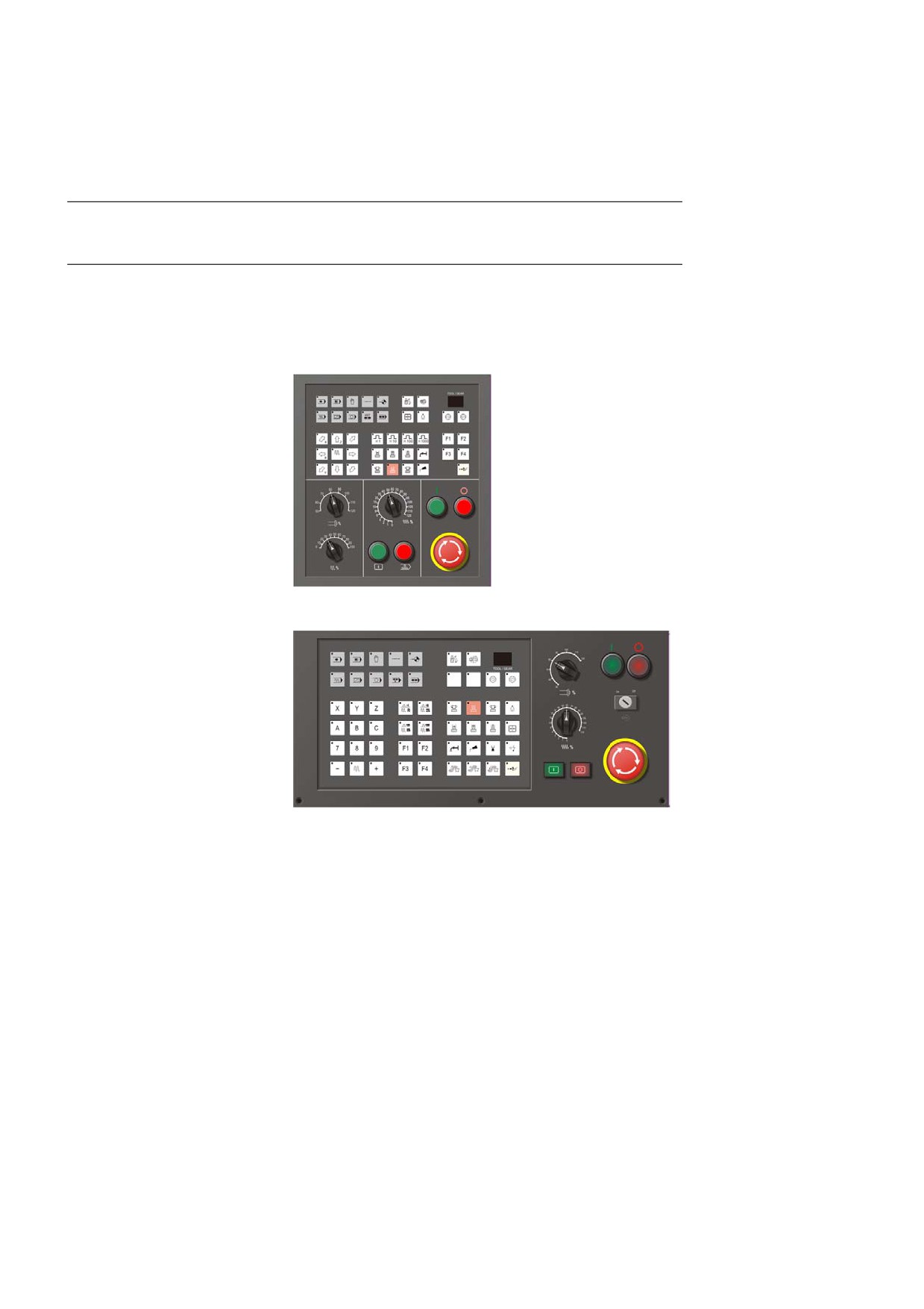
The machine control panel is used to control the motion and machining
process.
HNC-818A-MU
HNC-818B-MU
10
1. Operation Device
1.4 Hand-Held Unit
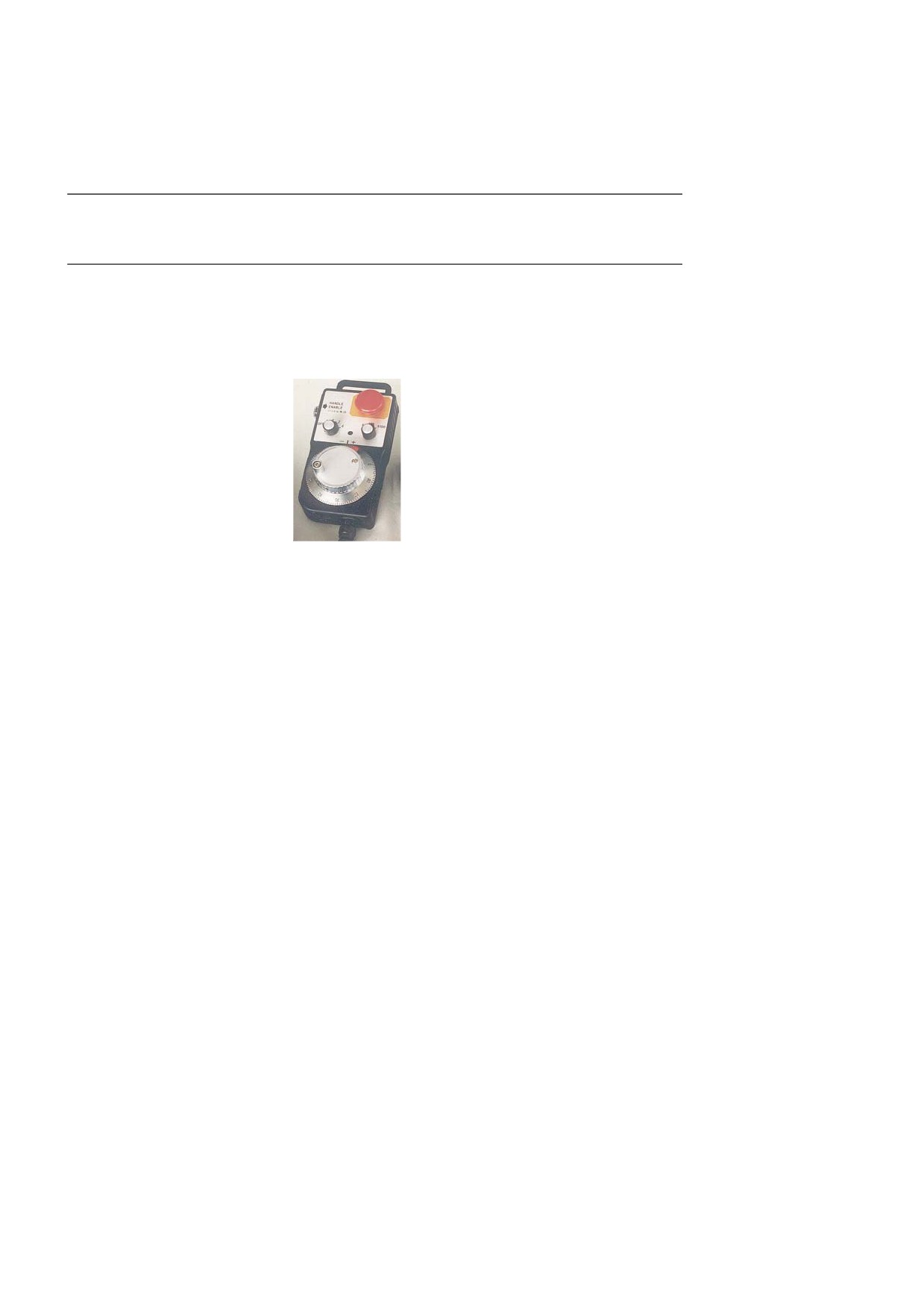
The hand-held unit, which is used to feed coordinate axis by hand,
consists of a manual pulse generator (MPG) and coordinate axis
selection switch. The structure of the handheld unit is shown belo-
w (the appearance as per the actual products):
11
1. Operation Device
1.5 Operation Panels
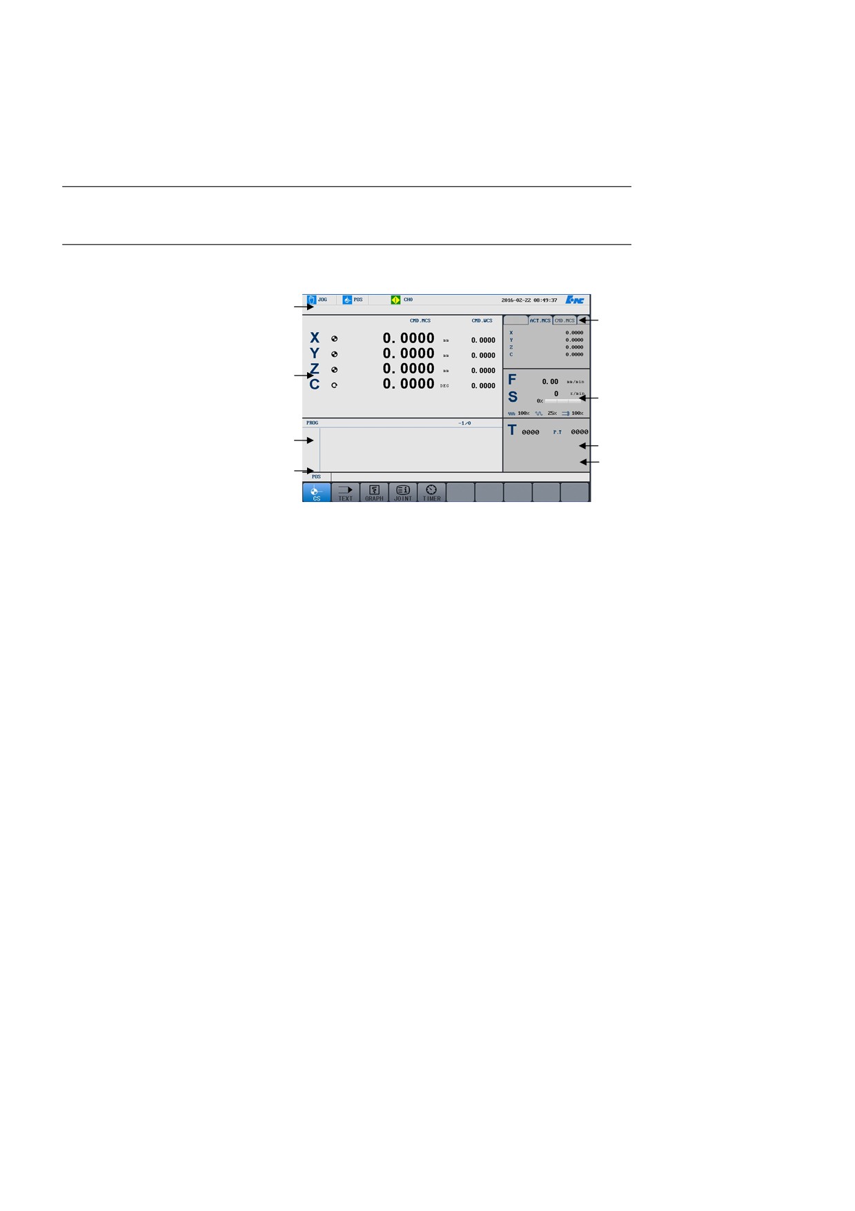
The operation interface of HNC-818 is the following:
1
5
2
6
3
7
8
4
1.
Title bar
• Machining mode: Switch the machining mode among Auto,
Single Block, Manual, Incremental, Reference, and Emergency
Stop.
• Main menu: Display the currently activated main menu.
• Workstation: Display the current workstation.
• Channel information: Display the work status of each channel,
such as "Normal", "Feed Hold", or "Error".
• System time: Display the current system time
(it can be
selected in the machine parameter).
• System alarm information.
2.
Graphical display: The information displayed is based on the
selected menus.
3.
Code G display: Preview or display the G code of the machining
program.
4.
Menu command bar:run functional operation through corresponding
functional key in the menu command bar.
5.
Tabs: View different coordinate systems by switching the tabs.
6.
Supplementary functions: Display the F/S information in automatic
machining and adjustment information.
12
1. Operation Device
7.
Tool information: Display the current tool.
8.
Modal G and Machining time(in the main menu “Program":Display
the G modal during machining and the machining time.
13
2. Power On/Off and Emergency Stop
2 Power On, Power Off and Emergency Stop
The chapter describes the operations on power on/off, emergency stop,
reset, reference returning and over-travel release.
14
2. Power On/Off and Emergency Stop
2.1 Power On
Operation procedure
1.
Check and make sure the machine is normal to run.
2.
Make sure the power supply and voltage to meet requirements and
the wiring is correct.
3.
Press the Emergency Stop button.
4.
Electrify the machine.
5.
Electrify the CNC system.
6.
Make sure the indicators on the machine control panel are working.
7.
After electrifying the CNC system, the system automatically runs
with the machining mode being Emergency Stop.
15
2. Power On/Off and Emergency Stop
2.2 Reset
Operation procedure
When the system enters the operation interface in a power-on state, the
initial operation mode is displayed as Emergency Stop. The Emergency
Stop button should be pulled up in the clockwise direction to reset the
system and enable the servo. Then the system could control the
machining.
16

2. Power On/Off and Emergency Stop
2.3 Reference Returning
The control of the Machine motion is based on the establishment of
coordinate system . Therefore, after the system is reset, each machine
axis must return to the reference point. Follow the instructions below:
1.
If the currently operation mode is not Home Return, press the
Reference Return button on the control panel to make sure that the
system is in the Home Return mode.
2.
Based on the X-axis machine parameter of REF Direction, press X
and the direction key (the value of REF Direction is "+"). After the
X- axis returns to the reference point, the indicator of the X key is
on.
3.
Return the Z axis to the reference point with the same method.
4.
After return every axes to the reference point, the machine
coordinate system is established.
Attention
1.
Return all axes to the reference point as soon as the power is on in
order to ensure the axis coordinate is correct. After that, other
operations can be performed.
2.
Press the direction keys of X, Y, and Z simultaneously to return the
three axes to the reference point at the same time.
3.
Before returning the axis to the reference point, make sure that the
axis is in the opposite direction of REF Direction (e.g. if the REF
Direction of the X axis is "-", then make sure the X axis direction is
"+" before returning it to the reference point); otherwise, manually
move the axis until it meets the requirement.
4.
When returning axis to the reference point, if over-travel occurs,
press the over-travel release key on the control panel and manually
move the axis in the opposite direction to exit the over-travel status.
5.
After return each axis to the reference point, the reference return
doesn’t need to be performed again (including alarms and pressing
the Emergency Stop button ) unless a servo drive device alarm is
reported.
6.
When returning axis to the reference point, if the Reset key is
pressed before the Reference Returning key is pressed, the home
returning will be canceled.
17
2. Power On/Off and Emergency Stop
7.
When returning axis to the reference point, if the Reset key is
pressed after the Reference Returning key is pressed, the home
returning will not be canceled.
18

2. Power On/Off and Emergency Stop
2.4 Emergency Stop
During machining, press the Emergency Stop (ES) button to enter into
the "Emergency Stop" mode in case of emergency. Once the ES button is
pressed, the servo feed and the spindle rotating are disabled (the feed
driver power supply is cut off in the control cabinet). Release the ES
button ( turn the ES button clockwise ), then the system enters the reset
status.
Make sure that the trouble has been solved before releasing the ES status.
Return the axis to the reference point again after releasing the ES button
to ensure correct coordinate position.
Attention
Press the ES button before turning the power on or off to avoid
electric shock.
19
2. Power On/Off and Emergency Stop
2.5 Over-Travel Release
There is a limit switch at each end of the axis stroke to avoid servo
collision. If the servo meets the limit switch, the over travel occurs. The
situation that the axis travels over (the relevant indicators is on) is treated
as an emergency stop by the system. Follow the instructions below to
exit over travel:
1.
Set the operation mode to JOG or HANDLE.
2.
Press down and hold the over travel release key (the controller will
temporarily ignore the emergency).
3.
In the manual (hand-held) mode, move the axis to the opposite
direction.
4.
Release the over travel release key.
5.
Then the status bar of the screen shows "Normal" instead of
"Error" , which means the system is back to normal and the
operation can be allowed.
Attention
Please pay attention to the motion direction and speed when moving the
tool out of over-travel to avoid tool collision with the machine.
20

2. Power On/Off and Emergency Stop
2.6 Power Off
Operation Procedure
1.
Press the Emergency Stop button to cut off the servo power.
2.
Cut off the CNC power.
3.
Cut off the machine power.
21
3. Manual Operation
3 Manual Operation
The section of manual operation includes the hand-held units and
machine control panel. This chapter describes the following content:
Manually Move the Coordinate Axis
Manually Control Spindle
Lock Machine
Manual Data Input (MDI)
Other manual operations
22

3. Manual Operation
3.1
Manually Move the Coordinate Axis
The manual operation related to machine axis movement is conducted on
the hand-held units and control panel with relevant keys such as
operation mode selection, axis manual, incremental rate, feed rate
adjustment, and rapid adjustment , etc.
3.1.1
Manual Feed
Press this key (the indicator is on) to enter the Manual mode. In this
mode, the cutting tool can be jogged along the motion axis. The
following describes the motion along the X axis:
1.
Press the key X and the direction key (the corresponding indicator
is on) to move along axis X continuously in the positive or negative
direction.
2.
Release the key X and the direction key
(the corresponding
indicator is off) to decrease and stop the motion along the axis X.
Move along axis Z continuously in the positive or negative direction
with the same method.
In the Manual mode, press the axis X and Z keys simultaneously to
manually control both axes motion at the same time.
3.1.2
Rapid Traverse
key and one of the three axis keys simultaneously to rapidly move the
tool in the positive or negative direction of relevant axis.
In the manual feed mode, press this
3.1.3 Manual Feed Rate Adjustment
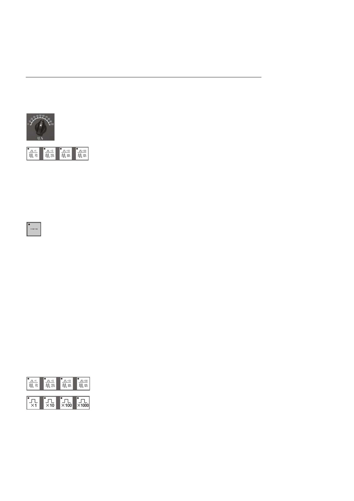
In the Auto or MDI mode, adjust the feed rate by rotating this button if
the feed rate of the F-code programming is too high or too low. The
adjustment range is 0% to 120%.
In the manual mode, this button can be used to adjust the manual feed
rate.
23
3. Manual Operation
3.1.4 Rapid Traverse Speed Adjustment
The operations on rapid traverse speed adjustment are different based on
different control panels.
1.
Rapid traverse speed adjustment button: In the Auto or MDI mode,
rotate this button to adjust the speed which is specified in the
program. The range of adjustment is from 0% to 100%.
2.
Override keys: In the Auto or MDI mode, press the corresponding
override keys to adjust traverse speed.
3.1.5 Incremental Feed
enter the incremental feed mode in which the tool can be moved
incrementally along any axis. Take the axis X as an example:
1.
Press the key X and the direction key (the corresponding indicator
is on) to move the axis X with an incremental value in the positive
or negative direction.
2.
Press the X key and the direction key (the corresponding indicator
is on) again to proceed the movement along the axis X with an
incremental value in the positive or negative direction.
3.
Perform similar operation to move the axis Z with an incremental
value in the positive or negative direction.
Press the keys for axis X and Z simultaneously to manually move the
axis X and Z with an incremental value at the same time.
Press this key (the indicator is on) to
3.1.6 Incremental Value Selection
There are different keys of incremental value based on different
24

3. Manual Operation
control panels
The incremental value is controlled
by the four keys on the control panel:
"×1", "×10", "×100", and "×1000".
The table below describes the
magnification:
relationship between the incremental
Override
×1
×10
×100
×1000
value and override keys:
Incremental
0.001
0.01
0.1
1
value (mm)
Note: These keys can be locked by each other. When you press one of
the keys (the corresponding indicator is on), then the other keys are
invalid (the corresponding indicator is off).
25
3. Manual Operation
3.1.7 Hand-wheel Feed
When the system is not in the emergency stop mode, press the
incremental key (the indicator is on) to enter the hand-wheel feed mode.
In this mode, the machine axis can be moved by the hand-held unit.
Rotate the axis selection button to choose one axis, and then rotate the
override button to the required override position. Through the rotation,
the machine axis will move an incremental distance accordingly. In the
hand-wheel feed mode, incremental feed for only one axis is supported
each time.
26

3. Manual Operation
3.2 Spindle Control
Manual spindle control is conducted with the spindle rotation keys on the
control panel.
3.2.1
Clockwise Rotation of Spindle
In the manual mode, press this key (the corresponding indicator is on) to
rotate the spindle in the clockwise direction at the specified speed until
the counter clockwise rotation key or spindle stop key is pressed.
3.2.2
Counter Clockwise Rotation of Spindle
In the manual mode, press this key (the corresponding indicator is on) to
rotate the spindle in the counter clockwise direction at the specified
speed until the clockwise rotation key or spindle stop key is pressed.
3.2.3
Stop Spindle
In the manual mode, press this key (the corresponding indicator is on) to
stop the spindle motor.
Note: The keys for spindle clockwise rotation, spindle counter clockwise
rotation, and spindle stop can be locked by each other. When you press
one of the keys (the corresponding indicator is on), then the other keys
are invalid (the corresponding indicator is off).
3.2.4 Spindle Jog
In the manual mode, press and hold this key (the indicator is on), then
the spindle will continuously rotate in the clockwise direction; Release
this key (the indicator turns off), the spindle will stop running.
3.2.5 Spindle Speed Adjustment
27

3. Manual Operation
The rotation speed of spindle can be adjusted by the spindle speed
adjustment button.
Rotate the button to an override as required, which ranging from 50% to
120%. Do not adjust the spindle speed during the rate switching of
mechanical gear .
3.2.6 Spindle Orientation
If the machine has a tool magazine, the spindle orientation function is
usually required, because the tool on the spindle must be orientated
during tool change; otherwise the tool or tool claw may be damaged.
In the manual mode, when the "Spindle Brake" is invalid (the indicator is
off), press this key, and the spindle orientation function is immediately
executed. After the orientation is completed, the indicator of the key is
on, and the spindle accurately stops at a fixed position.
28

3. Manual Operation
3.3 Machine Lock and Axis Z Lock
3.3.1 Machine Lock
The machine lock function is to lock all machine motion.
In the manual mode, press this key (the indicator is on) and then conduct
manual operation, the information of axis position changes which is
displayed on the screen , but the motion instructions from the servo axis
is not output. Therefore, the machine stops moving.
Note: The machine lock function is valid only in the manual mode.
3.3.2 Axis Z Lock
feed. When just verify the movement path in the XY plane, this function
is useful. In the manual mode, press this key (the indicator is on), and
switch to the auto mode to run the machining programs. Then the
information of Z-axis coordinate position is changed without actual
Z-axis movement.
Note: The Axis Z Lock function is invalid in the auto mode.
This function is used to disable tool
29
3. Manual Operation
3.4 Manual Data Input (MDI)
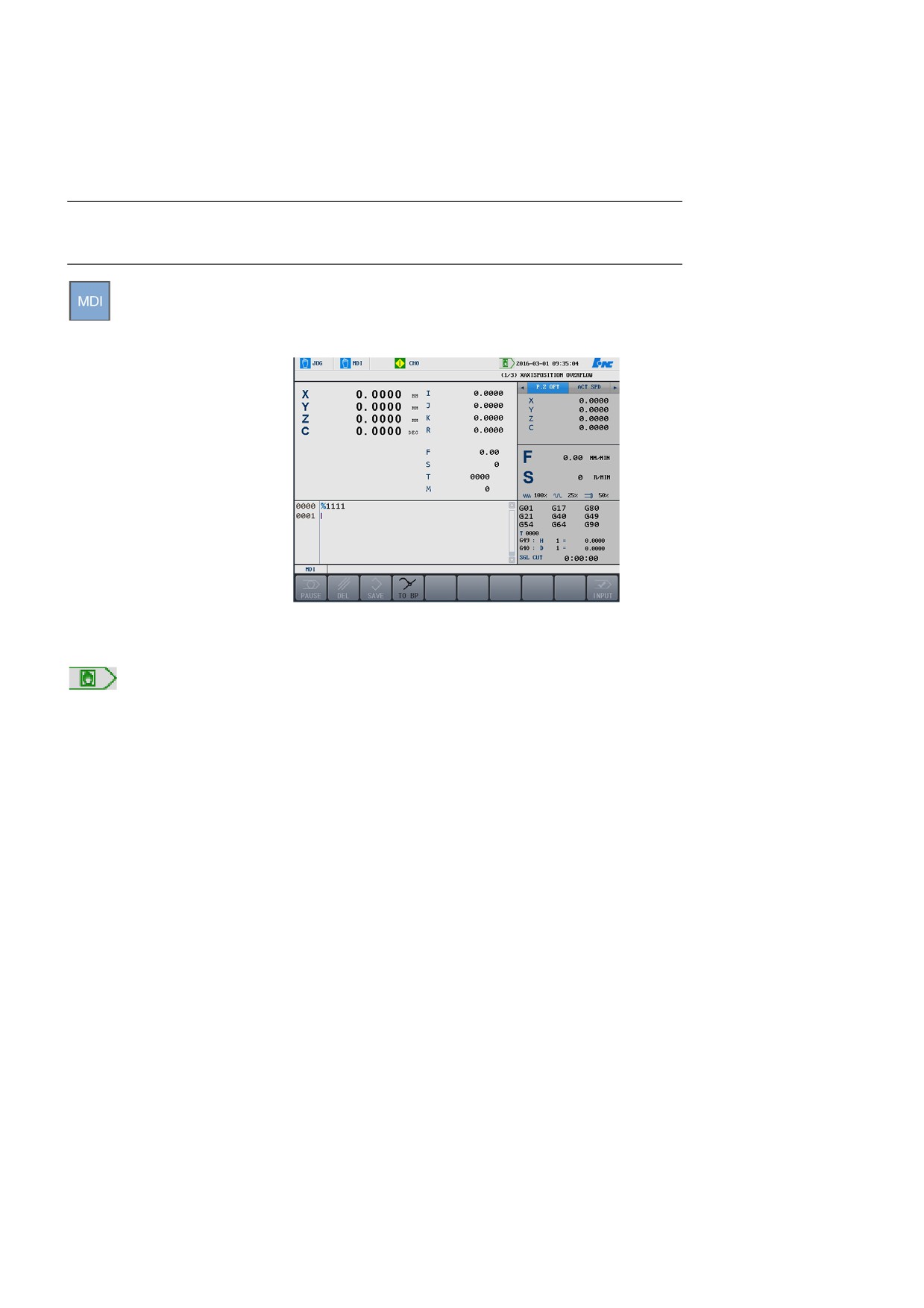
Press the MDI key to enable the corresponding function. Input and
execute one or more Code G blocks through the NC keyboard. See the
figure below:
Attention
1.
After the system enters the MDI status, the MDI icon is displayed
on the title bar.
2.
When the interface is switch to the non-program from MDI, the
system is still in the MDI status.
3.
In the auto operation mode, the system cannot enter the MDI mode,
but can do that after feed hold.
4.
In the MDI mode, press the Reset key to stop and clear the MDI
program.
3.4.1 Input MDI Command Segment
Operation procedure
The minimum unit for MDI is a valid command character. Therefore,
there are two methods to input an MDI command segment:
1.
Input once, that is, to input multiple command characters once.
2.
Input by several times, that is, to input only one character every
time.
For example, if you need to input the "G00 X100 Z1000" command
segments, you may:
1.
Directly input "G00 X100 Z1000"
30
3. Manual Operation
2.
Press Enter. Then the values after X, Z on the screen change to 100,
and 1000 respectively.
The content will be shown on the screen when a command is input. If
input wrong, press BS, ►, and ◄ keys to correct the content. If the
system detects an error after Enter, a corresponding error message will
be displayed. In this case, press Clear to clear the input information.
3.4.2 Execute MDI Commands
Operation procedure
After inputting an MDI command segment, press the Start button on the
operator panel, and then the system will run the entered MDI command.
If the MDI command is incomplete or has wrong syntax, the system will
display related error messages, and the MDI command stops.
3.4.3 Modify Commands
Operation procedure
Before running MDI command, directly input corresponding command
characters and values in a command line if needed. For example, after
entering "X100", you may input "X109" in the command line if you need
to change the X-axis value to 109.
3.4.4 Clear Current Commands
Operation procedure
After inputting MDI data, press the Clear key to clear all currently input
data (other commands are still valid). All data behind X, Z, I, K, R is
cleared. New data could be entered as required.
3.4.5 Stop Current MDI Commands
Operation procedure
When the system is running MDI commands, press the Stop key to stop
running commands.
3.4.6 Save the Input MDI Command
Operation procedure
31
//////////////////////