HNC-818. User Manual - page 5
8. Diagnosis
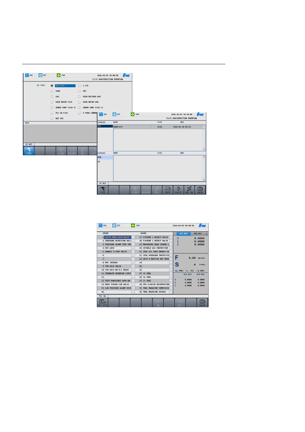
Press Set → PLC SW to enter the PLC Switch function interface, where
you may conduct operation based on bit for specified P parameters. See
the figure below:
Interface operation description
Up, Down, Left, Right keys: to move the position of the cursor.
125
8. Diagnosis
Enter: define the value of the
current status is ON, set it to OFF; if the current status is OFF, then set
position where the cursor is. If the
it to ON.
Menu operation description
SET EFF: This is used to protect the
ON and OFF menus. Only after you
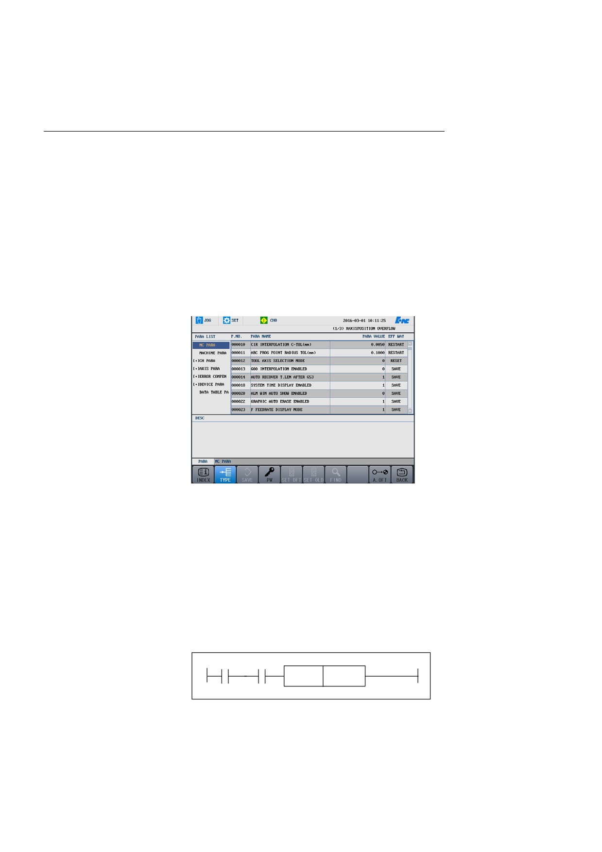
The settings are saved in the specified user P parameter. As shown in the
press the SET EFF menu, can the
figure below, the parameter 196 in this example is specified by the
operations on ON/OFF be valid.
PLCSW.STR file.
ON: Set the position where the
cursor is to ON.
OFF: Set the position where the
cursor is to OFF.
8.4.4 Manually Call Subprograms
Operation procedure
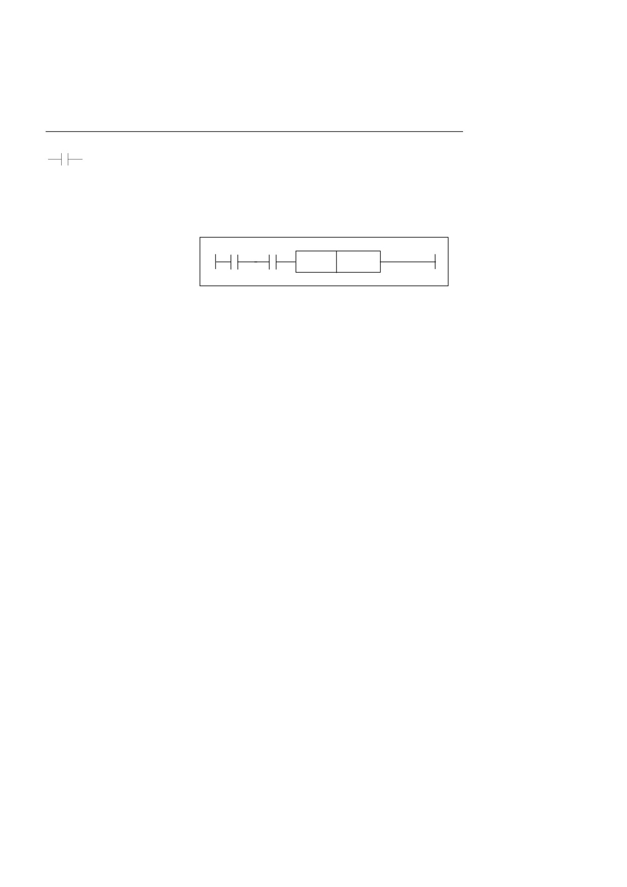
Create a ladder graph in the PLC as below:
F2564.0 Trigger signal
EVENT
100
Auto
126
8. Diagnosis
100: indicates the program name O100
: indicates the external
input signal to call subprograms
Attention
In this function, the system is in the auto mode and requires a trigger
signal.
Example
F2564.0
X484.5
EVENT
100
Auto
When the input signal X484.5 is valid, press the Start button to call the
O100 subprogram.
127
8. Diagnosis
8.5 Input and Output
Operation procedure
1.
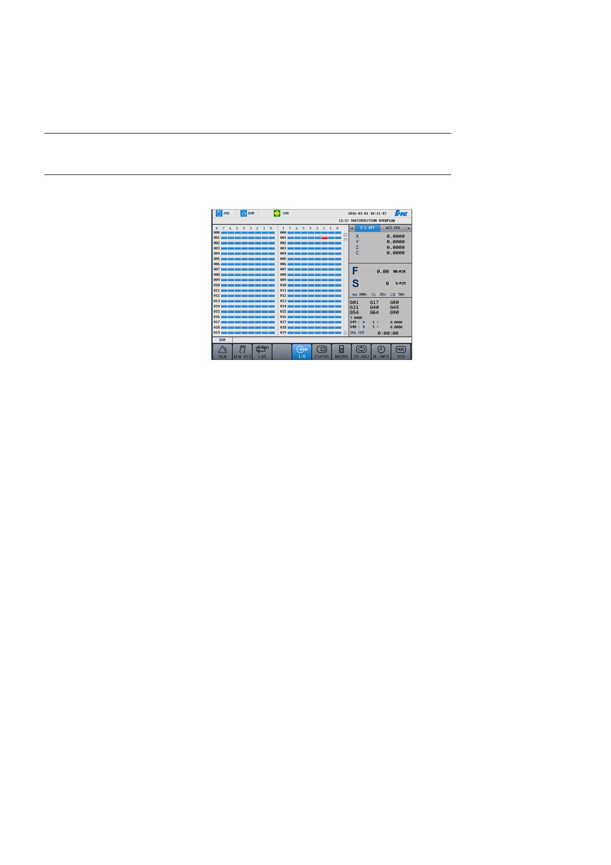
Press Dgn → I/O.
2.
Use the PgUp and PgDn keys to view the X or Y register status.
128
8. Diagnosis
8.6 Status Display
Operation procedure
1.
Press Dgn → STATUS.
2.
Use ▲ and ▼ to select the register type to view.
y X: input from the machine to PMC
y Y: output from the PMC to machine
y F: output from the CNC to PMC
y G: input from the PMC to CNC
y R: intermediate relay status display
y B: breakpoint data display
3.
Press PgUp and PgDn to browse screen up and down.
4.
Press the "Binary", "Decimal" or "Hexadecimal" key to view the
value of the register.
5.
Press FIND to search for a register value.
Attention
You may press the functional keys or shortcut keys to view the F
register and G register individually.
- System (Alt+S)
- Channel (Alt+C)
- Axis (Alt+A)
You may edit the B register.
129
8. Diagnosis
8.7 Macro Variables
Macro variables
HNC-818 CNC system provides you with the macro function similar to
high-level language. You may use variables to conduct arithmetic
operation, logical operation, and combined function operations. In
addition, the macro program provides cycle statement, branch statement,
and subprogram calling statements, which makes it easy to create
complex machining programs and avoids complicated calculation that
required in manual programming.
1.
Press Dgn → MACRO to view system macro variables.
2.
Press FIND, enter a macro variable number, and press Enter to
search for the macro variable.
Attention
1.
For detailed information about each macro variable, see section 13
in this user manual.
2.
The macro variables' value ranges from
-2147483648 to
2147483648.
User macro
1.
Press Set
→ PARA → DT MGT → TYPE → Customized
Configuration File.
2.
Press WD ST →USB, select a customized configuration file, press
LOAD to load the file.
3.
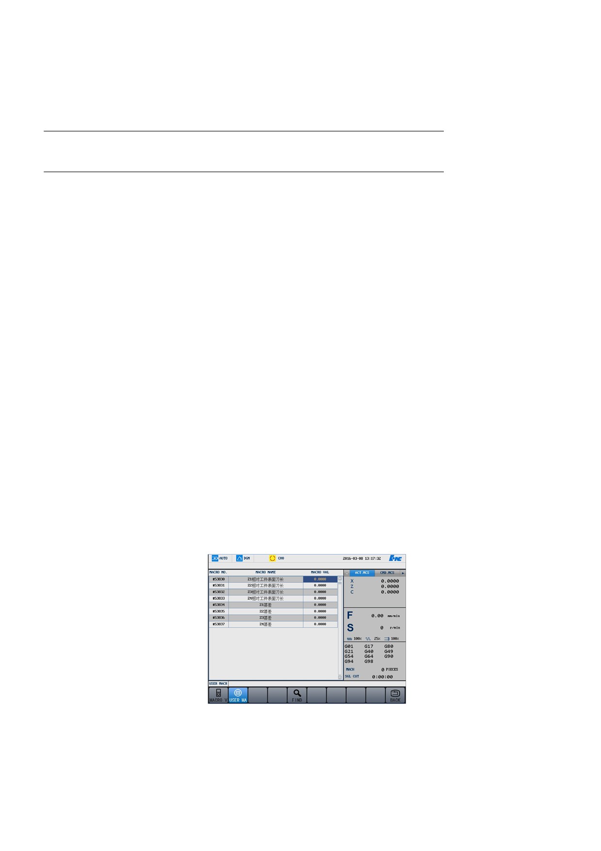
Press Dgn → MACRO → USER MA. The system displays the
macro variable numbers, names, and values.
130
8. Diagnosis
4.
Move the cursor to select a macro variable value, press Enter to
modify the value.
5.
You may create macro programs as required.
131
8. Diagnosis
8.8 Servo Adjustment
8.8.1 Speed Loop
Auto load of G codes
2.
If you enter the SV ADJ interface in the auto mode, the system will
automatically load the test G code. A message is displayed to
prompt you that the test code is loaded and they may press the Start
button to start sampling.
3.
If you enter the SV ADJ interface in the manual mode, you need to
change it to the auto mode, and press the Reset button to load the G
code.
4.
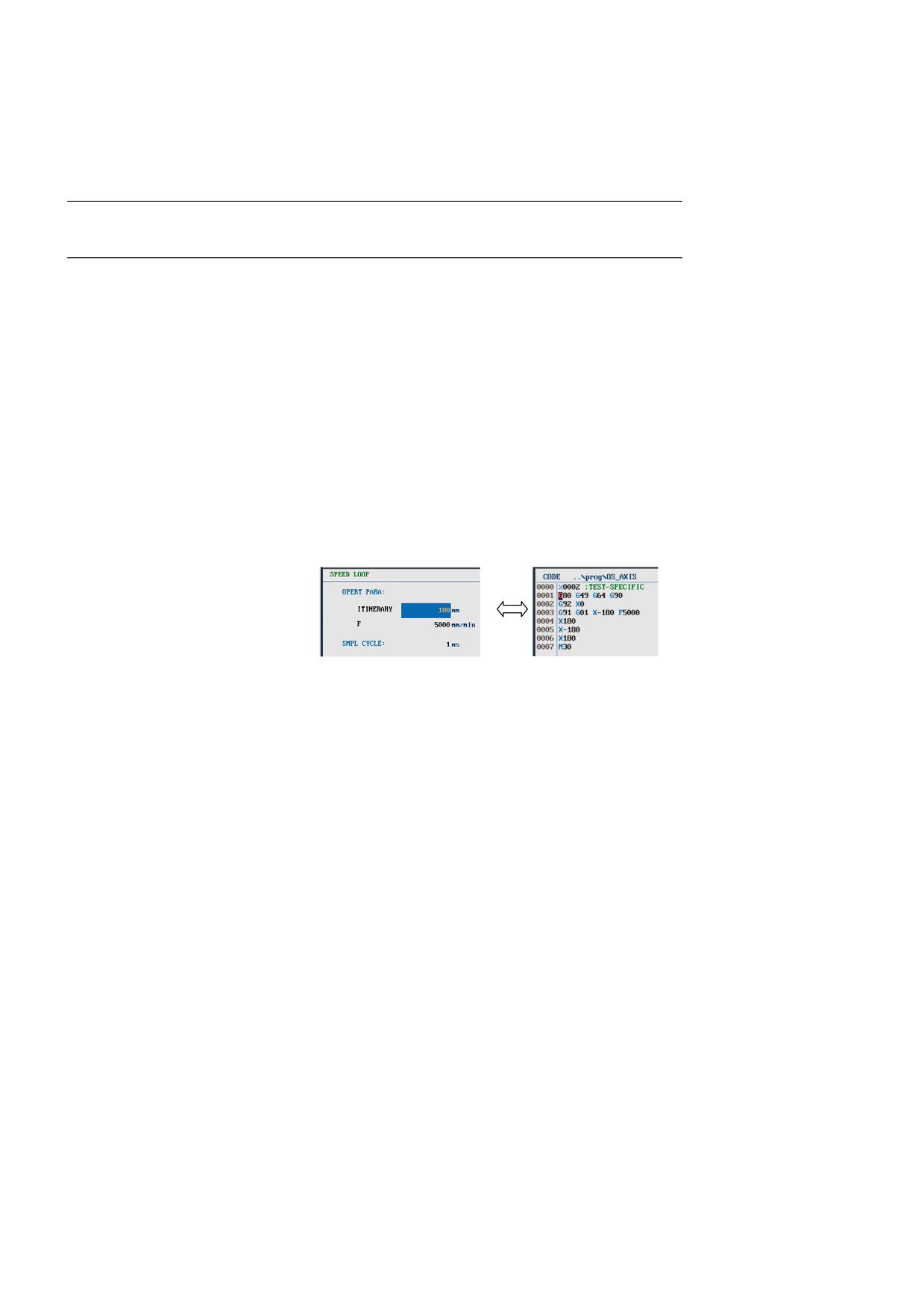
If you need to modify the G code, you may press Set to modify the
G code, press CODE to browse the G code (The settings interface
corresponds to the CODE interface.).
5.
You may press Alt+ direction keys (+/-) to modify the test axis.
Note: You need to manually move the machine to a safe position
before start sampling.
1.
Press Dgn → SV ADJ.
Sampling
1.
Press Dgn →SV ADJ, move the cursor to select SPEED LOOP.
2.
In the manual mode, move the machine to a safe position, switch to
the auto mode, press Reset to load the testing G code, and press
Start to start measurement.
3.
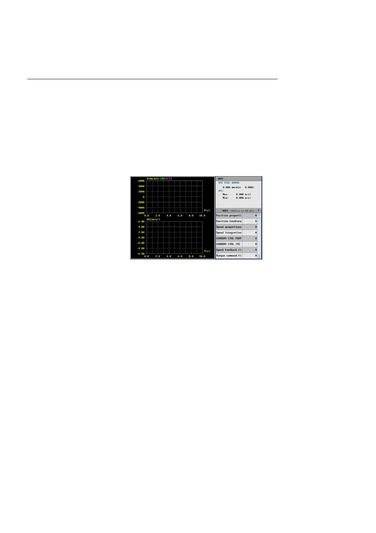
The measurement waveform of the speed, acceleration speed, and
the speed fluctuation range is obtained after the measurement. See
the figure below:
132
8. Diagnosis
4.
Press the cursor key "→" to adjust the parameter of each axis, e.g.
"SPEED PROPORTIONAL GAIN" and "SPD FEEDBACK
FILTER".
5.
Press Alt + direction key (+/-) to select an axis for settings.
6.
You may adjust parameters, conduct measurement for multiple
times to meet the expected effects.
8.8.2 Position Loop
Auto load of G codes
1.
Press Dgn →SV ADJ.
2.
If you enter the SV ADJ interface in the auto mode, the system will
automatically load the test G code. A message is displayed to
prompt you that the test code is loaded and they may press the Start
button to start sampling.
3.
If you enter the SV ADJ interface in the manual mode, you need to
change it to the auto mode, and press the Reset button to load the G
code.
4.
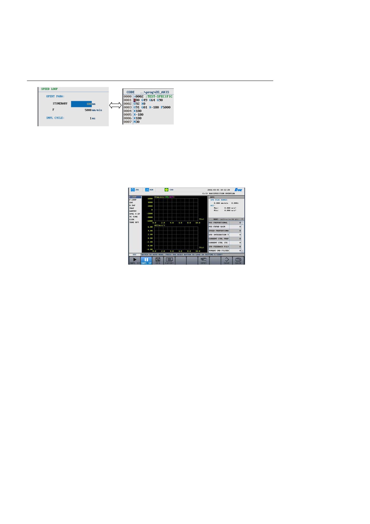
If you need to modify the G code, you may press Set to modify the
G code, press CODE to browse the G code (The settings interface
corresponds to the CODE interface.).
133
8. Diagnosis
N
y move the machine to a safe position
before start sampling.
5.
You may press Alt + direction
keys
(+/-) to modify the test
Sampling
cursor to select POS LOOP.
2.
In the manual mode, move the machine to a safe position, switch to
the auto mode, press Reset to load the testing G code, and press
Start to start measurement.
3.
Press the cursor key "→" to adjust the parameter of each axis, e.g.
"SPEED PROPORTIONAL GAIN" and "SPD FEEDBACK
FILTER".
4.
Press Alt + direction key (+/-) to select an axis for settings.
5.
You may adjust parameters, conduct measurement for multiple
times to meet the expected effects.
1.
Press Dgn →SV ADJ, move the
8.8.3 Circularity Test
Auto load of G codes
134
8. Diagnosis
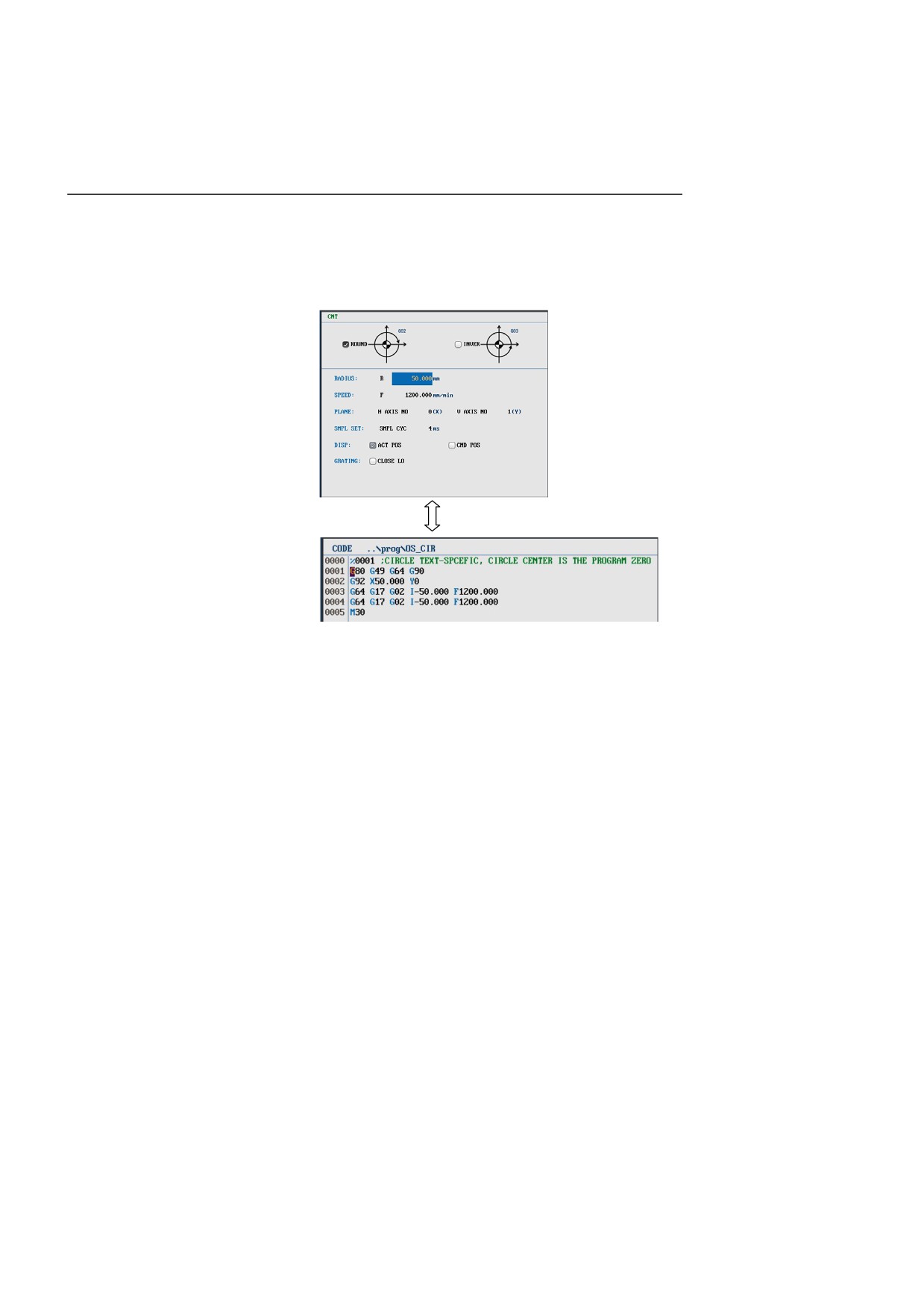
1.
Press Dgn →SV ADJ.
2.
If you enter the SV ADJ
interface in the auto mode, the
system will automatically load
the test G code. A message is
displayed to prompt you that the
test code is loaded and they may
press the Start button to start
sampling.
3.
If you enter the SV ADJ
interface in the manual mode,
you need to change it to the
auto mode, and press the Reset
button to load the testing G
code.
4.
If you need to modify the G
codes, you may modify the
parameters on the interface to
modify the G codes. You may
view the modified G codes in
the CODE interface.
5.
You may press Alt+ direction keys (+/-) to modify the test axis.
Note: You need to manually move the machine to a safe position
before start sampling.
Sampling
1.
Press Dgn →SV ADJ, move the cursor to select CNT.
135
8. Diagnosis
2.
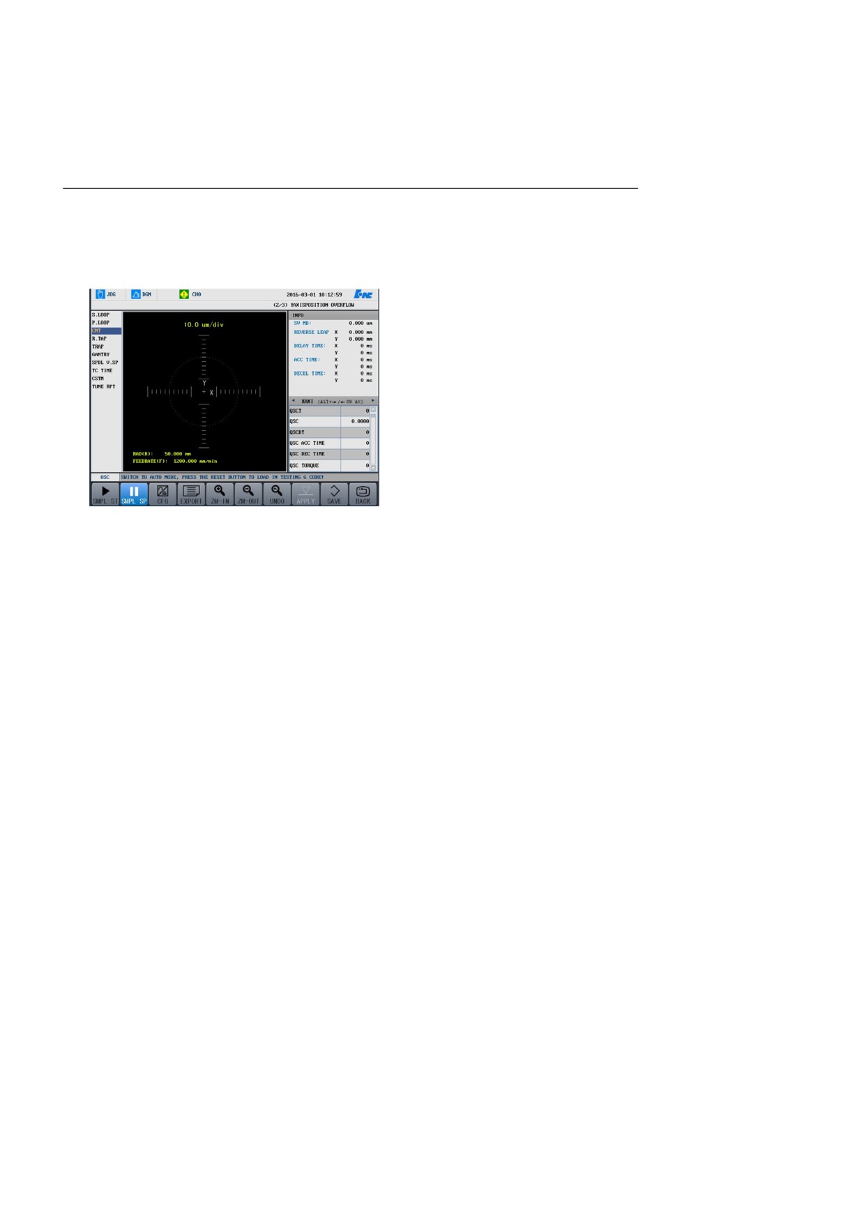
Press SMPL ST and Start to
start the measurement. The
result is shown in the figure
below:
5.
You may adjust parameters, conduct measurement for multiple
times to meet the expected effects.
6.
Press APPLY, and input the compensation parameters
automatically calculated by the system to the parameter list.
7.
Press Dgn →SV ADJ → ZM IN to zoom in the graph.
3.
Press the cursor key "→" to
8.
Press Dgn →SV ADJ → ZM OUT to zoom out the graph.
adjust the parameter of each
9.
Press Dgn →SV ADJ → UNDO to restore the graph.
axis.
4.
Press Alt + direction key (+/-)
to select an axis for settings.
8.8.4 Rigid Tapping
Auto load of G codes
1.
Press Dgn →SV ADJ.
2.
If you enter the SV ADJ interface in the auto mode, the system will
automatically load the test G code. A message is displayed to
prompt you that the test code is loaded and you may press the Start
button to start sampling.
136
8. Diagnosis
3.
If you enter the SV ADJ
interface in the manual mode,
you need to change it to the
auto mode, and press the Reset
button to load the testing G
code.
4.
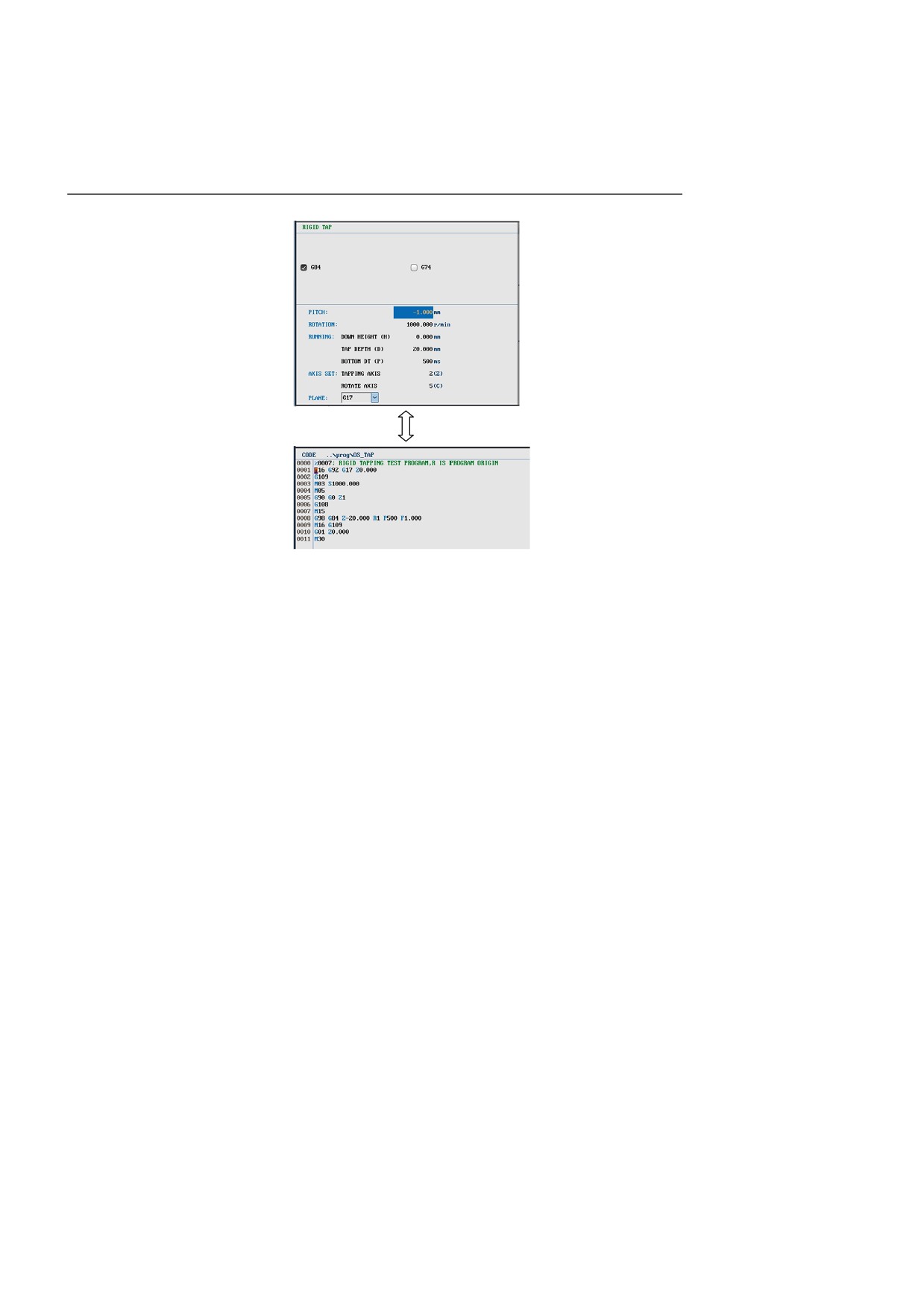
Press Set to enter the G code
settings interface. You may
modify the parameters on the
interface to modify the G codes.
You may view the modified G
codes in the CODE interface.
5.
You may press Alt+ direction keys (+/-) to modify the test axis.
Note: You need to manually move the machine to a safe position
before start sampling.
Sampling
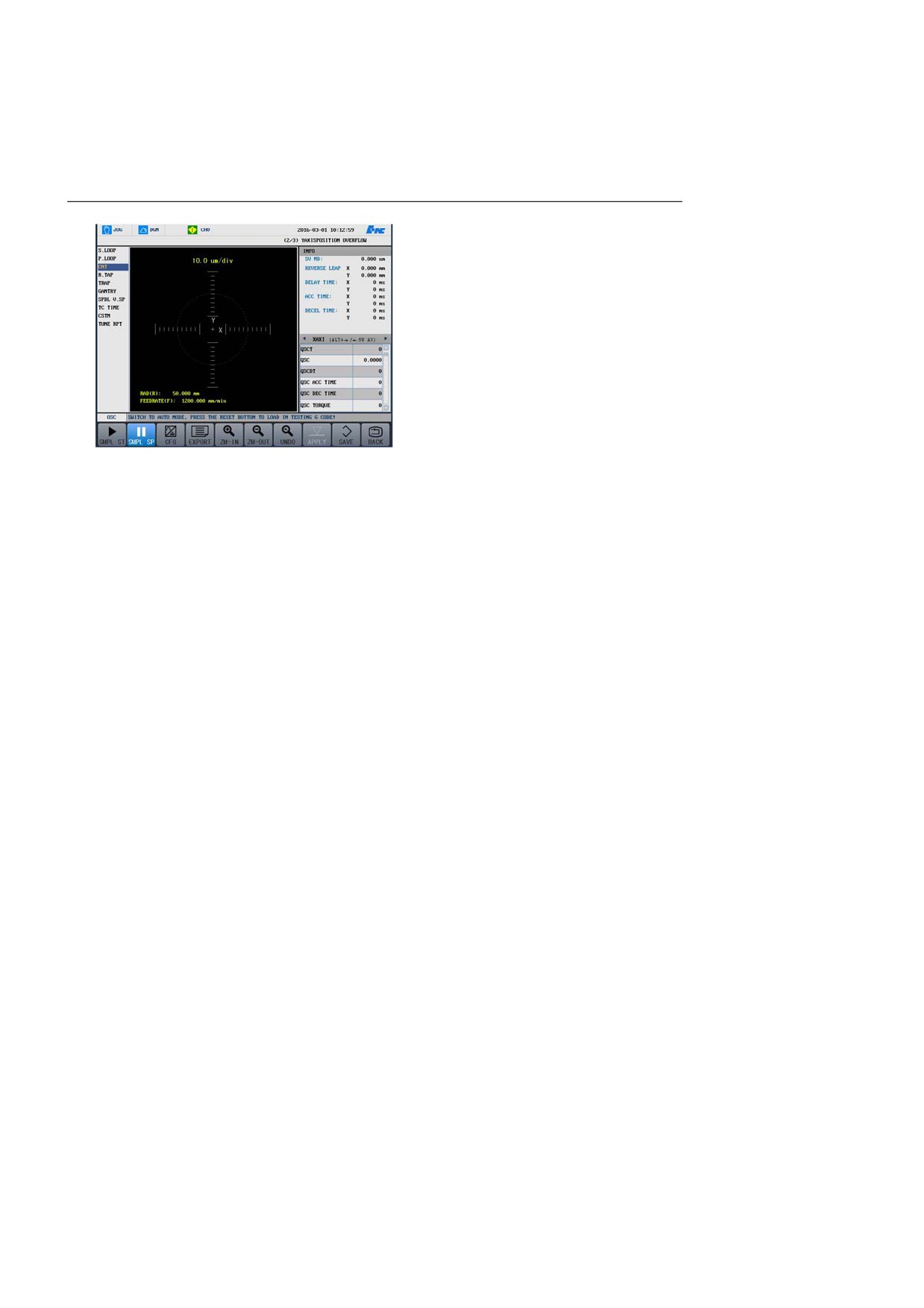
1.
Press Dgn →SV ADJ, move the cursor to select POS LOOP.
2.
In the manual mode, move the machine to a safe position, switch to
the auto mode, press Reset to load the testing G code, and press
Start to start measurement.
137
8. Diagnosis
3.
Press the cursor key "→" to adjust the parameter of each axis, e.g.
"SPEED PROPORTIONAL GAIN" and "SPD FEEDBACK
FILTER".
4.
Press Alt + direction key (+/-) to select an axis for settings.
5.
You may adjust parameters, conduct measurement for multiple
times to meet the expected effects.
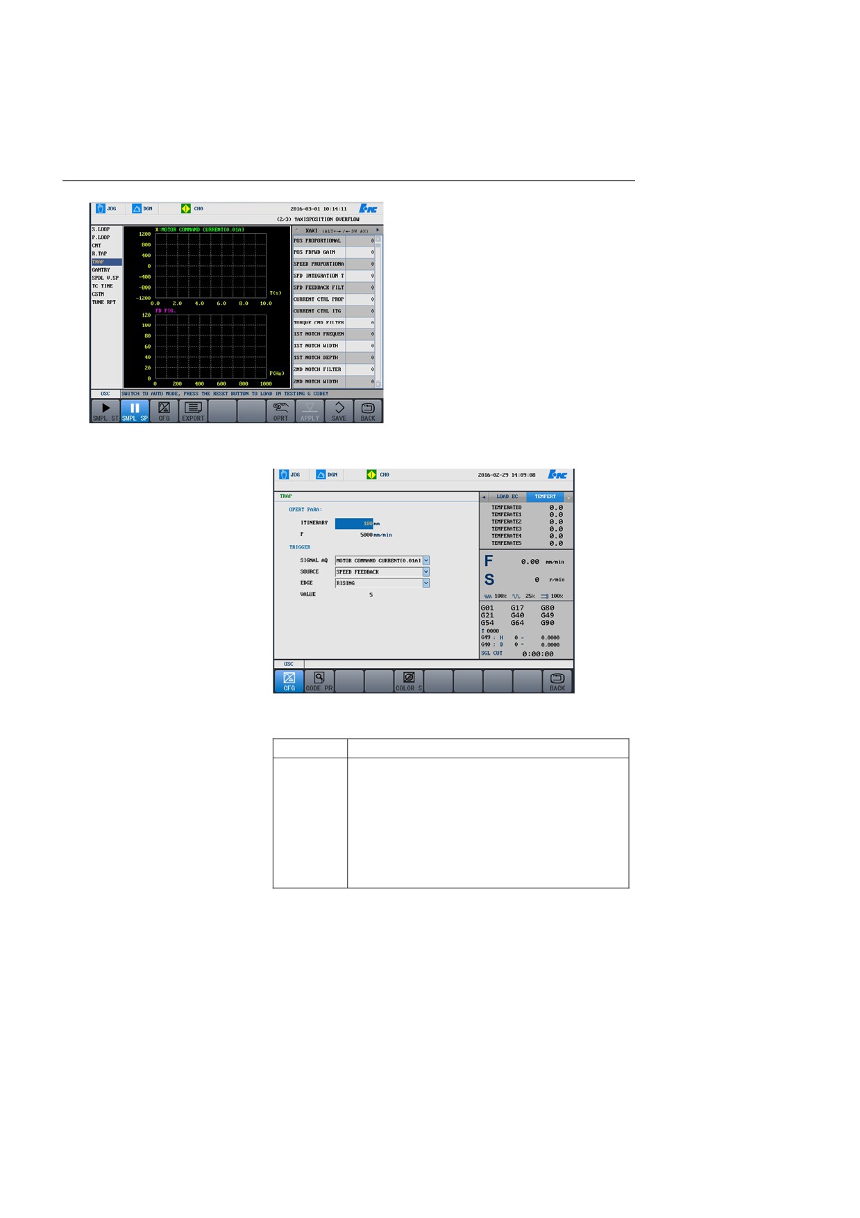
8.8.5 Trap
Function Description
loop gain and reduce speed fluctuation.
The system provides trap function,
which is mainly used in the
following scenarios:
1.
Increase the speed loop gain:
Select a speed to move the
machine. After increasing the
speed loop gain, if machine
vibration occurs, then users may
use the trap 1 to eliminate the
vibration. If users continue to
increase the gain, and the
2.
High and low speed optimization: Firstly, conduct debugging at low
vibration occurs, then users may
speed (for example F2000), increase the gain and add trap
1.
use the trap 2 to eliminate the
Thereafter do not increase the gain, and change to the high-speed
vibration. In this mode, it is
(e.g. F40000) mode to conduct debugging, to check whether
recommended to use the
machine vibration or whistle occurs. If there is vibration or whistle,
processing speed for debugging,
use trap 2 to eliminate it.
in order to maximize the speed
138
8. Diagnosis
Settings interface
Usage
Description
Select a speed to move the machine. After increasing
the speed loop gain, if machine vibration occurs, then
Increase the
you may use the trap 1 to eliminate the vibration. If
speed loop
you continue to increase the gain, and the vibration
gain
occurs, then you may use the trap 2 to eliminate the
vibration. In this mode, the speed loop can be
increased to about 2000.
139
8. Diagnosis
whether machine vibration or whistle occurs. If there
is vibration or whistle, use trap 2 to eliminate it.
If two traps are configured and there is still a little vibration or whistle,
you may:
1.
Increase the speed integral time constant properly, but the value
should not exceed 3.
Firstly, conduct debuggin 2. t l Decrease the speed loop gain a little.
High and
F2000), increase the gain and add trap 1. Thereafter
low speed
do not increase the gain, and change to the high-speed
optimization
(e.g. F40000) mode to conduct debugging, to check
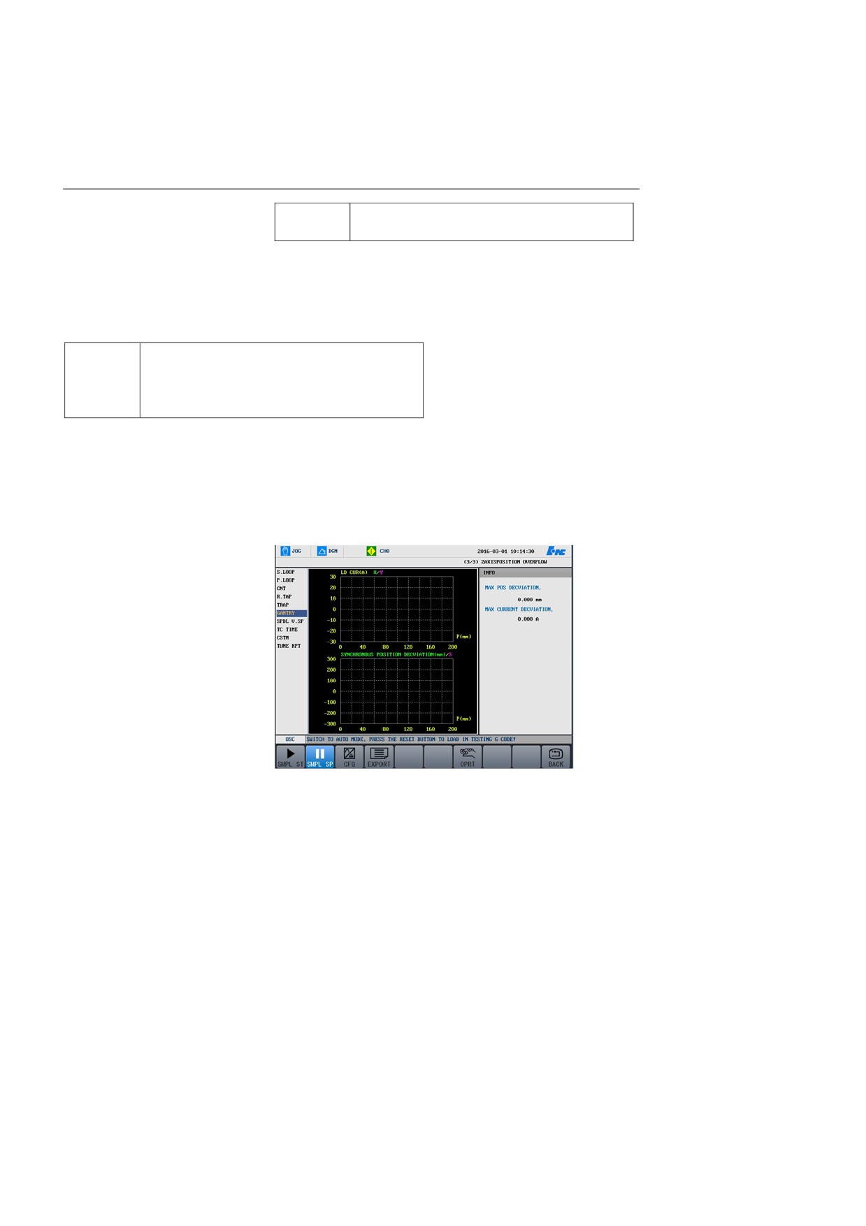
8.8.6 Gantry Synchronization Axis
This function is mainly used for collecting the load currents of two
synchronization axes, as well as the position deviation and the current
deviation of the synchronization axes. See the figure below:
The system automatically generates G codes based on the data
(synchronization axis number, travel, speed) defined in the settings
interface. In the auto mode, run the G code to collect data. In the manual
mode, press the SMPL ST button to manually move the axis to collect
data. After the data collection is completed, the maximum positional
deviation and current deviation values of the synchronization axis will be
displayed in the right pane.
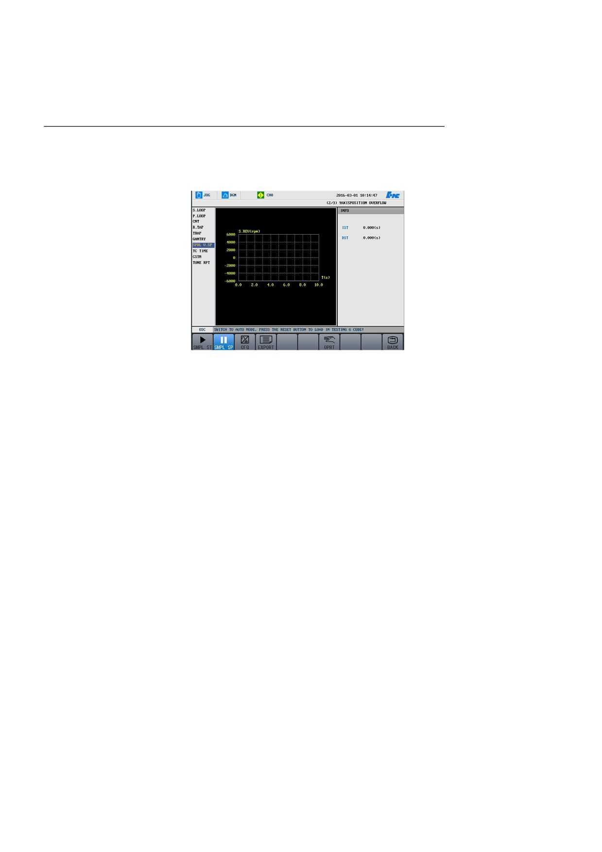
8.8.7 Spindle Acceleration and Deceleration Speed
140
8. Diagnosis
This function is used to test the time that the spindle speed increases
from 0 to the specified speed, and the time that the spindle speed
decreases from the specified speed to 0. See the figure below:
In the auto mode, enter the spindle acceleration and deceleration speed
configuration interface. Set the spindle speed, and the system will
automatically generate simple G-codes, e.g. "M3 S1000 M5 M30". After
running the G code, the system automatically calculates the spindle
acceleration and deceleration speed with specified rotation, and output
the results in the right information pane.
Attention
1.
Make sure the Spindle override adjustment button is in the 100%
position; otherwise, the calculated time may be inaccurate.
2.
Please set the value of the spindle parameter "SPEED ARRIVAL
RANGE" to 0; otherwise, the calculated result may be inaccurate.
141
8. Diagnosis
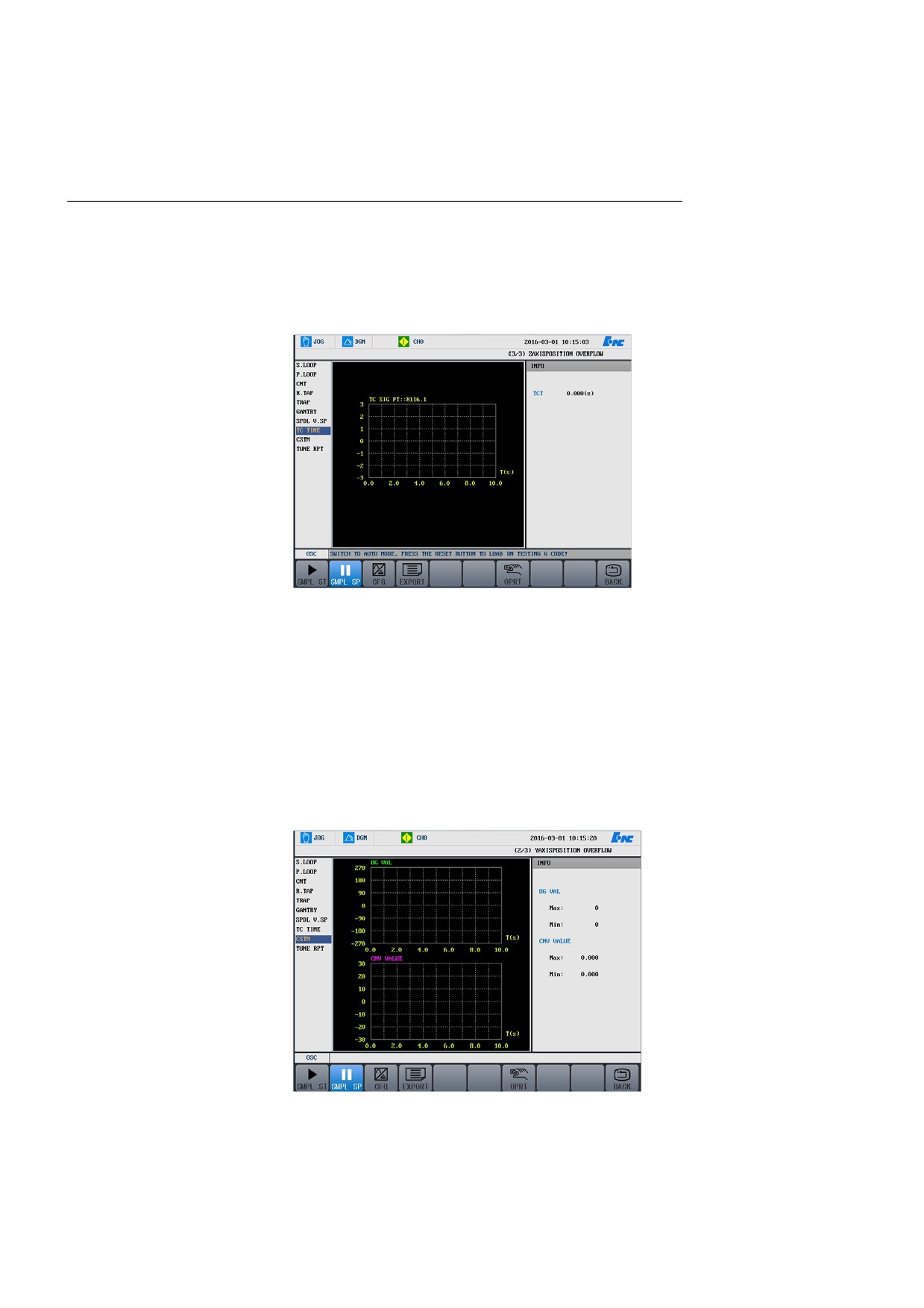
8.8.8 Tool Change Time
This function is used to collect tool change signal and calculate the time
required for tool change. See the figure below:
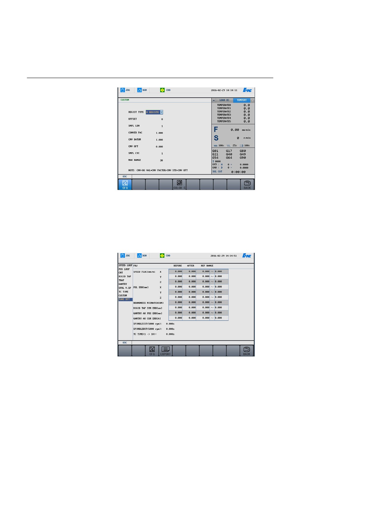
8.8.9 Customized Collection
This function can be uses to capture the value of any register. Users can
customize the conversion coefficient, conversion standard and offset of
the register value. According to the formula "conversion value = original
value * conversion coefficient/conversion standard + offset", users may
convert the register value into real values, such as voltage, current,
position, temperature, and so on. The value collection and configuration
interface is as below:
142
8. Diagnosis
8.8.10 Tuning Reports
The function is used to record the KPIs before and after tuning, establish
tuning files, and export the file for archiving. See the figure below:
Attention
When using the servo adjustment function for tuning, make sure the feed
override and Spindle override adjustment button is in the 100% position;
otherwise, the recorded data may be inaccurate.
143
8. Diagnosis
8.8.11 Operation and Settings
You may zoom in, zoom out, change colors for the sampling diagram
mentioned above.
Graph related operations
You may press Dgn → SV ADJ to view the graph.
-
PgUp and PgDn: select a mode to browse the graph: JOINT,
GRAPH 1, GRAPH 2
-
Alt+↑ or Alt+↓: In the combined mode, switch between
GRAPH 1 and GRAPH 2
-
Zoom in horizontal axis: Zoom in the horizontal axis
-
Zoom out horizontal axis: Zoom out the horizontal axis
-
Zoom in vertical axis: Zoom in the vertical axis
-
Zoom out vertical axis: Zoom out the vertical axis
-
Zoom in windows: Zoom in the selected area in the graph
-
Zoom out windows: Zoom out the selected area in the graph
-
UNDO: restore the original legend of the graph
-
Enter: Zoom in the graph in the selected area
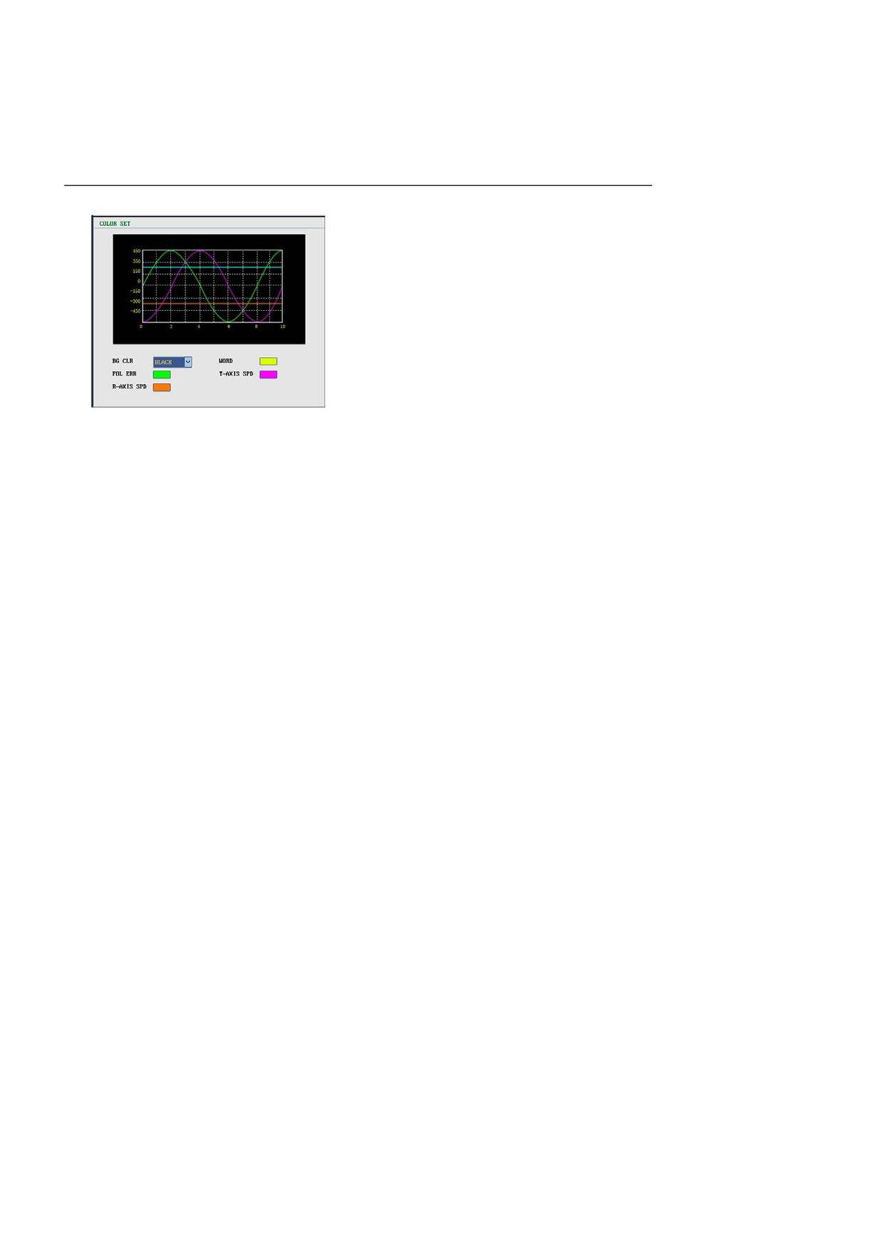
Color settings
You may change the color of the graph displayed in the system.
1.
Press Dgn → SV ADJ → Set → COLOR SET. The figure below
shows the color settings interface for the speed loop graph:
144
8. Diagnosis
2.
Press Enter to select a background color.
3.
Press Enter to confirm the settings. The system text color,
command speed color, actual speed color, acceleration speed color
will be changed after the background color is changed.
Export
Press Dgn →SV ADJ →EXPORT to export the sampling data.
Save
Press Dgn →SV ADJ→ SAVE to save the parameter settings.
145
8. Diagnosis
8.9 Machining Information
View
Press Dgn → M. INFO → STATISTICS to view the machining
information.
Pre-define
This function is available only to the machine manufacturer, CNC
manufacturer, and administrator.
1.
Press Dgn
→M. INFO → SET to define the machining
information.
2.
Move the cursor set to select the item to set.
3.
Press Enter.
Clear
This function is available only to the machine manufacturer, CNC
manufacturer, and administrator.
Press Dgn
→M. INFO→ CLEAR to clear all current machining
statistics information.
Note: After modifying the time, users need to manually clear the
machining statistics time related information; otherwise, wrong statistics
data may be displayed.
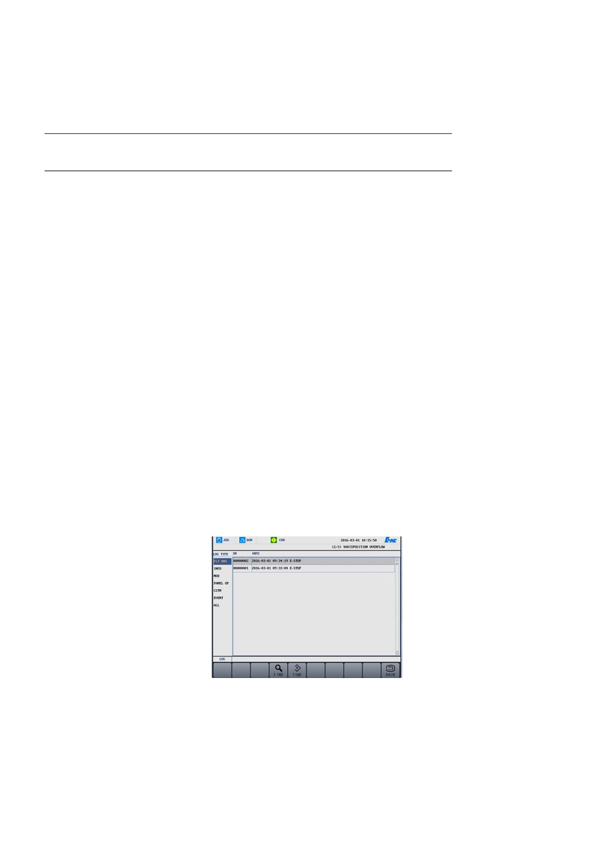
Log
1.
Press Dgn →M. INFO → LOG to display system debugging
information.
146
8. Diagnosis
2.
Move the cursor to select a log type.
3.
Press EXPORT to export corresponding log files.
4.
You may press the chronological order key to display the log files in
the chronological order.
147
8. Diagnosis
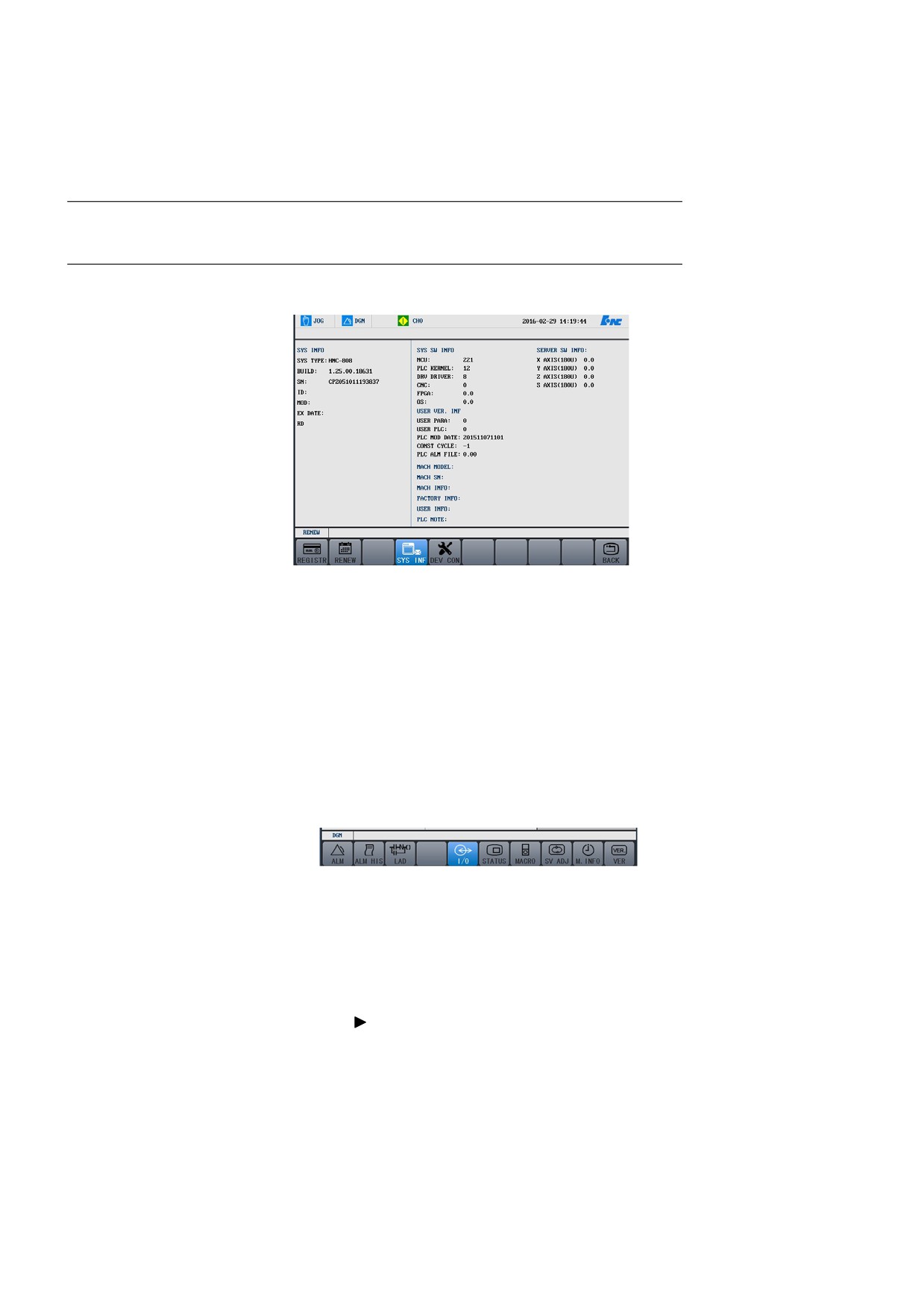
8.10 Version
Query version
You may Press Dgn →VER to view the system version information.
Register
Note: The registration expiration alarm is reported 12 hours after the real
expiration.
1.
As shown in the figure above, the message "REGISTR" is
highlighted on the interface. Users may press Enter, select USB,
Renew
load the registration file, cut off the power, and restart the system.
2.
As shown in the figure above, the message
“RENEW" is
highlighted on the interface. Users may press Enter, and enter the
renew code.
Note: Pay attention to the capitalization and hyphens.
3.
Press Enter again.
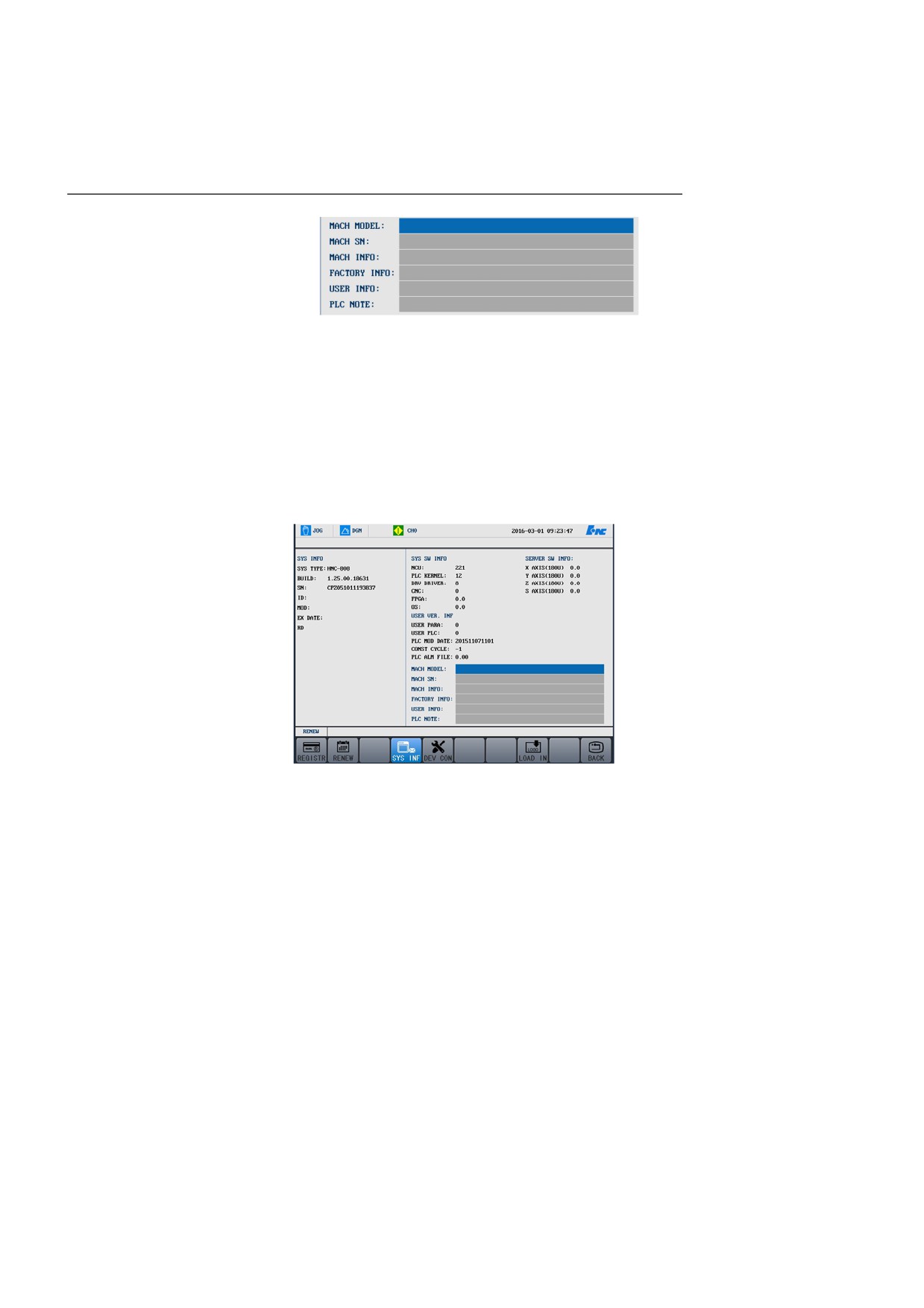
Set machine information
Note: This function is available only to the machine manufacturer,
CNC manufacturer, and administrator.
1.
Press
to move the cursor to the MACH MODEL part.
148
8. Diagnosis
2.
Press Enter to input information about machine model,
manufacturer, etc.
PLC version information
This function is used to record the PLC modification time and
information.
After debugging personnel modify the PLC, the PLC modification time
will be automatically recorded, shown in the figure below. In addition,
the PLC modification information can be input in the PLC NOTE, e.g.
Modified by. A maximum of eight characters can be input.
149
9. User Operation and Maintenance Information
9 User Operation and Maintenance Information
This chapter includes the following sections:
-
Environmental Requirements
-
Grounding
-
Power Conditions
-
Clean Fan Filter
-
Operation After Being Left Unused
150
9. User Operation and Maintenance Information
9.1 Environmental Requirements
The table below describes the environmental requirements of HNC-818:
Items
Description
Working
0 to +45, non-freezing
temperature (ºC)
Temperature change
< 1.1 ºC/min
Relative humidity
90% RH or lower (non-condensable)
Normal: 75% or lower
Short period (within a month): Max. 95%
Storage temperature
-20 to +60, non-freezing
(ºC)
Storage humidity
Non-condensable
Surrounding
Indoor (non-exposed to sun), anti-sepsis,
environment
anti-burning, anti-fog, anti-dust
Height
A maximum of 1000 (2000) meters above
sea level
Vibration (m/s)
10 to 60 Hz: 5.9 (0.6G) or lower
151
9. User Operation and Maintenance Information
9.2 Grounding
Correct grounding is critical for the numerical control unit and other
electrical devices. Correct grounding may:
-
Protect operators from electric shock or injury caused by no
grounding or incorrect grounding.
-
Protect the electrical devices from inductive interference which may
lead to errors or unexpected results.
When installing machine, reliable grounding must be provided. The
neutral line in the power grid cannot be used as the grounding line,
otherwise, it may cause device damage or abnormal operation, or even
casualties.
152
9. User Operation and Maintenance Information
9.3 Power Conditions
The power supply of HNC-818 turning system is provided by the
electric cabinet. For more information about machine power supply, see
the installation guide of the machine.
153
9. User Operation and Maintenance Information
9.4 Clean Fan Filter
Filters are used on cooling fans to prevent dust from entering into
devices, which are designed at the inlet and outlet.
However, it may prevent adequate cooling if the filters become clogged,
and thus cause improper device running. It is recommended to clean the
filters every three months. In dusty environments, clean the filters more
often.
154
9. User Operation and Maintenance Information
9.5 Operations After Being Left Unused
After a long period of being left unused, numerical control devices
should be cleaned and dried, so should the wiring and ground
connections. Once power is resumed after being left unused, observe the
operation for several hours to make sure there is no problem.
155