HSD3 Series AC Servo Drive. User's Manual (Version: 3.1.14) - page 9
 

  Index      Manuals     HSD3 Series AC Servo Drive. User's Manual (Version: 3.1.14)


Search            copyright infringement  


Content      ..     7      8      9      10     ..


HSD3 Series AC Servo Drive. User's Manual (Version: 3.1.14) - page 9


- 132 -

Reference

number

Name

Range

Unit

Factory value

Effective

Remarks

Pn513

Output signal selection 0

----

--

0001

Restart

A axis: 0001
b axis: 0004

Pn514

Input signal selection 1

---

--

0060

Restart

A axis: 0000
b axis: 0000

Pn516

Input signal selection 2

---

--

0211

Restart

A axis: 0011
b axis: 0022

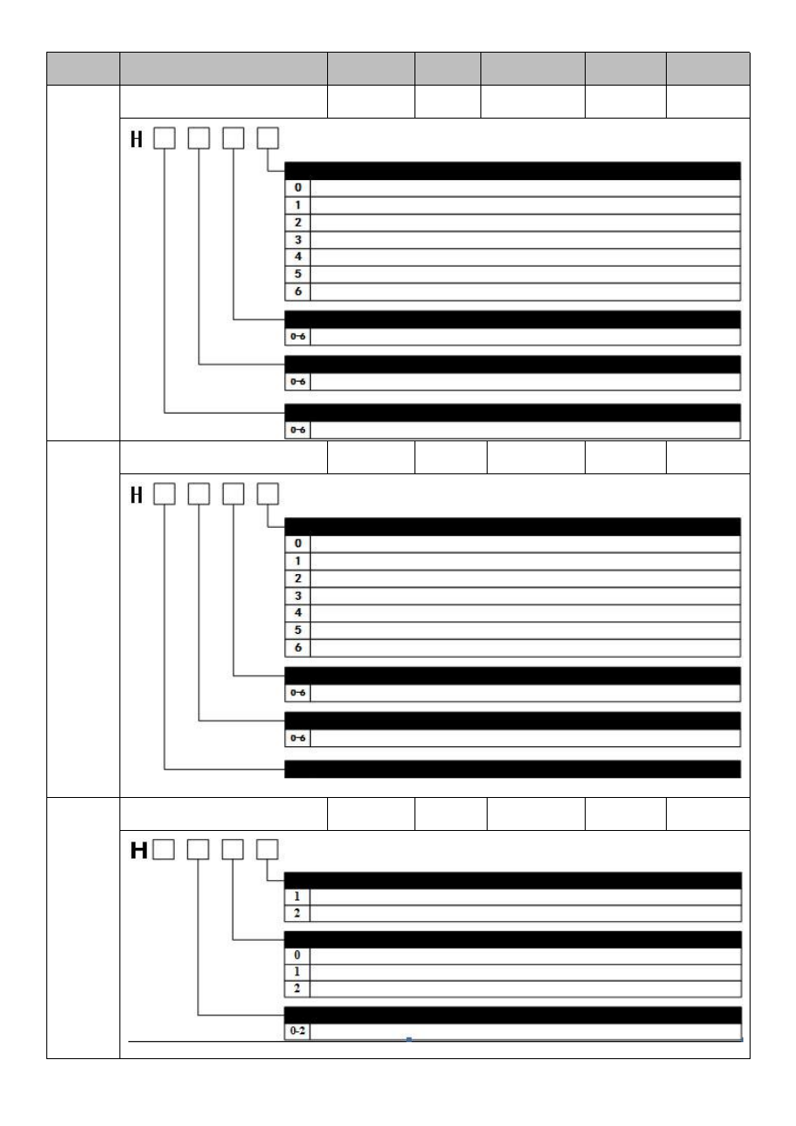
The 3rd bit

The 2nd bit

The 1st bit

The 0 bit

Servo alarm signal allocation (ALM)

Invalid (don’t use the signal)
Output the above signal through CN1-OUT1 output terminal
Output the above signal through CN1-OUT2 output terminal
Output the above signal through CN1-OUT3 output terminal
Output the above signal through CN1-OUT4 output terminal
Output the above signal through CN1-OUT5 output terminal
Output the above signal through CN1-OUT6 output terminal

Position completion signal allocation (/COIN) / same speed detection signal allocation (/V-CMP)

Servo ready detection signal allocation (/S-RDY)

Same as above

Same as above

Motor multi rotation detection signal allocation (/TGON)

Same as above

The 3rd bit

The 2nd bit

The 1st bit

The 0 bit

Torque limit output signal allocation (/CLT)

Invalid (don’t use the signal)
Output the above signal through CN1-OUT1 output terminal
Output the above signal through CN1-OUT2 output terminal
Output the above signal through CN1-OUT3 output terminal
Output the above signal through CN1-OUT4 output terminal
Output the above signal through CN1-OUT5 output terminal
Output the above signal through CN1-OUT6 output terminal

Brake signal allocation (/BK)

Same as above

Same as above

Encoder origin signal allocation (/PGC)

The signal allocation of pulse input port

Reserved by the manufacturer

Analog speed command VREF signal allocation

Use the input signal of APULS
Use the input signal of bPULS

Not allocated
Use the input signal of ANA1
Use the input signal of ANA2

TREF signal allocation of analog torque command

Same as above

The 3rd bit

The 2nd bit

The 1st bit

The 0 bit

- 133 -

Reference

number

Name

Range

Unit

Factory value

Effective

Remarks

Pn517

Input port filtering time

0 – 100

0.1ms

1

Immediately

Pn518

Alarm input port filtering time

0 - 3

0.1ms

1

Immediately

Pn519

Input port signal effective electrical

level selection 0

----

--

0000

Immediately

Pn520

Input port signal effective electrical

level selection 1

----

--

0000

Immediately

Pn521

Output

port

signal

negation

selection 0

---

--

0000

Immediately

The 3rd bit

The 2nd bit

The 1st bit

The 0 bit

CN1-IN1 input effective electrical level selection

Same as above

Motor multi rotation detection signal allocation (/TGON)

CN1-IN2 input effective the electrical level selection

CN1-IN3 input effective the electrical level selection

CN1-IN4 input effective the electrical level selection

Same as above

Same as above

It is valid when input signal ON (L electrical level)
It is valid when input signal OFF (H electrical level)

CN1-OUT1 output negation selection

No negation
Negation

Same as above

The 3rd bit

The 2nd bit

The 1st bit

The 0 bit

CN1-IN6 input effective electrical level selection

CN1-IN7 input effective electrical level selection

CN1-IN8 input effective the electrical level selection

It is valid when input signal ON (L electrical level)
It is valid when input signal OFF (H electrical level)

Same as above

Same as above

Same as above

CN1-IN5 input effective electrical level selection

CN1-OUT2 output negation selection

CN1-OUT3 output negation selection

CN1-OUT4 output negation selection

Same as above

Same as above

The 3rd bit

The 2nd bit

The 1st bit

The 0 bit

- 134 -

Reference

number

Name

Range

Unit

Factory

value

Effective

Remarks

Pn522

Output port signal negation selection 1

----

--

0000

Immediately

Pn523

Offset pulse overflow electrical level

1 - 1073741823

Command pulse

524288

Immediately

Pn526

Positioning completed time

0 - 60000

0.1ms

500

Immediately

Pn527

Analog input speed command filtering time

0 - 32768

0.1ms

0

Immediately

Pn528

Analog input torque command filtering time

0 - 32768

0.1ms

0

Immediately

Pn600

Axis address(Modbus/CANopen/USB)

1 - 127

--

1

Restart

B axis: 2

Pn601

Modbus

communication

parameter

selection switch

----

--

0051

Restart

Pn603

CANopen

communication

parameter

selection switch

----

--

0004

Restart

The 3rd bit

The 2nd bit

The 1st bit The 0 bit

The 3rd bit

The 2nd bit

The 1st bit The 0 bit

The 3rd bit

The 2nd bit

The 1st bit The 0 bit

CN1-OUT5 output negation selection

CN1-OUT6 output negation selection

Communication baud rate selection

Communication protocol selection

Reserved by the manufacturer

Reserved by the manufacturer

Reserved by the manufacturer

CAN Communication baud rate selection

CANopen communication enable switch

Modbus, ASCII Mode

Modbus, RTU Mode

Close CANopen communication

Enables CANopen communication

Same as above

Same as above

- 135 -

Reference

number

Name

Range

Unit

Factory

value

Effective

Remarks

Pn605

M2 communication parameter selection switch

----

--

0111

Restart

Pn606

M2 axis address

0000 - 00FE

--

0001

Restart

B axis: 0002

Pn605

Selection switch of M3 communication

parameter

---

--

0111

Restart

Pn606

M3 axis address

0000 - 00FE

0021

Restart

B axis: 0022

Pn605

EtherCAT Station address selection

0 - 1

0

Restart

B axis invalid

0

The setting value of PA60 parameter is the EtherCAT station address (Station alias)

1

The value (0004h) of SII area Ether CAT is the station address (Station alias)

Pn606

EtherCAT the station address

0000 ~ FFFF

0000

Restart

B axis invalid

4Mbps

(M-I)

4Mbps

(M-II)

17 bytes (M-II)

32 bytes (M-III)

32 bytes (M-II)

48 bytes (M-III)

Normal mode
Yaskawa mode

Reserved by the manufacturer

Parameter mode

Transmission byte setting

Communication speed setting

The 3rd bit

The 2nd bit

The 1st bit The 0 bit

Transmission byte setting

Normal mode
Yaskawa mode

17 bytes (M-II)

32 bytes (M-III)

32 bytes (M-II)

48 bytes (M-III)

Reserved by the manufacturer

Parameter mode

Reserved by the manufacturer

The 3rd bit

The 2nd bit

The 1st bit The 0 bit

- 136 -

Reference

number

Name

Range

Unit

Factory

value

Effective

Remarks

Pn610

No. 8 data group type

----

--

0

Restart

0: the data group is invalid

1: the absolute motion mode

2: the relative motion mode

Pn611

No. 8 group data group low position

-9999 - +9 999 The command

unit

0

Restart

Pn612

No. 8 group data group high position

-9999 - +9 999

10000 the

command unit

0

Restart

Pn613

No. 8 data group operating speed

0 - 6000

1rpm

100

Restart

Pn614

No. 8 data group step changing property

----

--

0000

Restart

Pn615

No. 8 data group step change 1 value

0 - 65535

--

0

Restart

-Unconditional: no transition condition value

- Delay: value 0...65535, the waiting time is 0...65535, and the unit time is ms

- Pulse edge: the value 0 identifies the rising edge

value 1 indicates the descent edge

value 2 indicates

the rising edge or the descending edge

Electrical level: value 3 indicates 1 electrical level

value 4 indicates 0 electrical level

Pn616

No. 8 data group step change 2 value

0 - 65535

--

0

Restart

-Unconditional: no transition condition value

- Delay: value 0...65535, the waiting time is 0...65535, and the unit time is ms

- Pulse edge: the value 0 identifies the rising edge

value 1 indicates the descent edge

value 2 indicates

the rising edge or the descending edge

Electrical level: value 3 indicates 1 electrical level

value 4 indicates 0 electrical level

Pn617

No. 8 data group subsequent data group

0 - 14

--

9

Restart

The 3rd bit

The 2nd bit

The 1st bit The 0 bit

Data group step change condition type 1

Pulse edge of signal input (/POS-SIEP)
Electrical level of signal input (/POS-SIEP)

The logical conditions between step change 1 and step change 2

Pulse edge of signal input (/POS-SIEP)
Electrical level of signal input (/POS-SIEP)

Connectionless
And (AND)
Or (OR)

Unconditional
Delay

Data group step change condition type 2

Unconditional
Delay

Step change transient mode

- 137 -

Reference

number

Name

Range

Unit

Factory

value

Effective

Remarks

Pn618

No. 9 data group type

---

--

0

Restart

0: the data group is invalid

1: the absolute motion mode

2: the relative motion mode

Pn619

No. 9 group data group low position

-9999 - +9 999

The

instruction unit

0

Restart

Pn620

No. 9 group data group high position

-9999 - +9 999

10000 the

instruction unit

0

Restart

Pn621

No. 9 data group operating speed

0 - 6000

1rpm

100

Restart

Pn622

No. 9 data group step changing property

---

--

0000

Restart

Pn623

No. 9 data group step change 1 value

0 - 65535

--

0

Restart

-Unconditional: no transition condition value

- Delay: value 0...65535, the waiting time is 0...65535, and the unit time is ms

- Pulse edge: the value 0 identifies the rising edge

value 1 indicates the descent edge

value 2 indicates

the rising edge or the descending edge

Electrical level: value 3 indicates 1 electrical level

value 4 indicates 0 electrical level

Pn624

No. 9 data group step change 2 value

0 - 65535

--

0

Restart

-Unconditional: no transition condition value

- Delay: value 0...65535, the waiting time is 0...65535, and the unit time is ms

- Pulse edge: the value 0 identifies the rising edge

value 1 indicates the descent edge

value 2 indicates

the rising edge or the descending edge

Electrical level: value 3 indicates 1 electrical level

value 4 indicates 0 electrical level

Pn625

No. 9 data group subsequent data group

0 - 14

--

9

Restart

The 3rd bit

The 2nd bit

The 1st bit The 0 bit

Data group step change condition type 1

Pulse edge of signal input (/POS-SIEP)
Electrical level of signal input (/POS-SIEP)

The logical conditions between step change 1 and step change 2

Pulse edge of signal input (/POS-SIEP)
Electrical level of signal input (/POS-SIEP)

Connectionless
And (AND)
Or (OR)

Unconditional
Delay

Data group step change condition type 2

Unconditional
Delay

Step change transient mode

- 138 -

Reference

number

Name

Range

Unit

Factory

value

Effective

Remarks

Pn634

No. 11 data group type

----

--

0

Restart

0: the data group is invalid

1: the absolute motion mode

2: the relative motion mode

Pn635

No. 11 group data group low position

-9999 - +9 999

The

instruction unit

0

Restart

Pn636

No. 11 group data group high position

-9999 - +9 999

10000 the

instruction unit

0

Restart

Pn637

No. 11 data group operating speed

0 - 6000

1rpm

100

Restart

Pn638

No. 11 data group step changing property

---

--

0000

Restart

Pn639

No. 11 data group step change 1 value

0 - 65535

--

0

Restart

-Unconditional: no transition condition value

- Delay: value 0...65535, the waiting time is 0...65535, and the unit time is ms

- Pulse edge: the value 0 identifies the rising edge

value 1 indicates the descent edge

value 2 indicates

the rising edge or the descending edge

Electrical level: value 3 indicates 1 electrical level

value 4 indicates 0 electrical level

Pn640

No. 11 data group step change 2 value

0 - 65535

--

0

Restart

-Unconditional: no transition condition value

- Delay: value 0...65535, the waiting time is 0...65535, and the unit time is ms

- Pulse edge: the value 0 identifies the rising edge

value 1 indicates the descent edge

value 2 indicates

the rising edge or the descending edge

Electrical level: value 3 indicates 1 electrical level

value 4 indicates 0 electrical level

Pn641

No. 11 data group subsequent data group

0 - 14

--

9

Restart

The 3rd bit

The 2nd bit

The 1st bit The 0 bit

Data group step change condition type 1

Pulse edge of signal input (/POS-SIEP)
Electrical level of signal input (/POS-SIEP)

The logical conditions between step change 1 and step change 2

Pulse edge of signal input (/POS-SIEP)
Electrical level of signal input (/POS-SIEP)

Connectionless
And (AND)
Or (OR)

Unconditional
Delay

Data group step change condition type 2

Unconditional
Delay

Step change transient mode

- 139 -

Reference

number

Name

Range

Unit

Factory

value

Effective

Remarks

Pn642

No. 12 data group type

---

--

0

Restart

0: the data group is invalid

1: the absolute motion mode

2: the relative motion mode

Pn643

No. 12 group data group low position

-9999 - +9 999

The

instruction unit

0

Restart

Pn644

No. 12 group data group high position

-9999 - +9 999

10000 the

instruction unit

0

Restart

Pn645

No. 12 data group operating speed

0 - 6000

1rpm

100

Restart

Pn646

No. 12 data group step changing property

---

--

0000

Restart

Pn647

No. 12 data group step change 1 value

0 - 65535

--

0

Restart

-Unconditional: no transition condition value

- Delay: value 0...65535, the waiting time is 0...65535, and the unit time is ms

- Pulse edge: the value 0 identifies the rising edge

value 1 indicates the descent edge

value 2 indicates

the rising edge or the descending edge

Electrical level: value 3 indicates 1 electrical level

value 4 indicates 0 electrical level

Pn648

No. 12 data group step change 2 value

0 - 65535

--

0

Restart

-Unconditional: no transition condition value

- Delay: value 0---65535, the waiting time is 0 - 65535, and the unit time is ms

- Pulse edge: the value 0 identifies the rising edge

value 1 indicates the descent edge

value 2 indicates

the rising edge or the descending edge

Electrical level: value 3 indicates 1 electrical level

value 4 indicates 0 electrical level

Pn649

No. 12 data group subsequent data group

0 - 14

--

9

Restart

The 3rd bit

The 2nd bit

The 1st bit The 0 bit

Data group step change condition type 1

Pulse edge of signal input (/POS-SIEP)
Electrical level of signal input (/POS-SIEP)

The logical conditions between step change 1 and step change 2

Pulse edge of signal input (/POS-SIEP)
Electrical level of signal input (/POS-SIEP)

Connectionless
And (AND)
Or (OR)

Unconditional
Delay

Data group step change condition type 2

Unconditional
Delay

Step change transient mode

- 140 -

Reference

number

Name

Range

Unit

Factory

value

Effective

Remarks

Pn650

No. 13 data group type

---

--

0

Restart

0: the data group is invalid

1: the absolute motion mode

2: the relative motion mode

Pn651

No. 13 group data group low position

-9999 - +9 999

The

instruction unit

0

Restart

Pn652

No. 13 group data group high position

-9999 - +9 999

10000 the

instruction unit

0

Restart

Pn653

No. 13 data group operating speed

0 - 6000

1rpm

100

Restart

Pn654

No. 13 data group step changing property

---

--

0000

Restart

Pn655

No. 13 data group step change 1 value

0 - 65535

--

0

Restart

-Unconditional: no transition condition value

- Delay: value 0...65535, the waiting time is 0...65535, and the unit time is ms

- Pulse edge: the value 0 identifies the rising edge

value 1 indicates the descent edge

value 2 indicates

the rising edge or the descending edge

Electrical level: value 3 indicates 1 electrical level

value 4 indicates 0 electrical level

Pn656

No. 13 data group step change 2 value

0 - 65535

--

0

Restart

-Unconditional: no transition condition value

- Delay: value 0...65535, the waiting time is 0...65535, and the unit time is ms

- Pulse edge: the value 0 identifies the rising edge

value 1 indicates the descent edge

value 2 indicates

the rising edge or the descending edge

Electrical level: value 3 indicates 1 electrical level

value 4 indicates 0 electrical level

Pn657

No. 13 data group subsequent data group

0 - 14

--

9

Restart

The 3rd bit

The 2nd bit

The 1st bit The 0 bit

Data group step change condition type 1

Pulse edge of signal input (/POS-SIEP)
Electrical level of signal input (/POS-SIEP)

The logical conditions between step change 1 and step change 2

Pulse edge of signal input (/POS-SIEP)
Electrical level of signal input (/POS-SIEP)

Connectionless
And (AND)
Or (OR)

Unconditional
Delay

Data group step change condition type 2

Unconditional
Delay

Step change transient mode

- 141 -

Reference

number

Name

Range

Unit

Factory

value

Effective

Remarks

Pn658

No. 14 data group type

---

--

0

Restart

0: the data group is invalid

1: the absolute motion mode

2: the relative motion mode

Pn659

No. 14 group data group low position

-9999 - +9 999

The

instruction unit

0

Restart

Pn660

No. 14 group data group high position

-9999 - +9 999

10000 the

instruction unit

0

Restart

Pn661

No. 14 data group operating speed

0 - 6000

1rpm

100

Restart

Pn662

No. 14 data group step changing property

---

--

0000

Restart

Pn663

No. 14 data group step change 1 value

0 - 65535

--

0

Restart

-Unconditional: no transition condition value

- Delay: value 0...65535, the waiting time is 0...65535, and the unit time is ms

- Pulse edge: the value 0 identifies the rising edge

value 1 indicates the descent edge

value 2 indicates

the rising edge or the descending edge

Electrical level: value 3 indicates 1 electrical level

value 4 indicates 0 electrical level

Pn664

No. 14 data group step change 2 value

0 - 65535

--

0

Restart

-Unconditional: no transition condition value

- Delay: value 0...65535, the waiting time is 0...65535, and the unit time is ms

- Pulse edge: the value 0 identifies the rising edge

value 1 indicates the descent edge

value 2 indicates

the rising edge or the descending edge

Electrical level: value 3 indicates 1 electrical level

value 4 indicates 0 electrical level

Pn665

No. 14 data group subsequent data group

0 - 14

--

9

Restart

The 3rd bit

The 2nd bit

The 1st bit The 0 bit

Data group step change condition type 1

Pulse edge of signal input (/POS-SIEP)
Electrical level of signal input (/POS-SIEP)

The logical conditions between step change 1 and step change 2

Pulse edge of signal input (/POS-SIEP)
Electrical level of signal input (/POS-SIEP)

Connectionless
And (AND)
Or (OR)

Unconditional
Delay

Data group step change condition type 2

Unconditional
Delay

Step change transient mode

- 142 -

Reference

number

Name

Range

Unit

Factory

value

Effective

Remarks

Pn700

No. 0 data group type

---

--

0

Restart

0: the data group is invalid

1: the absolute motion mode

2: the relative motion mode

Pn701

No. 0 group data group low position

-9999 - +9 999

The

instruction unit

0

Restart

Pn702

No. 0 group data group high position

-9999 - +9 999

10000 the

instruction unit

0

Restart

Pn703

No. 0 data group operating speed

0 - 6000

1rpm

100

Restart

Pn704

No. 0 data group step changing property

----

--

0000

Restart

Pn705

No. 0 data group step change 1 value

0 - 65535

--

0

Restart

-Unconditional: no transition condition value

- Delay: value 0...65535, the waiting time is 0...65535, and the unit time is ms

- Pulse edge: the value 0 identifies the rising edge

value 1 indicates the descent edge

value 2 indicates

the rising edge or the descending edge

Electrical level: value 3 indicates 1 electrical level

value 4 indicates 0 electrical level

Pn706

No. 0 data group step change 2 value

0 - 65535

--

0

Restart

-Unconditional: no transition condition value

- Delay: value 0...65535, the waiting time is 0...65535, and the unit time is ms

- Pulse edge: the value 0 identifies the rising edge

value 1 indicates the descent edge

value 2 indicates

the rising edge or the descending edge

Electrical level: value 3 indicates 1 electrical level

value 4 indicates 0 electrical level

Pn707

No. 0 data group subsequent data group

0 - 14

--

9

Restart

The 3rd bit

The 2nd bit

The 1st bit The 0 bit

Data group step change condition type 1

Pulse edge of signal input (/POS-SIEP)
Electrical level of signal input (/POS-SIEP)

The logical conditions between step change 1 and step change 2

Pulse edge of signal input (/POS-SIEP)
Electrical level of signal input (/POS-SIEP)

Connectionless
And (AND)
Or (OR)

Unconditional
Delay

Data group step change condition type 2

Unconditional
Delay

Step change transient mode

- 143 -

Reference

number

Name

Range

Unit

Factory

value

Effective

Remarks

Pn708

No. 1 data group type

---

--

0

Restart

0: the data group is invalid

1: the absolute motion mode

2: the relative motion mode

Pn709

No. 1 group data group low position

-9999 - +9 999

The

instruction unit

0

Restart

Pn710

No. 1 group data group high position

-9999 - +9 999

10000 the

instruction unit

0

Restart

Pn711

No. 1 data group operating speed

0 - 6000

1rpm

100

Restart

Pn712

No. 1 data group step changing property

----

--

0000

Restart

Pn713

No. 1 data group step change 1 value

0 - 65535

--

0

Restart

-Unconditional: no transition condition value

- Delay: value 0...65535, the waiting time is 0...65535, and the unit time is ms

- Pulse edge: the value 0 identifies the rising edge

value 1 indicates the descent edge

value 2 indicates

the rising edge or the descending edge

Electrical level: value 3 indicates 1 electrical level

value 4 indicates 0 electrical level

Pn714

No. 1 data group step change 2 value

0 - 65535

--

0

Restart

-Unconditional: no transition condition value

- Delay: value 0...65535, the waiting time is 0...65535, and the unit time is ms

- Pulse edge: the value 0 identifies the rising edge

value 1 indicates the descent edge

value 2 indicates

the rising edge or the descending edge

Electrical level: value 3 indicates 1 electrical level

value 4 indicates 0 electrical level

Pn715

No. 1 data group subsequent data group

0 - 14

--

9

Restart

The 3rd bit

The 2nd bit

The 1st bit The 0 bit

Data group step change condition type 1

Pulse edge of signal input (/POS-SIEP)
Electrical level of signal input (/POS-SIEP)

The logical conditions between step change 1 and step change 2

Pulse edge of signal input (/POS-SIEP)
Electrical level of signal input (/POS-SIEP)

Connectionless
And (AND)
Or (OR)

Unconditional
Delay

Data group step change condition type 2

Unconditional
Delay

Step change transient mode

- 144 -

Reference

number

Name

Range

Unit

Factory

value

Effective

Remarks

Pn716

No. 2 data group type

---

--

0

Restart

0: the data group is invalid

1: the absolute motion mode

2: the relative motion mode

Pn717

No. 2 group data group low position

-9999 - +9 999

The

instruction unit

0

Restart

Pn718

No. 2 group data group high position

-9999 - +9 999

10000 the

instruction unit

0

Restart

Pn719

No. 2 data group operating speed

0 - 6000

1rpm

100

Restart

Pn720

No. 2 data group step changing property

----

--

0000

Restart

Pn721

No. 2 data group step change 1 value

0 - 65535

--

0

Restart

-Unconditional: no transition condition value

- Delay: value 0...65535, the waiting time is 0...65535, and the unit time is ms

- Pulse edge: the value 0 identifies the rising edge

value 1 indicates the descent edge

value 2 indicates

the rising edge or the descending edge

Electrical level: value 3 indicates 1 electrical level

value 4 indicates 0 electrical level

Pn722

No. 2 data group step change 2 value

0 - 65535

--

0

Restart

-Unconditional: no transition condition value

- Delay: value 0...65535, the waiting time is 0...65535, and the unit time is ms

- Pulse edge: the value 0 identifies the rising edge

value 1 indicates the descent edge

value 2 indicates

the rising edge or the descending edge

Electrical level: value 3 indicates 1 electrical level

value 4 indicates 0 electrical level

Pn723

No. 2 data group subsequent data group

0 - 14

--

9

Restart

The 3rd bit

The 2nd bit

The 1st bit The 0 bit

Data group step change condition type 1

Pulse edge of signal input (/POS-SIEP)
Electrical level of signal input (/POS-SIEP)

The logical conditions between step change 1 and step change 2

Pulse edge of signal input (/POS-SIEP)
Electrical level of signal input (/POS-SIEP)

Connectionless
And (AND)
Or (OR)

Unconditional
Delay

Data group step change condition type 2

Unconditional
Delay

Step change transient mode

- 145 -

Reference

number

Name

Range

Unit

Factory

value

Effective

Remarks

Pn724

No. 3 data group type

---

--

0

Restart

0: the data group is invalid

1: the absolute motion mode

2: the relative motion mode

Pn725

No. 3 group data group low position

-9999 - +9 999

The

instruction unit

0

Restart

Pn726

No. 3 group data group high position

-9999 - +9 999

10000 the

instruction unit

0

Restart

Pn727

No. 3 data group operating speed

0 - 6000

1rpm

100

Restart

Pn728

No. 3 data group step changing property

---

--

0000

Restart

Pn729

No. 3 data group step change 1 value

0 - 65535

--

0

Restart

-Unconditional: no transition condition value

- Delay: value 0...65535, the waiting time is 0...65535, and the unit time is ms

- Pulse edge: the value 0 identifies the rising edge

value 1 indicates the descent edge

value 2 indicates

the rising edge or the descending edge

Electrical level: value 3 indicates 1 electrical level

value 4 indicates 0 electrical level

Pn730

No. 3 data group step change 2 value

0 - 65535

--

0

Restart

-Unconditional: no transition condition value

- Delay: value 0...65535, the waiting time is 0...65535, and the unit time is ms

- Pulse edge: the value 0 identifies the rising edge

value 1 indicates the descent edge

value 2 indicates

the rising edge or the descending edge

Electrical level: value 3 indicates 1 electrical level

value 4 indicates 0 electrical level

Pn731

No. 3 data group subsequent data group

0 - 14

--

9

Restart

The 3rd bit

The 2nd bit

The 1st bit The 0 bit

Data group step change condition type 1

Pulse edge of signal input (/POS-SIEP)
Electrical level of signal input (/POS-SIEP)

The logical conditions between step change 1 and step change 2

Pulse edge of signal input (/POS-SIEP)
Electrical level of signal input (/POS-SIEP)

Connectionless
And (AND)
Or (OR)

Unconditional
Delay

Data group step change condition type 2

Unconditional
Delay

Step change transient mode

- 146 -

Reference

number

Name

Range

Unit

Factory

value

Effective

Remarks

Pn732

No. 4 data group type

---

--

0

Restart

0: the data group is invalid

1: the absolute motion mode

2: the relative motion mode

Pn733

No. 4 group data group low position

-9999 - +9 999

The

instruction unit

0

Restart

Pn734

No. 4 group data group high position

-9999 - +9 999

10000 the

instruction unit

0

Restart

Pn735

No. 4 data group operating speed

0 - 6000

1rpm

100

Restart

Pn736

No. 4 data group step changing property

---

--

0000

Restart

Pn737

No. 4 data group step change 1 value

0 - 65535

--

0

Restart

-Unconditional: no transition condition value

- Delay: value 0...65535, the waiting time is 0...65535, and the unit time is ms

- Pulse edge: the value 0 identifies the rising edge

value 1 indicates the descent edge

value 2 indicates

the rising edge or the descending edge

Electrical level: value 3 indicates 1 electrical level

value 4 indicates 0 electrical level

Pn738

No. 4 data group step change 2 value

0 - 65535

--

0

Restart

-Unconditional: no transition condition value

- Delay: value 0...65535, the waiting time is 0...65535, and the unit time is ms

- Pulse edge: the value 0 identifies the rising edge

value 1 indicates the descent edge

value 2 indicates

the rising edge or the descending edge

Electrical level: value 3 indicates 1 electrical level

value 4 indicates 0 electrical level

Pn739

No. 4 data group subsequent data group

0 - 14

--

9

Restart

The 3rd bit

The 2nd bit

The 1st bit The 0 bit

Data group step change condition type 1

Pulse edge of signal input (/POS-SIEP)
Electrical level of signal input (/POS-SIEP)

The logical conditions between step change 1 and step change 2

Pulse edge of signal input (/POS-SIEP)
Electrical level of signal input (/POS-SIEP)

Connectionless
And (AND)
Or (OR)

Unconditional
Delay

Data group Step change condition type 2

Unconditional
Delay

Step change transient mode

- 147 -

Reference

number

Name

Range

Unit

Factory

value

Effective

Remarks

Pn740

No. 5 data group type

---

--

0

Restart

0: the data group is invalid

1: the absolute motion mode

2: the relative motion mode

Pn741

No. 5 group data group low position

-9999 - +9 999

The

instruction unit

0

Restart

Pn742

No. 5 group data group high position

-9999 - +9 999

10000 the

instruction unit

0

Restart

Pn743

No. 5 data group operating speed

0 - 6000

1rpm

100

Restart

Pn744

No. 5 data group step changing property

----

--

0000

Restart

Pn745

No. 5 data group step change 1 value

0 - 65535

--

0

Restart

-Unconditional: no transition condition value

- Delay: value 0...65535, the waiting time is 0...65535, and the unit time is ms

- Pulse edge: the value 0 identifies the rising edge

value 1 indicates the descent edge

value 2 indicates

the rising edge or the descending edge

Electrical level: value 3 indicates 1 electrical level

value 4 indicates 0 electrical level

Pn746

No. 5 data group step change 2 value

0 - 65535

--

0

Restart

-Unconditional: no transition condition value

- Delay: value 0...65535, the waiting time is 0...65535, and the unit time is ms

- Pulse edge: the value 0 identifies the rising edge

value 1 indicates the descent edge

value 2 indicates

the rising edge or the descending edge

Electrical level: value 3 indicates 1 electrical level

value 4 indicates 0 electrical level

Pn747

No. 5 data group subsequent data group

0 - 14

--

9

Restart

The 3rd bit

The 2nd bit

The 1st bit The 0 bit

Data group step change condition type 1

Pulse edge of signal input (/POS-SIEP)
Electrical level of signal input (/POS-SIEP)

The logical conditions between step change 1 and step change 2

Pulse edge of signal input (/POS-SIEP)
Electrical level of signal input (/POS-SIEP)

Connectionless
And (AND)
Or (OR)

Unconditional
Delay

Data group step change condition type 2

Unconditional
Delay

Step change transient mode


Content      ..     7      8      9      10     ..