HSD3 Series AC Servo Drive. User's Manual (Version: 3.1.14) - page 10
 

  Index      Manuals     HSD3 Series AC Servo Drive. User's Manual (Version: 3.1.14)


Search            copyright infringement  


Content      ..     8      9      10     


HSD3 Series AC Servo Drive. User's Manual (Version: 3.1.14) - page 10


- 148 -

Reference

number

Name

Range

Unit

Factory

value

Effective

Remarks

Pn748

No. 6 data group type

---

--

0

Restart

0: the data group is invalid

1: the absolute motion mode

2: the relative motion mode

Pn749

No. 6 group data group low position

-9999 - +9 999

The

instruction unit

0

Restart

Pn750

No. 6 group data group high position

-9999 - +9 999

10000 the

instruction unit

0

Restart

Pn751

No. 6 data group operating speed

0 - 6000

1rpm

100

Restart

Pn752

No. 6 data group step changing property

---

--

0000

Restart

Pn753

No. 6 data group step change 1 value

0 - 65535

--

0

Restart

-Unconditional: no transition condition value

- Delay: value 0...65535, the waiting time is 0...65535, and the unit time is ms

- Pulse edge: the value 0 identifies the rising edge

value 1 indicates the descent edge

value 2 indicates

the rising edge or the descending edge

Electrical level: value 3 indicates 1 electrical level

value 4 indicates 0 electrical level

Pn754

No. 6 data group step change 2 value

0 - 65535

--

0

Restart

-Unconditional: no transition condition value

- Delay: value 0...65535, the waiting time is 0...65535, and the unit time is ms

- Pulse edge: the value 0 identifies the rising edge

value 1 indicates the descent edge

value 2 indicates

the rising edge or the descending edge

Electrical level: value 3 indicates 1 electrical level

value 4 indicates 0 electrical level

Pn755

No. 6 data group subsequent data group

0 - 14

--

9

Restart

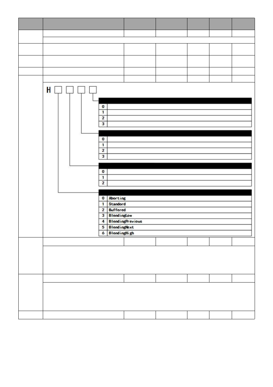
The 3rd bit

The 2nd bit

The 1st bit The 0 bit

Data group step change condition type 1

Pulse edge of signal input (/POS-SIEP)
Electrical level of signal input (/POS-SIEP)

The logical conditions between step change 1 and step change 2

Pulse edge of signal input (/POS-SIEP)
Electrical level of signal input (/POS-SIEP)

Connectionless
And (AND)
Or (OR)

Unconditional
Delay

Data group step change condition type 2

Unconditional
Delay

Step change transient mode

- 149 -

Reference

number

Name

Range

Unit

Factory

value

Effective

Remarks

Pn756

No. 7 data group type

---

--

0

Restart

0: the data group is invalid

1: the absolute motion mode

2: the relative motion mode

Pn757

No. 7 group data group low position

-9999 - +9 999

The

instruction unit

0

Restart

Pn758

No. 7 group data group high position

-9999 - +9 999

10000 the

instruction unit

0

Restart

Pn759

No. 7 data group operating speed

0 - 6000

1rpm

100

Restart

Pn760

No. 7 data group step changing property

---

--

0000

Restart

Pn761

No. 7 data group step change 1 value

0 - 65535

--

0

Restart

-Unconditional: no transition condition value

- Delay: value 0...65535, the waiting time is 0...65535, and the unit time is ms

- Pulse edge: the value 0 identifies the rising edge

value 1 indicates the descent edge

value 2 indicates

the rising edge or the descending edge

Electrical level: value 3 indicates 1 electrical level

value 4 indicates 0 electrical level

Pn762

No. 7 data group step change 2 value

0 - 65535

--

0

Restart

-Unconditional: no transition condition value

- Delay: value 0...65535, the waiting time is 0...65535, and the unit time is ms

- Pulse edge: the value 0 identifies the rising edge

value 1 indicates the descent edge

value 2 indicates

the rising edge or the descending edge

Electrical level: value 3 indicates 1 electrical level

value 4 indicates 0 electrical level

Pn763

No. 7 data group subsequent data group

0 - 14

--

9

Restart

The 3rd bit

The 2nd bit

The 1st bit The 0 bit

Data group step change condition type 1

Pulse edge of signal input (/POS-SIEP)
Electrical level of signal input (/POS-SIEP)

The logical conditions between step change 1 and step change 2

Pulse edge of signal input (/POS-SIEP)
Electrical level of signal input (/POS-SIEP)

Connectionless
And (AND)
Or (OR)

Unconditional
Delay

Data group step change condition type 2

Unconditional
Delay

Step change transient mode

- 150 -

Reference

number

Name

Range

Unit

Factory

value

Effective

Remarks

Pn764

Data group mode

0 - 1

--

0

Restart

0: internal mode (Single data group mode)

1: task mode (data group sequence)

Pn765

Data group acceleration

1-60000

10rpm/s

10000

Restart

Pn766

Data group speed deceleration

1-60000

10rpm/s

10000

Restart

Pn767

Step signal filtering time

0-1000

0.1ms

1

Restart

Pn768

Data

group

position

electronic

gear

(numerator)

1-1073741823

--

1

Restart

Pn770

Data

group

position

electronic

gear

(denominator)

1-1073741823

--

1

Restart

Pn772

Back to zero mode selection switch

----

--

0000

Restart

Pn773

Switch speed for reference point

0 - 6000

1rpm

100

Restart

Pn774

Switch speed for leaving reference point

0 - 6000

1rpm

30

Restart

Pn775

Speed / position switch reference point position

low point

0 - 9999

The instruction

unit

0

Immediately

Pn776

Speed / position switch reference point position

high point

0 - 9999

10000 the

instruction unit

0

Immediately

The 3rd bit

The 2nd bit

The 1st bit

The 0 bit

Back to zero mode setting

DS402 METHOD 35 (set the current position at zero point)

DS402 METHOD 1 (searching NOT switch operation towards the negative direction, requiring C pulse)

DS402 METHOD 2 (searching POT switch operation towards the positive direction, requiring C pulse)

DS402 METHOD 3 (searching reference point switch operation towards the positive direction, requiring C pulse)

DS402 METHOD 4 (searching reference point switch operation towards the positive direction, requiring C pulse)

DS402 METHOD 5 (looking for a NOT switch operation towards the negative direction, requiring C pulse)

DS402 METHOD 6 (looking for a NOT switch operation towards the negative direction, requiring C pulse)

DS402 METHOD 7 (looking for a NOT switch operation towards the negative direction, not requiring C pulse)

Orientation direction selection

Motor CCW selects rotation start to be directed to CCW direction, and the motor CW is rotated to the CW direction at startup.

Oriented by CCW

Oriented by CW

Mode switching selection

After effectively switching the signal, the position instruction of the control operation is completed and the speed control is

switched.

After effectively switching the signal, no matter whether the position instruction is completed, should switch to speed

control immediately.

Power on start and back to zero enable switch

Power on not start automatically and back to zero

Power on automatic starting and back to zero after the first times

SON

- 151 -

Appendix B Alarm Display list

Alarm number

Alarm name

Can it be

cleared

Main alarm

number

Auxiliary alarm

number

01

0

Encoder PA, PB, PC disconnection

Ok

02

0

Encoder PU, PV, PW disconnection

Ok

03

0

Overload

Ok

04

0

A/D transformation channel abnormal

Ok

10

0

Over current

Ok

11

0

Over voltage

No

12

0

Under voltage

No

13

0

Parameter failure

Ok

14

0

command over speed

Ok

1

Exceeding the speed limit of ,motor speed

Ok

15

0

Deviation counter overflow

Ok

16

0

Position offset too large

Ok

17

0

Electronic gear error

Ok

18

0

Error of the 1st channel current detection

Ok

19

0

Error of the 2nd channel current detection

Ok

22

0

Motor model error

Ok

23

0

The mismatch between the servo drive and

the motor

Ok

25

0

Bus type encoder multi-loop information

error

Ok

26

0

"bus type encoder multi-loop information

overflow

Ok

27

0

"bus type encoder battery alarm 1”

Ok

28

0

"bus type encoder battery alarm 2”

Ok

30

0

Discharge resistance wire break alarm

Ok

31

0

Regenerative overload

No

33

0

Instantaneous power failure alarm

Ok

34

0

Abnormity of rotating transformer

Ok

40

0

Bus type encoder communication error

Ok

41

0

Bus type encoder over speed

Ok

42

0

Absolute state error of bus type encoder

Ok

43

0

Bus type encoder counting error

Ok

44

0

Control domain of bus type encoder error

Ok

45

0

Bus type encoder communication data

error

Ok

46

0

Bus type encoder state domain error

Ok

47

0

Bus type encoder SFOME error

Ok

48

0

Bus type encoder EEROM uninitialized

Ok

49

0

Bus type encoder EEROM data check

error

Ok

60

0

MODBUS communication timeout

Ok

61

0

CANopen main station heartbeat timeout

Ok

63

0

Metrolink-II communication fault

Ok

64

0

Metrolink-II synchronization error

Ok

65

0

CANopen synchronization timeout

Ok

70

0

Driver overheating alarm

Ok

Alarm number

Alarm name

Can it be

cleared

- 152 -

Main alarm

number

Auxiliary alarm

number

71

0

Metrolink-III communication ASIC fault 1

No

1

Metrolink-III communication ASIC failure 2

No

73

0

Metrolink-III communication cycle setting error

Ok

1

Metrolink-III communication data size setting

incorrect

Ok

2

Metrolink-III communication station address

setting error

No

74

0

Metrolink-III communication synchronization

error

Ok

1

Metrolink-III communication synchronization

failure

Ok

75

0

Metrolink-III communication failure (reception

error)

Ok

1

Metrolink-III

transmission

cycle

error

(synchronous interval error)

Ok

3

Metrolink-III communication synchronization

frame not received

Ok

76

0

Data setting alarm 1 (parameter number)

Ok

1

Data setting alarm 2 (beyond the range of

parameters)

Ok

3

Data set alarm 4 (data length)

Ok

77

0

Metrolink-III command alarm 1 (beyond the

command condition)

Ok

1

Metrolink-III command alarm 2 (unsupported

command)

Ok

3

Metrolink-III command alarm 4 (command

interference)

Ok

4

Metrolink-III command alarm 5 (non - available

sub command)

Ok

6

Metrolink-III command alarm 7 (layer error)

Ok

80

0

Incorrect ESM requirements for fault protection

Ok

1

Undefined ESM requires fault protection

Ok

2

Boot status requirement fault protection

Ok

3

PLL not complete fault protection

Ok

4

PDO watchdog fault protection

Ok

6

PLL fault protection

Ok

7

Synchronization signal fault protection

Ok

81

0

Synchronization period setting fault protection

Ok

1

Mailbox setting fault protection

Ok

4

PDO watchdog setting fault protection

Ok

5

DC setting fault protection

Ok

6

SM event mode setting fault protection

Ok

7

SM2/3 setting fault protection

Ok

85

0

TxPDO distribution fault protection

Ok

1

RxPDO distribution fault protection

Ok

2

Lost link fault protection

Ok

3

SII EEPROM fault protection

Ok

88

1

Control mode setting fault protection

Ok

00

0

Error free display

--

(Note) 1. Alarm displays in “

”may be "A" or "B"; A or b axis alarm respectively.

2. -

25,

26,

27,

41 are required by the auxiliary function model and FA010/Fb010 The internal alarm clearance of encoder

can be used to reset the alarm.


Content      ..     8      9      10