HSD3 Series AC Servo Drive. User's Manual (Version: 3.1.14) - page 8
 

  Index      Manuals     HSD3 Series AC Servo Drive. User's Manual (Version: 3.1.14)


Search            copyright infringement  


Content      ..     6      7      8      9     ..


HSD3 Series AC Servo Drive. User's Manual (Version: 3.1.14) - page 8


- 116 -

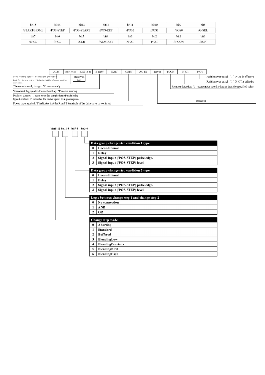
Input signal can input through the communication IO input (0451h) register the MODBUS communication, which is defined as follows:

The signal input in the register is valid only if the signal is not input from CN1 (the signal allocation parameter is set as "invalid").

Example: communication through the IO input /POS-START input register should set up P

512.1=0 modify input of IO (

0451

h

)

communication register and the bit13 bits will be valid.

*2. Servo operation state

0457

h

*3. Condition attributes of changing step

- 117 -

Chapter VII Maintenance and inspection

7.1 Exception diagnosis and treatment measures

7.1.1 Alarm display summary

The following table is shown the relationship between the alarm display and the alarm encoding output ON/OFF.

Motor stop method when alarm occurs: free running stop: the natural stopping method of friction resistance through the rotation of

the motor without braking.

Alarm number

Alarm name

Can it be

cleared

Main alarm

number

Auxiliary alarm

number

01

0

Encoder PA, PB, PC disconnection

Ok

02

0

Encoder PU, PV, PW disconnection

Ok

03

0

Overload

Ok

04

0

A/D transformation channel anomaly

Ok

10

0

Over current

Ok

11

0

Over voltage

No

12

0

Under voltage

No

13

0

Parameter failure

Ok

14

0

Instruction over speed

Ok

1

motor real speed is over than instruction

Ok

15

0

Deviation counter spillover

Ok

16

0

Position offset over than limit

Ok

17

0

Electronic gear error

Ok

18

0

The 1st channel exception of current detection

Ok

19

0

The 2nd channel exception of current detection

Ok

22

0

Motor model error

Ok

23

0

The mismatch between the servo drive and the

motor

Ok

25

0

Bus type encoder multi-loop information error

Ok

26

0

Bus type encoder multi-loop information overflow

Ok

27

0

Bus type encoder battery alarm 1

Ok

28

0

Bus type encoder battery alarm 2

Ok

30

0

Discharge resistance wire break alarm

Ok

31

0

Regenerative overload

No

34

0

Abnormity of rotating transformer

Ok

40

0

Bus type encoder communication exception

Ok

41

0

Bus type encoder over speed

Ok

42

0

Absolute state error of bus type encoder

Ok

43

0

Bus type encoder counting error

Ok

44

0

control domain verifying of bus type encoder error

Ok

45

0

Bus type encoder communication data verifying

error

Ok

46

0

Bus type encoder state domain error

Ok

47

0

Bus type encoder SFOME error

Ok

48

0

Bus type encoder EEROM uninitialized

Ok

49

0

Bus type encoder EEROM data check error

Ok

60

0

MODBUS communication timeout

Ok

61

0

CANopen main station heartbeat timeout

Ok

63

0

M-II communication fault

Ok

64

0

M-II synchronization exception

Ok

65

0

CANopen synchronization timeout

Ok

70

0

Driver overheating alarm

Ok

- 118 -

Alarm number

Alarm name

Can it be

cleared

Main alarm

number

Auxiliary alarm

number

71

0

M-III communication ASIC fault 1

No

1

M-III communication ASIC failure 2

No

73

0

M-III communication cycle setting error

Ok

1

M-III communication data size setting incorrect

Ok

2

M-III communication station address setting error

No

74

0

M-III communication synchronization exception

Ok

1

M-III communication synchronization failure

Ok

75

0

M-III communication failure (reception error)

Ok

1

M-III transmission cycle exception (synchronous

interval exception)

Ok

3

M-III communication synchronization frame

undeceived

Ok

76

0

Data setting alarm 1 (parameter number)

Ok

1

Data setting alarm 2 (beyond the range of

parameters)

Ok

3

Data set alarm 4 (data length)

Ok

77

0

M-III instruction alarm 1 (other than the instruction

condition)

Ok

1

M-III instruction alarm 2 (unsupported instruction)

Ok

3

M-III instruction alarm 4 (instruction interference)

Ok

4

M-III instruction alarm 5 (non - available sub

instruction)

Ok

6

M-III instruction alarm 7 (layer exception)

Ok

80

0

Incorrect ESM requirements for exception

protection

Ok

1

Undefined ESM requires exception protection

Ok

2

Boot status requirement exception protection

Ok

3

PLL not complete exception protection

Ok

4

PDO watchdog exception protection

Ok

6

PLL exception protection

Ok

7

Synchronization signal exception protection

Ok

81

0

Synchronization period setting exception

protection

Ok

1

Mailbox setting exception protection

Ok

4

PDO watchdog setting exception protection

Ok

5

DC setting exception protection

Ok

6

SM event mode setting exception protection

Ok

7

SM2/3 setting exception protection

Ok

85

0

TxPDO distribution exception protection

Ok

1

RxPDO distribution exception protection

Ok

2

Lost link exception protection

Ok

3

SII EEPROM exception protection

Ok

88

1

Control mode setting exception protection

Ok

00

0

Error free display

--

(Note):

1. “

” shown in alarm display may be "A" or "B”, alarm of A or b axis alarm respectively.

2.

25,

26,

27, and

41 it is necessary to clear the internal alarm through the auxiliary function mode, so that the alarm can

be reset.

- 119 -

7.1.2 The causes of alarm display and of alarm display

Whether servo drive adverse situation, the panel operator may appear with alarm display A□□ or b□□ the alarm displaying and its

handling measures are shown below.

Whether the adverse condition cannot be solved after the treatment, please contact the service department of our company.

1

Alarm display list

Call the

police

Alarm content

Alarm situation

Reason

Treatment measures

01

Incremental

encoder

ABC disconnection

Occur during the power supply is

connected or during operation

Encoder line welding error

Modify encoder wiring

The encoder cable has different specifications and disturbed

Change cable specification to multi -

stranded wire shield.

It is disturbed as the encoder cable is too long

The longest line distance of the wiring is

20m

The encoder cable is damaged.

Modify encoder cable casting

Encoder failure

Change of the servo motors

Servo drives circuit board failure.

Change the servo drive

03

Overload

Occurs when the control power

supply is connected

Servo drives circuit board failure.

Change the servo drive

Occurs when servo is ON

Motor wiring exception (adverse wiring and adverse connection)

Correct motor wiring

Encoder wiring exception (adverse wiring and adverse

connection)

Modify encoder wiring

Servo drives circuit board failure.

Change the servo drive

The servo motor is not rotated

when the instruction is input

Motor wiring exception (adverse wiring and adverse connection)

Correct motor wiring

Encoder wiring exception (adverse wiring and adverse

connection)

Modify encoder wiring

Starting torque exceeds the maximum torque

Reconsider the load conditions, operating

conditions, or reconsider the capacity of

the motor

It occurs under normal operation

The effective torque exceeds the rated torque or starting torque

to a large extent over the rated torque

Reconsider the load conditions, operating

conditions, or reconsider the capacity of

the motor

10

Over current

Occurs when the control power

supply is connected

Overloading alarm reset several times for power disconnection

Reset method for changing alarms

Servo drives circuit board failure.

Change the servo drive

It occurs over the main circuit

power or produce over current

during the operation of the motor

U, V, W and ground wire connection error

Check the wiring and connect it correctly

The short circuit between the U, V, W of the motor main electric

circuit and the ground wire

Amend or replace motor main circuit cable

The short circuit between the U, V, W of the motor main electric

circuit

Overloading alarm reset several times for power disconnection

Reset method for changing alarms

Sharp change in position speed instruction

Reassessment of instruction values

If the load is too large, and whether it is beyond the capacity of

regenerative processing.

Review the load conditions and operating

conditions

Encoder is slippery

Change of the servo motors

Servo unit fan stops rotating.

Change the servo drive

Servo drives circuit board failure.

11

Overpressure

Check it when the

main

circuit

power

supply is connected

Occurs when the control power

supply is connected

Servo drives circuit board failure.

Change the servo drive

When the main circuit power supply

is connected

It happens

AC power supply voltage is too high

Adjust the AC power supply voltage to the

normal range

Servo drives circuit board failure.

Change the servo drive

It occurs under normal operation

Check the AC power supply voltage (Whether there is too much

voltage change)

Adjust the AC power supply voltage to the

normal range

With high RPM, inertia of load too high(insufficient regeneration

capacity)

Review the load conditions and operating

conditions

Servo drives circuit board failure.

Change the servo drive

When the servo motor decelerates

With high RPM, inertia of load too high

Review the load conditions and operating

conditions

12

Under voltage

Check it when the

main

circuit

power

supply is connected

Occurs when the control power

supply is connected

Servo drives circuit board failure.

Change the servo drive

When the main circuit power supply

is connected

It happens

AC power supply voltage is too low

Adjust the AC power supply voltage to the

normal range

The fuse of the servo unit is blowed.

Change the servo drive

Impact current limit resistance disconnection (whether the power

supply voltage is exception, and whether impact current limit

resistance is overloaded)

Replace the servo unit (confirm the power

supply voltage, reduce the frequency of

the main circuit ON/OFF)

Servo drives circuit board failure.

Change the servo drive

It occurs under normal operation

AC power supply voltage is low (whether there is too large

pressure drop)

Adjust the AC power supply voltage to the

normal range

Instantaneous power failure

Restart operation by alarm reset

The short circuit of the motor main electric circuit

Amend or replace motor main circuit cable

13

Parameter failure

Occurs when the control power

supply is connected

Power off when the parameters is being setting

Perform

parameter

initialization

processing (F

011)

Servo drives circuit board failure.

Change the servo drive

14

Over speed

Occurs when the control power

supply is connected

Servo drives circuit board failure.

Change the servo drive

Occurs when servo is ON

Motor wiring U, V, W phase sequence error

Correct motor wiring

Encoder wiring error

Modify encoder wiring

Error action of encoder wiring due to interference

To

implement

the

anti-interference

countermeasures of encoder

Servo drives circuit board failure.

Change the servo drive

It occurs when the servo motor

starts running or rotating in a high

speed.

Motor wiring U, V, W phase sequence error

Correct motor wiring

Encoder wiring error

Modify encoder wiring

Error action of encoder wiring due to interference

To

implement

the

anti-interference

countermeasures of encoder

The input of position / speed instruction is too large

Down command value

Instruction input gain setting error

Correct command input gain

Servo drives circuit board failure.

Change the servo drive

15

Position counter

overflows

It occurs when the servo motor

starts running or rotating in a high

speed.

Motor locked-rotor

Check the load

Input instruction frequency exception

The

upper

computer

reduces

the

frequency

Wiring error

Correct wiring

16

Position offset too large

(The servo is in the ON

state

Lower position offset

over

User parameters

overflow

Occurs when the control power

supply is connected

The position offset large alarm electrical level (P

523) is not

correct.

Set the user parameter P

523 value

other than 0 value

Servo drives circuit board failure.

Change the servo drive

It takes place at high speed

The wiring of the U, V, W of the servo motor is exception

(incomplete connection)

Correct motor wiring
Modify encoder wiring

- 120 -

Call the

police

Alarm content

Alarm situation

Reason

Treatment measures

Electrical level P

523

setting)

Servo drives circuit board failure.

Change the servo drive

It occurs when the servo motor is

not rotated and the position

instruction is input

Adverse wiring of the U, V, W of the servo motor

Correct motor wiring

Servo drives circuit board failure.

Change the servo drive

The action is normal, but it occurs

for the long instruction.

The adverse gain adjustment of the servo drive

Increase the speed loop gain (P

100),

and the position loop gain (P

102)

The frequency of the position instruction pulse is too high

Slow down position instruction frequency

Add the smoothing function

Reevaluate the electronic gear ratio

The position offset large alarm electrical level (P

523) is not

correct.

Set the parameters of P

523

as the

correct value

Load conditions (torque, moment of inertia) are not consistent

with the motor specifications

Discuss reassessment of load or motor

capacity

17

Electronic gear error

Occurs when the control power

supply is connected

Electronic gear is not set correctly.

Reset P

202, P

204

It occurs when the servo motor

starts to run

18

The

1st

channel

exception

of

current

detection

Occurs when the control power

supply is connected

Servo drives circuit board failure.

Change the servo drive

It occurs when the servo motor

starts to run

19

The

1st

channel

exception

of

current

detection

Occurs when the control power

supply is connected

Servo drives circuit board failure.

Change the servo drive

It occurs when the servo motor

starts to run

22

Motor model error

Occurs when the control power

supply is connected

Drive motor parameters setting is exception

Change the servo drive

The parameter written to the encoder is exception

Change the servo motors( encoder)

Servo drives circuit board failure.

Change the servo drive

23

The mismatch between

the servo drive and the

motor

Occurs when the control power

supply is connected

The setting of drive motor model code is not set or set wrong

Set the correct motor model code

parameters

25

Multi loop data of bus

encoder error

Occurs when the control power

supply is connected

Absolute encoder multi loop data exception

The bus encoder is performed with

multiple loop positions (F

009) and clear

the bus encoder alarm registers (F

010)

It occurs when the servo motor is

running

26

The multi loop data of

the

bus

encoder

overflow

Occurs when the control power

supply is connected

Absolute encoder multi loop data exception

The bus encoder is performed with

multiple loop positions (F

009) and clear

the bus encoder alarm registers (F

010)

It occurs when the servo motor is

running

27

Bus encoder battery

alarm 1

Occurs when the control power

supply is connected

Battery is not correctly connected or not connected

Connect the battery correctly

Battery Voltage is low than the specific value (2.5V)

Replace the battery and restart the PG

power supply

28

Bus encoder battery

alarm 2

Occurs when the control power

supply is connected

Battery Voltage is low than the specific value (3.1V)

Replace the battery and restart the PG

power supply

30

Exception again

Occurs when the control power

supply is connected

Servo drives circuit board failure.

Change the servo drive

It occurs when the main circuit

power is connected

Not external connect the regenerated resistance

Connect the regenerated resistance

Check whether the regenerated resistance is defective, broken

or disconnected.

Correct the wiring of the external

regenerative resistance

It occurs under normal operation

Check whether the regenerative resistance is adverse connected

or whether it is fall off

Correct the wiring of the external

regenerative resistance

Regenerative resistance disconnected (whether the regenerative

energy is too large)

Replace the regenerative resistance or

replace the servo drive (reconsider the

load and operating conditions)

Fault of servo drive (regenerative transistor, voltage detection

part fault)

Change the servo drive

31

Regenerative overload

Occurs when the control power

supply is connected

Servo drives circuit board failure.

Change the servo drive

It occurs when the main circuit

power is connected

Power supply voltage is over 270V

Correcting voltage

It occurs under normal operation

(the

regenerated

resistance

temperature increases greatly)

Regenerative energy is too large

Choose the capacity of the regenerative

resistance again or reconsider the load

conditions and operating conditions

Under continuous regeneration state

When the servo motor decelerates

Regenerative energy is too large

Choose the capacity of the regenerative

resistance again or reconsider the load

conditions and operating conditions

40

Bus encoder counting

disconnection

Occurs when the control power

supply is connected

Encoder wiring error

Modify encoder wiring

Encoder failure

Change of the servo motors

Servo drives circuit board failure.

Change the servo drive

Occurs during the operation

Encoder wiring error

Modify encoder wiring

The encoder cable has different specifications and disturbed

Change cable specification to multi -

stranded wire shield.

It is disturbed as the encoder cable is too long

The longest line distance of the wiring is

20m

The encoder cable is damaged and the signal line is disturbed

Modify encoder cable casting

41

Bus encoder over speed

Occurs when the control power

supply is connected

Servo motor rotates at the speed over 100r/min when the PG

power is connected

Set PG power supply ON when the RPM

of servo motor is less than 100 r/min

Encoder failure

Change of the servo motors

Servo drives circuit board failure.

Change the servo drive

Occurs during the operation

Encoder failure

Change of the servo motors

Servo drives circuit board failure.

Change the servo drive

42

Bus encoder FS state

error

It occurs under normal operation

Encoder failure

Change of the servo motors

Servo drives circuit board failure.

Change the servo drive

- 121 -

Call the

police

Alarm content

Alarm situation

Reason

Treatment measures

43

Bus encoder counting

error

It occurs under normal operation

Servo drives circuit board failure.

Change the servo drive

44

Check

the

control

domain of bus encoder

error

Occur during the power supply is

connected or during operation

The encoder cable has different specifications and disturbed

Change cable specification to multi -

stranded wire shield.

It is disturbed as the encoder cable is too long

The longest line distance of the wiring is

20m

The encoder cable the damaged by engaging-in and foreskin,

and the signal line is disturbed.

Modify encoder cable casting

The encoder cable is tied up with large current line or too long

distance.

Lay the encoder cable in position where

the surge voltage is not applied.

The potential of FG is changed due to the influence of the motor

side equipment (welding machine, etc.).

Connect the equipment ground wire to

avoid FG shunting to the PG side

The signal line of the encoder is disturbed

To

implement

the

anti-interference

countermeasures of encoder

45

Check

the

control

domain of bus encoder

error

Occur during the power supply is

connected or during operation

Encoder wrong wiring and poor contact

Modify encoder wiring

The encoder cable has different specifications and disturbed

Change cable specification to multi -

stranded wire shield.

It is disturbed as the encoder cable is too long

The longest line distance of the wiring is

20m

The encoder cable the damaged by engaging-in and foreskin,

and the signal line is disturbed.

Modify encoder cable casting

The encoder cable is tied up with large current line or too long

distance.

Lay the encoder cable in position where

the surge voltage is not applied.

The potential of FG is changed due to the influence of the motor

side equipment (welding machine, etc.).

Connect the equipment ground wire to

avoid FG shunting to the PG side

The signal line of the encoder is disturbed

To

implement

the

anti-interference

countermeasures of encoder

Encoder failure

Change of the servo motors

Servo drives circuit board failure.

Change the servo drive

46

Bus

encoder

state

domain cutoff position

error

Occur during the power supply is

connected or during operation

Encoder wrong wiring and poor contact

Modify encoder wiring

The encoder cable has different specifications and disturbed

Change cable specification to multi -

stranded wire shield.

It is disturbed as the encoder cable is too long

The longest line distance of the wiring is

20m

The encoder cable the damaged by engaging-in and foreskin,

and the signal line is disturbed.

Modify encoder cable casting

The encoder cable is tied up with large current line or too long

distance.

Lay the encoder cable in position where

the surge voltage is not applied.

The potential of FG is changed due to the influence of the motor

side equipment (welding machine, etc.).

Connect the equipment ground wire to

avoid FG shunting to the PG side

The signal line of the encoder is disturbed

To

implement

the

anti-interference

countermeasures of encoder

Encoder failure

Change of the servo motors

Servo drives circuit board failure.

Change the servo drive

47

Bus encoder SFOME

cutoff position error

Occur during the power supply is

connected or during operation

Encoder wrong wiring and poor contact

Modify encoder wiring

The encoder cable has different specifications and disturbed

Change cable specification to multi -

stranded wire shield.

It is disturbed as the encoder cable is too long

The longest line distance of the wiring is

20m

The encoder cable the damaged by engaging-in and foreskin,

and the signal line is disturbed.

Modify encoder cable casting

The encoder cable is tied up with large current line or too long

distance.

Lay the encoder cable in position where

the surge voltage is not applied.

The potential of FG is changed due to the influence of the motor

side equipment (welding machine, etc.).

Connect the equipment ground wire to

avoid FG shunting to the PG side

The signal line of the encoder is disturbed

To

implement

the

anti-interference

countermeasures of encoder

Encoder failure

Change of the servo motors

Servo drives circuit board failure.

Change the servo drive

48

The bus encoder data is

not initialized

Occurs when the control power

supply is connected

Encoder EEROM uninitialized

Change of the servo motors

49

Bus encoder data and

counting check error

Occur during the power supply is

connected or during operation

Encoder wrong wiring and poor contact

Modify encoder wiring

The encoder cable has different specifications and disturbed

Change cable specification to multi -

stranded wire shield.

It is disturbed as the encoder cable is too long

The longest line distance of the wiring is

20m

The encoder cable the damaged by engaging-in and foreskin,

and the signal line is disturbed.

Modify encoder cable casting

The encoder cable is tied up with large current line or too long

distance.

Lay the encoder cable in position where

the surge voltage is not applied.

The potential of FG is changed due to the influence of the motor

side equipment (welding machine, etc.).

Connect the equipment ground wire to

avoid FG shunting to the PG side

The signal line of the encoder is disturbed

To

implement

the

anti-interference

countermeasures of encoder

Encoder failure

Change of the servo motors

Servo drives circuit board failure.

Change the servo drive

60

MODBUS

communication timeout

Occur during the power supply is

connected or during operation

MODBUS main station communication timeout

Check the MODBUS main station

61

CANopen main station

heartbeat timeout

Occur during the power supply is

connected or during operation

Heartbeat of the main station timeout

Inspect CANopen main station

70

Overheating

Occurs when the control power

supply is connected

Servo drives circuit board failure.

Change the servo drive

Overloading alarm reset several times for power disconnection

Reset method for changing alarms

The heat sink overheating occurs

while the main power supply is ON

or the motor runs

The load exceeds the rated load

Reconsider the load conditions, operating

conditions, or reconsider the capacity of

the motor

The ambient temperature of servo drive is over 55

Lower the ambient temperature of the

servo drive to 55

and below

Servo drives circuit board failure.

Change the servo drive

- 122 -

7.1.3 The causes and treatment measures of other reverse conditions

In the absence of alarm state, the reasons for the reverse situation and the appropriate measures to deal with it are as the following

table.

Whether the adverse condition cannot be solved after the treatment, please contact the company's agent or technical service

personnel.

Reverse condition

Reason

Inspection method

Treatment measures

: Please check and process the power of the servo system after put it at OFF.

Servo motor does not

start

Control power supply is not connected

Check the voltage between the control power

terminals.

Correct the control power supply ON circuit

Main circuit power supply is not connected

Check the voltage between the main circuit power

supply terminals.

Correct the main circuit power supply ON circuit

Input and output (CN1 connector) wiring error and fall off

Check the installation and wiring of CN1 connector

Wiring the CN1 connector correctly

Wiring of servo motor ad encoder comes off

Check the wiring

Connect the wiring

Form overload

Implement unloaded test operation

Reduce load, or replace the servo motor with large

capacity.

Not input the speed/position instruction

Check input pin

Correct input speed/position instruction

Set the input signal selection P

509

P

512 error

Check the setting of input signal P

509

P

512

Select the setting of input signal of P

509

P

512

correctly

Servo ON (/S-ON) input keeps in the OFF state

Confirm the setting value of user parameter

P

50A.0

Set the user setting correctly and set the ON server

(/S-ON) input at ON

SEN input keeps in the OFF state

Check SEN signal input (valid when using absolute

encoder)

Set the SEN signal input at ON

Mode selection of instruction pulse error

Check user parameters setting and instruction pulse

form

Set the user parameter setting of P

200.1 correctly

Speed control: speed instruction input is not appropriate

Confirm whether the control mode is consistent with

the input or check whether V-REF is consistent with

GND

Control parameter setting or input correctly

Torque control: torque instruction input is not appropriate

Confirm whether the control mode is consistent with

the input or check whether T-REF is consistent with

GND

Control parameter setting or input correctly

Position control: position instruction is not appropriate

Check P

200.1 command pulse form or symbol +

pulse signal

Control parameter setting or input correctly

Offset pulse clearance input (CLR) and keep it at the ON

state

Check /CLR input

Set /CLR input signal as OFF

Prohibit the forward drive (P-OT), and the reverse drive

(N-OT) input signal and keep it at the OFF state

Check POT or NOT input signal

Set POT or NOT input signal to ON

Servo drive failure

Servo drives circuit board failure.

Change the servo drive

The servo motor will

stop after an instant

operation.

Motor wiring error

Check the motor wiring

Electrical wiring correctly

Encoder wiring error

Check encoder wiring

Encoder wiring correctly

It stops all of sudden

during operation and

then motionless.

Alarm reset (ALM-RST) signal and keep it at the ON

state and active the alarm

Check alarm reset signal

The alarm reset signal is changed from ON to OFF

after the alarm is excluded

Motor rotation instability

Poor connection of the servo motor

Power line (U, V, W phase) and encoder connectors

are unstable.

Tighten the fastening part of the terminal and

connector.

The motor rotates

without instruction

Speed control: speed instruction input is not appropriate

Confirm whether the control mode is consistent with

the input or check whether V-REF is consistent with

GND

Control parameter setting or input correctly

Torque control: torque instruction input is not appropriate

Confirm whether the control mode is consistent with

the input or check whether T-REF is consistent with

GND

Control parameter setting or input correctly

Speed instructions is offset

The offset adjustment of the servo driver is poor

The offset adjustment of the servo driver

Position control: position instruction is not appropriate

Check P

200.1 command pulse form or symbol +

pulse signal

Control parameter setting or input correctly

Servo drive failure

Servo drives circuit board failure.

Change the servo drive

An abnormal sound

made from the motor

·Machine is not mounted properly

Is the servo motor mounting screw loose?

Tighten the mounting screws again

Is the core of the coupling aligned?

Aligning the axis core of the coupling.

Does the coupling lose balance?

Keep balance of the coupling

Exception in bearing

Check the sound and vibration conditions near the

bearing

If there are any exceptions, please contact our

technical service staff

The supporting machine has the vibration source

Is there any foreign matter entering or breaking or

deforming into the movable part of the mechanical

side?

Please consult the machine manufacturer

The input signal line specifications are different and are

disturbed

Multi - stranded wire or multi - stranded shielded

wire core 0.12mm2 above, multi - ply tinned copper

stranded wire?

The input signal line shall be conforming to the

specification

The length of the input signal line is disturbed due to

beyond the range of use

It is confirmed that the maximum line length is 3M,

and the impedance is less than 100 Omega.

Length of signal input line is conforms to the

specification

The encoder cable has different specifications and

disturbed

Multi - stranded wire or multi - stranded shielded

wire core 0.12mm2 above, multi - ply tinned copper

stranded wire?

Make the encoder cable conform to the specification

The length of the encoder cable is disturbed due to it

beyond the range of use

The longest line distance of the wiring is 20m

Make the length of encoder cable conform to the

specification

It is disturbed as the encoder cable is too long

The encoder cable the damaged by engaging-in

and foreskin, and the signal line is disturbed.

Modify encoder cable casting

Encoder cable excessive interference

Whether the encoder cable too closes?

Lay the encoder cable in position where the surge

voltage is not applied.

The potential of FG is changed due to the influence of

the motor side equipment (welding machine, etc.).

What is the grounding state of the servo motor side;

the welding machine and so on (forget ground, not

fully grounded)?

Connect the equipment ground wire to avoid FG

shunting to the PG side

The pulse count of the servo drive caused by the

interference error

Whether the signal line of the encoder is disturbed?

To implement the anti-interference countermeasures of

encoder

The encoder is affected by excessive vibration impact)

Mechanical vibration or the motor is not installed

properly

(Precision, fixing, partial core of installation surface

Decrease mechanical vibration or install servo motor

correctly

Encoder failure

Encoder failure

Change of the servo motors

The frequency is about

200 ~ 400Hz motor

vibration

The setting of speed gain of P

100 is too high

The factory setting

Kv=40.0Hz

Correctly set the speed loop gain P

100

The setting of position loop gain Pn102 is too high

The factory setting

Kp=40.0/s

Correctly set the position loop gain P

102

The setting of speed loop integral time parameter

P

101 is not appropriate

The factory setting : Ti=20.00ms

Set speed loop integral time parameter P

101

correctly

Automatic tuning: mechanical rigidity setting is not

properly

Re-evaluate the selection of mechanical rigidity

setting.

Select mechanical rigidity correctly

When the automatic tuning is not used: the moment of

inertia is not appropriate to the data

Check the inertia ratio data of P

103

Correct the inertia ratio data of P

103

The speed of starting

and stopping is too high.

The setting of speed gain of P

100 is too high

The factory setting

Kv=40.0Hz

Correctly set the speed loop gain P

100

The setting of position loop gain Pn102 is too high

The factory setting

Kp=40.0/s

Correctly set the position loop gain P

102

- 123 -

Reverse condition

Reason

Inspection method

Treatment measures

: Please check and process the power of the servo system after put it at OFF.

The setting of speed loop integral time parameter

P

101 is not appropriate

The factory setting : Ti=20.00ms

Set speed loop integral time parameter P

101

correctly

Automatic tuning: mechanical rigidity setting is not

properly

Re-evaluate the selection of mechanical rigidity

setting.

Select mechanical rigidity correctly

When the automatic tuning is not used: the moment of

inertia is not appropriate to the data

Check the inertia ratio data of P□103

Correct the inertia ratio data of P

103

Check the mode switch function

Absolute

encoder

position offset error

(The position of the

power

disconnected

from

the

instruction

controller is different

from the position of the

next power ON).

The encoder cable has different specifications and

disturbed

Multi - stranded wire or multi - stranded shielded

wire core 0.12mm2 above, multi - ply tinned copper

stranded wire?

Make the encoder cable conform to the specification

The length of the encoder cable is disturbed due to it

beyond the range of use

The longest line distance of the wiring is 20m

Make the length of encoder cable conform to the

specification

It is disturbed as the encoder cable is too long

The encoder cable the damaged by engaging-in

and foreskin, and the signal line is disturbed.

Modify encoder cable casting

Encoder cable excessive interference

Whether the encoder cable is tied up with large

current line or too close?

Lay the encoder cable in position where the surge

voltage is not applied.

The potential of FG is changed due to the influence of

the motor side equipment

What is the grounding state of the servo motor side;

the welding machine and so on (forget ground, not

fully grounded)?

Connect the equipment ground wire to avoid FG

shunting to the PG side

The pulse count of the servo drive caused by the

interference error

Whether the signal line of the encoder is disturbed?

To implement the anti-interference countermeasures of

encoder

The encoder is affected by excessive vibration impact

Mechanical vibration or the motor is not installed

properly

(Precision, fixing, partial core of installation surface)

Decrease mechanical vibration or install motor

correctly

Encoder failure

Encoder failure (impulse does not change)

Change of the servo motors

Servo drive failure

The servo driver does not send multiple rotation

data

Change the servo drive

The multi rotation data of instruction controller read error

Check the error detection of the check instruction

controller

Make the error detection part of the instruction

controller back to normal

Whether data is implemented in an instruction

controller (odd-even check)

Inspecting?

Odd-even check for multi rotation data

The signal line between the servo drive and the

command controller is disturbed

There will be interference (above) when there is no

checking.

Over travel (OT)

(It beyond the area

specified

by

the

command controller)

Prohibit forward / reverse drive input signal reaches

(POT or NOT H electrical level)

Is the voltage of the input signal using external

power (+24V) correct?

Correct external +24V power supply

Is the action state of the over travel limit SW

correct?

Correct the state of the over travel SW

Is the wiring of the over travel limit SW correct?

Amend the wiring of the modified over travel SW

Prohibit forward / reverse drive input signal generates

misoperation (POT or NOT signals are often changes)

The input signal with the external power supply

(+24V) and voltage will be changed?

Clear away the change of external +24V power supply

Whether the action state of the over travel limit SW

stable?

Make the action of the over travel limit SW stable

Is the wiring of the over travel limit SW correct?

(Cable damage, screw fastening)

Amend the wiring of the modified over travel SW

It is prohibited to have forward rotation/ reverse drive

input signal

(P-OT/N-OT) signal selection error

Check the POT signal selection P

510.2

Revise the POT signal selection P

510.2

Check the POT signal selection P

510.3

Revise the POT signal selection P

510.3

Motor stop method selection error

How to choose the inert operation stop at servo in

OFF state?

Check P

000.2, P

000.3

How about the inert operation setting for torque

control?

Check P

000.2, P

000.3

Over travel position inappropriately

The position of OT is shorter than the inert operation

Place the OT position in an appropriate state

The encoder cable has different specifications and

disturbed

Multi - stranded wire or multi - stranded shielded

wire core 0.12mm2 above, multi - ply tinned copper

stranded wire?

Make the encoder cable conform to the specification

The length of the encoder cable is disturbed due to it

beyond the range of use

The longest line distance of the wiring is 20m

Make the length of encoder cable conform to the

specification

It is disturbed as the encoder cable is too long

The encoder cable the damaged by engaging-in

and foreskin, and the signal line is disturbed.

Modify encoder cable casting

Encoder cable excessive interference

Whether the encoder cable is tied up with large

current line or too close?

Lay the encoder cable in position where the surge

voltage is not applied.

The potential of FG is changed due to the influence of

the motor side equipment (welding machine, etc.).

What is the grounding state of the servo motor side;

the welding machine and so on (forget ground, not

fully grounded)?

Connect the equipment ground wire to avoid FG

shunting to the PG side

Error of servo unit pulse counting caused by interference

Whether the signal line of the encoder is disturbed?

To implement the anti-interference countermeasures of

encoder

The encoder is affected by excessive vibration impact

Mechanical vibration or the servo motor is not

installed properly (mounting surface precision, fixed

and partial core)

Decrease mechanical vibration or install servo motor

correctly

Encoder failure

Encoder failure (impulse does not change)

Change of the servo motors

Servo drive failure

The servo driver does not send multiple rotation

data

Change the servo drive

Position

offset

(not

outputting

alarm,

causing position offset)

The coupling of mechanical and servo motor is

exception.

Whether the coupling part of the mechanical and

servo motor offset?

Connect the coupling between the machine and the

servo motor correctly

The input signal line specifications are different and are

disturbed

Multi - stranded wire or multi - stranded shielded

wire core 0.12mm2 above, multi - ply tinned copper

stranded wire?

The input signal line shall be conforming to the

specification

The length of the input signal line is disturbed due to

beyond the range of use

It is confirmed that the maximum line length is 3M,

and the impedance is less than 100

Ω

mega.

Length of signal input line is conforms to the

specification

Encoder failure (impulse does not change)

Encoder failure (impulse does not change)

Change of the servo motors

- 124 -

7.2 Maintenance and inspection of servo driver

7.21 Servo motor inspection

It is only necessary to perform daily simple inspection since AC servo motor does not have electrical brush. It is the general

standard in the table during inspection period. Please determine the most appropriate period of inspection according to the service

condition and operating environment.

Inspect items

Checking period

Essential for checking and

maintenance

Remarks

Confirmation of vibration

and sound

Every day

Judging it by feeling and

hearing.

No increase compared it to

usual.

Visual inspection.

As per the condition of

fouling

Clean it with cloth or air gun

Insulation resistance

measurement

At least once a year

Switch off the connection with

the servo unit and measure the

insulation resistance by 500V

tram egger. It is normal for the

resistance value exceeds 10M

EU.

Please contact the Vendor

when it is below 10M Europe.

Fluid seal replacement.

At least 1 times every

5000 hours

Please contact the Vendor.

Servo motors only has fluid

seal.

Comprehensive inspection

At least once in 20000

hours or every 5 years

Please contact the Vendor.

7.2.2 Inspection of servo drive

No need for daily inspection, but should check it more than once a year.

Inspect items

Checking period

Essential for checking and

maintenance

Remarks

Cleaning of the main body

and the circuit board

At least once a year

Please contact the Vendor.

Screw loosening

The wiring board, the connector

installation screw shall not be

loosened.

Please tighten it further.

7.2.3 General standards for replacement of internal components of servo drive

Mechanical wear and aging will occur in electrical and electronic parts. To ensure safety, please check regularly.

Please contact the Vendor for replacement of parts.

For the servo drive under overhaul of the company’s, its user parameters have been adjusted back to the factory setting. Please be

sure to reset the user parameters for using before running.

Part name

Standard replacing

years

Conditions of usage

Coolant fan

4 – 5 years

·

Ambient temperature annual

average 30

·

Load ratio: less than 80%

·

Operation rate: less than 20

hours / day

Smooth capacitor

7 – 8 years

Relay type

Fuse

10 years

Aluminum electrolytic

capacitor on printed circuit

board

5 years

- 125 -

Appendix A User parameters list

Parameter

number

Name

Range

Unit

Factory value

Effective

Remarks

Pn000

Basic switch of function selection 0

---

--

0010

Restart

Pn001

Basic switch 1of function selection

----

--

0001

Restart

Parameter

number

Name

Range

Unit

Factory value

Effective

Remarks

The 3rd bit

The 2nd bit

The 1st bit

The 0 bit

Direction of rotation selection

CCW (counter clockwise) for forward rotation direction
CW (clockwise) for forward rotation direction (reverse mode)

Control mode selection

Speed control (analog command)
Position control (pulse train command)
Torque control (analog command)
Internal set speed control (node instruction)
The internal setting speed control

(node instruction)

←→ speed control (analog command)

The internal setting speed control (

node instruction)

←→ speed control (pulse train command)

The internal setting speed control (

node instruction

)←→ torque control (analog command)

Position control (pulse train command )←→ speed control (analog command)
Position control (pulse train command )←→ torque control (analog command)
Torque Position control (analog command)←→ speed control (analog command)
Speed control (analog command )←→ Zero clamping position
Position control (pulse train command) ←→

position control (pulse prohibition)

Internal position control
Speed control (analog command: PCL control forward, NCL control reversal)
spindle Orientation control
Spindle speed / position (Cs) control

Servo OFF stopping

Reverse braking slows down and stops the motor and put it in free sliding state.
Put the motor in the state of inertia operating

The stopping mode of over

travel

OT

Reverse braking stops the motor deceleration and put it in free sliding state.
Reverse braking slows down and stops the motor and then put it in servo locking state
Put the motor in the state of inertia operating

The using method of encoder

Use as the absolute value encoder to enable the absolute data serial output (PG fractional frequency PA0 port)

Use as an incremental encoder.

The absolute encoder is used as the absolute encoder to disable the absolute data serial output

Speed control option (T-REF allocation)

None
Use T-REF as an external torque limit input.
Use T-REF as a torque feed forward input
Use T-REF as an external torque limit input when P-CL & N-CL are “valid”

Torque control option (V-REF allocation)

None
Use V-REF as an external torque limit input.

Feed forward selection under acceleration

Acceleration feed forward type 1 (filtering computational method)
Acceleration feed forward type 2 (fast computational method)

The 3rd bit

The 2nd bit

The 1st bit

The 0 bit

- 126 -

Parameter

number

Name

Range

Unit

Factory value

Effective

Remarks

Pn002

Basic switch 2 of function selection

----

--

0000

Restart

Pn003

Basic switch 3 of function selection

----

--

0000

Restart

Pn004

Basic switch 4 of function selection

----

--

1100

Restart

Pn100

Speed loop gain

1 - 20 000

0.1Hz

400

Immediately

Pn101

Speed loop integral time

1 - 40 000

0.01ms

2000

Immediately

Pn102

Position loop gain

1 - 20 000

0.1/s

400

Immediately

Pn103

Rotation inertia ratio

0 - 20 000

1%

0

Immediately

Pn104

2nd speed loop gain

1 - 20 000

0.1Hz

400

Immediately

Pn105

2nd speed loop integral time

1 - 40 000

0.01ms

2000

Immediately

Pn106

2nd position loop gain

1 - 20 000

0.1/s

400

Immediately

Pn107

Offset (speed offset)

1 - 2000

1rpm

0

Immediately

Parameter
number

Name

Range

Unit

Factory value

Effective

Remarks

Pn108

Offset superposition range

----

Command

pulse

0000

Immediately

The 3rd bit

The 2nd bit

The 1st bit

The 0 bit

The 3rd bit

The 2nd bit

The 1st bit

The 0 bit

The second electronic gear enables

Switch off the second electronic gear and /P-CON signal as P/P1 switch
Enable the 2nd electronic gear and /P-CON signal switching as the 2nd electronic gear only and it is valid when it is at

Pn000.1=1

Switching mode of electronic gear

Reserved by the manufacturer

Enabling energy filtering
Switch off enabling filtering

Serial encoder speed measurement filtering enable switch

Reserved by the manufacturer (do not change)

Constant for reservation (do not change)

Constant for reservation (do not change)

Constant for reservation (do not change)

Overload enhanced enable switch

Switch off overload enhancement

Enable overload enhancement function (enhanced overload capacity, suitable for frequent start and stop applications)

The 3rd bit

The 2nd bit

The 1st bit

The 0 bit

Close out-of-tolerance alarm detection
Enable the out-of-tolerance alarm (alarm when the deviation counter value is greater than Pn523)

Constant for reservation (do not change)

Constant for reservation (do not change)

Constant for reservation (do not change)

Out-of-tolerance alarm enable switch

- 127 -

Parameter
number

Name

Range

Unit

Factory value

Effective

Remarks

Pn109

Feed forward

0 - 100

1%

0

Immediately

Pn110

Feed forward filtering time

0 - 640

0.1ms

0

Immediately

Pn111

Acceleration feed forward percentage

0 - 100

1%

0

Immediately

Pn112

Acceleration feed forward filtering time

0 - 640

0.1ms

0

Immediately

Pn113

Gain type application switch

0000 - 0064

--

0004

Restart

Pn114

Mode switch (torque command)

0 - 300

1%

0

Immediately

Pn115

Mode switch (speed command)

0 – 100 00

1rpm

0

Immediately

Pn116

Mode switch (acceleration command)

0 - 300

10rpm/s

0

Immediately

Pn117

Mode switch (offset pulse)

0 – 100 00

Command

pulse

0

Immediately

Pn118

Gain switching delay time

0 – 200 00

0.1ms

0

Immediately

Pn119

Gain switching amplitude

0 – 200 00

--

0

Immediately

Pn113.1=2, Unit: 1%
Pn113.1=3, Unit: 1 command pulse

Pn113.1=4, Unit: 10rpm/s
Pn113.1=5, Unit: 1rpm

Pn113.1=6, Unit: 1 command pulse

Pn120

Position gain switching time

0 – 200 00

0.1ms

0

Immediately

Pn121

Position gain switching hysteresis loop

0 – 200 00

0.1ms

0

Immediately

Pn122

Friction load

1 - 3000

1 ‰

0

Immediately

Pn123

Friction compensation velocity hysteresis

loop

0 - 100

1rpm

0

Restart

Pn124

Viscous friction load

0 – 200 00

0.1Hz

0

Immediately

Pn125

Friction gain

0 – 200 00

1 ‰ /k rpm

0

Immediately

Pn126

Velocity observer period

0 – 300 00

0.1Hz

0

Immediately

The 3rd bit

The 2nd bit

The 1st bit

The 0 bit

Mode switch selection

Condition of internal torque command (Electrical level setting: P

114)

Condition of speed (Electrical level setting: P

115)

Condition of acceleration (Electrical level setting: P

116)

Condition of offset pulse command (Electrical level setting: P

117)

No mode switch function

Automatic gain switching condition selection

N

o automatic gain switching (fixed to the first group gain)

External switch gain switching (G-SEL signal)
Torque percentage switching
Only switch under the condition of position offset
Given acceleration value (10r/min/s)
Set speed value
Positional command input

Reserved by the manufacturer

Reserved by the manufacturer

- 128 -

Reference

number

Name

Range

Unit

Factory value

Effective

Remarks

Pn127

On-line automatic tuning type switch

-----

--

1340

Restart

Pn200

Selection switch of position control command form

----

--

0000

Restart

Real time automatic gain mechanical rigidity setting

The 3rd bit

The 2nd bit

The 1st bit

The 0 bit

Real time automatic gain setting

None real time automatic gain setting

Conventional mode (suitable for applications where load inertia remains unchanged in operating)

Conventional mode (suitable for applications where load inertia changes very little in operating)

Conventional mode (suitable for applications where load inertia changes very significantly in operating)

Vertical load (suitable for applications where load inertia remains unchanged in operating)

Vertical load (suitable for applications where load inertia changes very little in operating)

Vertical load (suitable for applications where load inertia changes very significantly in operating)

Power reset

Power reset

Power reset

Mechanical rigidity of real-time automatic gain adjustment may be chosen. The greater value set of the
parameter. Faster response. If the parameter is set up too big suddenly, the gain of the system will be
changed significantly, which result in great impact on the machine. And it is suggested that a smaller
value shall be set first, and increase the rigidity by monitoring the machine working status.

Reserved by the manufacturer

Conventional automatic adjustment mode setting

Rotation circle number: 1 circle, rotation direction: CCW → CW
Rotation circle number: 2 circle, rotation direction: CCW → CW
Rotation circle number: 3 circle, rotation direction: CCW → CW
Rotation circle number: 4 circle, rotation direction: CCW → CW
Rotation circle number: 1 circle, rotation direction: CW → CCW
Rotation circle number: 2 circle, rotation direction: CW → CCW
Rotation circle number: 3 circle, rotation direction: CW → CCW
Rotation circle number: 4 circle, rotation direction: CW

CCW

The 3rd bit

The 2nd bit

The 1st bit

The 0 bit

Offset pulse clearing mode

The offset pulse cleared under servo OFF condition, and the offset pulse is not cleared under the over travel status

The offset pulse is not cleared when the servo OFF or the over travel.

The offset pulse is cleared when the servo OFF or the over travel(except for zero clamp).

Command pulse form

Symbol + pulse
CW+CCW
PhaseA+PhaseB (1 time frequency)
PhaseA+PhaseB (double frequency)
PhaseA+PhaseB (quadrupling frequency)

The command pulse signal form negation

PULS command does not take the negation, and the SIGN command does not take negation
PULS command does not take the negation, and the SIGN command take negation
PULS command takes the negation, and the SIGN command does not take negation
PULS command takes the negation, and the SIGN command takes negation

Filter selection

Bus driver signal command input filter
Command input filter for collector open signal

- 129 -

Reference

number

Name

Range

Unit

Factory value

Effective

Remarks

Pn201

PG frequency number

16 – 32768

1P/rev

2500

Restart

Pn202

The 1st Electronic gear numerator

1 - 1073741823

--

1

Restart

Pn204

The 1st Electronic gear denominator

1 - 1073741823

--

1

Restart

Pn206

No. 2 Electronic gear numerator

1 - 1073741823

--

1

Restart

Pn208

Position command deceleration time

0 – 6400

0.1ms

0

Immediately

Pn209

Position command filtering form selection

0 – 1

--

0

Restart

Pn300

Speed command Input gain

0 - 3000

rpm/v

150

Immediately

Pn301

Internal speed 1

0 - 6000

rpm

100

Immediately

Pn302

Internal speed 2

0 - 6000

rpm

200

Immediately

Pn303

Internal speed 3

0 - 6000

rpm

300

Restart

Pn304

Jogging (JOG) speed

0 - 6000

rpm

500

Immediately

Pn305

Soft start acceleration time

0 - 10000

1ms

0

Immediately

Pn306

Soft start deceleration time

0 - 10000

1ms

0

Immediately

Pn307

Velocity command filtering constant

0 - 10000

1ms

0

Immediately

Pn308

S curve rising time

0 - 10000

1ms

0

Immediately

Pn309

Selection switch of position control

command format

----

--

0000

Restart

Pn400

Torque command input gain

10 - 100

0.1v/Nm

30

Immediately

Pn401

Torque command filtering time

0 - 250

0.1ms

4

Immediately

Pn402

2Nd torque command filtering time

0 - 250

0.1ms

4

Immediately

Pn403

Forward torque limit

0 - 300

1%

300

Immediately

Pn404

Reverse torque limit

0 - 300

1%

300

Immediately

Pn405

External limit of forward torque

0 - 300

1%

100

Immediately

Pn406

External limit of reverse torque

0 - 300

1%

100

Immediately

Pn407

External limit of inversed reverse braking

torque

0 - 300

1%

300

Immediately

Pn408

Speed limit under torque control

0 - 6000

1rpm

1500

Immediately

The 3rd bit

The 2nd bit

The 1st bit

The 0 bit

Soft start mode

Trapezoid
S curve
Acceleration and deceleration filtering

Add and less filtering form

The first filtering
The second filtering

Ratio selection of S curves

Close to the linear
Low
Medium
High

Reserved by the manufacturer

- 130 -

Reference

number

Name

Range

Unit

Factory value

Effective

Remarks

Pn409

1 segment frequency of notching filter

50 - 5000

1Hz

5000

Immediately

Pn410

1 segment depth of notching filter

0 - 100

--

10

Immediately

Pn411

2 segment frequency of notching filter

50 - 5000

1Hz

5000

Immediately

Pn412

2 segment depth of notching filter

0 - 100

--

10

Immediately

Pn413

B type vibration frequency

10 - 1000

0.1Hz

1000

Immediately

Pn414

B type vibration damping

0 - 200

--

25

Immediately

Pn500

Positioning completed width

0 - 1073741823

The instruction

unit

10

Immediately

Pn502

Rotating detectable value

0 - 3000

1rpm

20

Immediately

Pn503

Output range of speed uniform signal

0 - 100

1rpm

10

Immediately

Pn504

Zero clamping velocity value

0 - 3000

1rpm

10

Immediately

Pn505

Servo ON waiting time

0 - 2000

1ms

0

Immediately

Pn506

Brake command - servo OFF delay time

0 - 500

1ms

0

Immediately

Pn507

Brake command output speed value

0 - 6000

1rpm

100

Immediately

Pn508

Servo OFF- brake command waiting time

10 - 100

10ms

50

Immediately

Pn509

Input signal selection 0

----

--

4321

Restart

B axis: 8765

The 3rd bit

The 2nd bit

The 1st bit

The 0 bit

/S-ON signal allocation

Keep the signal as "invalid"
It is valid when CN1-IN1 input signal is ON
It is valid when CN1-IN2 input signal is ON
It is valid when CN1-IN3 input signal is ON
It is valid when CN1-IN4 input signal is ON
It is valid when CN1-IN5 input signal is ON
It is valid when CN1-IN6 input signal is ON
It is valid when CN1-IN7 input signal is ON
It is valid when CN1-IN8 input signal is ON
Keep the signal as "valid"

/P-CON signal allocation (P control when it is ON)

Same as /S-ON signal allocation

P-OT signal allocation (it is prohibited to have forward rotation side drive when it is OFF)

Keep the signal as "Prohibited to have forward rotation side drive"
It is valid when CN1-IN1 input signal is ON
It is valid when CN1-IN2 input signal is ON
It is valid when CN1-IN3 input signal is ON
It is valid when CN1-IN4 input signal is ON
It is valid when CN1-IN5 input signal is ON
It is valid when CN1-IN6 input signal is ON
It is valid when CN1-IN7 input signal is ON
It is valid when CN1-IN8 input signal is ON
Fix the signal as "Allowed to have forward rotation side drive"

N-OT signal allocation (it is prohibited to have reversal rotation side drive when it is OFF)

Same as P-OT signal allocation

- 131 -

Reference

number

Name

Range

Unit

Factory value

Effective

Remarks

Pn510

Input signal selection 1

----

--

8765

Restart

B axis: 0000

Pn511

Input signal selection 2

----

--

0000

Restart

Pn512

Input signal selection 3

----

--

0000

Restart

The 3rd bit

The 2nd bit

The 1st bit

The 0 bit

/ALIM-RST signal allocation (clear alarms when it is from OFF to ON)

Keep the signal at "OFF"
It is valid when CN1-IN1 input signal is ON
It is valid when CN1-IN2 input signal is ON
It is valid when CN1-IN3 input signal is ON
It is valid when CN1-IN4 input signal is ON
It is valid when CN1-IN5 input signal is ON
It is valid when CN1-IN6 input signal is ON
It is valid when CN1-IN7 input signal is ON
It is valid when CN1-IN8 input signal is ON
Keep the signal at “ON"

/CLR signal allocation

Same as /S-ON signal settings

/P-CL signal allocation

/N-CL signal allocation

Same as /S-ON signal settings

Same as /S-ON signal settings

The 3rd bit

The 2nd bit

The 1st bit

The 0 bit

/G-SEL signal allocation

Same as /S-ON signal settings

/POSO signal allocation [M2/M3: external interlock /EXT1 signal allocation] [ECAT: external/EXT1 signal allocation]

Same as /S-ON signal settings

Same as /S-ON signal settings

Same as /S-ON signal settings

/POS2 signal allocation [M2/M3: external interlock /EXT3 signal allocation]

/POS-START

/HOME-REF [M2/M3 bus: allocation of /DEC) signal of the original point reset reduction and deceleration switch

The 3rd bit

The 2nd bit

The 1st bit

The 0 bit

Same as /S-ON signal settings

Same as /S-ON signal settings

Same as /S-ON signal settings

Same as /S-ON signal settings

/POS-STEP

/POS-START-HOME

/POS1 signal allocation [M2/M3: external interlock /EXT1 signal allocation] [ECAT: external/EXT2 signal allocation]


Content      ..     6      7      8      9     ..