HSD3 Series AC Servo Drive. User's Manual (Version: 3.1.14) - page 7
 

  Index      Manuals     HSD3 Series AC Servo Drive. User's Manual (Version: 3.1.14)


Search            copyright infringement  


Content      ..     5      6      7      8     ..


HSD3 Series AC Servo Drive. User's Manual (Version: 3.1.14) - page 7


- 100 -

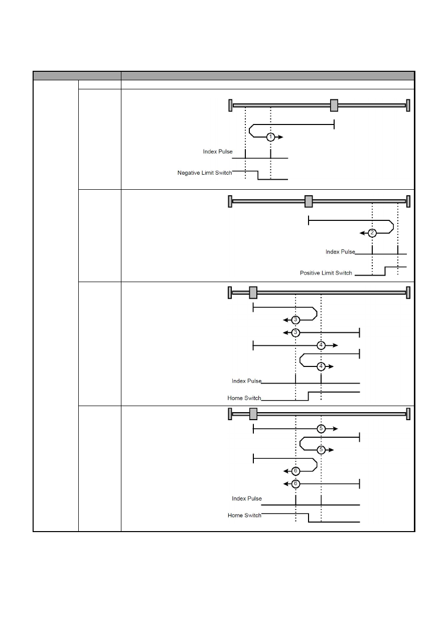
5.12.3 Locate the reference point (return to zero) operation

The zero point can also be determined by the datum point. The zero point is the reference point of the absolute motion in the mode

of motion sequence.

(1) User parameters setting

User parameters

Significance

P

772

H.

□□□

0

Current position is zero point

H.

□□□

1

H.

□□□

2

H.

□□□

3

H.

□□□

4

H.

□□□

5

H.

□□□

6

- 101 -

H.

□□□

7

H.

□□□

8

H.

□□□

9

H.

□□□

A

H.

□□□

B

H.

□□□

C

H.

□□□

D

H.

□□□

E

P

772

H.0

□□□

After power on, it does not return to zero automatically.

H.1

□□□

After power on, servo enable automatic return to zero in the 1st time, and the mode of return to

zero shall be determined by P

772.0.

(2) Input signal setting

Category

Signal name

Connector Pin number

Name

A axis

B-axis

Input

/POS-START

Need P

512 allocation

Mode motion sequence starting signal

Input

/HOME-REF

Need P

512 allocation

Zero point reference switch

Input

/POS-START-HOME Need P

512 allocation

Start return to zero, and locates the zero point according

to P

772.0.

When the /POS-START signal is ON, the motor operation is allowed (allowed return to zero); when it is OFF, the motor is

suspended (pause return to zero).

- 102 -

Chapter VI Communication

HSD3 standard servo drive is equipped with MODBUS communication with RS485 interface, and optional CANopen with CAN

interface (conforming to DS301 and DS402 standard protocol). The chapter mainly describes the MODBUS communication, and for

CANopen communication, please refers to the "HSD3 servo drive CANopen communication manual".

6.1 Communication connection

Signal name and function of communication connector are as follows:

Terminal number

1

2

3

4

5

6

7

8

Name

CN3

CANH-

CANL

GND

GND

RS485+ RS485- Reserve Reserve

CN4

CANH-

CANL

GND

GND

RS485+ RS485-

Built in 120 ohms

resistance

AC220V model definition

AC380 model definition

The servo drive CN3 is always adopted as the input terminal for the communication cable, and the CN4 is always adopted as the

output terminal of the communication cable. Multiple servo drive connection diagrams are as follows:

- 103 -

6.2 User parameters

User parameters

Significance

P

601

H.

□□□

0

RS485 communication baud rate

4800

bps

H.

□□□

1

RS485 communication baud rate

9600

bps

H.

□□□

2

RS485 communication baud rate

19200

bps

H.

□□□

3

RS485 communication baud rate

384600

bps

H.

□□

0

ASCII method

7 bits data bit

no verifying

2 bits stopping bit

H.

□□

1

ASCII method

7 bits data bit

even verifying

2 bits stopping bit

H.

□□

2

ASCII method

7 bits data bit

odd verifying

2 bits stopping bit

H.

□□

3

ASCII method

8 bits data bit

no verifying

1 bits stopping bit

H.

□□

4

ASCII method

8 bits data bit

even verifying

1 bit stopping bit

H.

□□

5

ASCII method

8 bits data bit

odd verifying

1 bit stopping bit

H.

□□

6

RTU method

8 bits data bit

no verifying

1 bit stopping bit

H.

□□

7

RTU method

8 bits data bit

even verifying

1 bit stopping bit

H.

□□

8

RTU method

8 bits data bit

odd verifying

1 bit stopping bit

- 104 -

6.3 MODBUS communication protocol

Using RS-485 communication, each servo drive must preset parameters P

600 ~ P

601. Communication mode adopts the

MODBUS protocol, which can be used in the following two modes:

ASCII mode

RTU mode.

The following is the description of MODBUS communication.

Encoding meaning

ASCII mode:

Each 8-bit data is composed of two ASCII characters. For example, a 1-byte data 64H (HEX). ASCII code “64” expression

contains ‘6’ ASCII code

36 H

and ‘4’ ASCII code

34 H

The number 0 to 9, the letter A to F ASCII code, as following table:

Character symbol

‘0’

‘1’

‘2’

‘3’

‘4’

‘5’

‘6’

‘7’

Corresponding ASCII code

30

H

31

H

32

H

33

H

34

H

35

H

36

H

37

H

Character symbol

‘8’

‘9’

‘A’

‘B’

‘C’

‘D’

‘E’

‘F’

Corresponding ASCII code

38

H

39

H

41

H

42

H

43

H

44

H

45

H

46

H

RTU mode:

Each 8-bit data is composed of two 4-bit's HEX data. For example, the decimal 100 is represented as 64 H with 1-byte RTU data.

Character structure

10bit character format (for 7-bit data)

- 105 -

11bit character format (for 8-bit data)

Communication data structure

Communication data structure:

ASCII mode:

STX

The starting character ':' = > (3A

H

)

ADR

Communication address

=>

1-byte including 2 ASCII codes

CMD

Command code

=>

1-byte contains 2 ASCII codes

DATA(n-1)

Data content

=>

n-word=2n-byte contains 4n ASCII codes

n is less than 12

……

DATA(0)

LRC

Check code

=>

1-byte contains 2 ASCII codes

End 1

End code 1 = > (0D

H

) (CR)

End 0

End code 0 = > (0A

H

) (LF)

RTU mode:

STX

At least 4 bytes transfer time at rest period.

ADR

Communication address = > 1-byte

CMD

Instruction code = > 1-byte

DATA(n-1)

Data content

=>

n-word=2n-byte

n not greater than 12

……

DATA(0)

CRC

CRC check code

=>

1-byte

End 1

At least 4 bytes transfer time at rest period.

- 106 -

The communication protocol data format is described as follows:

STX

(communication start)

ASCII mode

’ character.

RTU mode: more than 4 bytes communication time (automatically changed according to the speed of communication).

ADR

(communication address)

The legitimate address range is between 1 and 254.

For example, communicate with 32 servo address (Hex is 20):

ASCII mode

ADR=‘2’

‘0’=

‘2’=32

H

‘0’=30

H

RTU mode: ADR=20

H

CMD (command instruction) and DATA (data)

The format of the data is based on the command code. Commonly used command codes are as follows:

Command code: 03

H

, read N words (word), and the maximum N is 20.

For example, From the servo address as 01

H

reads two words from the starting address 0200

H.

ASCII mode:

Instruction information:

Response information:

RTU mode:

Instruction information:

Response information:

- 107 -

Instruction code: 06

H

, write 1 word (word)

For example, 100 (0064

H

) is written to the servo address 0200

H

of the address number 01

H

.

ASCII mode:

Instruction information:

Response information:

RTU mode:

Instruction information:

Response information:

- 108 -

The calculation of detection error value for LRC

ASCII mode

and CRC

RTU mode

The LRC calculation of the ASCII mode:

ASCII mode adopts the LRC (Longitudinal Redundancy Check) detection error value. LRC error detection value is the result

obtained by that the sum of the content from ADR to the final data, with 256 as unit, remove the exceeding part (e.g., the total result

is hexadecimal 128

H,

only take 28

H

) from the obtained result, and then, calculate its complement.

For example: read 1 word from the 0201 address of the office number 01

H

servo drive.

Add the data from ADR to the last data:

01

H

+03

H

+02

H

+01

H

+00

H

+01

H

=08

H

Complement of 2 for 08

H

is F8

H

, so LRC is' F ',' 8 '.

CRC calculation of the RTU mode

RTU mode adopts CRC (Cyclical Redundancy Check) detection error value.

Steps for calculating the CRC error value are as follows:

Step 1: load a 16-bit register with a content of FFFF H, which is called the "CRC" register.

Step two: XOR operation is conducted to the first bit (bit0) of instruction message and 16-bit CRC register of the least significant digit

(LSB), and furthermore, the result is saved to the CRC register;

Step three: check the lowest order (LSB) of the CRC register, if the bit is 0, the value of the CRC register makes 1 right shift, and if

the bit is 1, the CRC register makes 1 right shift and carries out XOR operation with A001

H

;

Step four: get back to step three till the step three has been executed for 8 times, and then, carry out step five;

Step five: for the next bit of the instruction message, repeat steps two to four till all bits have been processed like this, and at this

time, the content of CRC register is the CRC error detection value.

Specifications: after calculating the CRC error detection value, it needs to fill in the CRC low order in advance, and then, fill in the

CRC high order, please reference the following examples.

- 109 -

For example, 2 words (word) are read from the servo 0101

H

address of the office number of 01

H

. The final content of the CRC

register calculated from ADR to the number of data is 3794

H

, and the instruction message is shown below. Please be noted that 94

H is transmitted before 37h.

ADR

01

H

CMD

03

H

Start data address

01

H

(address high)

01

H

(address low)

Data number

(calculated by word)

00

H

(high)

02

H

(low)

CRC check low

94

H

(check low)

CRC check high

37

H

(check high)

End1, End0 (communication detection completed)

ASCII mode:

0D

H

character‘\r’

carriage return

and

0A

H

the character is ‘\n’

new line

』,

representing the end of the communication.

RTU mode:

The rest period of the 4 byte of communication time over the current communication rate indicates the end of the communication.

EXAMPLE:

The CRC value is generated from the C language below. The function requires two parameters:

Unsigned char * data;

Unsigned char length;

This function will pass back the CRC value of the unsigned integer type.

unsigned int crc_chk(unsigned char * data, unsigned char length){

int i,j;

unsigned int crc_reg = 0xFFFF;

while(length- -){

crc_ reg ^=*data++;

for(j=0;j<8;j++){

if(crc_reg & 0x01){

crc_reg=( crc_reg >>1)^0xA001;

}

Else

{

crc_reg

crc_reg >>1;

}

}

}

return crc_reg;

}

- 110 -

■ Communication error

During communication process, it is possible to go wrong, and the common error source is as follows:

Data address is wrong while reading and writing parameter;

The data exceeds the maximum value or is less than the minimum value of the parameter while writing parameter;

Communication is disturbed to cause data transmission error or check code error.

In case of occur the above two communication errors, the servo drive keeps normal operation and the servo drive makes a feedback

of error frame at the same time. In case of occurring the third kind of error, data transmission is regarded as invalidity discard and is

not back to the frame.

The wrong frame format is as follows:

Start

From the station address

Command

Data address, data, etc

Check

Command

Servo drive feedback error frame:

Start

From the station address

Responses codes

Error code

Check

Command + 80

H

Where

Error frame response code

command

80

H

Error code = 00

H

: normal communication;

= 01

H

: the servo drive cannot identify the requested function;

= 02

H

: the data address in the request does not exist in the servo drive;

= 03

H

: the data in the request is not allowed in the servo drive (exceeding the maximum or minimum of parameters);

= 04

H

: the servo drive has begun to implement the request, but cannot complete the request;

For example: servo drive axis No. 03

H

, the parameters of Pn100 write data 06

H

, because the parameter range of Pn100 is 0~6, so

write data will not be allowed, servo drive will return an error frame, error code 03H (greater than the parameters of the maximum or

minimum value), structure as follows:

Data frame of upper computer:

Start

From the station address

Command

Data address, data, etc

Check

03

H

06

H

0002

H

0006

H

Servo drive feedback error frame:

Start

From the station address

Responses codes

Error code

Check

03

H

86

H

03

H

In addition, if the passive station in the data frame transmitted by the upper computer is 00H, it shows that the data frame

is broadcast data and the servo drive does not return the frame.

- 111 -

6.4 MODBUS communication address

Communication data

address

Meaning

Description

Operation properties

Hexadecimal

Read and write

Length (bit)

0000

h

~ 03FF

h

Parameter area

Parameters in the corresponding parameter table

Readable and writable

16

0400

h

~0409

h

Alarm information in the storage area

10 historical alerts

Read-only

16

0420

h

Motor speed

Unit: 1r/min

Read only

32

0422

h

Angle of rotation (electric angle)

Unit: 1deg

Read-only

32

0424

h

Input instruction pulse speed

Unit: 1kHz

Read-only

32

0426

h

Busbar voltage

Unit: 1V

Read-only

32

0428

h

Analog input speed instruction value

Unit: 1 r/min

Read only

32

042A

h

The instruction percentage of analog input
torque

Unit: 1%

Read-only

32

042C

h

Percentage of internal torque instruction

Unit: 1% or 0.1A

Read only

32

042E

h

Input signals monitoring

——

Read only

32

0430

h

Output signals monitoring

——

Read only

32

0432

h

Encoder signal monitoring

——

Read only

32

0434

h

Input instruction pulse counter

Unit: 1 instruction pulse

Read-only

32

0436

h

Feedback pulse counter

Unit: 1 instruction pulse

Read-only

32

0438

h

Position offset counter

Unit: 1 instruction pulse

Read-only

32

043A

h

Cumulative load

Unit: 1%

Read-only

32

043C

h

Rotation inertia percentage

Unit: 1%

Read-only

32

043E

h

Actual angle of the encoder

Unit: 1 instruction pulse

Read-only

32

0440

h

Encoder multi loop position

Unit: 1 loop

Read-only

32

044A

h

Current alarm

Read-only

16

0451

h

Communication IO signal *1

It is not saved as power off

Readable and writable

16

0452

h

Communication output negation

It is not saved as power off

Readable and writable

16

0457

h

Servo operation state *2

Read only

16

045E

h

Software version number

Read only

16

045F

h

FPGA version number

Read only

16

0460

h

Electronic gear molecule

It is not saved as power off

Readable and writable

32

0462

h

Electronic gear denominator

It is not saved as power off

Readable and writable

32

0520

h

Clear the history alarm

1. Clear the history alarm

Readable and writable

16

0521

h

Clear the current alarm

1. Clear the current alarm

Readable and writable

16

0522

h

Clear bus encoder alarm

1. Clear bus encoder alarm

Readable and writable

16

0523

h

Clear the multi loop data of the bus encoder

1:Clear the multi loop data of the bus encoder

Readable and writable

16

0528

h

JOG speed (speed of P

304 setting)

BIT15:1 JOG servo enabling
BIT01:1 JOG+

JOG forward

BIT00:1 JOG+

JOG reversal

Readable and writable

16

0529

h

Position of JOG (speed of P

304 setting)

BIT15:1 Enter into the position point action mode.
BIT01:1 JOG-
BIT00:1 JOG+

Readable and writable

16

0540

h

Reset to Factory Defaults

1: Reset to Factory Defaults

Writable

16

0541

h

Reset

1

Reset

Writable

16

05F0

h

Currently running data numbers

Read-only

16

05F1

h

The running data group number

Read-only

16

05F2

h

16 bit low than practical position

Position contact electronic gear rear position

Read-only

16

05F3

h

The actual position is 16 bits high

Read-only

16

05F4

h

Position node mode

0: Task 1: external

Read-only

16

05F5

h

Acceleration

10rpm/s/s

Readable and writable

16

05F6

h

Deceleration

10rpm/s/s

Readable and writable

16

05F7

h

Emergency reduction

10rpm/s/s

Readable and writable

16

05F8

h

Position contact electron gear molecule

Readable and writable

16

05F9

h

Position contact electron gear denominator

Readable and writable

16

05FA

h

Locate the reference points

Readable and writable

16

05FB

h

Switch speed for reference point

0~6000 rpm

Readable and writable

16

05FC

h

Switch speed for leaving reference point

0~6000 rpm

Readable and writable

16

05FD

h

Low position of teaching position

Readable and writable

16

05FE

h

High position of teaching position

Readable and writable

16

Parameters of data group 0 :

0600

h

Low position of target position

Unit: 1 instruction pulse

Readable and writable

16

0601

h

High position of target position

Unit: 10000 instruction pulse

Readable and writable

16

0602

h

Target speed

rpm

Readable and writable

16

0603

h

Step change attributes *3

Readable and writable

16

0604

h

Value of the change step condition 1

Readable and writable

16

0605

h

2 numerical conditions of changing step

Readable and writable

16

0606

h

The following data group number

Readable and writable

16

0607

h

Data group type

0:NULL; 1: absolute; 2: relative

Readable and writable

16

Parameters of data group 1 :

- 112 -

Communication data

address

Meaning

Description

Operation properties

Hexadecimal

Read and write

Length (bit)

0608

h

Low position of target position

Unit: 1 instruction pulse

Readable and writable

16

0609

h

High position of target position

Unit: 10000 instruction pulse

Readable and writable

16

060A

h

Target speed

rpm

Readable and writable

16

060B

h

Condition attributes of changing step

Readable and writable

16

060C

h

Value of the change step condition 1

Readable and writable

16

060D

h

2 numerical conditions of changing step

Readable and writable

16

060E

h

The following data group number

Readable and writable

16

060F

h

Data group type

0:NULL; 1: absolute; 2: relative

Readable and writable

16

Parameters of data group 2 :

0610

h

Low position of target position

Unit: 1 instruction pulse

Readable and writable

16

0611

h

High position of target position

Unit: 10000 instruction pulse

Readable and writable

16

0612

h

Target speed

rpm

Readable and writable

16

0613

h

Condition attributes of changing step

Readable and writable

16

0614

h

Value of the change step condition 1

Readable and writable

16

0615

h

2 numerical conditions of changing step

Readable and writable

16

0616

h

The following data group number

Readable and writable

16

0617

h

Data group type

0:NULL; 1: absolute; 2: relative

Readable and writable

16

Parameters of data group 3 :

0618

h

Low position of target position

Unit: 1 instruction pulse

Readable and writable

16

0619

h

High position of target position

Unit: 10000 instruction pulse

Readable and writable

16

061A

h

Target speed

rpm

Readable and writable

16

061B

h

Condition attributes of changing step

Readable and writable

16

061C

h

Value of the change step condition 1

Readable and writable

16

061D

h

2 numerical conditions of changing step

Readable and writable

16

061E

h

The following data group number

Readable and writable

16

061F

h

Data group type

0:NULL; 1: absolute; 2: relative

Readable and writable

16

Parameters of data group 4 :

0620

h

Low position of target position

Unit: 1 instruction pulse

Readable and writable

16

0621

h

High position of target position

Unit: 10000 instruction pulse

Readable and writable

16

0622

h

Target speed

rpm

Readable and writable

16

0623

h

Condition attributes of changing step

Readable and writable

16

0624

h

Value of the change step condition 1

Readable and writable

16

0625

h

2 numerical conditions of changing step

Readable and writable

16

0626

h

The following data group number

Readable and writable

16

0627

h

Data group type

0:NULL; 1: absolute; 2: relative

Readable and writable

16

Parameters of data group 5 :

0628

h

Low position of target position

Unit: 1 instruction pulse

Readable and writable

16

0629

h

High position of target position

Unit: 10000 instruction pulse

Readable and writable

16

062A

h

Target speed

rpm

Readable and writable

16

062B

h

Condition attributes of changing step

Readable and writable

16

062C

h

Value of the change step condition 1

Readable and writable

16

062D

h

2 numerical conditions of changing step

Readable and writable

16

062E

h

The following data group number

Readable and writable

16

062F

h

Data group type

0:NULL; 1: absolute; 2: relative

Readable and writable

16

Parameters of data group 6 :

0630

h

Low position of target position

Unit: 1 instruction pulse

Readable and writable

16

0631

h

High position of target position

Unit: 10000 instruction pulse

Readable and writable

16

0632

h

Target speed

rpm

Readable and writable

16

0633

h

Condition attributes of changing step

Readable and writable

16

0634

h

Value of the change step condition 1

Readable and writable

16

0635

h

Value of the change step condition 2

Readable and writable

16

0636

h

The following data group number

Readable and writable

16

0637

h

Data group type

0:NULL; 1: absolute; 2: relative

Readable and writable

16

Parameters of data group 7 :

0638

h

Low position of target position

Unit: 1 instruction pulse

Readable and writable

16

0639

h

High position of target position

Unit: 10000 instruction pulse

Readable and writable

16

063A

h

Target speed

rpm

Readable and writable

16

063B

h

Condition attributes of changing step

Readable and writable

16

063C

h

Value of the change step condition 1

Readable and writable

16

063D

h

Value of the change step condition 2

Readable and writable

16

063E

h

Follow array number

Readable and writable

16

063F

h

Data group type

0:NULL; 1: absolute; 2: relative

Readable and writable

16

Parameters of data group 8 :

0640

h

Low position of target position

Unit: 1 instruction pulse

Readable and writable

16

0641

h

High position of target position

Unit: 10000 instruction pulse

Readable and writable

16

0642

h

Target speed

rpm

Readable and writable

16

0643

h

Condition attributes of changing step

Readable and writable

16

0644

h

Value of the change step condition 1

Readable and writable

16

0645

h

Value of the change step condition 2

Readable and writable

16

0646

h

The subsequent data group number

Readable and writable

16

0647

h

Data group type

0:NULL; 1: absolute; 2: relative

Readable and writable

16

- 113 -

Communication data

address

Meaning

Description

Operation properties

Hexadecimal

Read and write

Length (bit)

Parameters of data group 9 :

0648

h

Low position of target position

Unit: 1 instruction pulse

Readable and writable

16

0649

h

High position of target position

Unit: 10000 instruction pulse

Readable and writable

16

064A

h

Target speed

rpm

Readable and writable

16

064B

h

Condition attributes of changing step

Readable and writable

16

064C

h

Value of the change step condition 1

Readable and writable

16

064D

h

2 numerical conditions of changing step

Readable and writable

16

064E

h

The following data group number

Readable and writable

16

064F

h

Data group type

0:NULL; 1: absolute; 2: relative

Readable and writable

16

Parameters of data group 10 :

0650

h

Low position of target position

Unit: 1 instruction pulse

Readable and writable

16

0651

h

High position of target position

Unit: 10000 instruction pulse

Readable and writable

16

0652

h

Target speed

rpm

Readable and writable

16

0653

h

Condition attributes of changing step

Readable and writable

16

0654

h

Value of the change step condition 1

Readable and writable

16

0655

h

2 numerical conditions of changing step

Readable and writable

16

0656

h

The following data group number

Readable and writable

16

0657

h

Data group type

0:NULL; 1: absolute; 2: relative

Readable and writable

16

Parameters of data group 11 :

0658

h

Low position of target position

Unit: 1 instruction pulse

Readable and writable

16

0659

h

High position of target position

Unit: 10000 instruction pulse

Readable and writable

16

065A

h

Target speed

rpm

Readable and writable

16

065B

h

Condition attributes of changing step

Readable and writable

16

065C

h

Value of the change step condition 1

Readable and writable

16

065D

h

2 numerical conditions of changing step

Readable and writable

16

065E

h

The following data group number

Readable and writable

16

065F

h

Data group type

0:NULL; 1: absolute; 2: relative

Readable and writable

16

Parameters of data group 12 :

0660

h

Low position of target position

Unit: 1 instruction pulse

Readable and writable

16

0661

h

High position of target position

Unit: 10000 instruction pulse

Readable and writable

16

0662

h

Target speed

rpm

Readable and writable

16

0663

h

Condition attributes of changing step

Readable and writable

16

0664

h

Value of the change step condition 1

Readable and writable

16

0665

h

2 numerical conditions of changing step

Readable and writable

16

0666

h

The following data group number

Readable and writable

16

0667

h

Data group type

0:NULL; 1: absolute; 2: relative

Readable and writable

16

Parameters of data group 13 :

0668

h

Low position of target position

Unit: 1 instruction pulse

Readable and writable

16

0669

h

High position of target position

Unit: 10000 instruction pulse

Readable and writable

16

066A

h

Target speed

rpm

Readable and writable

16

066B

h

Condition attributes of changing step

Readable and writable

16

066C

h

Value of the change step condition 1

Readable and writable

16

066D

h

2 numerical conditions of changing step

Readable and writable

16

066E

h

The following data group number

Readable and writable

16

066F

h

Data group type

0:NULL; 1: absolute; 2: relative

Readable and writable

16

Parameters of data group 14 :

0670

h

Low position of target position

Unit: 1 instruction pulse

Readable and writable

16

0671

h

High position of target position

Unit: 10000 instruction pulse

Readable and writable

16

0672

h

Target speed

rpm

Readable and writable

16

0673

h

Condition attributes of changing step

Readable and writable

16

0674

h

Value of the change step condition 1

Readable and writable

16

0675

h

2 numerical conditions of changing step

Readable and writable

16

0676

h

The following data group number

Readable and writable

16

0677

h

Data group type

0:NULL; 1: absolute; 2: relative

Readable and writable

16

Parameters of data group 15 :

0678

h

Low position of target position

Unit: 1 instruction pulse

Readable and writable

16

0679

h

High position of target position

Unit: 10000 instruction pulse

Readable and writable

16

067A

h

Target speed

rpm

Readable and writable

16

067B

h

Condition attributes of changing step

Readable and writable

16

067C

h

Value of the change step condition 1

Readable and writable

16

067D

h

2 numerical conditions of changing step

Readable and writable

16

067E

h

The following data group number

Readable and writable

16

067F

h

Data group type

0:NULL; 1: absolute; 2: relative

Readable and writable

16

Parameters of data group 16 :

0680

h

Low position of target position

Unit: 1 instruction pulse

Readable and writable

16

0681

h

High position of target position

Unit: 10000 instruction pulse

Readable and writable

16

0682

h

Target speed

rpm

Readable and writable

16

0683

h

Condition attributes of changing step

Readable and writable

16

0684

h

Value of the change step condition 1

Readable and writable

16

0685

h

2 numerical conditions of changing step

Readable and writable

16

0686

h

The following data group number

Readable and writable

16

- 114 -

Communication data

address

Meaning

Description

Operation properties

Hexadecimal

Read and write

Length (bit)

0687

h

Data group type

0:NULL; 1: absolute; 2: relative

Readable and writable

16

Parameters of data group 17 :

0688

h

Low position of target position

Unit: 1 instruction pulse

Readable and writable

16

0689

h

High position of target position

Unit: 10000 instruction pulse

Readable and writable

16

068A

h

Target speed

rpm

Readable and writable

16

068B

h

Condition attributes of changing step

Readable and writable

16

068C

h

Value of the change step condition 1

Readable and writable

16

068D

h

Value of the change step condition 2

Readable and writable

16

068E

h

The following data group number

Readable and writable

16

068F

h

Data group type

0:NULL; 1: absolute; 2: relative

Readable and writable

16

Parameters of data group 18 :

0690

h

Low position of target position

Unit: 1 instruction pulse

Readable and writable

16

0691

h

High position of target position

Unit: 10000 instruction pulse

Readable and writable

16

0692

h

Target speed

rpm

Readable and writable

16

0693

h

Condition attributes of changing step

Readable and writable

16

0694

h

Value of the change step condition 1

Readable and writable

16

0695

h

2 numerical conditions of changing step

Readable and writable

16

0696

h

The following data group number

Readable and writable

16

0697

h

Data group type

0:NULL; 1: absolute; 2: relative

Readable and writable

16

Parameters of data group 19 :

0698

h

Low position of target position

Unit: 1 instruction pulse

Readable and writable

16

0699h

High position of target position

Unit: 10000 instruction pulse

Readable and writable

16

069A

h

Target speed

rpm

Readable and writable

16

069B

h

Condition attributes of changing step

Readable and writable

16

069C

h

Value of the change step condition 1

Readable and writable

16

069D

h

2 numerical conditions of changing step

Readable and writable

16

069E

h

The following data group number

Readable and writable

16

069F

h

Data group type

0:NULL; 1: absolute; 2: relative

Readable and writable

16

Parameters of data group 20 :

06A0

h

Low position of target position

Unit: 1 instruction pulse

Readable and writable

16

06A1

h

High position of target position

Unit: 10000 instruction pulse

Readable and writable

16

06A2

h

Target speed

rpm

Readable and writable

16

06A3

h

Condition attributes of changing step

Readable and writable

16

06A4

h

Value of the change step condition 1

Readable and writable

16

06A5

h

2 numerical conditions of changing step

Readable and writable

16

06A6

h

The following data group number

Readable and writable

16

06A7

h

Data group type

0:NULL; 1: absolute; 2: relative

Readable and writable

16

Data group 21 parameters:

06A8

h

Low position of target position

Unit: 1 instruction pulse

Readable and writable

16

06A9

h

High position of target position

Unit: 10000 instruction pulse

Readable and writable

16

06AA

h

Target speed

rpm

Readable and writable

16

06AB

h

Condition attributes of changing step

Readable and writable

16

06AC

h

Value of the change step condition 1

Readable and writable

16

06AD

h

2 numerical conditions of changing step

Readable and writable

16

06AE

h

The following data group number

Readable and writable

16

06AF

h

Data group type

0:NULL; 1: absolute; 2: relative

Readable and writable

16

Parameters of data group 22 :

06B0

h

Low position of target position

Unit: 1 instruction pulse

Readable and writable

16

06B1

h

High position of target position

Unit: 10000 instruction pulse

Readable and writable

16

06B2

h

Target speed

rpm

Readable and writable

16

06B3

h

Condition attributes of changing step

Readable and writable

16

06B4

h

Value of the change step condition 1

Readable and writable

16

06B5

h

2 numerical conditions of changing step

Readable and writable

16

06B6

h

The following data group number

Readable and writable

16

06B7

h

Data group type

0:NULL; 1: absolute; 2: relative

Readable and writable

16

Parameters of data group 23 :

06B8

h

Low position of target position

Unit: 1 instruction pulse

Readable and writable

16

06B9

h

High position of target position

Unit: 10000 instruction pulse

Readable and writable

16

06BA

h

Target speed

rpm

Readable and writable

16

06BB

h

Condition attributes of changing step

Readable and writable

16

06BC

h

Value of the change step condition 1

Readable and writable

16

06BD

h

2 numerical conditions of changing step

Readable and writable

16

06BE

h

The following data group number

Readable and writable

16

06BF

h

Data group type

0:NULL; 1: absolute; 2: relative

Readable and writable

16

Parameters of data group 24 :

06C0

h

Low position of target position

Unit: 1 instruction pulse

Readable and writable

16

06C1

h

High position of target position

Unit: 10000 instruction pulse

Readable and writable

16

06C2

h

Target speed

rpm

Readable and writable

16

06C3

h

Condition attributes of changing step

Readable and writable

16

06C4

h

Value of the change step condition 1

Readable and writable

16

06C5

h

2 numerical conditions of changing step

Readable and writable

16

- 115 -

Communication data

address

Meaning

Description

Operation properties

Hexadecimal

Read and write

Length (bit)

06C6

h

The following data group number

Readable and writable

16

06C7

h

Data group type

0:NULL; 1: absolute; 2: relative

Readable and writable

16

Parameters of data group 25 :

06C8

h

Low position of target position

Unit: 1 instruction pulse

Readable and writable

16

06C9

h

High position of target position

Unit: 10000 instruction pulse

Readable and writable

16

06CA

h

Target speed

rpm

Readable and writable

16

06CB

h

Condition attributes of changing step

Readable and writable

16

06CC

h

Value of the change step condition 1

Readable and writable

16

06CD

h

2 numerical conditions of changing step

Readable and writable

16

06CE

h

The following data group number

Readable and writable

16

06CF

h

Data group type

0:NULL; 1: absolute; 2: relative

Readable and writable

16

Parameters of data group 26 :

06D0

h

Low position of target position

Unit: 1 instruction pulse

Readable and writable

16

06D1

h

High position of target position

Unit: 10000 instruction pulse

Readable and writable

16

06D2

h

Target speed

rpm

Readable and writable

16

06D3

h

Condition attributes of changing step

Readable and writable

16

06D4

h

Value of the change step condition 1

Readable and writable

16

06D5

h

2 numerical conditions of changing step

Readable and writable

16

06D6

h

The following data group number

Readable and writable

16

06D7

h

Data group type

0:NULL; 1: absolute; 2: relative

Readable and writable

16

Parameters of data group 27 :

06D8

h

Low position of target position

Unit: 1 instruction pulse

Readable and writable

16

06D9

h

High position of target position

Unit: 10000 instruction pulse

Readable and writable

16

06DA

h

Target speed

rpm

Readable and writable

16

06DB

h

Condition attributes of changing step

Readable and writable

16

06DC

h

Value of the change step condition 1

Readable and writable

16

06DD

h

Value of the change step condition 2

Readable and writable

16

06DE

h

The following data group number

Readable and writable

16

06DF

h

Data group type

0:NULL; 1: absolute; 2: relative

Readable and writable

16

Parameters of data group 28 :

06E0

h

Low position of target position

Unit: 1 instruction pulse

Readable and writable

16

06E1

h

High position of target position

Unit: 10000 instruction pulse

Readable and writable

16

06E2

h

Target speed

rpm

Readable and writable

16

06E3

h

Condition attributes of changing step

Readable and writable

16

06E4

h

Value of the change step condition 1

Readable and writable

16

06E5

h

2 numerical conditions of changing step

Readable and writable

16

06E6

h

The following data group number

Readable and writable

16

06E7

h

Data group type

0:NULL; 1: absolute; 2: relative

Readable and writable

16

Parameters of data group 29 :

06E8

h

Low position of target position

Unit: 1 instruction pulse

Readable and writable

16

06E9

h

High position of target position

Unit: 10000 instruction pulse

Readable and writable

16

06EA

h

Target speed

rpm

Readable and writable

16

06EB

h

Condition attributes of changing step

Readable and writable

16

06EC

h

Value of the change step condition 1

Readable and writable

16

06ED

h

2 numerical conditions of changing step

Readable and writable

16

06EE

h

The following data group number

Readable and writable

16

06EF

h

Data group type

0:NULL; 1: absolute; 2: relative

Readable and writable

16

Parameters of data group 30 :

06F0

h

Low position of target position

Unit: 1 instruction pulse

Readable and writable

16

06F1

h

High position of target position

Unit: 10000 instruction pulse

Readable and writable

16

06F2

h

Target speed

rpm

Readable and writable

16

06F3

h

Condition attributes of changing step

Readable and writable

16

06F4

h

Value of the change step condition 1

Readable and writable

16

06F5

h

2 numerical conditions of changing step

Readable and writable

16

06F6

h

The following data group number

Readable and writable

16

06F7

h

Data group type

0:NULL; 1: absolute; 2: relative

Readable and writable

16

Parameters of data group 31 :

06F8

h

Low position of target position

Unit: 1 instruction pulse

Readable and writable

16

06F9

h

High position of target position

Unit: 10000 instruction pulse

Readable and writable

16

06FA

h

Target speed

rpm

Readable and writable

16

06FB

h

Condition attributes of changing step

Readable and writable

16

06FC

h

Value of the change step condition 1

Readable and writable

16

06FD

h

2 numerical conditions of changing step

Readable and writable

16

06FE

h

The following data group number

Readable and writable

16

06FF

h

Data group type

0:NULL; 1: absolute; 2: relative

Readable and writable

16

Address description:

*1. Communication IO input (0451

h

)


Content      ..     5      6      7      8     ..