HSD3 Series AC Servo Drive. User's Manual (Version: 3.1.14) - page 5
 

  Index      Manuals     HSD3 Series AC Servo Drive. User's Manual (Version: 3.1.14)


Search            copyright infringement  


Content      ..     3      4      5      6     ..


HSD3 Series AC Servo Drive. User's Manual (Version: 3.1.14) - page 5


- 68 -

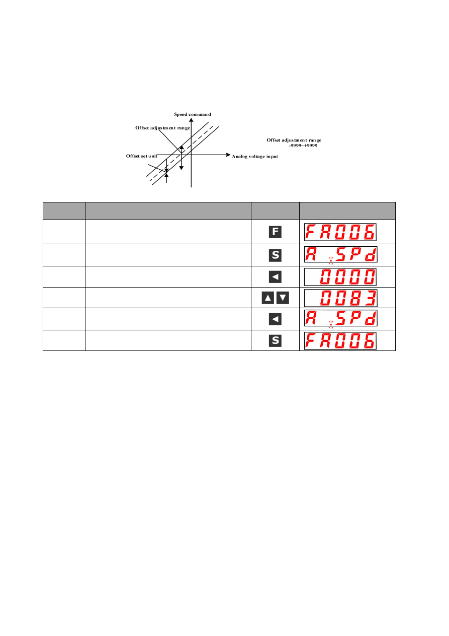
(2) Manual adjustment of speed instruction offset

Please use the manual adjustment (F

006) of the speed instruction offset in the following situations.

·

The instruction controller configures the position ring to set the offset pulse of the servo lock at zero.

·

Set the offset to a certain amount consciously

·

Confirm the offset data group with automatic adjustment

The basic function and the analog (speed and torque) automatically adjust instruction offset (F / 008) are the same, but when it is in

the manual adjustment (F - 006), it must be in direct input offset and adjustment.

The adjustment range of the offset and the setting unit are shown as follows.

Please adjust the A axis speed instruction offset manually according to the following steps.

Work

procedure

Work instruction

Action Keys

Post operation display

1

Please press down F function key and select A axis

auxiliary function mode. Press UP key or DOWN key

to set the FA006 whether FA006 is not displayed.

2

“A.SPd” is displayed by press down the settings key.

3

Please press the setting key 1s above and displays

"0000".

4

Press down UP key or DOWN key to set offset

quantity.

5

Please press the setting key 1s above and save the

offset data.

6

Return to the FA006 display by press down the

settings key.

- 69 -

5.5.4 Soft start

Soft start refers to the function of switching the step velocity instruction into the instruction of acceleration/deceleration certainly in

the internal servo drive.

(1) Trapezoid starting

User parameters

Significance

P

309

H.

□□□

0

Trapezoid starting

(2) S curve way starting

User parameters

Significance

P

309

H.

□□□

1

S curve way starting

H.

0

□□

Close to the linear

Ratio selection of S curves

H.

1

□□

Low

H.

2

□□

Medium

H.

3

□□

High

- 70 -

(3) Acceleration and deceleration filter mode starting

User parameters

Significance

P

309

H.

□□□

2

Acceleration and deceleration filter mode starting

H.

□□

0

The first times acceleration and deceleration filtering

H.

□□

1

The second times acceleration and deceleration filtering

5.5.5 The use of zero clamping function

(1) The meaning of zero clamping

It refers to the function used in the condition that instruction control unit is not configured with position loop system under speed

control mode.

If zero clamping (/P-CON) signal is set as ON, and when the input voltage of speed instruction (V-REF) is up to below the revolving

speed of P

501(zero clamping level), position loop is configured in the servo motor, the speed instruction is ignored, and

furthermore, make the servo motor stopping urgently to get into servo lockout state.

The servo motor is clamped into the ± 1 pulse in the valid position of zero clamping, although it is rotated via external force, it still can

return to the zero clamping position.

User parameters

Significance

P

000

H.

□□

A

Control mode



speed control (analog voltage instruction) zero clamping

Zero clamping action switching conditions

Set P

000= H.

□□

A

□,

and as long as one of the following two conditions is established, the zero clamping action will be

entered.

·

/P-CON is ON(L electrical level)

·

The speed instruction (V-REF) is lower than the set value of P

501

- 71 -

(3) Input signal setting

Category Signal name

Connector pin number

(leave factory)

Setting

Significance

A axis

B-axis

Input

/P-C0N

CN1-IN2

CN1-IN6

ON =L electrical level

Zero clamping function ON (valid)

OFF=H electrical level

Zero clamping function OFF (invalid)

It is input signal for switching to zero clamping action.

Any one of the /P-CON signals can be switched to zero clamping.

For distribution method, please refer to the "signal distribution of the input circuit".

5.5.6 Encoder signal output

The feedback pulse of the encoder outputs to the outside after the servo unit is internal processed.

Category Signal name

Connector Pin

number

Name

A axis

B-axis

Output

APAO+

Encoder output A+ phase

APAO-

Encoder output A- phase

Output

APBO+

Encoder output B+ phase

APBO-

Encoder output B- phase

Output

APCO+

Encoder output C+ phase

APCO-

Encoder output C- phase

Input

SEN

SEN signal input (valid when using absolute encoder)

GND

Signal ground

*

Even it is in the reverse mode (P / 000.0=1), the frequency output phase morphology and standard setting (P / 000.0=0) are

the same.

The output phase morphology

-----------------------------------------------------------------------------------------------------------------------------------------------------------------------------

When it is in Bus type encoder status:

After two cycles of rotating the servo motor, uses C phase pulse output of servo drive and perform the mechanical origin reset

action.

------------------------------------------------------------------------------------------------------------------------------------------------------------------------------

·

The setting of the frequency ratio of the encoder pulse

- 72 -

5.5.7 Same speed detection output

Category

Signal name

Connector pin number

(leave factory)

Setting

Significance

A axis

B-axis

Output

/V-CMP

CN1-9

CN1-10

CN1-34

CN1-35

ON =L electrical level

Same speed state

OFF=H electrical level Different speed State

The output signal can be assigned to other output terminals via the user parameter P

513.

For the distribution of output signals, please refer to the "Signal distribution of the output circuit".

- 73 -

5.6 Position control operation

5.6.1 User parameters setting

Please set the following user parameters while using the pulse train for position control.

(1) Control mode selection

User parameters

Significance

P

000

H.

□□

1

Control mode selection: position control (pulse train instruction)

Category

Signal

name

Connector Pin

number

Name

A axis b-axis

Input

PULS+

Command pulse input

PULS-

Command pulse input

SIGN+

Symbol input

SIGN-

Symbol input

(2) Selection of pulse instruction form

User parameters

Instruction form

Input double

value

Positive rotation

instruction

Reversal instruction

P

200

H.

□□

0

Symbol + pulse

train

——

H.

□□

1

CW+CCW

——

H.

□□

2

90° phase position

difference

2 phase pulse

×1

H.

□□

3

×2

H.

□□

4

×4

■ Supplement

90°phase position difference 2 phase pulse instruction form

may set the input multiplier.

(3) The pulse instruction input is reversed.

User parameters

Significance

P

200

H.

0

□□

PULS input does not reversed, SIGN input does not reversed

H.

1

□□

PULS input does not reversed, SIGN input reversed

H.

2

□□

PULS input reversed, SIGN input does not reversed

H.

3

□□

PULS input reversed, SIGN input take reversed

The user can reverse the logic of the pulse instruction by setting the parameter.

(4) Clear signal form selection

Category

Signal

name

Connector pin number

(leave factory)

Name

A axis

B-axis

Input

/CLR

Distributed through

P

510

Clear input

The following action is performed if the clear action takes effect.

The offset counter inside the servo drive is set as "0".

Set the position ring action at the invalid state.

→ The servo clamping does not work when it is maintained in the clear state, and the servo motor can sometimes rotate at a

small speed due to the drift of the speed ring.

- 74 -

(5) Choice of clear action

Under the conditions other than the clear signal CLR, the offset pulse can be cleared at which timing is selected according to the

state of the servo drive. The shift pulse operation mode is cleared through the following user parameters of 3 types of P

200.0.

User parameters

Significance

P

200

H.

□□□

0

The offset pulse is cleared during the servo OFF, and the offset pulse is not cleared

during the over travel

H.

□□□

1

The offset pulse is not cleared when the servo OFF or the over travel.

H.

□□□

2

The offset pulse is cleared when the servo OFF or the over travel.

5.6.2 Setting of electronic gear

(1) Encoder pulse number

Type of encoder

Encoder pulse number

Ordinary incremental encoder

2500 P/R

Bus type encoder

23 Digit

2097152P/R

--------------------------------------------------------------------------------------------------------------------------------------------------------------------------

The number of digit of the encoder resolution is not the same as that of the encoder signal output (phase A, phase B). The encoder

pulse number x 4(multiplication) is equal to the number of digits of the resolution.

--------------------------------------------------------------------------------------------------------------------------------------------------------------------------

(2) Electronic gear

Electronic gear function refers to the function of setting the motion distance of the work piece equivalent to the input instruction 1

pulse of the instruction control unit into any value.

The instruction 1 pulse from instruction control unit, namely, the minimum unit is called "1 instruction unit".

(3) The related user parameters

- 75 -

(4) Setting steps of the number ratio of electronic gear

Please set the number of electronic gear ratio according to the following steps.

Step

Content

Description

1

Confirmation of mechanical

specifications

The ratio of the deceleration, the pitch of the ball screw, the diameter of

the pulley is confirmed.

2

Encoder pulse number is

confirmed

Confirm the number of encoder pulses for the servomotor used.

3

Decision instruction unit

Determine 1 instruction unit from the command controller.

Please determine the unit of instruction on the basis of factors such as

mechanical specifications and positioning accuracy and so on.

4

Calculate the movement of 1

ring rotation of the load axis

Calculate the amount of instruction required for the 1 rotation of the load

axis based on the determined instruction unit.

5

Calculate the number ratio of

electronic gear

The number ratio of electronic gear (B/A) is calculated on the basis of

the calculation formula of the number of electronic gear.

6

Set the user parameters

Set the calculated values as the number ratio of the electronic gear.

(5) Setting instance of the number ratio of electronic gear

In fact, the number of electronic gear is determined by several examples.

Step

Content

Machine composition

Ball screw

Round table

Belt and pulley

1

Confirm the

mechanical

composition

·

Ball screw pitch: 6mm

·

Speed reducing ratio

1/1

The rotation angle of 1 circle:

360°

Speed reducing ratio

3/1

Diameter of pulley: 100 mm.

(pulley perimeter: 314 mm)

·

Speed reducing ratio

2/1

2

Encoder

23 bits: 8388608P/R

23 bits: 8388608P/R

23 bits: 8388608P/R

3

Set the

instruction unit

1 instruction unit

0.001mm(1μm)

1 instruction unit

0.1°

1 instruction unit

0.02mm

4

1 cycle of

rotation of the

load axis

Amount of

movement

6mm/0.001mm=6000

360°/0.1°=3600

314mm/0.02mm=15700

5

Calculate the

number ratio of

electronic gear

1

1

6000

8388608

A

B

1

3

3600

8388608

A

B

1

2

15700

8388608

A

B

6

Set the user

parameters

P

202

8388608

P

202

8388608

P

202

8388608

P

204

6000

P

204

1200

P

204

7850

(6) The calculation formula of the number ratio of electronic gear

- 76 -

5.6.3 Position instruction

The command of pulse train form is used to control the position of servo motor.

The pulse train output form of the instruction controller includes the following types.

·

BUS driver output

·

+24V open-collector output

·

+12V open-collector output

·

+5V open-collector output

----------------------------------------------------------------------------------------------------------------------------------------------------------------------------

■ Notes to the open-collector output

The noise tolerance of input signal will decrease when pulse input through the open collectoring.

Change it in the following user parameters when the noise is offset.

User parameters

Significance

P

200

H.1

□□□

Instruction input filtering for open-collector(OC) signal

----------------------------------------------------------------------------------------------------------------------------------------------------------------------------

(1) Timing example of input/output signals

(Note) 1. The interval between the servo ON signal from ON to the input instruction pulse shall be controlled above 40ms. The servo

drive sometimes does not accept the command pulse whether instruction pulse is input within 40ms of the servo ON signal.

2. Please set the ON of the clear signal as above 200μs.

Table:

Timing of the command pulse input signal

The command pulse signal form

Electrical specifications

Remarks

Symbol + pulse train input

(SIGN + PULS signal)

The maximum instruction

frequency: 500kpps

(when the open collector output:

200kpps)

Symbol (SIGN)

H= forward instruction

L= reversal instruction

CW pulse +CCW pulse

The maximum instruction

frequency: 500kpps

(when the open collector output:

200 kpps)

90

°

phase difference of 2 phase

pulse

(A phase+B phase)

Maximum instruction frequency:

.1 Multiplier

500kpps

.2 Multiplier

400kpps

.4 Multiplier

200kpps

Multiplier mode can

be set through the

user parameter

P

200.1

Switching

- 77 -

(2) Connection instance

(a) Bus driver output connection example

Applicable bus driver: TI system SN75174 or MC3487 equivalent product

(b) The practical example of open collector output

Please choose the limit resistance R1 to ensure that the input current I enter the following range.

The input current i

7

15mA

(3) Control diagram

The control diagram of position control is shown as follows.

- 78 -

5.6.4 Smoothness

The input pulse of a certain frequency can be filtered for the internal servo unit.

(1) Selection of position instruction filter

User parameters

Significance

P

209

H.

□□□

0

The first times acceleration and deceleration filtering

H.

□□□

1

The second times acceleration and deceleration filtering

(2) Filter related user parameters

5.6.5 Positioning completed signal

It is the signal of positioning of the servo motor in position control; please use it while the instruction controller is positioned to

complete the confirmed interlock.

Category

Signal name

Connector pin number

(leave factory)

Setting

Significance

A axis

B-axis

Output

/COIN

ON =L

electrical level

Positioning completed

OFF=H

electrical level

Positioning uncompleted

Complete positioning signal via the user parameter P

513 allocated to other output terminals.

For the distribution of output signals, please refer to the "Signal distribution of the output circuit".

- 79 -

5.6.6 Low frequency jitter suppression

For the low rigid load, it is easy to cause continuous low-frequency dithering in front end of load during quick startup/shutdown to

extend positioning time, influencing production efficiency. Servo drive contains the dithering-elimination control function to achieve

the effect of restraining low-frequency dithering via calculating load position and compensation.

(1) Scope of Application

For the low rigid load, it is easy to cause continuous low-frequency dithering in front end of load during quick startup/shutdown to

extend positioning time, influencing production efficiency.

Servo drive contains the dithering-elimination control function to achieve the effect of restraining low-frequency dithering via

calculating load position and compensation.

Vibration is intensified as of the external force

The jitter frequency is other than 5.0Hz to 50.0Hz

There is mechanical clearance in the mechanical joint of vibration structural parts.

When the turn time is less than one vibration period

(2) User parameters setting

Whether the jitter frequency can be measured directly by an instrument (such as a laser interferometer), the measured frequency

data (unit 0.1Hz) is written to the parameters directly

P

413

If there is no measuring apparatus, the dithering frequency of the load can be indirectly measured via the drawing function

of communication software HSD View or FFT analysis function.

- 80 -

5.6.7 Prohibition function of instruction pulse (INHIBIT function)

(1) Prohibition function of instruction pulse (INHIBIT function)

Stop (prohibit) the function of the command pulse input count when it is in the position control.

Enter into the servo locking (clamping) state during the use of the function.

(2) User parameters setting

User parameters

Significance

P

000

H.

□□

B

Control mode: position control (pulse train instruction)



position prohibition

■ Prohibition (INHIBIT) switching condition

·

/P-CON signal is ON(L electrical level)

(3) Input signal setting

Category

Signal

name

Connector pin

number (leave

factory)

Setting

Significance

A axis

B-axis

Input

/P-CON

IN2

IN6

ON =L

electrical level

INHIBIT function ON (stop counting the

instruction pulse)

OFF=H

electrical level

INHIBIT function OFF (counting the instruction

pulse)

- 81 -

5.7 Torque control operation

5.7.1 User parameters setting

User parameters

Significance

P

000

H.

□□

2

Control method: Torque control (analog voltage instruction)

5.7.2 Torque instruction input

The torque control of the analog voltage instruction form is sent to the servo drive, and the servo motor is controlled at a rate

proportional to the input voltage.

Category

Signal name

Connector Pin

number

Name

A axis

B-axis

Input

T-REF

CN1-

ANA2

Not

allocated

Torque instruction input

GND

Signal ground is adopted for torque instruction input

It is used for torque control (analog voltage instruction). (P

000.1=2

6

8

9)

Use P

400 to set torque command input gain. For detailed instructions on setting, please refer to "8.7.1 user parameters

setting”

■ Input specification

·

Input range: DC

±

1V ~

±

10V/ rated torque

·

The Maximum allowable input voltage

DC ± 12V

·

Set up at the time leaving factory

Under P / 400 = 30:3V is rated torque

+3V input: rated torque in the forward direction

+9V input: The forward direction is 300% of the rated torque.

-0.3V input: the reverse direction is 10% of the rated torque.

Change voltage input range via user parameter P

400.

■ Practical example of input circuit

To take effective measures to prevent interference, please be sure to use

a number of strands for the wiring.

-----------------------------------------------------------------------------------------------------------------------------------------------------------------------------

■ Internal torque command confirmation.

The internal torque instruction can be confirmed under the monitoring mode (Un005). Please refer to “Operation under the

monitoring mode”

-----------------------------------------------------------------------------------------------------------------------------------------------------------------------------

- 82 -

5.7.3 Offset adjustment

(1) Automatic adjustment of torque instruction offset

As the analog instruction voltage, even if the 0V instruction is issued, the motor will rotate at a slow speed when using the torque

control mode. Such situation will occur when the instruction voltage of the higher control device or external circuit suffers tiny (unit:

mV) offset (amount). Under such situation, automatic adjustment• manual adjustment is implemented to the instruction offset via the

panel operator.

The automatic adjustment of analog (speed • torque) instruction offset is the function to measure the offset and adjust voltage

automatically.

When the voltage instruction of the up controller and external circuit suffers offset, the servo drive makes the following adjustment to

the offset automatically.

The offset will be saved in the internal servo drive once the automatic adjustment of the instruction offset is conducted.

The offset can be confirmed via the manual adjustment (F

006) of speed instruction offset.

When the shift pulse at servo locking stop is set as 0 under the condition of configuring position loop on the instruction control unit, it

is not allowed to use the automatic adjustment of instruction offset (F

008). Under such situation, please use the manual

adjustment (F

00A) of speed instruction offset.

Under the condition of zero speed instruction, it is further equipped with the zero clamping speed control function capable of

achieving the forced execution of servo locking. Please refer to the "Using of zero clamping function"

-------------------------------------------------------------------------------------------------------------------------------------------------------------------------------

Please perform the automatic adjustment of the zero offset of the analog value when the servo is in OFF state.

-------------------------------------------------------------------------------------------------------------------------------------------------------------------------------

Please adjust the A axis torque instruction offset automatically according to the following steps.

Work

procedure

Work instruction

Action

Keys

Post operation display

1

Please set the servo unit

as servo OFF and input

the 0V instruction

voltage through the

instruction controller or

external circuit.

2

Please press down F function key and select A axis

auxiliary function mode. Press UP key or DOWN key to set

the FA008 whether FA008 is not displayed.

3

“rEF_o” is displayed by press down the “S” key.

4

Please press down F function key, start automatic zero

setting, flashing display "donE".

5

After complete the automatic zeroing, the flashing display

"donE" is finished, and "rEF_o" is displayed.

——

6

Return to the FA008 display by press down the settings

key.

(2) Manual adjustment of torque instruction offset

Please use the manual adjustment (F

007) of the torque instruction offset in the following situations.

The instruction controller configures the position ring to set the offset pulse of the servo lock at zero.

Set the offset to a certain amount consciously

Confirm the offset data group with automatic adjustment

The basic function and the analog (speed and torque) automatically adjust instruction offset (F

008) are the same, but when it is in

the manual adjustment (F

007), it must be in direct input offset and adjustment.

The following figure shows the offset adjustment range and the setting unit.

- 83 -

Please adjust the A axis torque instruction offset automatically according to the following steps.

Work

procedure

Work instruction

Action

Keys

Post operation display

1

Please press down F function key and select A axis

auxiliary function mode. Press UP key or DOWN key

to set the FA007 whether FA007 is not displayed.

2

“A.Tcr” is displayed by press down the settings key.

3

Please press the setting key 1s above and displays

"0000".

4

Press down UP key or DOWN key to set offset

quantity.

5

Please press the setting key 1s above and save the

offset quantity.

6

Return to the FA007 display by press down the

settings key.


Content      ..     3      4      5      6     ..