HSD3 Series AC Servo Drive. User's Manual (Version: 3.1.14) - page 6
 

  Index      Manuals     HSD3 Series AC Servo Drive. User's Manual (Version: 3.1.14)


Search            copyright infringement  


Content      ..     4      5      6      7     ..


HSD3 Series AC Servo Drive. User's Manual (Version: 3.1.14) - page 6


- 84 -

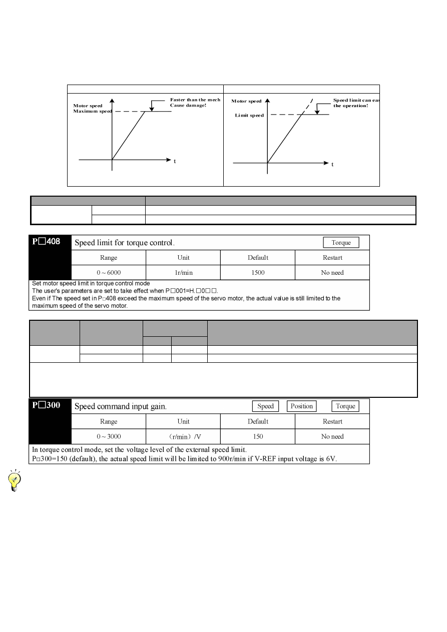
5.7.4 Speed limit for torque control

As servo motor should be controlled in torque control to output the torque issuing instructions, motor speed management is not

implemented.

If too high instruction torque is set relatively to the load torque of the machinery side, it exceeds machinery torque, resulting in

remarkable increase of motor speed.

As the protective measure of the machinery side, it is equipped with the function to limit the speed of servo motor during torque

control.

No speed limit

Speed limit

(1) Choice of speed control mode (torque limit option)

User parameters

Significance

P

001

H.

0

□□

Take the P

408 set value as the speed limit. (Internal speed limit function)

H.

1

□□

V-REF is used as external speed limit input.

(2) Internal speed limit function

(3) External speed limit function

Category

Signal name

Connector Pin

number

Name

A axis

B-axis

Input

V-REF

CN1-5 CN1-30

External speed limit input

GND

CN1-6 CN1-31

Signal ground

The motor revolving speed limit when using input torque limit with analog voltage instruction.

When P

001=H.

1

□□,

the smaller value is the valid value between the speed limit input of V-REF and the speed limit of

P

408 “Torque control speed limit”

The set value of P

300 determines the voltage electrical level of limit input. It has nothing to do with polarity.

-------------------------------------------------------------------------------------------------------------------------------------------------------------------------------

■ The principle of speed limit

Negative feedback is conducted to the torque in proportion to the speed difference of speed limit beyond the scope of speed limit,

so as to return to the speed limit scope. Therefore, the limit value of the actual motor speed will vary from the load condition.

-------------------------------------------------------------------------------------------------------------------------------------------------------------------------------

- 85 -

5.8 Speed control (internal speed selection) operation

·

The definition of internal setting speed selection

The selection of internal setting speed is achieved via setting 3 kinds of motor speed through the internal user parameters of the

servo drive, and furthermore, the speed is selected via external input signal to achieve the function of speed control. If running

speed is within 3 kinds of motor speed, speed control is valid.

It is unnecessary to configure speed generator or pulse generator externally.

5.8.1 User parameters setting

User parameters

Significance

P

000

H.

□□

3

Control method choice: internal set speed control (contact instruction)

5.8.2 Input signal setting

Category

Signal name

Connector Pin number

Name

A axis

B-axis

Input

/P-CON

CN1-15

CN1-40

Servo motor rotation direction switching

/PCL

It is need to be allocated

Selection of internal setting speed

/NCL

It is need to be allocated

Selection of internal setting speed

■ On input signal selection

Uniaxial drive: /PCL, /NCL are allocated to CN1-41 and CN1-42 respectively when they are leaving the factory.

Biaxial drive: /PCL, /NCL shall be allocated via the parameters of P

510.

·

The operation mode of three input signals of /P-CON, /P-CL, /N-CL (It is set as the pin that has been allocated when it left

the factory.)

- 86 -

5.8.3 Internal set speed operation

It can be run through internal setting by using the ON/OFF combination of the following input signals.

Input signals

Direction of

motor rotation

/P-CON

/PCL

/NCL

OFF(H)

OFF(H)

OFF(H)

Forward

Stop the internal speed by instruction 0

OFF(H)

ON(L)

P

301

internal set speed 1(SPEED1)

ON(L)

ON(L)

P

302

internal set speed 2(SPEED2)

ON(L)

OFF(H)

P

303

internal set speed 3(SPEED3)

ON(L)

OFF(H)

OFF(H)

Reversal

Stop the internal speed by instruction 0

OFF(H)

ON(L)

P

301

internal set speed 1(SPEED1)

ON(L)

ON(L)

P

302

internal set speed 2(SPEED2)

ON(L)

OFF(H)

P

303

internal set speed 3(SPEED3)

(Note) signal OFF(H electrical level)

signal ON(L electrical level)

-----------------------------------------------------------------------------------------------------------------------------------------------------------------------------

■ When control method is switching mode

When P

000.1 = 4

5

6

If anyone signal of /PCL

/NCL is set as OFF(H electrical level)

then switch the control mode in between.

For example)P

000.1=5

Set the internal setting speed; choose setting speed



position control (pulse train)

Input signals

Operating speed

/PCL

/NCL

OFF(H)

OFF(H)

Stop the internal speed by instruction 0

OFF(H)

ON(L)

P

301

internal set speed 1(SPEED1)

ON(L)

ON(L)

P

302

internal set speed 2(SPEED2)

ON(L)

OFF(H)

P

303

internal set speed 3(SPEED3)

-----------------------------------------------------------------------------------------------------------------------------------------------------------------------------

·

Practical example based on the selection of internal speed setting

If the soft start function is used, the impact of the speed switching will be smaller.

For soft starting, please refer to "soft start".

Example) Based on internal setting speed + soft start running practical example

- 87 -

--------------------------------------------------------------------------------------------------------------------------------------------------------------------------------

Setting of “(P

000.1 = 5 internal set speed control



position control)”

soft start function is only working when choose the

internal setting speed”. The soft start function cannot be used when the pulse instruction is inputting. It will switch to the input of

pulse command whether it is running at any one of first ~ third speed. Then the servo drive accepts the pulse command after the

position of the output signal (/COIN) output. Please make sure to start output the user instruction controller's pulse instruction after

the position of the servo drive completes the signal output.

Based on the (internal setting speed + soft starting)



position control (pulse train instruction operation practical example)

(Note) 1. As shown in the above figure, the conditions of using the soft start function.

2. The t1 value will not be affected by the using of the soft start.

Reading of /PCL and /NCL may have maximum 2ms delay.

-------------------------------------------------------------------------------------------------------------------------------------------------------------------------------

5.9 Torque limit

For the purpose of protecting the machinery and other purposes, the output torque shall be limited. There are 4 kinds of torque limit

methods for the servo drive.

Method

Restriction mode

Reference

1

Internal torque limit

2

External torque limit

3

Torque limit based on analog voltage instruction

4

Based on external torque limit + Torque limit

based on analog voltage instruction

5.9.1 Internal torque limit (maximum output torque limit)

Internal torque limit is the function of limiting the maximum output torque via user's parameters.

- 88 -

5.9.2 External torque limit (external torque limit via input signal)

External torque limit is used while the machine is running or when certain torque is required. For example, it is used for pressing

stop action or to maintain the robot's work piece.

The torque limit set in the user parameters in advance is changed to be valid by the input signal.

(1) The related user parameters

(Note) the setting unit is % of the rated torque relative to the servo motor used. (The limit of the rated torque is 100 %.)

(2) Input signals

Category

Signal

name

Connector Pin

number

Setting

Significance

Limit value

A axis

B-axis

Input

/PCL

Single/biaxial drive

are different

ON =L electrical

level

Forward external torque

limit ON

One of the smaller values

in Pn403 and Pn405

OFF=H

electrical level

Forward external torque

limit OFF

Pn403

Input

/NCL

Single/biaxial drive

are different

ON =L electrical

level

Reversal external

torque limit ON

One of the smaller values

in Pn404 and Pn406

OFF=H

electrical level

Reversal external

torque limit OFF

Pn404

Uniaxial drive: /PCL, /NCL are allocated to IN7 and IN8 respectively when they are leaving the factory.

Biaxial drive: /PCL, /NCL shall be allocated via the parameters of P

510.

Please make sure that other signals are assigned to the same terminals as /P-CL and /N-CL when using external torque limit.

It becomes OR logic as the multiple signals are allocated to one terminal, therefore, it will be affected by other signals

ON/OFF assigned to the same terminal. For the distribution of input signals, please refer to the "Signal distribution of the

input circuit".

(3) Change of output torque of external torque is limited

The internal torque limit (P

403

P

404)=300%

/PCL(Forward external torque limit)

H electrical level

L electrical level

/NCL

(Reversal

external

torque limit)

H

electrical

level

L

electrical

level

(Note) in the setting of

P□000=H.□□□ 0

(standard setting [set CCW as forward direction] selects the motor rotation direction.

- 89 -

5.9.3 Torque limit based on analog voltage instruction

Function of arbitrary torque limit by analog voltage instruction. T-REF is used as analog voltage instruction input terminal. Hence,

the function cannot be used for torque control. It can only be used in speed control or position control.

Using block diagram of "torque limit by analog voltage instruction” in the case of speed control is shown in the figure below.

-----------------------------------------------------------------------------------------------------------------------------------------------------------------------------

The input voltage of the analog voltage instruction for the torque limit is non polar.

The absolute values are taken in both + and - voltage, and the torque limit based on the absolute value is applied to both forward

and reverse rotation directions.

-----------------------------------------------------------------------------------------------------------------------------------------------------------------------------

(1) The related user parameters

User parameters

Significance

P

001

H.

□□

1

Speed control option: use T-REF terminal as an external torque limit input.

If set to H.

□□

2

□,

then T-REF terminal can be used for torque feed forward input and please be noted that you cannot use

them simultaneously.

(2) Input signals

Category

Signal name

Connector Pin

number

Name

A axis

B-axis

Input

T-REF

ANA2+

Not

allocated

Torque instruction input

GND

ANA2-

Signal ground

Use P

400 to set torque command input gain. Please refer to "user parameters setting".

- 90 -

5.9.4 Torque limit by external torque limit + analog voltage instruction.

The torque limit via the external input signal and the torque limit through the analog voltage instruction can be used simultaneously.

The analog voltage instruction is used for torque limit from T-REF input. Therefore, it cannot be used when the torque is limited.

When external input signal for torque limit, use /P-CL and /N-CL.

If /P-CL (or /N-CL) signal is set at ON, then use the analog voltage command torque limit and the set value of P

405 (or P

406)

the smaller value shall be limit in torque.

(1) The related user parameters

User parameters

Significance

P

001

H.

□□

3

Speed control options: /P-CL, /N-CL take effect, uses the T-REF terminal as an external

torque limit input.

If set to H.

□□

2

□,

then T-REF terminal can be used for torque feed forward input and please be noted that you cannot use

them simultaneously

(2) Input signals

Category

Signal name

Connector Pin

number

Name

A axis

B-axis

Input

T-REF

ANA2+ Not

allocated

Torque instruction input

GND

ANA2-

Signal ground

Use P

400 to set torque command input gain. Please refer to "user parameters setting".

Category

Signal name

Connector Pin

number

Setting

Significance

Limit value

A axis

b-axis

Input

/PCL

Single biaxial

drive are different

ON =L

electrical level

Forward external

torque limit ON

One of the smaller values

in Pn403 and Pn405

OFF=H

electrical level

Forward external

torque limit OFF

Pn403

Input

/NCL

Single biaxial

drive are different

ON =L

electrical level

Reversal external

torque limit ON

One of the smaller values

in Pn404 and Pn406

OFF=H

electrical level

Reversal external

torque limit OFF

Pn404

Uniaxial drive: /PCL, /NCL are allocated to IN7 and IN8 respectively when they are leaving the factory.

Biaxial drive: /PCL, /NCL shall be allocated via the parameters of P

510.

Please make sure that other signals are assigned to the same terminals as /P-CL and /N-CL when using external torque

limit + analog voltage instruction torque limit.

It becomes OR logic as the multiple signals are allocated to one terminal, therefore, it will be affected by other signals

ON/OFF assigned to the same terminal. For the distribution of input signals, please refer to the "Signal distribution of the

input circuit".

- 91 -

5.9.5 Confirmation of output torque limit

Category

Signal name

Connector pin number

(leave factory)

Setting

Significance

A axis

B-axis

Output

/CLT

It is need to be allocated

ON =L electrical

level

Motor output torque is limited

OFF=H

electrical level

It is not in the torque limit state

In order to use the motor output torque limit signal, the output terminal must be distributed through the user parameter of

P□514. Please refer to the "signal distribution of the output circuit".

5.10 Control mode switching

The servo drive can be used in various control modes.

The switch method and conditions are described below.

5.10.1 User parameters setting

The following combination of control method can be chosen. Please use it according to the customer's use.

User parameters

Significance

P

000

H.

□□4□

The internal setting speed control (DI instruction)←→ speed control (analog instruction)

H.

□□

5

The internal setting speed control (DI instruction)←→ speed control (pulse train instruction)

H.

□□

6

The internal setting speed control ( DI instruction)←→ torque control (analog instruction)

H.

□□

7

Position control (pulse train instruction)←→ speed control (analog instruction)

H.

□□

8

Position control (pulse train instruction)←→ torque control (analog instruction)

H.

□□

9

Position control (analog instruction)←→ speed control (analog instruction)

H.

□□

A

Speed control (analog instruction)←→ Zero clamping position

H.

□□

B

Position control (pulse train instruction) ←→ position control (pulse prohibition)

5.10.2 Control mode switching

(1) Switching between internal speed control (P

00.1=4

5

6 )

Category

Signal name

Connector Pin

number

Setting

Significance

A axis

B-axis

Input

/PCL

Single biaxial

drive different

OFF=H

electrical

level

Control mode switching

Input

/NCL

Single biaxial

drive different

OFF=H

electrical

level

Uniaxial drive: /PCL, /NCL are allocated to IN7 and IN8 respectively when they are leaving the factory.

Biaxial drive: /PCL, /NCL shall be allocated via the parameters of P

510.

(2) Switching other than internal speed control (P

000.1=7

8

9

A

B)

Please switch the control mode with the following signal. The control mode is switched as follows according to the signal state.

Category Signal

name

Connector Pin

number

Setting

P□000 setting

A axis

B-axis

H.

□□

7

H.

□□

8

H.

□□

9

H.

□□

A

H.

□□

B

Input

/PCON CN1-IN2 CN1-IN6

ON =L

electrical

level

Speed

Torque

Speed

Zero

clamping

position

Prohibited

OFF=H

electrical

level

Position

Position

Torque

Speed

Position

- 92 -

5.11 Other output signals

Although there is no direct relation with each control way, it is available to specify it in terms of the other output signals.

Please use it according to the customer's machinery protection and other purpose.

5.11.1 Servo alarm output (ALM)

(1) Servo alarm output (ALM)

When the servo drive detects the exception it is the signal of the output.

Category

Signal name

Connector pin number

(leave factory)

Setting

Significance

A axis

b-axis

Output

ALM

CN1-

OUT1

CN1-

OUT4

ON =L electrical

level

Servo drives normal state.

OFF=H

electrical level

Servo drive alarm state

■ Important

It is necessary to ensure that the main circuit power supply of the servo drive is set OFF in the case of alarm output, when

the external circuit is formed.

(2) Alarm reset

Category

Signal name

Connector pin number

(leave factory)

Name

A axis

b-axis

Input

/ALM-RST

Single biaxial drive are

different

Uniaxial drive: /PCL, /NCL are allocated to IN7 and IN8 respectively when they are leaving the factory.

Biaxial drive: /PCL, /NCL shall be allocated via the parameters of P

510.

The signal can be assigned to other pin number via the user parameter P

510. For detail, please refer to the "signal

distribution of the input circuit".

/ALM-RST signal is set by the allocation of the external input signal; therefore, it cannot be set as "constant time effective".

Please make use of an action from the H electrical level to the L electrical level to reset the alarm.

When "servo alarm (ALM)" occurs, eliminate the cause and the alarm state can be reset by placing the signal (/ALM-RST)

from OFF (H electrical level) to ON (L electrical level).

Moreover, the alarm reset can also be operated by the panel operator or the digital operator. Please refer to the "Name and

function of the key".

----------------------------------------------------------------------------------------------------------------------------------------------------------------------

1. The encoder alarm sometimes input /ARM-RST signal still cannot be reset. In this case, please reset it by power off the control

power.

2. When the alarm occurs, please make sure to reset the alarm after the alarm is excluded.

The "Alarm display and processing measures" has been described in the troubleshooting method of the alarm.

----------------------------------------------------------------------------------------------------------------------------------------------------------------------

5.11.2 Rotation detection output (/TGON)

Category

Signal name

Connector pin number

(leave factory)

Setting

Significance

A axis

B-axis

Output

/TGON

Need P

513 allocation

ON =L

electrical level

The servo motor is rotating (motor

revolving speed is greater than the set

value of P

502)

OFF=H

electrical level

Servo motor stop rotating (motor speed is

higher than the set value of P

502)

■Important

The brake signal (/BK) and rotation detection signal (/TGON) are allocated to the same output terminal, due to falling on the

vertical axis speed, the /TGON signal becomes L electrical level, but the /BK signal may not change to H electrical level.

(As the output signals are assigned to the same output terminal to output the OR logic), please allocate (/TGON) signals

and (/BK) signals to other terminals.

5.11.3 Servo ready output (/S-RDY)

Category

Signal name

Connector pin number

(leave factory)

Setting

Significance

A axis

B-axis

Output

/S-RDY

Need P

513 allocation

ON =L

electrical level

Servo ready status

OFF=H

electrical level

Servo not ready status

It indicates that the servo unit has been in the servo ON signal ready state for receiving.

The main circuit output is in the state of ON without servo alarm.

- 93 -

5.12 Mode motion sequence mode

15 sets of data groups are supported by the product, which can set parameters in the parameter mode. In the communication mode,

32 sets of data can be used to set parameters. These data groups may start individually or in sequence.

It contains setting for data group types and the setting of related target values and subsequent data groups in the data group of set

parameters

The following types of movement are available:

• Invalid movement (empty data)

• Absolute movement

• Relative movement

The data group may start in 2 different ways.

• Start single data group

Only the selected data group starts when a single data group is starting. No other data groups will start after the

successful execution of the data group. Time coordination between multiple data groups is accomplished through the

main control system (such as PLC).

• Start the sequence of data groups (multiple data groups are arranged in turn)

It starts from the selected data group when the sequence starts. The subsequent data group will start when a data group

is successfully executed and the transition condition is satisfied. The time coordination between each data group is

completed through the product.

5.12.1 Single data group mode

The single data group mode adopts with 15 sets of built-in motion tasks. The incremental or absolute type may be chosen for the

form of motion.

(1) User parameters setting

User parameters

Significance

P

000

H.

□□

C

Choice of control mode: mode motion sequence mode

P

764

H.

□□□

0

Startup data group mode selection: single data group mode

- 94 -

(2) Input signal setting

Category

Signal name

Connector Pin number

Name

A axis

B-axis

Input

/POS-START

Need P

512 allocation

Mode motion sequence starting signal

Input

/POS-STEP

Need P

512 allocation

Mode of motion sequence change step signal

Input

/POS0

Need P

511 allocation

Mode motion sequence data group select switch 0 signal

Input

/POS1

Need P

511 allocation

Mode motion sequence data group select switch 1 signal

Input

/POS2

Need P

511 allocation

Mode motion sequence data group select switch 2 signal

Input

/PCON

Need P

509 allocation

Mode motion sequence data group select switch 3 signal

When it is single data group mode and the /POS-START signal is ON, the motor operation is allowed; when it is OFF, the

motor operation is suspended.

Input signals (/POS-START, /POS-STEP, /POS0, /POS1, /POS2, /PCON) can choose 15 sets of data group s as the data group to

be executed at the moment, as shown in the following table.

Data group

/POS2

/POS1

/POS0

/POS-START /POS-STEP

Corresponding parameters

P0

OFF

OFF

OFF

ON

P

700 ~ P

703

P1

OFF

OFF

ON

ON

P

708 ~ P

711

P2

OFF

ON

OFF

ON

P

716 ~ P

719

P3

OFF

ON

ON

ON

P

724 ~ P

727

P4,

ON

OFF

OFF

ON

P

732 ~ P

735

P5

ON

OFF

ON

ON

P

740 ~ P

743

P6

ON

ON

OFF

ON

P

748 ~ P

751

P7

ON

ON

ON

ON

P

756 ~ P

759

The sequence diagram between the input signal and the data group is as follows:

- 95 -

- 96 -

5.12.2 Data group sequence mode

The data group sequence supports 8 groups of data groups in the parameter mode, and supports up to 32 groups of data groups in

the communication mode. The incremental or absolute type may be chosen for the form of motion.

(1) User parameters setting

User parameters

Significance

P

000

H.

□□

C

Choice of control mode: mode motion sequence mode

P

764

H.

□□□

1

Starting data group mode selection: task mode (data group sequence)

User parameters

Significance

P

704

H.

□□□

0

No step change, directly start the subsequent data group; the second step changing

condition is invalid.

H.

□□□

1

Delay step change, delay time of the data group "1 value step change conditions"

H.

□□□

2

For the change step of pulse edge, the "change step condition 1 value" in the data group

determines the rising edge or falling edge, which is valid.

H.

□□□

3

The "change step condition 1" in the data group determines whether the high level or low

level is effective.

User parameters

Significance

P

704

H.

□□

0

No step change, directly start the subsequent data group;

H.

□□

1

No step change, directly start the subsequent data group;

H.

□□

2

For the change step of pulse edge, the "change step condition 2 value" in the data group

determines whether the rising edge or falling edge is effective.

H.

□□

3

The "change step condition 2" in the data group determines whether the high level or low

level is effective.

- 97 -

User parameters

Significance

P

704

H.

0

□□

No connection, step change 2 conditions is invalid.

H.

1

□□

"And” connection between Condition 1 and condition 2.

H.

2

□□

"Or” connection between Condition 1 and condition 2.

User parameters

Significance

P

704

H.0

□□□

Aborting: ignore the step change condition, immediately stop motion, and start the

subsequent data group.

H.1

□□□

Standard: the current motion is in place and the step change condition is satisfied, and

then, start the subsequent data group.

H.2

□□□

Buffered: reaches the target position and step change condition is satisfied and start the

subsequent data group.

H.3

□□□

Blending Low: ignore the step change conditions. Speed is adjusted at the speed of the

subsequent data group when the target is reached.

- 98 -

H.4

□□□

Blending Previous: Ignore the step change conditions. Speed is adjusted at the speed of

the subsequent data group when the target is reached.

H.5

□□□

Blending Next: ignore the step change conditions. Speed is adjusted at the speed of the

subsequent data group when the target is reached.

H.6

□□□

Blending High: ignore the step change conditions. Speed is adjusted at the speed of the

subsequent data group when the target is reached.

- 99 -

(2) Input signal setting

Category

Signal name

Connector Pin

number

Name

A axis

B-axis

Input

/POS-START

Need P

512 allocation Mode motion sequence starting signal

Input

/POS-STEP

Need P

512 allocation Mode of motion sequence change step signal

/POS-START signal from OFF

ON

When it is ON

motor operation is allowed

When it is OFF

motor running will

pause.

■Important

After each servo OFF (or alarm solution), the /POS-START signal is first set from ON to OFF before it is restarted, and then

set to ON to start loading data group.


Content      ..     4      5      6      7     ..