HSD3 Series AC Servo Drive. User's Manual (Version: 3.1.14) - page 4
- 52 -
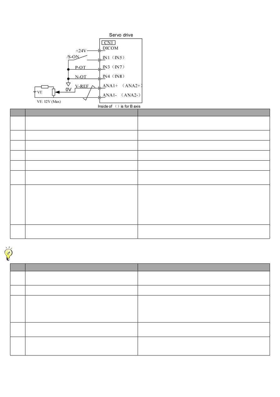
(2) Operation steps of speed control mode
(
P
□
000=H.
□□
0
□)
The following external input signal circuit and the equivalent signal circuit shall be configured.
Step
Content
Confirmation method and supplementary description
1
Please confirm the power and input signal circuit again
and verify the speed instruction input (the voltage
between V-REF and GND) is 0V.
Please refer to the input signal circuit shown in the above figure.
2
Please set the servo ON (/S-ON) input signal ON.
If the servo motor makes tiny rotation, please reference "adjustment
of instruction offset" for the non-rotation setting of servo motor.
3
Please input the speed instruction (the voltage between
V-REF and GND) slowly increase from 0V.
Default factory is 150(r/min)/V.
4
Please confirm that the speed instruction value
(Un004[r/min]) input to the servo drive.
For the display method, please refer to “Basic mode of selection and
operation”
5
Please confirm the servo motor speed (Un000[r/min])
value.
For the display method, please refer to “Basic mode of selection and
operation”
6
Please confirm that value of step 4 is equal to the step 5
(Un004 and Un000).
For speed change instruction, input voltage to confirm whether
Un004=Un000 is achieved under the mode of multiple speed
instruction values.
7
Please confirm the input gain of speed instruction or the
direction of motor rotation.
If input gain (P□300) is conducted to the speed change instruction,
please reference the following formula.
Un004
=
P□300[rpm/V]×(V-REF voltage)[V]
If you want to change the direction of motor rotation under the
condition of keeping the input voltage polarity of the speed
instruction, please reference the "switching for the direction of motor
rotation".
Please start execution from step 2 after change. → check from
step 2 again.
8
If it gets into servo OFF status when speeds input
instruction is set as 0V, it shows the test run completion of
the servo motor unit.
-----------------------------------------------------------------------------------------------------------------------------------------------------------------------------------
Position control is configured on the instruction control unit
When servo is placed in speed control and position control is configured on the instruction control unit, please confirm the following
items after the above "operating steps of speed control mode".
Step
Content
Confirmation method and supplementary description
9
Please confirm the power and input signal circuit again
and verify the speed instruction input (the voltage
between V-REF and GND) is 0V.
10
Please set the servo ON (/S-ON) input signal ON.
If the servo motor makes tiny rotation, please reference "adjustment
of instruction offset" for the non-rotation setting of servo motor.
11
Issue the instruction of the motor rotation amount (e.g.,
motor rotates 1 circle) easy to be confirmed in advance
from the instruction control unit, and confirm the issued
motor rotation amount and the rotated motor rotation
amount via visual inspection and motor's real angle
monitoring (Un015[pulse]).
Motor rotation angle 1 (Un015 [pulse]): number of pulses starting
from the origin.
12
Whether the rotation value of step 11 is different, please
set the PG frequency ratio (Pn201) of the output encoder
pulse from the servo unit correctly.
Please refer to the "Encoder signal output” for the setting method.
PG frequency ratio (Pn201[P/Rev]): the number of encoder pulses
per rotation for 1 cycle.
13
Enter the servo into OFF state when the speed input
instruction is set at 0V, and then it is indicated that the trial
running of the command controller as position control has
been completed.
-------------------------------------------------------------------------------------------------------------------------------------------------------------------------------
(3) Operation steps of position control mode
(
P
□
000=H.
□□
1
□)
The following external input signal circuit and the equivalent signal circuit shall be configured.