HSD3 Series AC Servo Drive. User's Manual (Version: 3.1.14) - page 2
 

  Index      Manuals     HSD3 Series AC Servo Drive. User's Manual (Version: 3.1.14)


Search            copyright infringement  


Content      ..      1      2      3      ..


HSD3 Series AC Servo Drive. User's Manual (Version: 3.1.14) - page 2


- 20 -

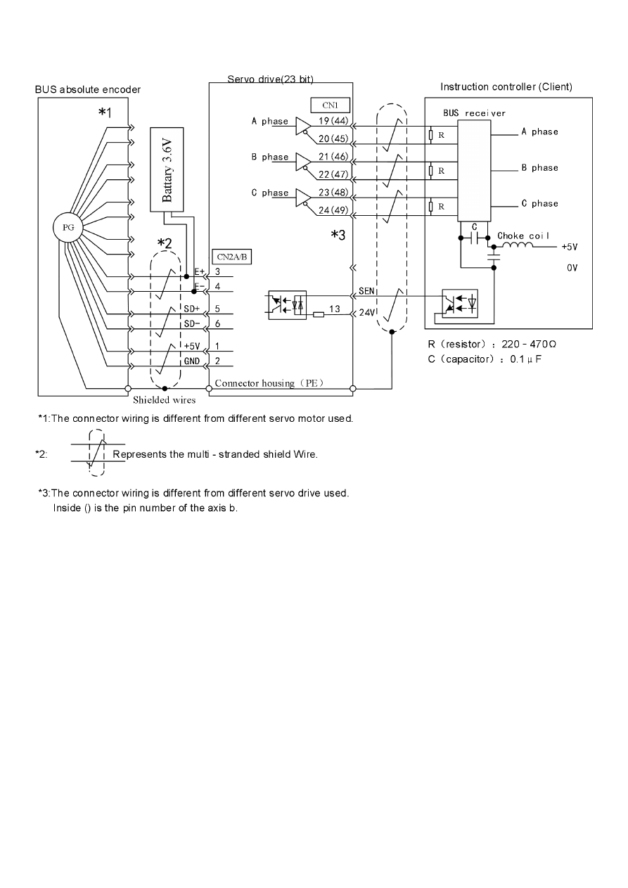
(4) Bus absolute value encoder
- 21 -

3.3 Input and output signal wiring

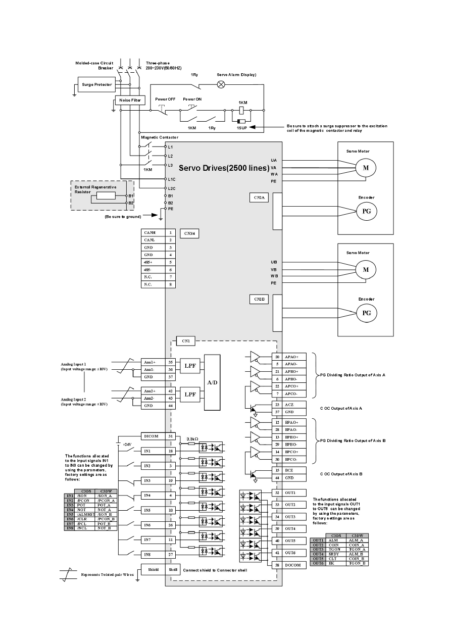
3.3.1 Speed / torque control mode (2500 line)

- 22 -

3.3.2 Position control mode (2500 line)

- 23 -

3.3.3 Speed / torque control mode (23 bits)

- 24 -

3.3.4 Position control mode (23 bits)

- 25 -

3.3.5 Input and output connector CN1 signal name and its function (2500 line)

Te

rm

in

al

nu

m

be

r

Name

Function

Te

rm

in

al

nu

m

be

r

Name

Function

Uniaxial drive

Biaxial drive

Uniaxial drive

Biaxial drive

1

APULS+

Command pulse input

A axis command pulse

input

8

BPULS+

Reserve

B axis command pulse input

16

APULS-

24

BPULS-

2

ASIGN+

Command symbol input

A axis command symbol

input

9

BSIGN+

Reserve

B axis command symbol

input

17

ASIGN-

25

BSIGN-

18

IN1

The output port 1, which

can be redistributed

(leave the factory as

/S-ON)

The output port 1, which

can be redistributed

(leave the factory as

A

axis /S-ON)

10

IN5

The output port 5, which can be

redistributed

(leave the factory as

/ALM-RST)

The output port 5, which can

be redistributed

(leave the factory as

b axis

/S-ON)

3

IN2

The output port 2, which

can be redistributed

(leave the factory as

/P-CON)

The output port 2, which

can be redistributed

(leave the factory as

A

axis /P-CON)

26

IN6

The output port 6, which can be

redistributed

(leave the factory as

/CLR)

The output port 6, which can

be redistributed

(leave the factory as

b axis

/P-CON)

19

IN3

The output port 3, which

can be redistributed

(leave the factory as

POT)

The output port 3,which

can be redistributed

(leave the factory as

A

axis POT)

11

IN7

The output port 7, which can be

redistributed

(leave the factory as

/PCL)

The output port 7, which can

be redistributed

(leave the factory as

b axis

POT)

4

IN4

The output port 4, which

can be redistributed

(leave the factory as

NOT)

The output port 4, which

can be redistributed

(leave the factory as

A

axis NOT)

27

IN8

The output port 8, which can be

redistributed

(leave the factory as

/NCL)

The output port 8, which can

be redistributed

(leave the factory as

b axis

NOT)

32

OUT1

The output port 1, which

can be redistributed

(leave the factory as

ALM)

The output port 1, which

can be redistributed

(leave the factory as

A

axis ALM)

39

OUT4

The output port 4, which can be

redistributed

(leave the factory as

/S-RDY)

The output port 4, which can

be redistributed

(leave the factory as

b axis

ALM)

33

OUT2

The output port 2, which

can be redistributed

(leave the factory as

/COIN)

The output port 2, which

can be redistributed

(leave the factory as

A

axis /COIN)

40

OUT5

The output port 5, which can be

redistributed

(leave the factory as

/CLT)

The output port 5, which can

be redistributed

(leave the factory as

b axis

/COIN)

34

OUT3

The output port 3, which

can be redistributed

(leave the factory as

/TGON)

The output port 3, which

can be redistributed

(leave the factory as

A

axis /TGON)

41

OUT6

The output port 6, which can be

redistributed

(leave the factory as

/BK)

The output port 6, which can

be redistributed

(leave the factory as

b axis

/TGON)

31

DICOM

Input signal public end

Input signal public end

38

DOCOM

Output signal public terminal

Output signal public terminal

21

APAO+

PG frequency division

output A phase

A axis PG frequency

division output A phase

12

BPAO+

Reserve

B axis PG frequency division

output A phase

5

APAO-

28

BPAO-

22

APBO+

PG frequency division

output B phase

A axis PG frequency

division output B phase

13

BPBO+

Reserve

B axis PG frequency division

output B phase

6

APBO-

29

BPBO-

23

APCO+

PG frequency division

output C phase

A axis PG frequency

division output C phase

14

BPCO+

Reserve

B axis PG frequency division

output C phase

7

APCO-

30

BPCO-

23

ACZ

C phase collector open

circuit output

A axis C collector open

circuit output

15

BCZ

Reserve

B axis C collector open

circuit output

35

AnIN1+

Speed command input

A axis command Input

42

AnIN2+

Torque command Input

B axis speed command

Input

36

AnIN1-

43

AnIN2-

37

GND

Signal ground

Signal ground

44

GND

Signal ground

Signal ground

(Note) 1. Empty terminal, do not use it.

2. Please connect the shielded wire for input/output signal cable to the connector shell.

3. The function distribution change of the following input/output signal can be achieved via the setting of user preferences.

Output: OUT1, OUT2, OUT3, OUT4, OUT5, OUT6

The above output opening can be changed to ALM, /COIN, /TGON, /S-RDY, /CLT, /BK of the A axis or B axis via the parameters.

Input: IN1, IN2, IN3, IN4, IN5, IN6, IN7, IN8

The above input opening can be changed to /S-ON, /P-CON, POT, NOT, /ALM-RST, /CLR, /PCL, /NCL, /GSEL, signals of the A

axis or B axis via the parameters.

4. The terminal definition and wiring on CN1 and MODBUS (RS485) protocol is only valid for model 00 (Pulse/Analog), they’re not

valid for other models which use communication protocol.

- 26 -

3.3.6 Input and output connector CN1 signal name and its function (23 bits)

Te

rm

in

al

nu

m

be

r

Name

Function

Te

rm

in

al

nu

m

be

r

Name

Function

Uniaxial drive

Biaxial drive

Uniaxial drive

Biaxial drive

1

APULS+

Command pulse input

A axis command pulse

input

26

BPULS+

Reserve

b axis command pulse

input

2

APULS-

27

BPULS-

3

ASIGN+

Command symbol input

A axis command

symbol input

28

BSIGN+

Reserve

b axis command symbol

input

4

ASIGN-

29

BSIGN-

5

AnIN1+

Speed command input

A axis command Input

30

AnIN2+

Torque command Input

b axis speed command

Input

6

AnIN1-

31

AnIN2-

7

OUT1+

The output port 1, which

can be redistributed

(leave the factory as

ALM)

The output port 1, which

can be redistributed

(leave the factory as

A

axis ALM)

32

OUT4+

The output port 4, which can

be redistributed

(leave the factory as

/S-RDY)

The output port 4, which

can be redistributed

(leave the factory as

b

axis ALM)

8

OUT1-

33

OUT4-

9

OUT2+

The output port 2, which

can be redistributed

(leave the factory as

/COIN)

The output port 2, which

can be redistributed

(leave the factory as

A

axis /COIN)

34

OUT5+

The output port 5, which can

be redistributed

(leave the factory as

/CLT)

The output port 5, which

can be redistributed

(leave the factory as

b

axis /COIN)

10

OUT2-

35

OUT5-

11

OUT3+

The output port 3, which

can be redistributed

(leave the factory as

/TGON)

The output port 3, which

can be redistributed

(leave the factory as

A

axis /TGON)

36

OUT6+

The output port 6, which can

be redistributed

(leave the factory as

/BK)

The output port 6, which

can be redistributed

(leave the factory as

b

axis /TGON)

12

OUT3-

37

OUT6-

13

DICOM

Input signal public end

Input signal public end

38

NULL

Reserve

Reserve

14

IN1

The output port 1, which

can be redistributed

(leave the factory as

/S-ON)

The output port 1, which

can be redistributed

(leave the factory as

A

axis /S-ON)

39

IN5

The output port 5, which can

be redistributed

(leave the factory as

/ALM-RST)

The output port 5, which

can be redistributed

(leave the factory as

b

axis /S-ON)

15

IN2

The output port 2, which

can be redistributed

(leave the factory as

/P-CON)

The output port 2, which

can be redistributed

(leave the factory as

A

axis /P-CON)

40

IN6

The output port 6, which can

be redistributed

(leave the factory as

/CLR)

The output port 6, which

can be redistributed

(leave the factory as

b

axis /P-CON)

16

IN3

The output port 3, which

can be redistributed

(leave the factory as

POT)

The output port 3, which

can be redistributed

(leave the factory as

A

axis POT)

41

IN7

The output port 7, which can

be redistributed

(leave the factory as

/PCL)

The output port 7, which

can be redistributed

(leave the factory as

b

axis POT)

17

IN4

The output port 4, which

can be redistributed

(leave the factory as

NOT)

The output port 4, which

can be redistributed

(leave the factory as

A

axis NOT)

42

IN8

The output port 8, which can

be redistributed

(leave the factory as

/NCL)

The output port 8, which

can be redistributed

(leave the factory as

b

axis NOT)

18

NULL

Reserve

Reserve

43

NULL

Reserve

Reserve

19

APAO+

PG frequency division

output A phase

A axis PG frequency

division output A phase

44

BPAO+

Reserve

b axis PG frequency

division output A phase

20

APAO-

45

BPAO-

21

APBO+

PG frequency division

output B phase

A axis PG frequency

division output B phase

46

BPBO+

Reserve

b axis PG frequency

division output B phase

22

APBO-

47

BPBO-

23

APCO+

PG frequency division

output C phase

A axis PG frequency

division output C phase

48

BPCO+

Reserve

b axis PG frequency

division output C phase

24

APCO-

49

BPCO-

25

GND

Signal ground

Signal ground

50

GND

Signal ground

Signal ground

Note:

The terminal definition and wiring on CN1 and MODBUS (RS485) protocol is only valid for model 00 (Pulse/Analog), they’re not valid

for other models which use communication protocol.

- 27 -

3.3.7 Interface circuit

The input/output signal of servo unit and its example of connection with instruction control unit are as follows.

(1) The interface with the instruction input circuit

(a) Analog input circuit

Below is the ANA1 (speed instruction input) and ANA2 (torque instruction input) terminal of CN1 connector description.
The analog signal is a speed command or a torque command signal. Input impedance as shown below.

·

Speed instruction input: About 20kΩ

·

Torque instruction input: About 20kΩ
The maximum acceptable voltage of the input signal is

±

12V.

(b) Position instruction input circuit

And then, specify the 1-2(instruction pulse input) and 3-4 (instruction character input) of the CN1 connector.
The instruction pulse input circuit of the instruction control unit side can be selected from any one of the bus driver output and
collector open circuit output, and its classification is as follows.

- 28 -

(2) Interface with the direct control input circuit.

Below is IN1 ~ IN8 terminals of CN1 connector description.
It is connected via the transistor circuit of relay or collector open circuit. When relay is used continuously, please choose the

micro-current relay. If micro-current relay is not used, it causes poor contact.

-----------------------------------------------------------------------------------------------------------------------------------------------------------------------------------

Please refer to the section "the method of use of the absolute value encoder” for the interface of the SEN signal input circuit.

----------------------------------------------------------------------------------------------------------------------------------------------------------------------------------

(3) Absorption loop and release circuit

The input circuit of the servo drive adopts bi-directional opto coupler. Please choose the connection of absorption circuit connection

and the release circuit in accordance with the specifications of the machine.

(4) Interface with the output circuit

(a) Bus driver (differential) output circuit

Below is the description of the A phase signal, B phase signal and C phase signal terminal of CN1 connector.
The serial data of the encoder is converted by two phases (A phase, B phase) and the output signal (PAO, /PAO, PBO, /PBO)

and the origin pulse signal
(PCO, /PCO) is output by the output circuit of the bus driver. Usually, when the servo
unit the position control system is formed on the side of the command controller, the element is used by the speed control. On

the instruction controller side, please use the bus receiver circuit for receiving.

(b) Output circuit of optical point coupler

The servo alarm (ALM), servo readiness (/S-RDY) and the other sequential output signals are made up of the output circuit of

the opto-coupler. And through the relay circuit or the bus receiver circuit for connection.

- 29 -

(Notes) The maximum allowable voltage and current capacity of the photoelectric coupler output circuit are shown below.

·

Maximum voltage: DC30V

·

Maximum current: DC50mA

- 30 -

3.4 Other wiring

3.4.1 Matters need attention for wiring

---------------------------------------------------------------------------------------------------------------------------------------------------------------------------
1. Use the specified cable for instruction input and wiring to encoder.

Please select the cable with the shortest distance.

2. Use thick wires as much as possible for earth wiring (above 2.0mm

2

).

·

Recommended grounding D or more (the value of grounding resistance is 100 Ω or less).

·

It must be grounded.

·

Please connect the servo motor directly to the ground when the servo motor and the machine are insulated from each other.

3. Do not bend the wire or bear the tension.

The core line of the cable for signal is only 0.2mm or 0.3mm, very thin, please careful when using.

4. Please use the noise filter to deal with radio frequency interference.

·

When product is used near resident houses or when you worry about the influence of radio-frequency interference, please
insert noise filter in the plug of power line.

·

As servo unit is a kind of commercial plant, the radio-frequency interference countermeasure is not taken.

5. In order to prevent the false operation caused by noise, the following handling method is effective.

·

Please try to configure the input instruction device and noise filter near the servo unit.

·

Please be sure to install surge suppressor on the coils of the relay, solenoid and electromagnetic contractor.

·

Please separate the power line (strong current circuit of power line, servo motor wiring, etc.) from the signal line during wiring,
and keep a 30cm interval above. Do not put them in a same pipe or bind them together.

·

Do not use a same power supply with electric welding machine, electric discharge machine, etc. Although it is not the same
power supply, and there exists high frequency generator nearby, please insert the noise filter on the input side of the power line.

6. Wiring breaker (QF) or fuse is used for protecting the power line.

·

The servo drive is directly connected on the industrial power line. That is to say, transformer is not used for insulation, in order
to prevent the servo system from producing cross-electric shock accident, please be sure to use the wiring breaker (QF) or
fuse.

7. Servo drive is not internally installed with ground protection circuit. In order to constitute a safer system, please configure the

residual-current circuit breaker with dual purpose of overload/short-circuit protection or the special ground-electrode
residual-current circuit breaker matched with wiring breaker.

------------------------------------------------------------------------------------------------------------------------------------------------------------------------------

- 31 -

3.4.2 Anti-interference wiring

(1) An example of anti-interference distribution

"High-speed switch element" is used for the main circuit of the servo drive. According to the peripheral wiring and grounding
treatment of servo drive, it may be influenced by the switch and noise due to switch element. Therefore, correct grounding method
and wiring treatment are essential.
The servo drive is built in with a microprocessor (CPU). As a result, the "noise filter" needs to be configured in place to prevent
external interference as much as possible.
The following figure is shown as an example of the wiring of the anti-interference measures.

1 For ground wires connected to the casing, use a thick wire with a thickness of at least

3.5mm

2,

(preferably, plain stitch copper wire)

2

: Represents twisted-pair wires

3 when using a noise filter, please follow the “(3) The method of using noise filter

(2) Correct grounding treatment

(a) Grounding of the motor frame
Please be sure to connect the motor frame terminal "FG" of the servo motor with the earthing terminal "PE" of the servo unit. In
addition, the ground terminal "PE" shall be grounded.
When the servo motor is grounded via mechanical way and the switch interference current will flow from the power portion of the
servo unit via the stray capacitance of servo motor.
The above content is the measure to prevent this effect.
(b) When the instruction input line is disturbed
Please connect the 0V line (GND) of the input line to the ground when the instruction input line is disturbed. Please connect the
catheter and its junction box to the ground when the main electric circuit of the motor is passed through the metal pipe.
Please connect the above earth grounding to the ground.

(3) The method of using noise filter

In order to prevent interference from the power line, the blocking filter noise shall be used.
In addition, the power cord of the peripherals shall also be inserted into the noise filter as needed.

------------------------------------------------------------------------------------------------------------

--------------------------------------------

The power supply of brake uses the noise filter

Use the following noise filter at the power input of the brake when using a servo motor with a brake under 400W.

Model: FN2070-6/07 (from SCHAFFNER)

Note for the use of noise filter

Please follow the following precautions when the noise filter is installed and wired. If the error occurred in the using method, the
effect of the noise filter will be greatly reduced.

- 32 -

1. Please separate the input wiring from the output line. Do not put them into the same pipe or bundle together.

2. Separate the ground wire of the noise filter from the output wiring.

Please do not put the noise filter output wiring and other signal lines into the same pipe as the ground wire and do not bind

them together.

- 33 -

3. The ground wire of the filter line is connected to the floor separately. Do not connect to other ground lines.

4. The ground wire of the noise filter in the device.

Please connect the ground wire of the filter to the other mechanical grounding lines on the binding grounding plate, and then

ground it when there is a noise filter in a certain device.

----------------------------------------------------------------------------------------------------------------------------------------------------------------------------------

- 34 -

3.5 Electric motor wiring

3.5.1 Motor encoder with connector terminal wiring.

Bus type 23 bits encoder socket (7 cores):

Terminal number

1

2

3

4

5

6

7

Signal

FG

E-

E+

SD-

GND

SD+

5V

Note:

SD+ and SD- are data output

signals; E+ and E- are battery leads.

Bus type 23 bits encoder socket (17 cores):

Terminal number

J

S

t

L

G

K

H

Signal

FG

E-

E+

SD-

GND

SD+

5V

Note:

SD+ and SD- are data output

signals; E+ and E- are battery leads.

Servo motor 2500 wire incremental encoder socket (9 cores):

Terminal number

2

3

4

7

5

8

6

9

1

Signal

5V

GND

A+

A-

B+

B-

C+

C-

FG

Servo motor 2500 wire incremental encoder socket (17 cores):

Terminal number

H

G

A

B

C

D

E

F

J

Signal

5V

GND

A+

A-

B+

B-

C+

C-

FG

3.5.2 Motor power supply connector terminal wiring

Power socket 1 (4 cores):

Terminal number

1

2

3

4

Title

FG

U

V

W

Power socket 2 (4 cores):

Terminal number

D

A

B

C

Title

FG

U

V

W

Power socket 3 (6 cores):

Terminal number

1

2

3

4

5

6

Title

FG

U

V

W

BK+

BK-

Power socket 4 (9 cores):

Terminal number

E

F

I

B

G

H

Title

FG

U

V

W

BK+

BK-

3.5.3 Motor brake adopts the terminal wiring of the connector

Terminal number

1

2

3

Title

DC power supply (non polar access

requirements)

——

110 Parameters of loss of electric brake in the seat configuration:

Working voltage: 24VDC (-15% ~ +10%), working current: ≤0.6A, the brake torque

≥8Nm

130 Parameters of loss of electric brake in the seat configuration:

Working voltage: 24VDC (-15% ~ +10%), working current: ≤0.6A, the brake torque

≥12Nm

180 Parameters of loss of electric brake in the seat configuration:

Working voltage: 24VDC (-15% ~ +10%), working current: ≤0.8A, the brake torque

≥30Nm

- 35 -

Chapter IV The using method of the panel operator

4.1 Basic operation

Panel operator can be used for the display and operation switch between A axis and b axis, setting of various parameters,
execution of JOG running code, status display, etc. The names and functions of each key are summarized below.

4.1.1 The name and function of the key

Function

key figure

Title

Function

Function

Keys

Switching basic mode: state display, auxiliary function,

parameter setting, monitoring

Long press for switching A axis and B axis display and operation

UP key

Press the UP key to increase the set value

In auxiliary function mode JOG operation, it is used as positive

start.

DOWN key

Press the DOWN key to reduce the set value

In auxiliary function mode JOG operation, it is used as reverse

start

Shift key

Press the key to move the selected bit (The decimal point is

flashing) to the left.

Setting key

Press this button to display the setting and setting value of each

parameter, and enter parameter setting state and the alarm can

be cleared.

In the state display mode, the alarm can be cleared by press the SET key, and the alarm can also be cleared by alarm input
signal /ALMRST.

Note:

please find out the cause of the alarm first and then clear the alarm when the alarm occurs.

4.1.2 The selection and operation of basic mode

The display of running status, parameter setting, running code and other operation can be achieved via switching the basic mode
of the panel operator.
The basic mode includes status display mode, parameter setting mode, monitoring mode and auxiliary function mode. After
pressing the F key, the modes shall be switched in the order shown in the following figure.


Content      ..      1      2      3      ..