HSD3 Series AC Servo Drive. User's Manual (Version: 3.1.14) - page 3
 

  Index      Manuals     HSD3 Series AC Servo Drive. User's Manual (Version: 3.1.14)


Search            copyright infringement  


Content      ..     1      2      3      4      ..


HSD3 Series AC Servo Drive. User's Manual (Version: 3.1.14) - page 3


- 36 -

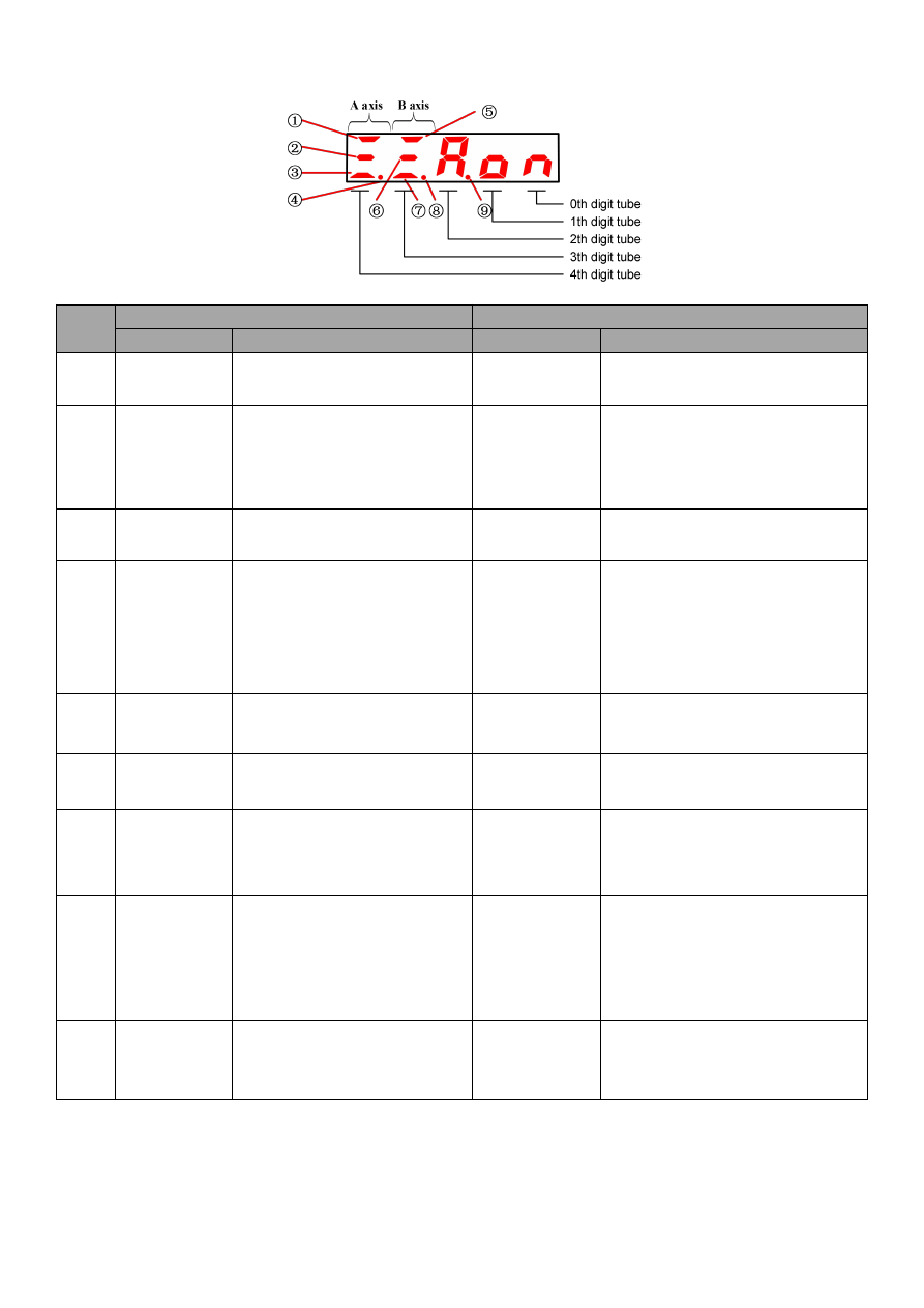
4.1.3 Status display mode

Display content of the bit data

Item

Speed , torque control mode

Position control mode

Bit data

Display content

Bit data

Display content

A axis is

running

Lit when the servo is in ON state.

(electric motor is in the state of

power On position)

A axis is

running

Lit when the servo is in ON state

(electric motor is in the state of powe On

position)

A axis speed

synchronous

/V-CMP

The difference between the motor

speed and the instruction speed is

lower than the specified value

Specified value: PA503

(The factory value is set as 10rpm)

A axis

Positioning

completed

/COIN

Light it when the actual displacement of

the position and

motor position

instruction is less than the specified

value

Specified value: PA500

(The factory value is set as 10 pulse)

A axis

Torque output

Light it when the actual torque of

the motor is 10% beyond the rated

value

A axis

Torque output

Light it when the actual torque of the

motor is 10% beyond the rated value

A axis

forward/reversal

prohibition

The servo is in the limit:

Lighting indicates that it is in the

forward prohibition state

Extinguishing indicates that it is in a

reversal prohibition state

Flicker indicates that it is in a

forward/reversal prohibition state

A axis

forward/reversal

prohibition

The servo is in the limit:

Lighting indicates that it is in the forward

prohibition state

Extinguishing indicates that it is in a

reversal prohibition state

Flicker indicates that it is in a

forward/reversal prohibition state

B-axis is

running

Lit when the servo is in ON state

(electric motor is in the state of On

position)

B-axis is

running

Lit when the servo is in ON state

(electric motor is in the state of On

position)

B-axis

Torque output

Light it when the actual torque of

the motor is 10% beyond the rated

value

B-axis

Torque output

Light it when the actual torque of the

motor is 10% beyond the rated value

B-axis

Rotation

detection

/TGON

The difference between the motor

speed and the instruction speed is

lower than the specified value.

Specified value: PA502

(The factory value is set as 20rpm)

B-axis

Rotation

detection

/TGON

The difference between the motor speed

and the instruction speed is lower than

the specified value.

Specified value: PA502

(The factory value is set as 20rpm)

B-axis

forward/reversal

prohibition

The servo is in the limit:

Lighting indicates that it is in the

forward prohibition state

Extinguishing indicates that it is in a

reversal prohibition state

Flicker indicates that it is in a

forward/reversal prohibition state

B-axis

forward/reversal

prohibition

The servo is in the limit:

Lighting indicates that it is in the forward

prohibition state

Extinguishing indicates that it is in a

reversal prohibition state

Flicker indicates that it is in a

forward/reversal prohibition state

Mains power

supply is

Ready

Light when the main circuit power

supply is in operation

Extinguishing when the main circuit

power supply is off
Mains power

supply is

Ready

Light it when the main circuit power

supply is in operation

Extinguishing when the main circuit

power supply is off

- 37 -

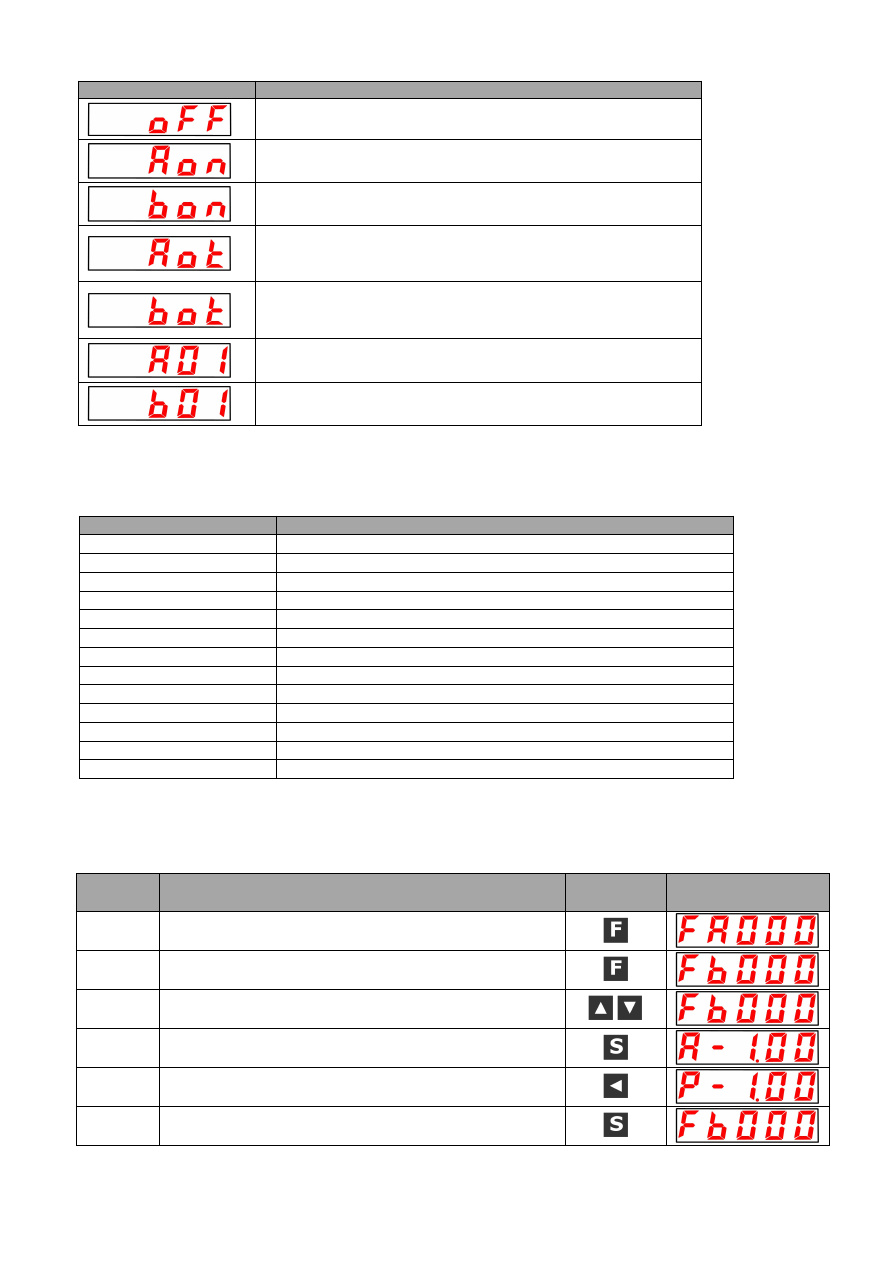
Display content of ellipsis

Ellipsis

Display content

Both A axis and the b axis servo are in the OFF state

(A axis and b axis electric motor is in the state of Off position)
A axis servo is in the ON state

(A axis electric motor is in the state of On position)
b axis servo is in the ON state

(b axis electric motor is in the state of On position)
A axis is in a forward or reversal prohibition state

(It is necessary to judge it according to the positive and reversal

prohibition in the A axis display)
b axis is in a forward or reversal prohibition state

(It is necessary to judge it according to the positive and reversal

prohibition in the b axis display)
A axis alarm state

Alarm number is displayed
b axis alarm state

Alarm number is displayed

4.2 The auxiliary function mode

F

□□□□)

4.2.1 Summary of auxiliary function execution pattern

The operation of the digital operator used for motor operation and adjustment will be described in the section.

The following shows the overview of user parameter and functions of the auxiliary function execution mode.

Auxiliary function number

Function

F□000

Software of the servo

F□001

Position instruction (it is only valid in position mode)

F□002

Jogging (JOG) mode operation

F□003

Identify the percentage of load inertia (relative motor ontology of inertia)

F□004

Verification of the User’s password

F□005

Confirmation of generator model

F□006

Manual adjustment of speed instruction offset

F□007

Manual adjustment of torque instruction offset

F□008

Automatic adjustment of analog quantity (speed, torque) instruction offset

F□009

Clear the multi loop information data of the bus encoder

F□010

Clear the internal error of the bus encoder

F□011

Initialize the user parameter setting value

F□012

Display the historical alarm data

Note:

if it displays "A" in the above table “□” represents that it is in the current A axis auxiliary function mode, and if it

displays "B" represents the current mode for the auxiliary function of B axis.

4.2.2 Servo Software version of displaying

The following is shown the operation steps of the software version of the b axis.

Work

procedure

Work instruction

Action Keys

Post operation display

1

Please press F function key to choose the auxiliary function

mode, and the present situation is A-axis auxiliary function mode.

2

Please press F function key (last more than 1 second), switch to

b axis auxiliary function mode to display the Fb000.

3

Please press UP or DOWN key to select the auxiliary function

Fb000 that you would like to operate.

4

Please press the settings key, if it display A-1.00, it indicate the

processor version is V1.00..

5

Please press down the shift key, if it display P-1.00, it indicate the

FPGA program version is V1.00.

6

press down the settings key to Return to the Fb000 display.

4.2.3 Position teaching operation

The following is shown the operation steps of the position teaching of A axis.

- 38 -

Work procedure

Work instruction

Action Keys Post operation display

1

Please press F function key (last more than 1 second), switch to A axis

auxiliary function mode to display the FA000.

2

Please press UP or DOWN key to select the auxiliary function FA0001 that

you would like to operate.

3

Please press down the setting button to display "2PCLr" and enter the

position teaching operation.

4

Please press down the setting key (last more than 1 second) until the

flicker shows "donE", which indicates the position teaching operation has

been completed successfully.

5

Return to the FA001 display by press down the settings key.

4.2.4 Recognition of the inertia percentage

The following are steps shown the procedure of the percentage of the inertia of A axis by showing the normal mode (clockwise 3

turns, then 3 turns counterclockwise).

Work procedure

Work instruction

Action Keys

Post operation display

1

Please press down F function key and select A axis parameter setting

mode. Press UP key or DOWN key to set the PA127 whether PA127 is not

displayed.

2

Please press the setting button to show "H1341.", and the No. 0 of decimal

point in the current display is flashing.

3

Please press down 3 times shift key, select the third bit of current display,

display "H1.341", and the third decimal point in the current display flashes.

4

Please press down UP key, change the data, and show "H2.341".

5

Return to the upper menu by press down the settings key.

6

Please press F function key to select the auxiliary function FA003 that you

would like to operate.

7

Please press down the setting key to display the inertia recognition

percentage operation interface "-JIn-".

8

Please press F function key, start the inertia recognition operation, and the

motor clockwise turn 3 circles first, and then counter clockwise 3 circles,

blinking display "donE".

9

The percentage of the current detected inertia is displayed after the test is

completed.

——

10

Return to the Fb000 display by press down the settings key.

4.2.5 Confirmation of motor model

It is used for confirming the servo motor type, capacity and encoder model of the servo drive.

Work procedure

Work instruction

Action Keys

Post operation display

1

Please press down F function key and select A axis auxiliary function

mode. Press UP key or DOWN key to set the FA005 if FA005 is not

displayed.

2

“A.0004” is displayed by press down the settings key.

3

Please press down 1 time shift key and display "b.0220".

4

Please press down 1 time shift key and display "C.0010".

5

Please press down 1 time shift key and display "d.0020".

6

“A.0004” is displayed by press down the settings key.

7

Return to the Fb000 display by press down the settings key.

- 39 -

4.2.6 Initialize the user parameter setting value

The following operation steps show the initialization of the user parameters of A axis.

Work

procedure

Work instruction

Action Keys

Post operation display

1

Please press down F function key and select A axis auxiliary
function mode. Press UP key or DOWN key to set the FA011 if
FA011 is not displayed.

2

Entering the parameter initialization operation by press down the
setting key.

3

Please press down the setting key (last more than 1 second) till the
flicker shows "donE", which indicates the initialization of the user
parameters of A axis has been completed successfully.

4

Return to the FA011 display by press down the settings key.

4.2.7 Display the historical alarm data

The maximum 10 past alarms can be identified. The history alarm record will be deleted by the long press setting key. The historical
alarm data cannot be deleted even if the alarm was reset or the servo powered off. In addition, the operation shall not be impacted
the alarm history data itself.

For the alarm content, please refer to the "exception diagnosis and treatment measures".

---------------------------------------------------------------------------------------------------------------------------------------------------------------------------

1. The alarm history data will not be updated if the same alarm occurs continuously.
2. Alarm history data of "A--" or "b--" indicates that no alarm has been reported.

--------------------------------------------------------------------------------------------------------------------------------------------------------------------------

Please follow the following steps to confirm the historical alarm.

Work

procedure

Work instruction

Action Keys

Post operation display

1

Please press down F function key and select A axis auxiliary
function mode. Press UP key or DOWN key to set the FA012 if
FA012 is not displayed.

2

Press down setting key, if it shows “0-A03”, it is the current alarm.

3

Please press down UP key to show the previous 1 historical alarm
(press down to show the next new 1 alarm).

4

If the UP key is pressed down, the alarms shall be displayed by
order.
* "A--" or = "b--" indicates that "no alarm".

5

Return to the Fb012 display by press down the settings key.

- 40 -

4.3 Operation under the user parameters mode

P

□□□□)

Function may be selected or adjusted via setting parameters. There are "parameter setting" and "function selection", two types of

user parameters.

Parameter setting is the function to change the parameter data to be adjusted within a certain range, and function selection is to

choose the functions which have been distributed to the each bit of the panel operator.

4.3.1 User parameters setting

(1) Parameter setting

(a) Type of "parameter setting"

Please refer to the "user parameter list".

(b) Example of changing step of "parameter setting"

The data will be specified directly with numerical values for the parameter setting type user parameters.

The scope of changing can be confirmed by user's parameter list.

Practical example: below is the operation step of changing the b - axis user parameter Pb100 (speed loop gain) from "40" to

"100".

Work

procedure

Work instruction

Action Keys

Post operation display

1

Please press down F function key and select parameter setting

mode.

2

Please press down F function key (last more than 1 second) and

show Pb000. and the No. 0 of decimal point in the current display

are flashing.

3

Please press down 2 times shift key, to select the second bit of

current display, display Pb0.00, and the third decimal point in the

current display flashes.

4

Please press down UP key, change the data, and show Pb1.00.

5

Pb100 current data is displayed by press down the settings key.

6

Please press down 2 times shift key, select the second bit of

current display, shows 000.40 and the second decimal point in the

current display flashes.

7

Please press down UP key, change the data, and show 001.40.

8

Please press down 4 times shift key, select the first bit of current

display, shows "0014.0", and the second decimal point in the

current display flashes.

9

Please press down key, change the data, and show 001.00.

10

Please press down the setting key and return to Pb1.00 so that the

content of the b axis speed loop gain Pb100 is changed from "40"

into "100".

The setting range is above 6 bits

Since the panel operator can only display 5 digits, the setting value beyond 6 bits shall be displayed as follows.

- 41 -

(2) Functional selection

(a) Category of "functional selection”

Please refer to the "User parameters list".

(b) Example of changing step of "functional selection"

Example: the following is the operating step of choosing the control mode (PA000.1) of the basic switch PA000 for A-axis
function, namely, changing from speed control to position control.

Work

procedure

Work instruction

Action Keys

Post operation display

1

Please press F function key (last more than 1 second),
and display PA0.00

2

Press the setting key to show the current data of PA000,
and the No. 0 of decimal point in the current display is
flashing.

3

Please press down 1 time shift key, select the first bit of
current display, shows H000.0

and the first decimal

point in the current display flashes.

4

Please press down UP key, change the data, and
shows H001.0.

5

Return to the PA0.00 display

by press

down the

settings key, so that the A axis control mode is changed
to position control

(c) User parameters in this manual

The user parameters of the function selection are expressed in hexadecimal number, and the each number of setting values
has its own meaning.
The manual adopts the following representation for the user parameters of the function selection.

PA000.0 or A.Hxxx

。。。。。。

It indicates that the value represented by the setting value "0 digit"
of the A axis of user parameter "PA000".

PA000.1 or A.Hxx

x

。。。。。。

It indicates that the value represented by the setting value "1 digit"
of the A axis of user parameter "PA000".

PA000.2 or A.Hx

xx

。。。。。。

It indicates that the value represented by the setting value "2 digit"
of the A axis of user parameter "PA000".

PA000.3 or A.H

xxx

。。。。。。

It indicates that the value represented by the setting value "3 digit"
of the A axis of user parameter "PA000".

Pb000.0 or b.Hxxx

。。。。。。

It indicates that the value represented by the setting value "0 digit"
of the A axis of user parameter "Pb000".

Pb000.1 or b.Hxx

x

。。。。。。

It indicates that the value represented by the setting value "1 digit"
of the A axis of user parameter "Pb000".

Pb000.2 or b.Hx

xx

。。。。。。

It indicates that the value represented by the setting value "2 digit"
of the A axis of user parameter "Pb000".

Pb000.3 or b.H

xxx

。。。。。。

It indicates that the value represented by the setting value "3 digit"
of the A axis of user parameter "Pb000".

- 42 -

4.3.2 Input circuit signal distribution

Each input signal is the pin assigned to the input connector (CN1) according to the user parameter setting. (The distribution table is
shown below.)

(1) Setting at the time leaving factory

The distribution of leaving the factory is the setting of thick wireframe in the following table.

(a) Leaving factory value of uniaxial drive

PA509 = H.4321

PA510 = H.8765

PA511 = H.0000

PA512 = H.0000

(b) Leaving factory value of biaxial drive

PA509 = H.4321

PA510 = H.0000

PA511 = H.0000

PA512 = H.0000

Pb509 = H.8765

Pb510 = H.0000

Pb511 = H.0000

Pb512 = H.0000

(2) Change distribution

Please set up user parameters according to the relationship between the using signal and the input connector pin. However,
"power off”→ “power restarting" must be performed to the servo unit when the user parameters are changed.

(a) Signal distribution table for the input circuit of uniaxial drive:

Signal name

Input signals

CN1 pin number

Don't connect it

User parameters distribution

(IN1)

(IN2)

(IN3)

(IN4)

(IN5)

(IN6)

(IN7)

(IN8)

Regular

time invalid

Regular

time valid

Servo ON

PA509.0 = H.xxx

/S-ON

1

2

3

4

5

6

7

8

0

9

Proportional action instruction

PA509.1 = H.xx

x

/P-CON

1

2

3

4

5

6

7

8

0

9

prohibited to have positive drive

PA509.2 = H.x

xx

POT

1

2

3

4

5

6

7

8

0

9

prohibited to have reversal drive

PA509.3 = H.x

xxx

NOT

1

2

3

4

5

6

7

8

0

9

Alarm reset

PA510.0 = H.xxx

/ALM-RST

1

2

3

4

5

6

7

8

0

9

Deviation counter reset

PA510.1 = H.xx

x

/CLR

1

2

3

4

5

6

7

8

0

9

Positive

rotation

side

external

restrictions

PA510.2 = H.x

xx

/PCL

1

2

3

4

5

6

7

8

0

9

Reversal rotation side external

restrictions

PA510.3 = H.x

xxx

/NCL

1

2

3

4

5

6

7

8

0

9

Gain switching

PA511.0 = H.xxx

/G-SEL

1

2

3

4

5

6

7

8

0

9

Internal location setting selection

PA511.1 = H.xx

x

/POS0

1

2

3

4

5

6

7

8

0

9

Internal location setting selection

PA511.2 = H.xx

xx

/POS1

1

2

3

4

5

6

7

8

0

9

Internal location setting selection

PA511.3 = H.

xxx

/POS2

1

2

3

4

5

6

7

8

0

9

Reference point switch

PA512.0 = H.xxx

/HOME-REF

1

2

3

4

5

6

7

8

0

9

Location starting enable

PA512.1 = H.xx

x

/POS-START

1

2

3

4

5

6

7

8

0

9

Position change step

PA512.2 = H.x

xx

/POS-STEP

1

2

3

4

5

6

7

8

0

9

Return to zero

PA512.3 = H.

xxx

/START-HOME

1

2

3

4

5

6

7

8

0

9

-----------------------------------------------------------------------------------------------------------------------------------------------------------------------------------

When multiple signals are distributed to the same input circuit, the input signal level will work on the all allocated signals.

-----------------------------------------------------------------------------------------------------------------------------------------------------------------------------------

- 43 -

(b) Signal distribution table for the input circuit of dual axis driver:

Signal name

Input signals

CN1 pin number

Don't connect it

User parameters distribution

(IN1)

(IN2)

(IN3)

(IN4)

(IN5)

(IN6)

(IN7)

(IN8)

Regular

time invalid

Regular

time valid

Servo ON

PA509.0 = H.xxx

/S-ON

1

2

3

4

5

6

7

8

0

9

Proportional action instruction

PA509.1 = H.xx

x

/P-CON

1

2

3

4

5

6

7

8

0

9

prohibited to have positive drive

PA509.2 = H.x

xx

POT

1

2

3

4

5

6

7

8

0

9

prohibited to have reversal drive

PA509.3 = H.x

xxx

NOT

1

2

3

4

5

6

7

8

0

9

Servo ON

Pb509.0 = H.xxx

/S-ON

1

2

3

4

5

6

7

8

0

9

Proportional action instruction

Pb509.1 = H.xx

x

/P-CON

1

2

3

4

5

6

7

8

0

9

prohibited to have positive drive

Pb509.2 = H.x

xx

POT

1

2

3

4

5

6

7

8

0

9

prohibited to have reversal drive

Pb509.3 = H.x

xxx

NOT

1

2

3

4

5

6

7

8

0

9

Alarm reset

P□510.0 = H.xxx

/ALM-RST

1

2

3

4

5

6

7

8

0

9

Positive rotation side external

restrictions

P□510.2 = H.x

xx

/PCL

1

2

3

4

5

6

7

8

0

9

Reversal rotation side external

restrictions

P□510.3 = H.

xxx

/NCL

1

2

3

4

5

6

7

8

0

9

Gain switching

P□511.0 = H.xxx

/G-SEL

1

2

3

4

5

6

7

8

0

9

Internal location setting selection

P□511.1 = H.xx

x

/POS0

1

2

3

4

5

6

7

8

0

9

Internal location setting selection

P□511.2 = H.xx

xx

/POS1

1

2

3

4

5

6

7

8

0

9

Internal location setting selection

P□511.3 = H.

xxx

/POS2

1

2

3

4

5

6

7

8

0

9

Reference point switch

PA512.0 = H.xxx□P□512.0 = H.xxx□

/HOME-REF

1

2

3

4

5

6

7

8

0

9

Location starting enable

P□512.1 = H.xx

x

/POS-START

1

2

3

4

5

6

7

8

0

9

Position change step

P□512.2 = H.x

xx

/POS-STEP

1

2

3

4

5

6

7

8

0

9

Return to zero start

P□512.3 = H.

xxx

/START-HOME

1

2

3

4

5

6

7

8

0

9

-----------------------------------------------------------------------------------------------------------------------------------------------------------------------------------

1. When multiple signals are distributed to the same input circuit, the input signal level will work on the all allocated signals.

2. Among P

510, P

511, P

512, “

” may be “A” or “b”.

-----------------------------------------------------------------------------------------------------------------------------------------------------------------------------------

- 44 -

(3) Practical example of the distribution of the input signal

The following shows the change steps of allocating to CN1-IN2 servo ON (/PCON) and to the CN1-IN7 forward external torque limit

(/PCL) by the single-axis driver.

Work

procedure

Work instruction

Action Keys

Post operation display

1

Please press down F function key and select parameter

setting mode. When PA509 is not displayed, press UP key

or DOWN key to set PA509.

2

PA509 current data is displayed by press down the settings

key. (/S-ON is assigned to CN1-14.)

3

Please press shift key for once to choose the 1st bit of the

present display and to display H.432.1, and the decimal

point of the first presently-displayed bit flashes.

4

Please press down UP or DOWN key to set the current

position to "7".

5

Return to the PA509 display by press down the settings key.

6

Press down UP key or DOWN key to set the PA510.

7

PA510 current data is displayed by press down the settings

key. (/PCL is assigned to CN1-41. )

8

Please press down 2 times shift key, select the second bit of

current display, shows H.87.54 and the second decimal

point in the current display flashes.

9

Please press down UP or DOWN key to set the current

position to "1".

10

Return to the PA510 display by press down the settings key.

Thus, /S-ON is assigned to IN7 (CN1-41), and /PCL is

assigned to IN1 (CN1-14).

(4) Polarity reversal setting of the active level in input port

For the dual/single driver, polarity reversal of the IN1~IN7 active level can be achieved via setting the active level parameters

(PA519, PA520) of the input port signal.

---------------------------------------------------------------------------------------------------------------------------------------------------------------------------

1. When the various signals, such as, servo ON, prohibition of forward drive and prohibition of reverse drive are used in the

set condition of "polarity reversal", in case of occurring any abnormal circumstance caused by the disconnection of signal

line, etc., it does not work towards the safety direction. If such kind of setting must be done as a last resort, please be sure

to confirm the aspects of action and safety.

2. The effective level polarity reversal parameter of the biaxial drive input port, also PA519, PA520, Pb519 and Pb520 are

invalid.

----------------------------------------------------------------------------------------------------------------------------------------------------------------------------

- 45 -

4.3.3 Output circuit signal distribution

(1) Setting at the time leaving factory)

(a) Leaving factory value of uniaxial drive

PA513 = H.0001

PA514 = H.0060

(b) Leaving factory value of biaxial drive

PA513 = H.0001

PA514 = H.0000

Pb513 = H.0654

Pb514 = H.0000

(2) Change distribution

The sequence signals shown below can be allocated by using the output circuit functionally. However, "power off”→ “power

restarting" must be performed to the servo unit when the user parameters are changed. The distribution of leaving the factory is the

setting of gray and low-cut frame in the following table.

(a) Signal distribution table for the output circuit of uniaxial drive:

CN1 pin number

OUT1

OUT2

OUT3

OUT4

OUT5

OUT6

User parameters distribution

Signal output polarity setting

PA521=H.xxx

PA521=H.xx

x

PA521=H.x

xx

PA521=H.

xxx

PA522=H.xxx

PA522=H.xx

x

0

1

0

1

0

1

0

1

0

1

0

1

Servo alarm

(ALM)

PA513.0=H.xxx

0

Invalid

1

L

H

2

L

H

3

L

H

4

L

H

5

L

H

6

L

H

Positioning completion /

same speed detection

(/COIN or /V-CMP)

PA513.1=H.xx

x

0

Invalid

1

L

H

2

L

H

3

L

H

4

L

H

5

L

H

6

L

H

Motor rotation detection

(/TGON)

PA513.2=H.x

xx

0

Invalid

1

L

H

2

L

H

3

L

H

4

L

H

5

L

H

6

L

H

Servo ready

(/S-RDY)

PA513.3=H.

xxx

0

Invalid

1

L

H

2

L

H

3

L

H

4

L

H

5

L

H

6

L

H

Torque limitation detection

(/CLT)

PA514.0=H.xxx

0

Invalid

1

L

H

2

L

H

3

L

H

4

L

H

5

L

H

6

L

H

Brake

(/BK)

PA514.1=H.xx

x

0

Invalid

1

L

H

2

L

H

3

L

H

4

L

H

5

L

H

6

L

H

Encoder origin pulse

(/PGC)

PA514.2=H.x

xx

0

Invalid

1

L

H

2

L

H

3

L

H

4

L

H

5

L

H

6

L

H

----------------------------------------------------------------------------------------------------------------------------------------------------------------------------

1. When ALM signal is allocated to the same output circuit with other signals, only ALM signal is output by the output circuit.

2. The output circuit only outputs the PGC signal when the PGC signal is assigned to the same output circuit as other signals

other than ALM.

3. The "or" (OR) circuit is used for output, when multiple signals (other than ALM, /PGC) are assigned to the same output

circuit.

---------------------------------------------------------------------------------------------------------------------------------------------------------------------

- 46 -

(b) Signal distribution table for the output circuit of dual axis driver:

CN1 pin number

7/(8)

9/(10)

11/(12)

32/(33)

34/(35)

36/(37)

OUT1

OUT2

OUT3

OUT4

OUT5

OUT6

User parameters distribution

Signal output polarity setting

PA521=H.xxx

PA521=H.xx

x

PA521=H.x

xx

PA521=H.

xxx

PA522=H.xxx

PA522=H.xx

x

0

1

0

1

0

1

0

1

0

1

0

1

Servo alarm

(ALM)

PA513.0=H.xxx

0

Invalid

1

L

H

2

L

H

3

L

H

4

L

H

5

L

H

6

L

H

Positioning completion /

same speed detection

(/COIN or /V-CMP)

PA513.1=H.xx

x

0

Invalid

1

L

H

2

L

H

3

L

H

4

L

H

5

L

H

6

L

H

Motor rotation detection

(/TGON)

PA513.2=H.x

xx

0

Invalid

1

L

H

2

L

H

3

L

H

4

L

H

5

L

H

6

L

H

Servo alarm

(ALM)

Pb513.0=H.xxx

0

Invalid

1

L

H

2

L

H

3

L

H

4

L

H

5

L

H

6

L

H

Positioning completion /

same speed detection

(/COIN or /V-CMP)

Pb513.1=H.xx

x

0

Invalid

1

L

H

2

L

H

3

L

H

4

L

H

5

L

H

6

L

H

Motor rotation detection

(/TGON)

Pb513.2=H.x

xx

0

Invalid

1

L

H

2

L

H

3

L

H

4

L

H

5

L

H

6

L

H

Servo ready

(/S-RDY)

P□513.3=H.

xxx

0

Invalid

1

L

H

2

L

H

3

L

H

4

L

H

5

L

H

6

L

H

Torque limitation detection

(/CLT)

P□514.0=H.xxx

0

Invalid

1

L

H

2

L

H

3

L

H

4

L

H

5

L

H

6

L

H

Brake

(/BK)

P□514.1=H.xx

x

0

Invalid

1

L

H

2

L

H

3

L

H

4

L

H

5

L

H

6

L

H

Encoder origin pulse

(/PGC)

P□514.2=H.x

xx

0

Invalid

1

L

H

2

L

H

3

L

H

4

L

H

5

L

H

6

L

H

---------------------------------------------------------------------------------------------------------------------------------------------------------------------------

1. When ALM signal is allocated to the same output circuit with other signals, only ALM signal is output by the output circuit.

2. The output circuit only outputs the PGC signal when the PGC signal is assigned to the same output circuit as other signals

other than ALM.

3. The "or" (OR) circuit is used for output, when multiple signals (other than ALM, /PGC) are assigned to the same output

- 47 -

circuit.

---------------------------------------------------------------------------------------------------------------------------------------------------------------------------

(3) Practical example of the distribution of the output signal

It is shown the step to set up uniaxial drive below when it is leaving the factory, and set it as a rotation detection (/TGON) allocated

to CN1-OUT3, and replace it with the brake signal.

Work

procedure

Work instruction

Action Keys

Post operation display

1

Please press down F function key and select parameter setting

mode. Press UP key or DOWN key to set the PA513 whether

PA513 is not displayed.

2

PA513 current data is displayed by press down the settings key.

(/TGON is assigned to CN1-11 (12). )

3

Please press down 2 time shift key, select the second bit of

current display, shows H.43.21 and the second decimal point in

the current display flashes.

4

Please press down UP or DOWN key to set the current position

to "0".

5

Return to the PA513 display by press down the settings key.

6

Press down UP key or DOWN key to set the PA514.

7

PA514 current data is displayed by press down the settings key.

(/BK is assigned to CN1-36 (37). )

8

Please press down 1 time shift key, select the first bit of current

display, shows H.006.5

and the first decimal point in the current

display flashes.

9

Please press down UP or DOWN key to set the current position

to "3".

(/TGON is assigned to CN1-11 (12) )

10

Return to the PA514 display by press down the settings key.

Thus, /TGON is assigned to OUT3:CN1-OUT3.

- 48 -

4.4 Operation under the monitoring mode

Un

□□□)

Under monitoring mode, it is feasible to monitor the instruction value input into A-axis or b-axis servo drive, status of input/output

signal and the internal servo status. Although servo motor is in running status, monitoring mode can be also changed.

4.4.1 List of monitoring mode
(1) The displaying content under the monitoring mode

Surveillance

number

Display content

Unit

Un000

motor speed

1r/min

Un001

Angle of rotation (electric angle)

1deg

Un002

Input instruction pulse speed (only effective in position control mode)

1KHz

Un003

Busbar voltage

1V

Un004

Analog input speed instruction value

1r/min

Un005

The instruction percentage of analog input torque (relative rated torque)

1%

Un006

Internal torque instruction (relative rated torque or motor current)

1% or 0.1A

Un007

Input port signal monitoring

Un008

Output port signal monitoring

Un009

Encoder signal monitoring (only effective on incremental encoder)

Un010

Input instruction pulse counter (32 bits and hex system display, only valid in

position control mode)

1command pulse

Un011

Feedback pulse counter (encoder pulse 4 times frequency data, 32 bit hex

system display)

1command pulse

Un012

Position offset counter(valid only in position control mode)

1command pulse

Un013

Cumulative load rate (set value of rated torque at 100%)

1%

Un014

Rotational inertia ratio (load rotational inertia relative moment of inertia of motor)

1%

Un015

Actual angle of the encoder(32 bits hexadecimal display)

1command pulse

Un016

Encoder circle number display ( only valid at the absolute value encoder)

1 circle

(2) The monitoring display the input and output signals in sequence.

The monitoring display the input and output signals in sequence are shown as follows

(a) Monitoring display the state of the input signal

Display the input state of the signal assigned to the input terminal.

The upper side display segment (LED) is lit when the input is in OFF (open) state. The lower side display segment (LED) is lit

when the input is in ON (short circuit) state.

Please refer to the "7.3.2 input circuit signal distribution" to confirm the relationship between the input terminal and the input

signal.

Surveillance

number

Display the LED number

Input terminal name

Set up at the time leaving factory

single-shaft

double-shaft

Un007

1

IN1

CN1-14

/S-ON

A axis/S-ON

2

IN2

CN1-15

/P-CON

A axis/P-CON

3

IN3

CN1-16

POT

A axis POT

4

IN4

CN1-17

NOT

A axis NOT

5

IN5

CN1-39

/ALM-RST

B axis/S-ON

6

IN6

CN1-40

/CLR

B axis/P-CON

7

IN7

CN1-41

/PCL

B axis POT

8

IN8

CN1-42

/NCL

B axis NOT

(b) Monitoring display the state of the output signal

Display the state of the output signal assigned to the output terminal.

The upper side display segment (LED) is lit when the output is in OFF (open) state. The lower side display segment (LED) is lit

when the output is in ON (short circuit) state.

Surveillance

number

Display the LED number

Input terminal name

Set up at the time leaving factory

single-shaft

double-shaft

Un008

1

OUT1

CN1-7

-8

ALM

A axis ALM

2

OUT2

CN1-9

-10

/COIN or /V-CMP

A axis /COIN or /V-CMP

3

OUT3

CN1-11

-12

/TGON

A axis /TGON

4

OUT4

CN1-32

-33

/S-RDY

B axis ALM

5

OUT5

CN1-34

-35

/CLT

B axis /COIN or /V-CMP

6

OUT6

CN1-36

-37

/BK

B axis /TGON

Un009

(only valid

in the

incremental

encoder

1

PW

CN2□-12

-13

□ Axis encoder W phase

2

PV

CN2□-10

-11

□ Axis encoder V phase

3

PU

CN2□-8

-9

□ Axis encoder U phase

4

UVW line break detection signal

□ Axis UVW line break detection

5

PC

CN2□-5

-6

□ Axis encoder C phase

6

PB

CN2□-3

-4

□ Axis encoder B phase

7

PA

CN2□-1

-2

□ Axis encoder A phase

8

ABC line break detection signal

□ Axis UVW line break detection

(3) The method of using under surveillance mode

The following is shown the operation steps of the Un000 data of b axis. (A axis and b axis servo motor rotate at the speed of 1000

and 1500r/min respectively)

- 49 -

Work

procedure

Work instruction

Action Keys

Post operation display

1

Please press down F function key and select A axis surveillance

mode. Press UP key or DOWN key to set the Un000 whether

Un000 is not displayed.

2

Please press down the setting key to show Un000 data, display

the zero decimal points is in put out state, therefore, it should be

displayed as the Un000 of A axis.

3

Please press down UP key or DOWN key, to display the zero

decimal points is in put out state, therefore, it should be displayed

as the Un000 of b axis.

4

Return to Monitor number display by press down the settings key.

(4)

Command pulse, feedback pulse counter and the actual angle of the encoder monitoring display

The following is shown the operation steps of the Un010 data of A axis.

Work

procedure

Work instruction

Action Keys

Post operation display

1

Please press down F function key and select surveillance mode.

2

Please press down UP or DOWN key to select the Monitor

number Un010 that you would like to operate.

3

Please press down the setting key and display the last 4 bits of

the Un010 data

4

Please press down the shift key and display the middle 4 bits of

the Un010 data

5

Please press down the shift key and display the front 2 bits of the

Un010 data

The back 4 bits of the display data are restored whether the shift

key is pressed down again

6

Return to Monitor number display by press down the settings key.

The displayed reading methods are summarized as follows:

- 50 -

Chapter V Running

5.1 Trial running

Please take trial run after finish the wiring.

5.1.1 Trial running of servo motor unit

Notes

·

Disconnect the connection part between the servo motor and machinery to make the unit of servo motor being in solid status only.

In order to avoid the unexpected accident, the servo motor is placed in idling status (the status of servo motor unit whose coupling

is separated from belt and the like) for test run in this specification.

In this item, confirm whether power supply is connected with the cable for motor main circuit and the encoder cable accurately.

Most of the reasons why the servo motor fails to achieve smooth rotation under the condition of test run are the errors in such

wiring. Therefore, please confirm it again.
After confirmed the correct wiring, please carry out the test run of servo motor unit according to the following sequence number.

·

Jogging (JOG) mode operation (F□002)

The following is shown the operation steps of the JOG running of A axis.

Work

procedure

Work instruction

Action Keys Post operation display

1

Please press F function key (last more than 1 second), switch to A

axis auxiliary function mode.

2

Please press F function key and select A axis auxiliary function

mode. Press UP key or DOWN key to set the FA002 whether

FA002 is not displayed.

3

Entering the JOG operation by press down the S key.

4

Please press F function key to enter the servo ON state (the

motor is in power on state).

5

Please press UP key (reverse clockwise rotation) or DOWN key

(clockwise reversal), and the motor running.

6

Please press F function key to enter the servo Off state (the motor

is in non power on state).

7

Return to the FA002 display by press down the settings key.

Please pay full attention to that in the JOGGING (JOG) operation mode, prohibited to forward drive (P-OT) and reversal drive

(N-OT) signal are invalid.

- 51 -

5.1.2 Test run of servo motor via up controller command

In this item, confirm whether the move instruction of inputting into the servo motor of servo unit from instruction control unit is

correctly set with the input/output signal. Confirm whether the wiring and polarity between the instruction control unit and servo unit

are correct, whether the action setting of servo unit is correct, etc. This is the final confirmation before connecting the servo motor

to machinery.

(1) Servo ON instruction based on up controller command

The following external input signal circuit and airdrop signal circuit must be configured.

Step

Content

Confirmation method and supplementary description

1

Form the input signal circuit required for servo ON.

In order to achieve servo ON, it needs to input the signal

required by the minimum limit, therefore, please carry out

the input/output signal connector (CN1) wiring in the

circuit equivalent to the circuit as shown in the preceding

page. And then, cut off power and connect CN1 to the

servo unit.

Please set it as follows.

1. Input the servo ON input signal (/S-ON)

2. Set (P-OT) and (N-OT) as ON (Low electrical level) (can

be carried forward and reverse drive)

3. No (0V instruction or 0 pulse) instruction input

But whether you to want to omit the external wiring, the input

signal distribution function based on user parameters can be

used to set the function of the input terminal as "Normal Open"

and “Normal Closs" without input signal. Please refer to the

"signal distribution of the input circuit".

If the “absolute type encoder is used as incremental encoder

(Pn001=H.

□□□

2)” in the trial operation for the time being, the

wiring of SEN signal will be omitted when the absolute value

encoder is used.

2

Please turn on the power to confirm whether the display

on the panel operator is consistent with the following

content.

If it is not the display as shown in the left figure, the setting of

input signal is incorrect. Please

Input signal monitoring (Un007) is used for confirming the input

signal through the panel operator.

Switch ON/OFF for each and every signal line that has been

connected to confirm that the LED display of the digital operator

is changed as shown in the below figure.

3

Please input the servo ON input signal (/S-ON). Please

confirm that the panel operator is shown below.

Please refer to the "Exceptional diagnosis and treatment

measures” when the alarm is displayed, and exclude the alarm.

If the instruction voltage contains interference element under

speed control mode, the upper “-” display of the bit at the left

end of the panel operator flashes now and then. During servo

ON, the servo motor may rotate in a dead slow speed, under the

circumstance, please reference "other wiring" and take

corresponding measures.


Content      ..     1      2      3      4      ..