HNC-8 System Commissioning Manual (Milling System) V2.4 Series - page 4
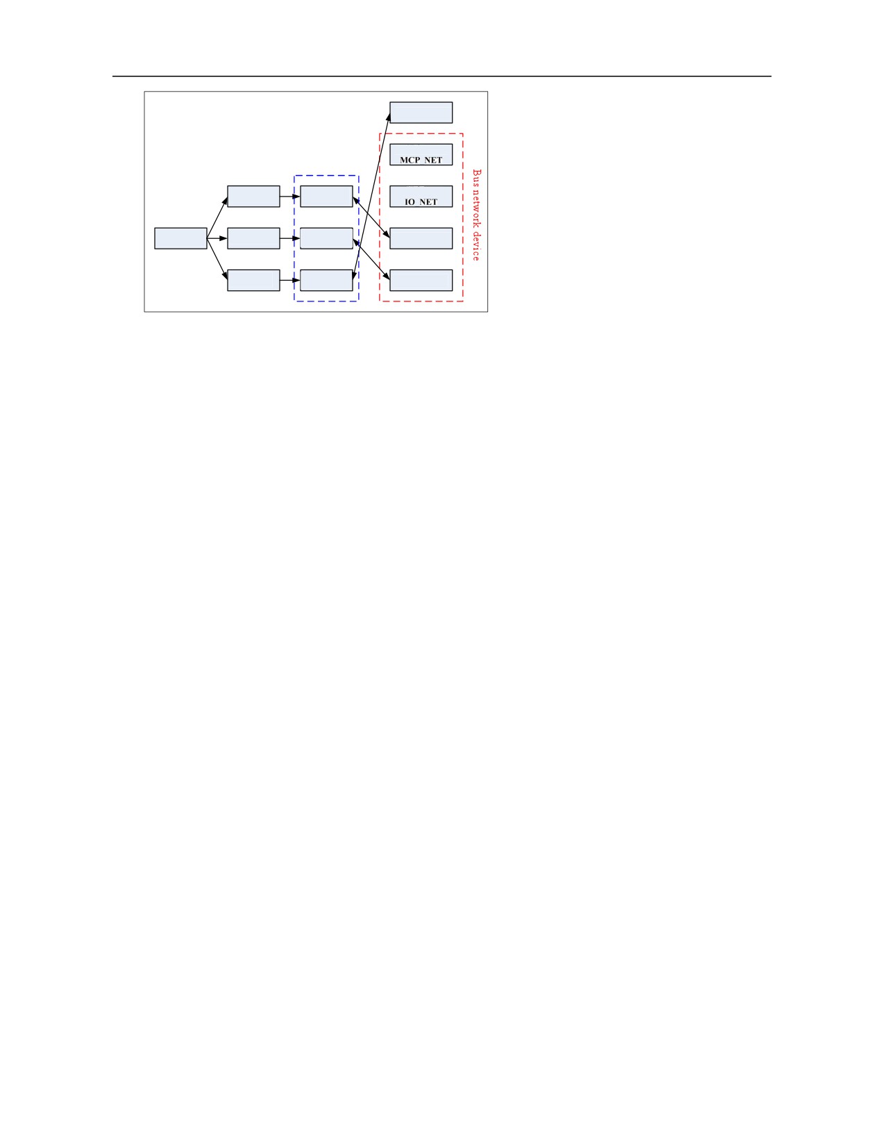
The mapping relationship between
Device #4-SPDL
analog spindle and logical axis
Device #5
Logical axis
Coordinate axis
Device #6
X axis
0
Y axis
Coordinate axis
Device #7-AX
Channel 0
2
Z axis
Coordinate axis
Device #8-AX
5
c. Inverse encoder feedback mark
0: Encoder feedback is directly inputted into the CNC system
1: Inverse encoder feedback is inputted into the CNC system
When spindle feedback rotation speed is displayed oppositely to the actual rotation direction, the parameter
can be set as 1.
d. Spindle DA output type
0: Not distinguish from spindle CW and CCW rotation, output voltage value of 0-10V
1: Distinguish from CW and CCW rotation of spindle, output voltage value of -10- 10V
e. Zero drift adjustment of spindle DA output (mv)
When spindle DA output voltage has zero drift, output voltage can be calibrated through setting this
parameter and actual output voltage of port will substract the set value of the parameter.
Example
When the spindle rotation speed is not output, the voltage value of corresponding DA output port measured
by multimeter is 0.2V (it should be around 0V normally). At this time, to calibrate the output voltage, the
parameter should be set as 200.
f. Feedback position cycle pulse count
The parameter is used to set number of spindle encoder feedback cycle pulses. Generally, pulse count per
revolution of spindle should be filled out.
g. Spindle encoder feedback device number
When the analog spindle gives feedback of encoder pulse count through axis interface board device of bus
IO module, the parameter is used to correlate analog spindle and encoder feedback device. Generally, the
parameter should be set as axis interface board device number in bus IO module.
If the spindle has no encoder feedback, the parameter can be set as -1.
Figure
91
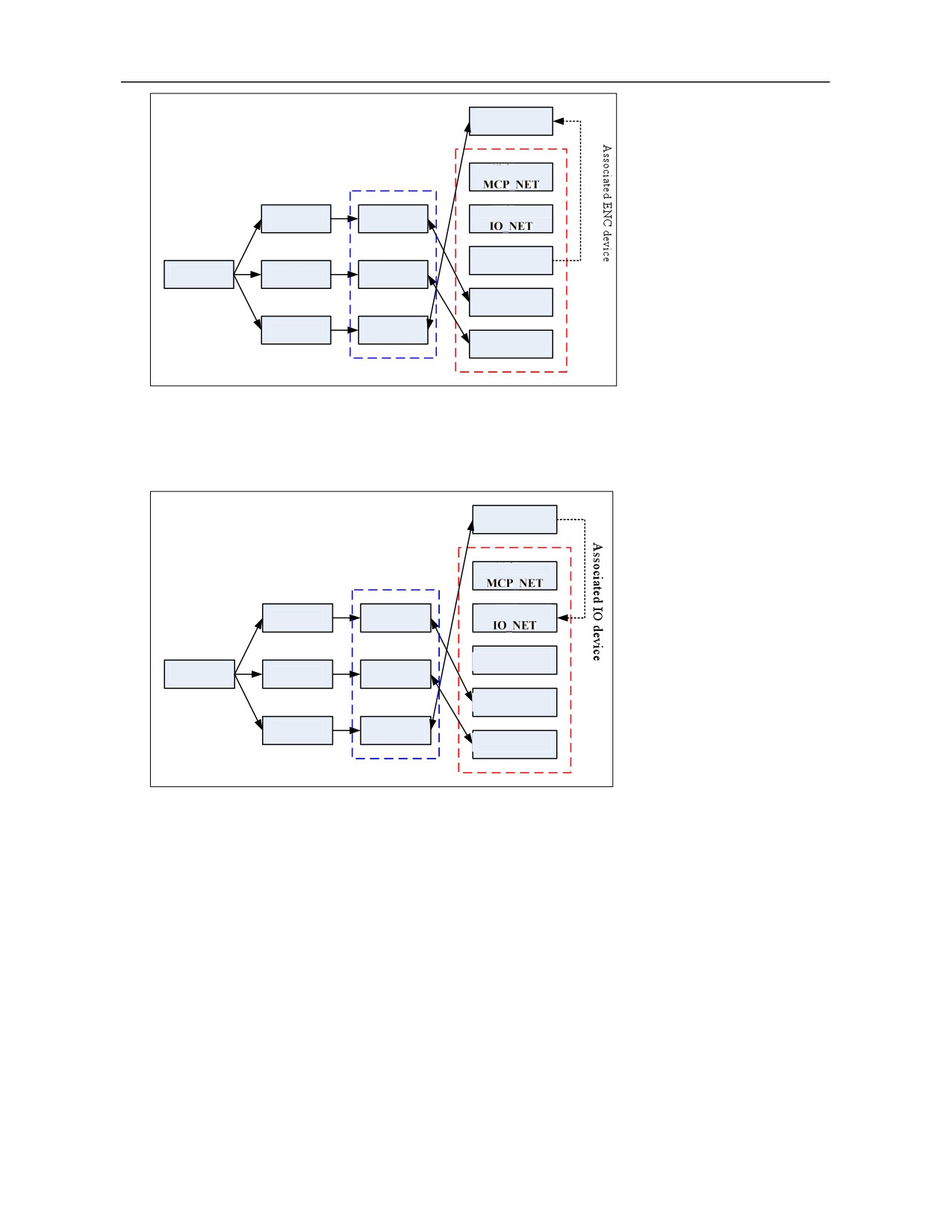
Device
Analog spindle encoder feedback device
#4-SPDL
No.is 7
Logical axis
Device #5-
Coordinate
Device #6-
X axis
axis 0
Device #7-ENC
Coordinate
Channel 0
Z axis
axis 2
Device #8-AX
Coordinate
S axis
axis 5
Device #9-AX
h. Spindle DA output device number
The parameter is used to correlate analog spindle and DA output device. Generally, the parameter should be
set as IO device number with AD/DA function.
Figure
Device
Analog spindle DA output device No.is 6
#4-SPDL
Logical axis
Device #5-
Coordinate
Device #6-
X axis
axis 0
Device #7-ENC
Coordinate
Channel 0
Z axis
axis 2
Device #8-AX
Coordinate
S axis
axis 5
Device #9-AX
i. Spindle encoder feedback interface number
An axis interface board device includes two encoder feedback interfaces. The parameter is used to specify
the serial number of interfaces used by current analog spindle.
0: Use encoder feedback interface A
1: Use encoder feedback interface B
j. Spindle DA output port number
A DA output port occupies 2 groups of Y registers (16-bit output). After IO device number corresponding to
spindle DA output, the parameter is used to locate DA output Y registers, namely offset relative to initial
group number of IO device output point.
Note
Before the parameter is configured, users must fully understand connection of bus IO module and confirm
the position (group number) of spindle DA output Y registers in order to avoid mutual intervention between
DA output and IO output arising from parameter setting error.
92
Example
Suppose DA output device is the bus IO module IO_NET (device #6), initial group number of output point
of this device is 10. Where, Y10-Y13 are used for IO output and Y14-Y19 are used for DA output. Thus,
analog spindle DA output can be configured as follows:
Parm500017 “Spindle DA output device number” is set as 6.
When the specified spindle DA output port number is 2, the position of DA output Y register is Y14-Y15;
When the specified spindle DA output port number is 3, the position of DA output Y register is Y16-Y17;
When the specified spindle DA output port number is 4, the position of DA output Y register is Y18-Y19.
7. PLC Commissioning
7.1 HNC-8 PLC Structure
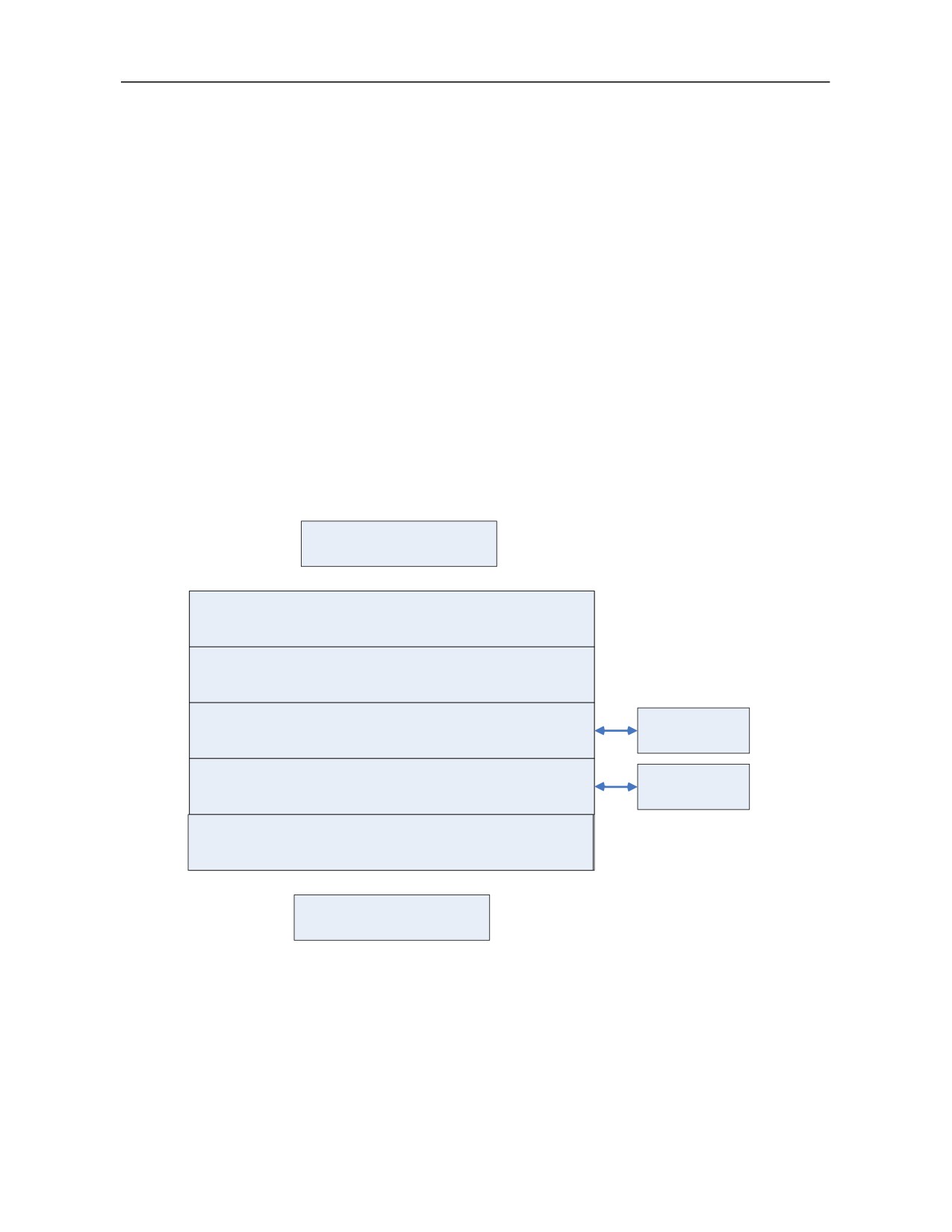
HNC-8 ladder diagram PLC adopts cyclic scanning mode. In the beginning of program execution, PLC
will be initialized once when it is powered on or reloaded. Then, all inputted states is sent to the input map
register and user programs PLC1 and PLC2 are called in sequence. When a scanning cycle is completed, all
results will be transmitted to the output map register to control actual output of PLC, and so on.
Start scanning
Initialization (finish with iend, execute once only
during power-on and PLC reloading)
input map register
PLC1 (execute every scanning period, finish with 1end)
Subprogram
PLC2 (execute every scanning period, finish with 2end)
Subprogram
Output map register
Finish scanning
7.2 Working Principle of PLC Interface Signal
PLC interface signal is responsible for information exchange between PLC and NC.
93
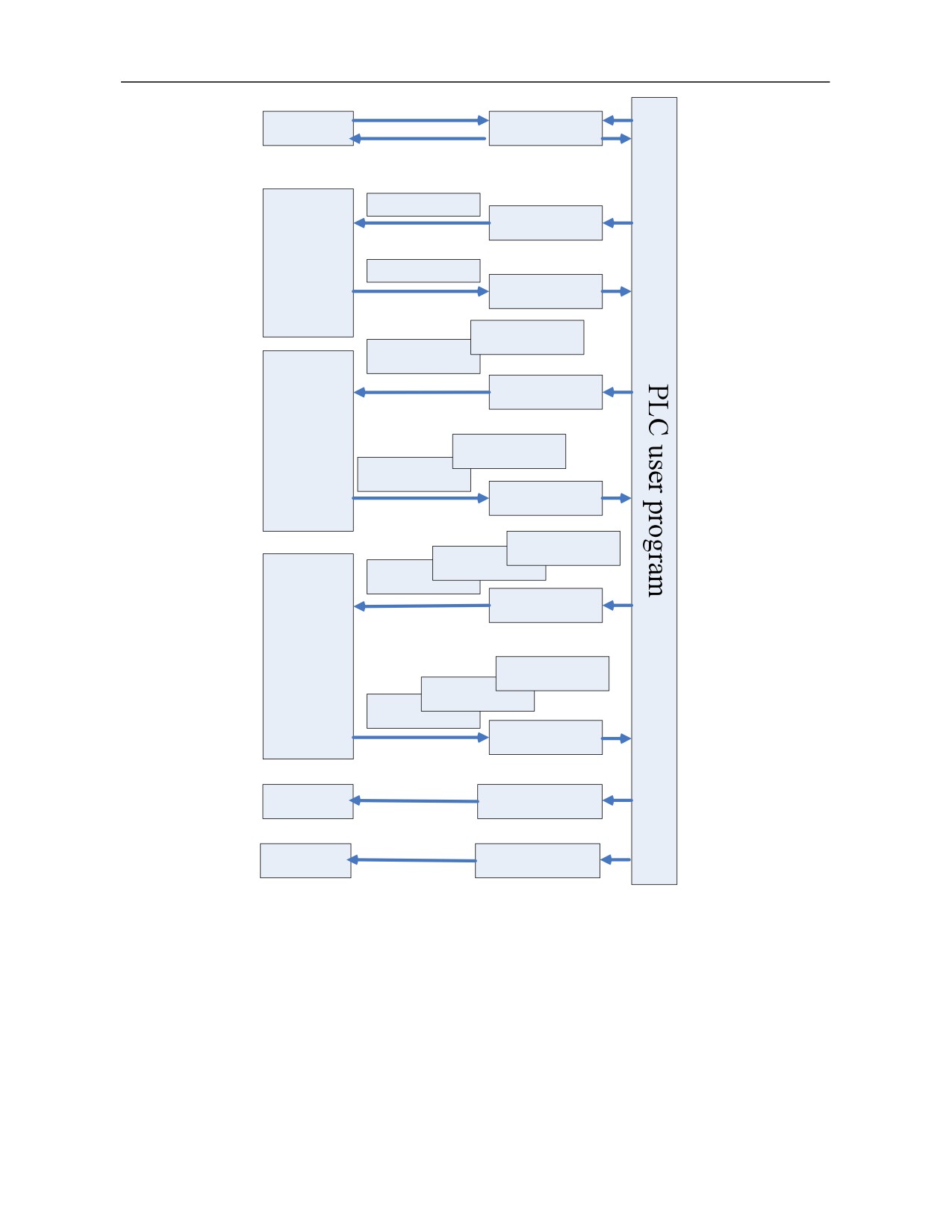
User data
B0~B1721
G2960~G3099
To NC
NC
F2960~F3099
From NC
G2640~G2720...
G2560~G2639
To NC
Channel
F2640~F2720...
F2560~F2639
From NC
G160~G239…
G80~G159
G0~G79
To NC
Axis/
spindle/drive
F160~F239…
F80~F159
F0~F79
From NC
PLC alarm
G3010~G3041
PLC prompt
G3056~G3087
F register is a status flag register used to input CNC input signal to PLC control module from CNC.
G register is a control flag register used to output CNC output signal to CNC from PLC control
module and signals processed by CNC.
B register is a data register (its value can remain at the state before power-off). The data register can
also be used as PLC parameter and users can define usage of every parameter.
94

7.3 PLC Specification
Specification
HNC8
Programming language
Ladder,STL
The first-level program execution cycle
1ms
Program capacity
Ladder diagram
5000 lines
Statement list
10000 lines
Symbol name
1000 Pcs.
Command
Basic command, function command
Single-byte internal relay (R)
2048 bytes (R0-R2047)
Double-byte internal register (W)
512 bytes (W0-W255)
Four-byte internal relay (D)
1024 bytes (D0-D255)
Timer (T)
512(T0--T511)
Counter (C)
512
(C0--C511)
Subprogram (S)
253(S0-S252)
Mark number
(L)
10000(L0-L9999)
User-defined parameter (P)
700 (P0-P699)
Single-byte internal register (I)
128 bytes (I0-I127)
Single-byte internal register (Q)
128 bytes (Q0-Q127)
Hold storage area
Four-byte register (B)
6888 bytes (B0-B1721)
Hold relay (K)
128 bytes (K0-K15)
I/O module (X)
X0--X511
(Y)
Y0--Y511
7.4 Ladder Diagram Operation on CNC Controller
To realize functions of ladder diagram on the CNC system end, permission of machine tool manufacturer or
above should be inputted.
Press "Ladder " in the diagnosis operation interface to enter the ladder diagram operation interface.
95
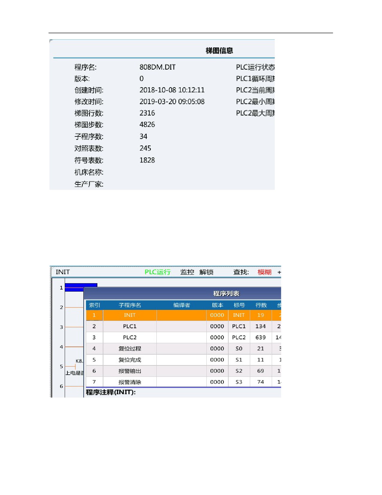
7.4.1 Ladder Diagram Monitoring
Select function key "Ladder Monitor" to enter the ladder diagram monitoring interface. The ladder diagram
monitoring interface includes 7 function keys: program list, find, disable, allow, restore, lock list and cross
reference.
1) Program list
Function: Display PLC program block.
96
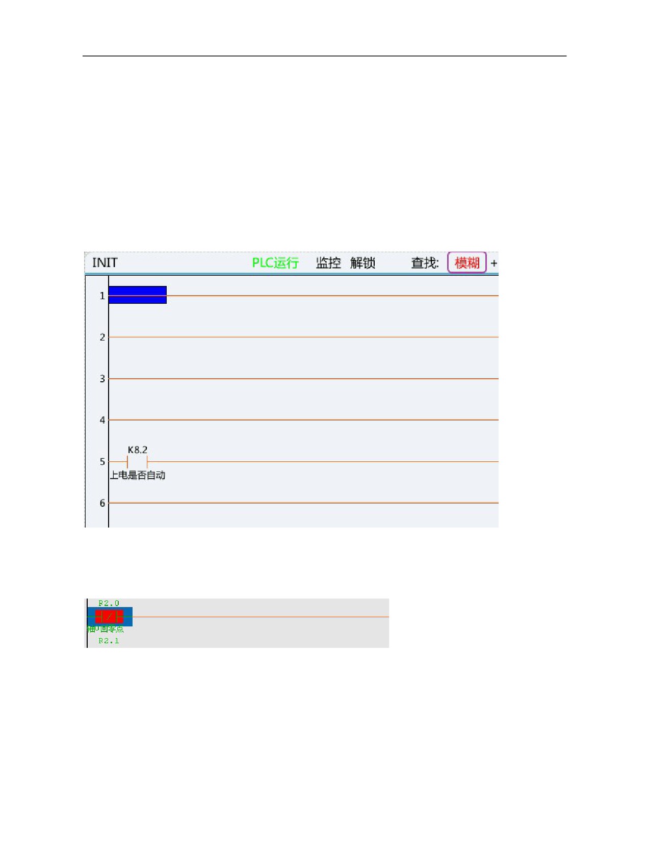
2) Find
Search according to type:
1. Address: Search according to address
2. Command: Search according to function instruction
3. Output: Search according to output result
4. Line number: Search according to line number of PLC
Continue searching:
1. Find next: Continue searching downwards
2. Find previous: Continue searching upwards
Search range:
1、 Search mode: Fuzzy search mode, accurate search mode
2、 Search range: Local search, global search
3) Disable
Function key "Disable". Move the cursor to an element and press this key to shield the element. As shown
below, move the cursor to an element, press this key and the element turns red. It means that the element is
shielded and cannot be outputted.
Note: The inhibited conditions here are valid for current line only. As shown above, after R2.0 normally-closed
is disabled, it is turned off for this line only.
4) Allow
Function key "Allow". Move the cursor to an element and press Allow to activate the element. As shown below,
move the cursor to an element, press Allow and the element turns green. It means that the element is activated.
As shown in the figure, X3.0 is the normally open. Move the cursor to X3.0, press "Allow", the element turns
green.
97
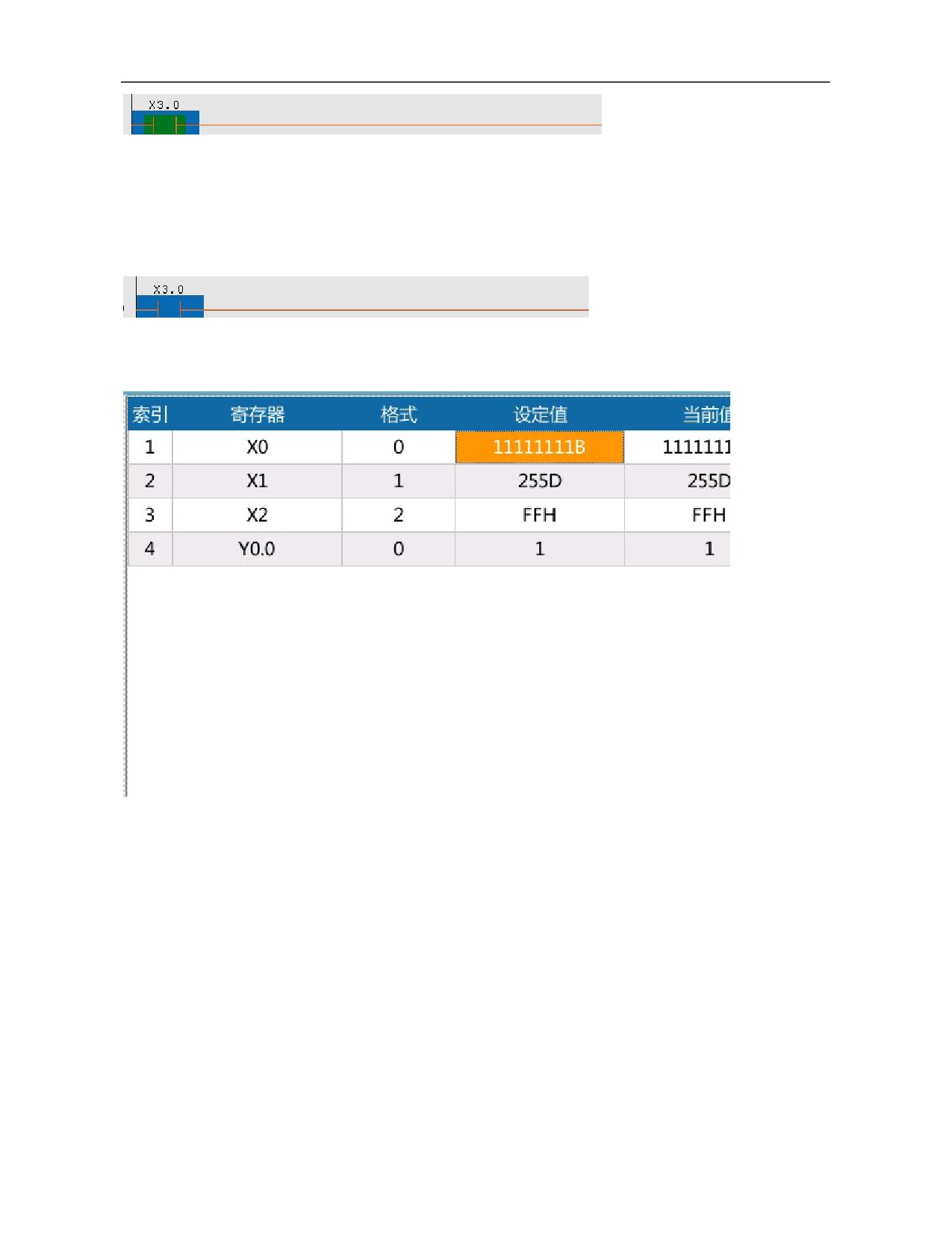
Note: The inhibited conditions here are valid for current line only. As shown above, after X3.0 normally open is
allowed, it is turned on for this line only.
5) Restore
Function key "Restore". Move the cursor to an element, press Restore to cancel operation of the aforesaid
shielded or activated element. Press Restore after the Disable and red color of the element disappears. It means
that functions of the element are restored, as shown below.
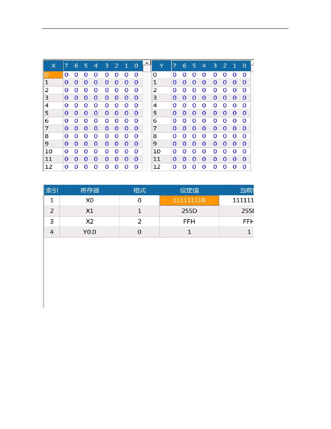
6) Lock list
Lock list (register lock list) is mainly used to write specified data of register and lock register value. Presently,
only write, lock and unlock of X/Y register are supported.
1.
Add: Add index
2.
Delete: Delete index (current index item is at unlock state)
3.
Write: It is used for a write of register (bit). If other logics in PLC also modify the current register (bit)
where data is written, the written value may be eliminated by other bits.
4.
Lock: Assign the set value to register forcibly. While adding register (bit) in the lock list interface, the
system sets mutual exclusion rules for registers. That is, only register value or register bit can be inputted when
index number of registers of the same type is the same. e.g.: After X0 is inputted, subsequent data including the
register bit information such as X0.0 and X0.7 cannot be inputted, because they are exclusive of the previously
inputted X0. Likewise, after Y0.0 register bit is inputted, the newly added data must be register bit data between
Y0.1 and Y0.7 and Y0 register value cannot be inputted.
5.
Unlock: Release lock state.
6.
Format:
Format value range:
0: Binary
1: Decimal
98
2: Hexadecimal
e.g.:
Initial state of system input and output:
Lock and assign X0, X1 and X2 groups and Y0.0:
The locked input and output state is shown below:
99
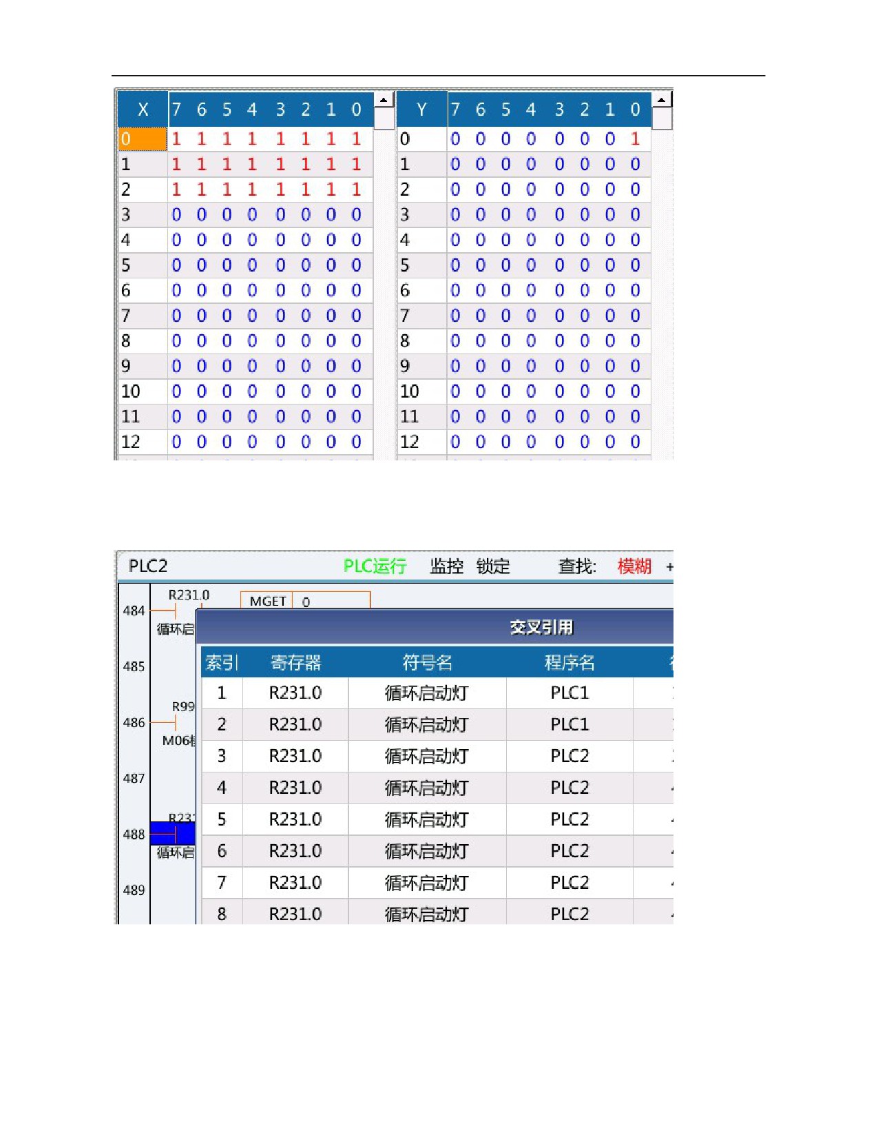
7) Cross reference
Similar to finding register, the cross reference is mainly used to search reference relationship of register (bit)
information in a global range. How to use: Move the cursor to the register to be searched, press this key and the
block diagram of cross reference will pop up automatically.
7.4.2 Ladder Editing
Select "Ladder edit" to enter the ladder diagram edit interface. The ladder diagram edit interface includes 16
function keys, including program list, straight line, normally open, normally closed, logical output, inverse
output, vertical line, delete vertical line, find, delete element, function module, edit network, list edit, double
100
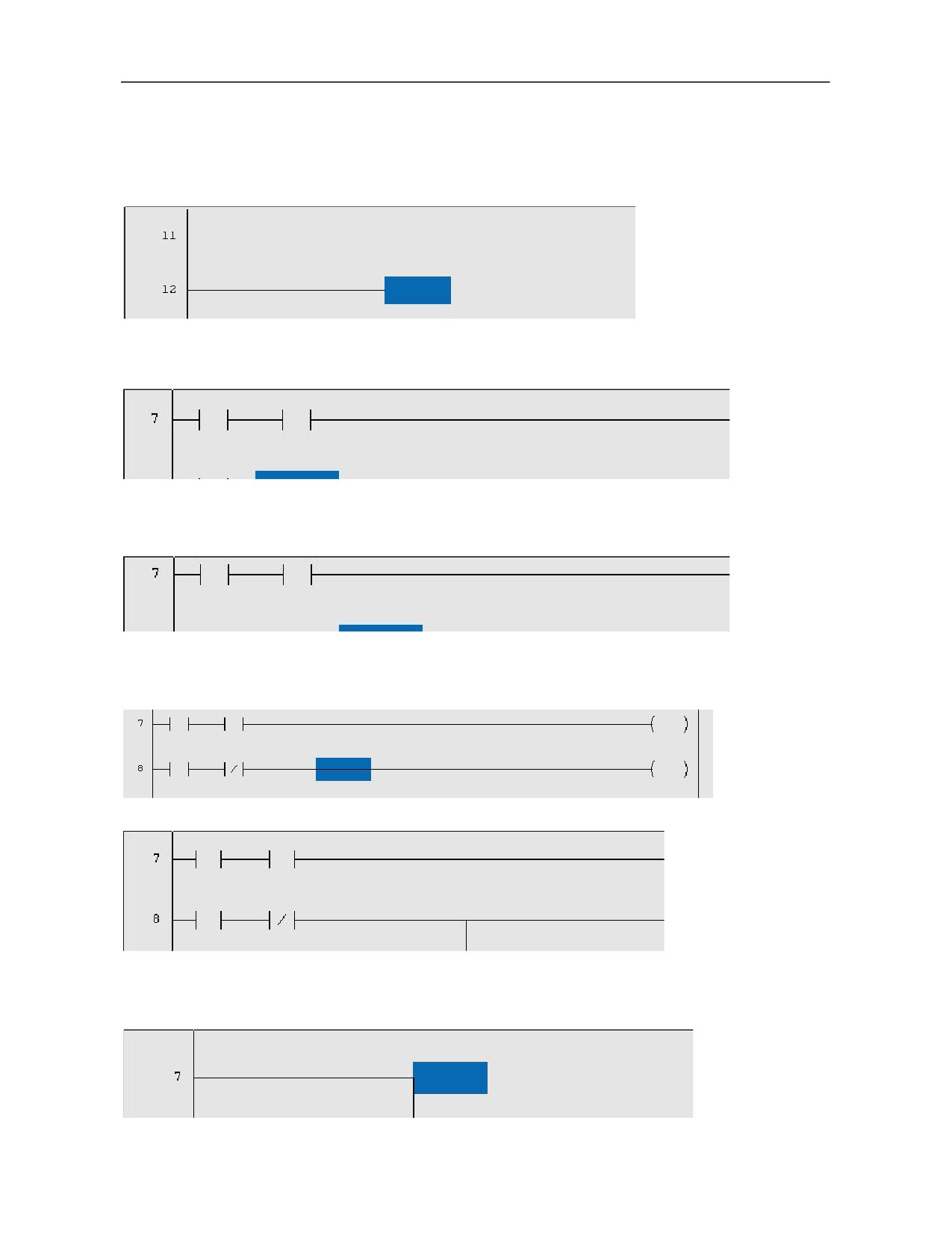
coil, update modification and abandon modification.
1) Program list
Function: Display PLC program block. Consistent with program list function in ladder diagram monitoring.
2) Straight line
Press this key to insert a straight line in the ladder diagram.
3) Normally open
Move the cursor to the position where normally open needs to be inserted and press this key to insert normally
open in the specified position in the ladder diagram.
4) Normally closed
Move the cursor to the position where normally closed needs to be inserted and press this key to insert normally
closed in the specified position in the ladder diagram.
5) Logical output
Move the cursor to the position where logical output needs to be inserted and press this key to insert logical
output in the specified position of the ladder diagram.
6) Inverse output
Move the cursor to the position where inverse output needs to be inserted and press this key to insert the inverse
output in the specified position in the ladder diagram.
7) Vertical line
Press this key to insert a vertical line after the cursor.
101
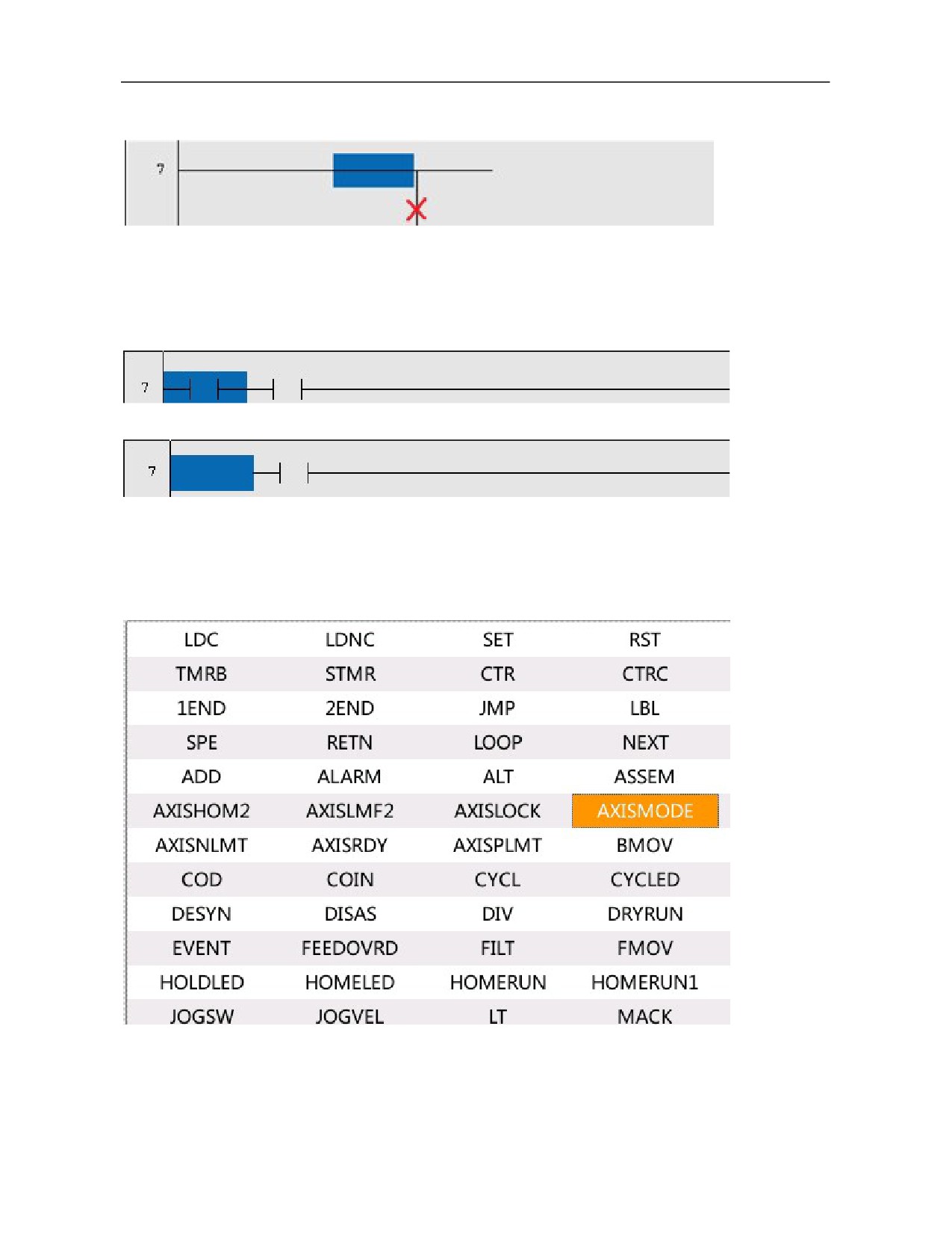
8) Delete vertical line
Press this key to delete the vertical line after the cursor.
9) Find
Consistent with the find function in ladder diagram monitoring.
10) Delete element
Move the cursor to the element to be deleted and press this key to delete the element in the ladder diagram.
Before deletion:
After deletion:
11) Function module
Function module includes all function ommand lists and corresponding help files of the CNC system.
e.g.:
When the cursor moves to the position of axis working mode, press Help and the system will display the help
instructions of corresponding function module.
102
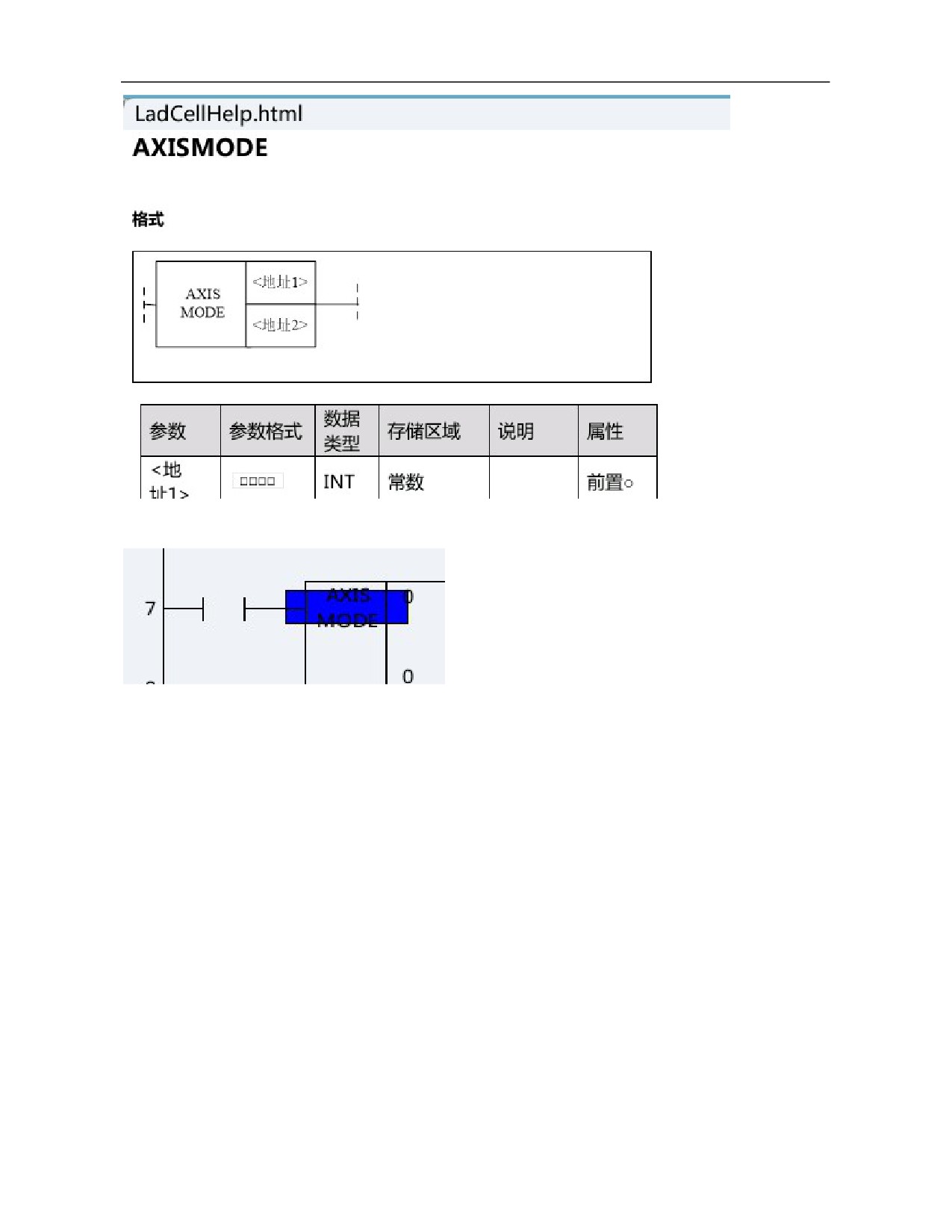
If it is unnecessary to view help file, Press Enter on the function module of corresponding cursor in the function
instruction list and the system will insert the function module into current PLC.
12) Edit network
Edit network includes insert line, delete line, insert column, select network, copy network, cut network, paste
network and delete network.
a. Insert line
Move the cursor to the next line of the line to be inserted and press this key to insert a line, as shown below. It
should be noted that the inserted line is often above the line where the cursor is inserted.
Before inserting line:
103
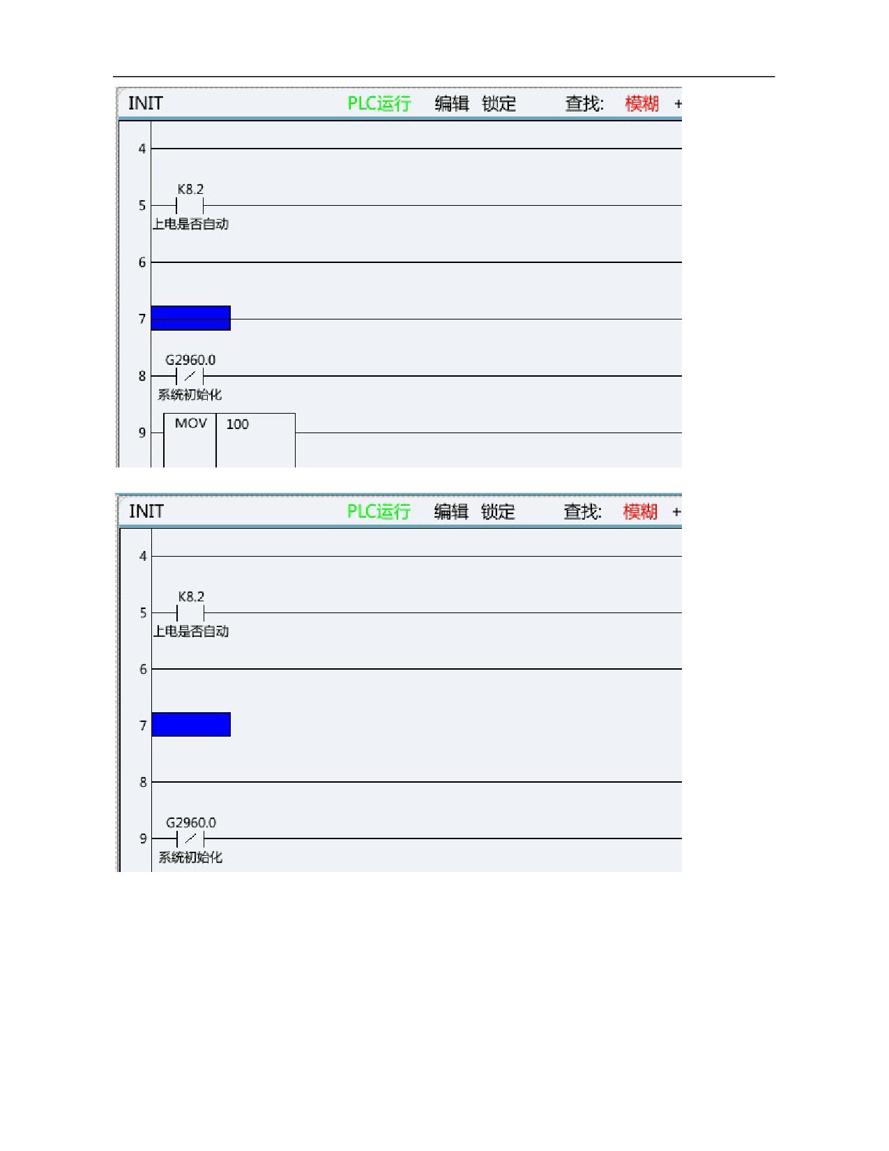
After inserting line:
b. Delete line
Move the cursor to the position where the line to be deleted and press this key to delete this line of PLC ladder
diagram.
Before deletion:
104
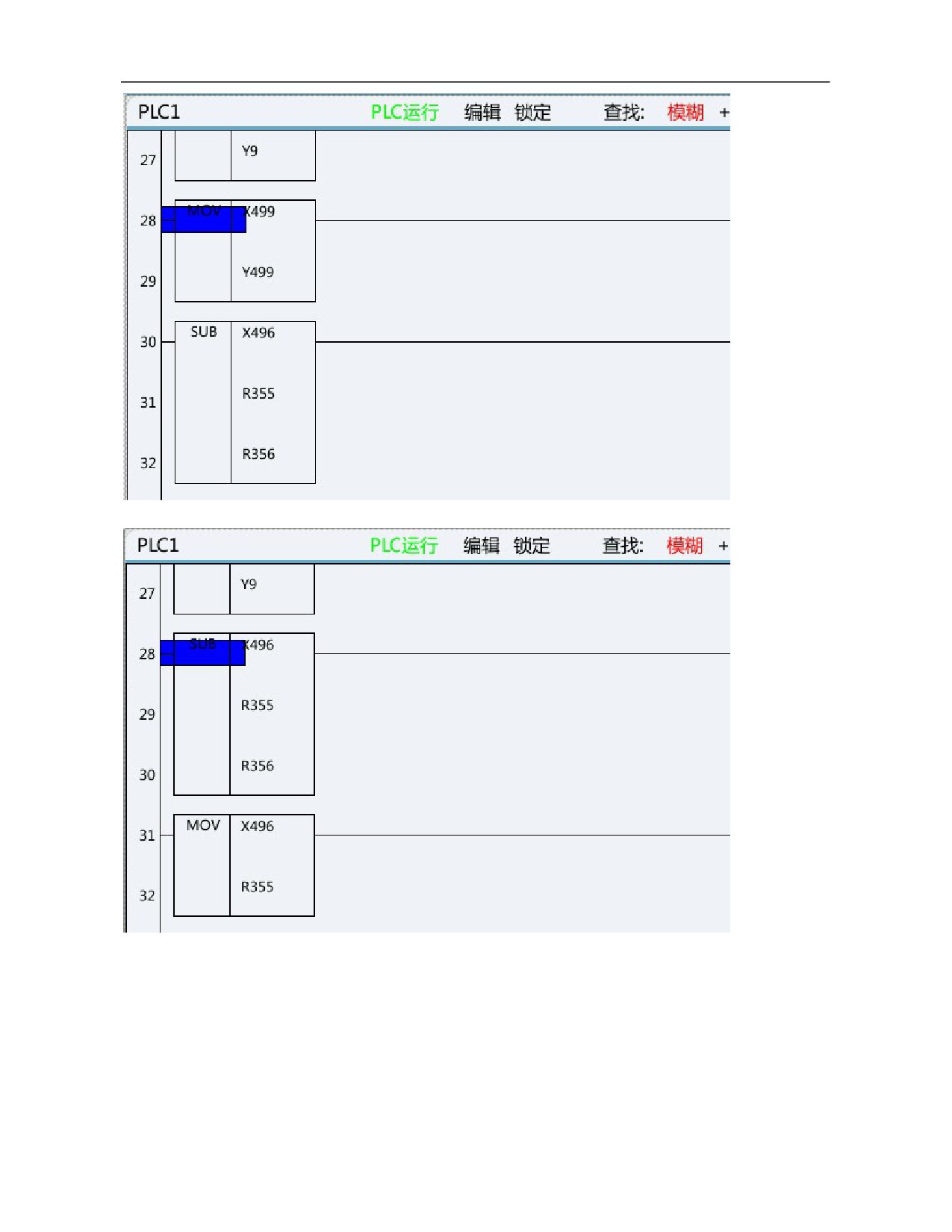
After deletion:
c. Insert column
Move the cursor to the next position of the column to be inserted and press this key to insert a column.
Before inserting column:
105
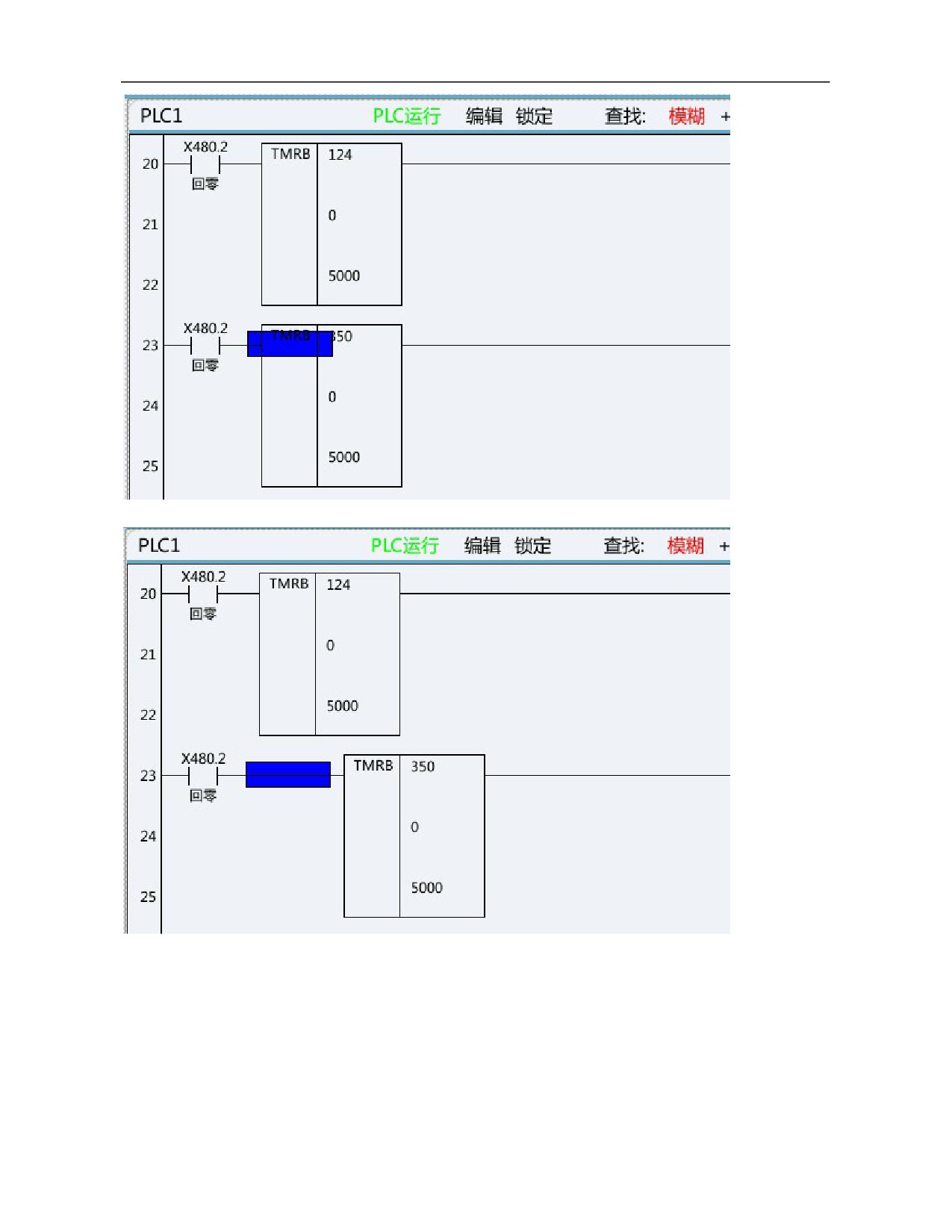
After inserting column:
d. Select network
Move the cursor to the line to be selected, press this key, and the selected line turns blue. Press this key again to
select the next line of current line. Select the selected network for subsequent operations such as copy network,
cut network and delete network.
106
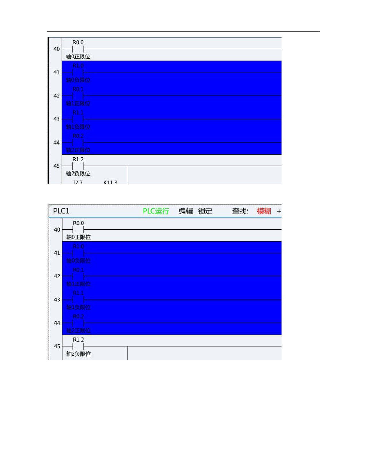
e. Copy network
After a network is selected, press this key to copy the network.
f. Cut network
After a network is selected, press this key to realize movement of network.
107
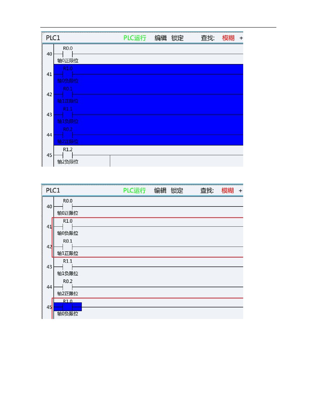
g. Paste network
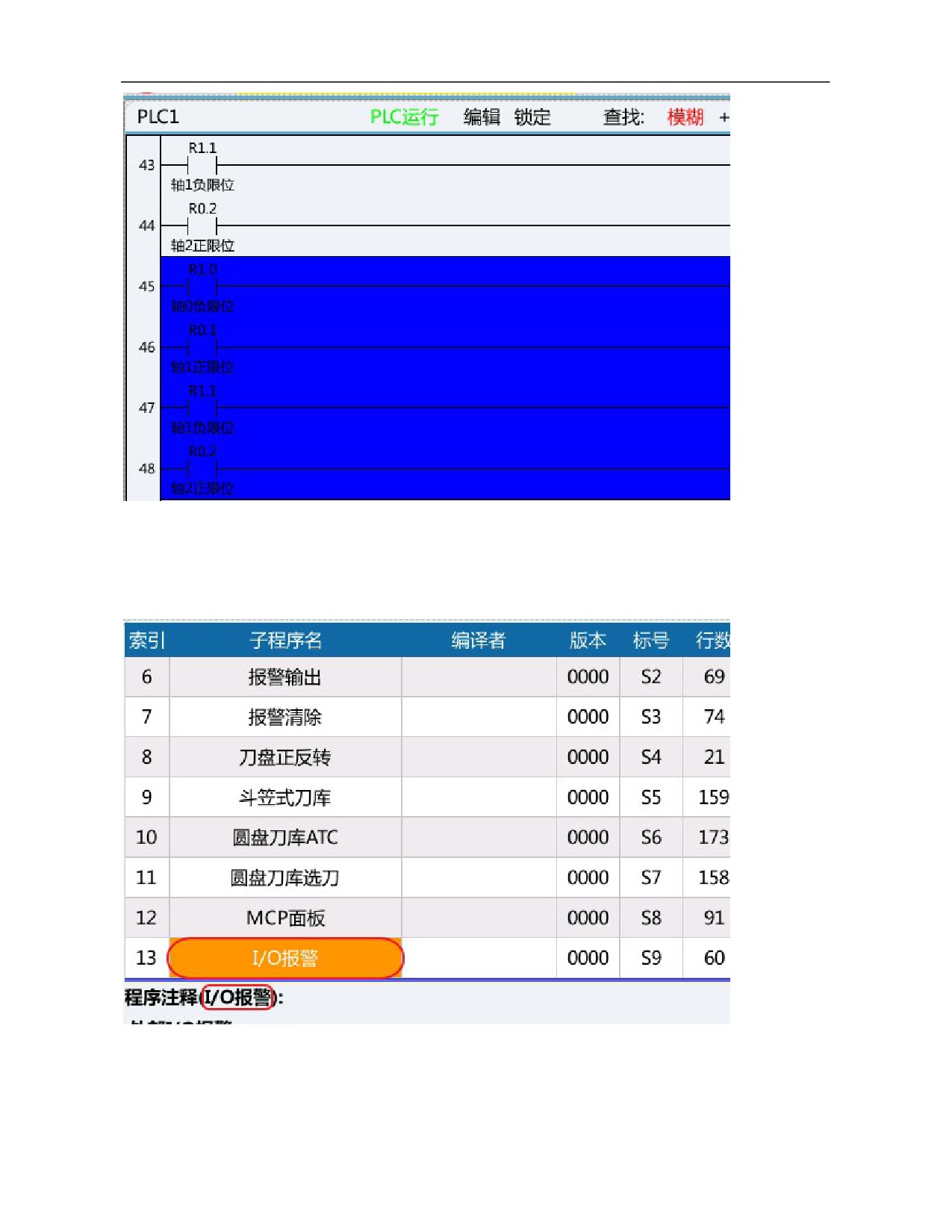
After a network is copied or cut, move to the target position and press this key to paste the network.
h. Delete network
After a network is selected, press this key to delete the network.
108
13) List editing
List edit includes modify list, modify notes, add module, delete module, update modification and abandon
modification.
a. Modify list
This function can realize modification of program name.
b. Modify annotation
This function can realize detailed comments of current subprogram.
109
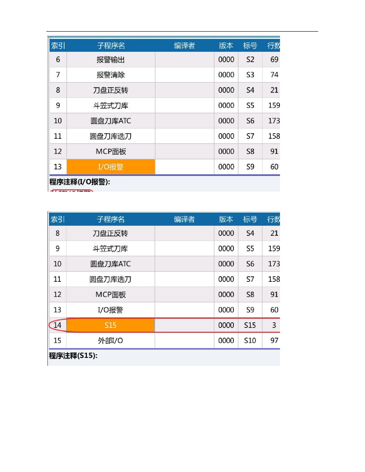
c. Add module
This function can add subprogram to current PLC.
d. Delete module
This function can delete current subprogram.
110
e. Update modification
This function can update and save the modified PLC file.
f. Abandon modification
This function can abandon saving the current modified file.
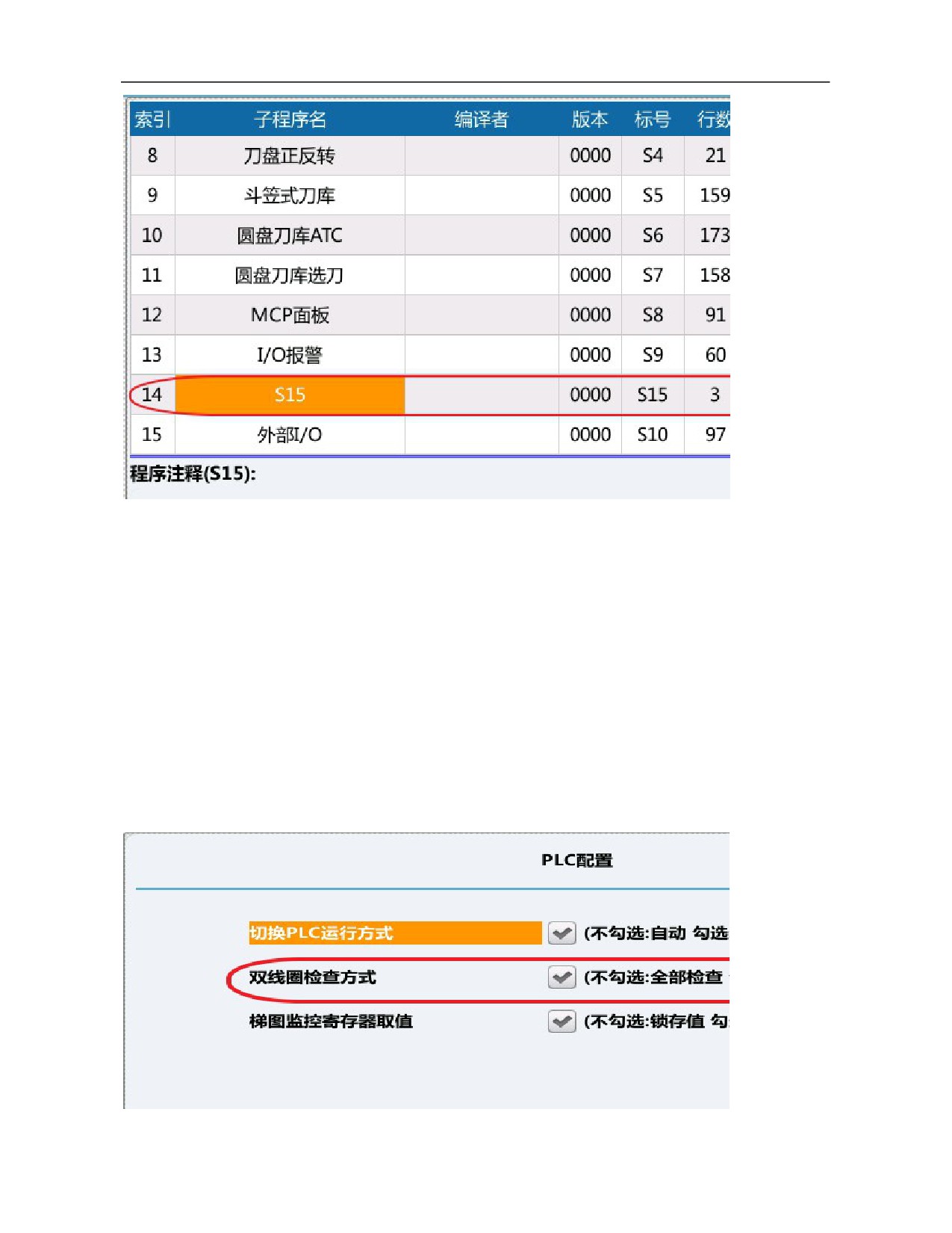
14) Double coil
Double coil function is used to check problems of double coil output in PLC.
Note: The parameter is used to inspect all coils or coils of current line according to double coil inspection mode
in ladder diagram option function. While inspecting coils of current line, the cursor should move to the line
where it is necessary to inspect whether there is double coil output. While inspecting all coils, the cursor can be
in any position.
e.g.:
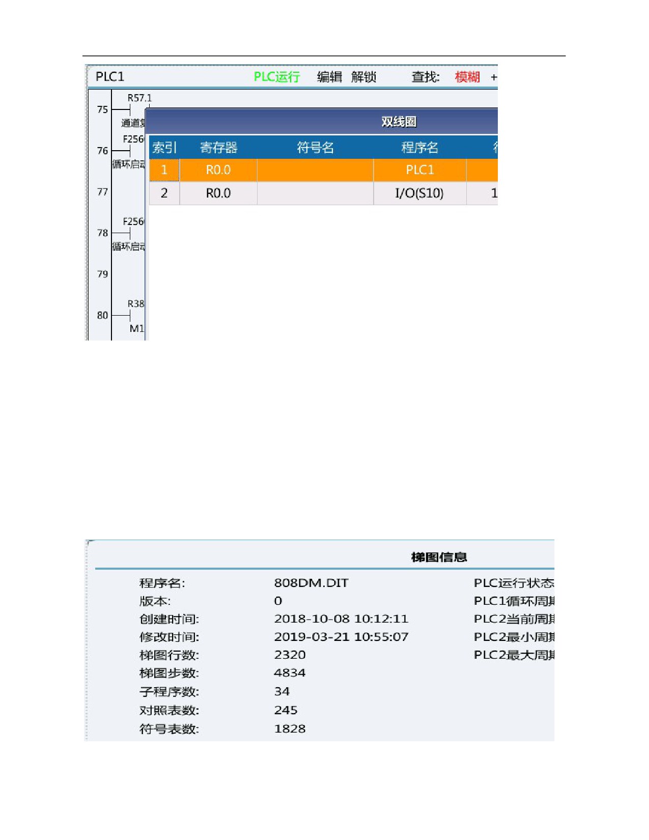
Line 76 and line 1631 in the original PLC output R0.0 simultaneously.
111
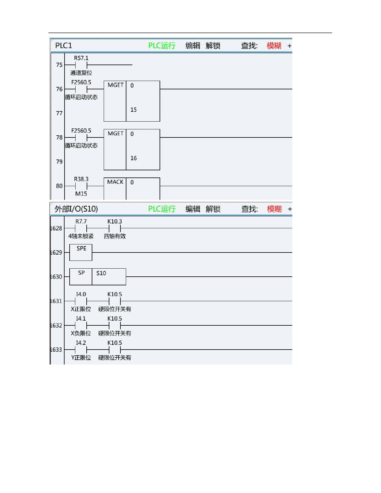
Move the cursor to line 76 or line 1631, press Double Coil, then the system will display R0.0 register as double
coil output automatically.
112
15) Update modification
This function can update and save the modified PLC file.
16) Abandon modification
This function can abandon saving the currently modified file.
7.4.3 Ladder Diagram Information
This function includes ladder diagram title, symbol table, IO comparison table, K parameter, timer, counter,
alarm setting, run stop and online commissioning.
1) Ladder diagram title
Ladder diagram title stores some descriptive information of current PLC file, including project version, project
name, writer, comments, machine tool manufacturer information, manufacturer information and PLC running
status, etc.
2) Symbol table
Symbol table is mainly used to store symbol names and comments of register (bit) information.
113
3) IO comparison table
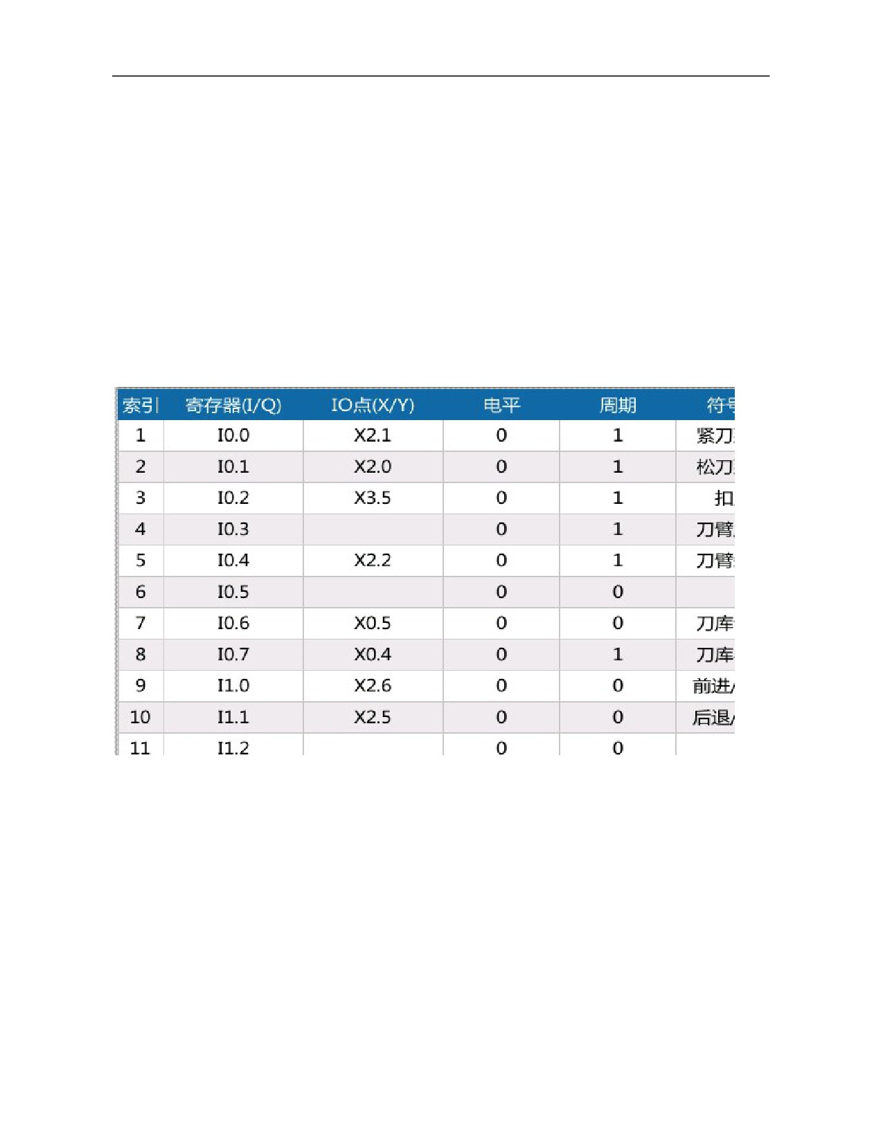
IO comparison table is a new function of HNC-8 new version of ladder diagram which is mainly used to
standardize ladder diagram PLC writing. That is, in the standard ladder diagram, input and output of standard
functions that offered to users are replaced by I and Q, in which I is mapped to X and Q is mapped to Y. Users
can correspond X and Y points to I and Q according to the electrical schematic diagram of machine tool. In this
case, it is unnecessary to modify element parameters of ladder diagram PLC but to update data of corresponding
IO comparison table in order to ensure normal operation of PLC. As a result, developer and commissioning
personnel's work is greatly simplified and work efficiency improves.
The ladder diagram software specifies the range of IQ registers according to usage scenario. The number of IQ
comparison tables (users) is 80 and the range is indexes 0-79. The number of IQ comparison tables (system
panels) is 48 and the range is indexes 80-127.
In the ladder diagram software interface, IQ register is edited in 2 interfaces (user IO comparison table and
panel IO comparison table). The index values of IQ registers which can be edited in different interfaces are
different.
114
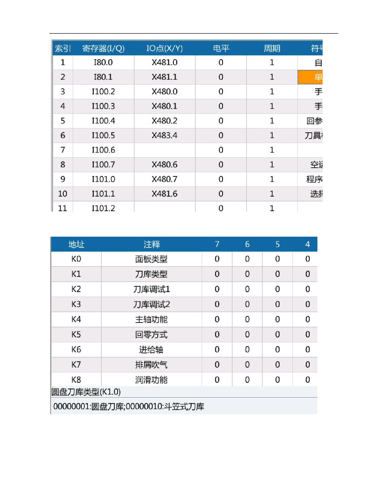
4) K parameter
Used to set K parameter value.
5) Timer
Used to view state of timer used in the system.
6) Counter
Used to view state of counter used in the system.
7) Alarm setup
115
Used to view and set alarm and prompt messages of system PLC.
8) Stop operation
Run stop function is used to stop running of current PLC.
Note: After running is stopped, press Run stop again to rerun PLC.
9) Online commissioning
Online commissioning function enables the user to monitor running status of NC remotely and commission
specific points and program state. The communication with HNCLadder software can be realized.
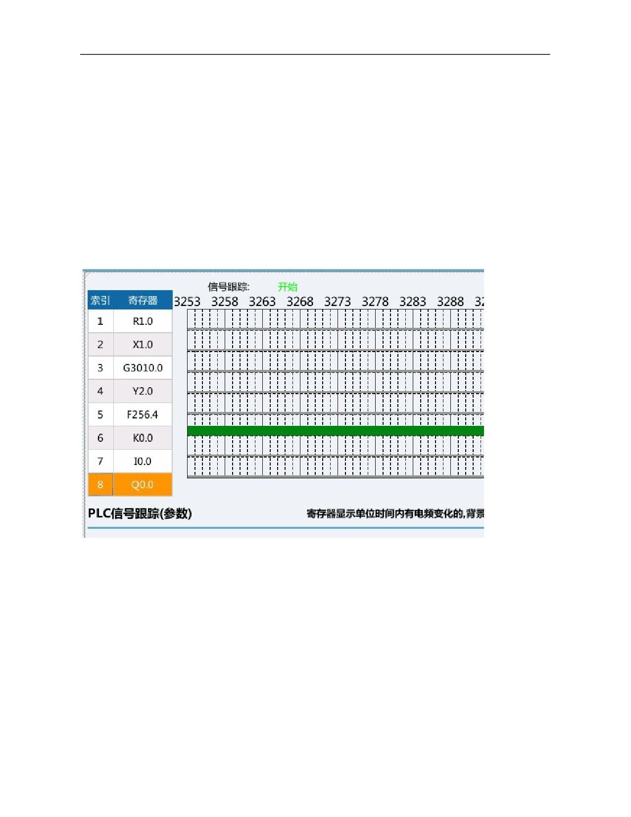
6.4.4 Signal Tracking
Signal tracking is mainly used to display data of real-time sequence chart of register points X, Y, F, G, R, I, Q
and K.
8 groups of data can be acquired simultaneously. If the default sampling period is 1ms, the maximum sampling
time is 60s.
7.4.5 Ladder Diagram Option
1) Double coil inspection
Not ticked: Inspect all
Ticked: Inspect current line of coils
Note: This function should be used cooperatively with double coil function in ladder diagram edit.
2) Ladder diagram monitoring register value
Not ticked: Latched value
Ticked: Current value
This function is mainly used to eliminate conflicts incurred during inspection of values in PLC assignment
statement. This function is mainly used to check the investigation work when the assignment conflicts in the plc
assignment statement
Current value is ticked by default and values of registers displayed in the ladder diagram monitoring screen are
116
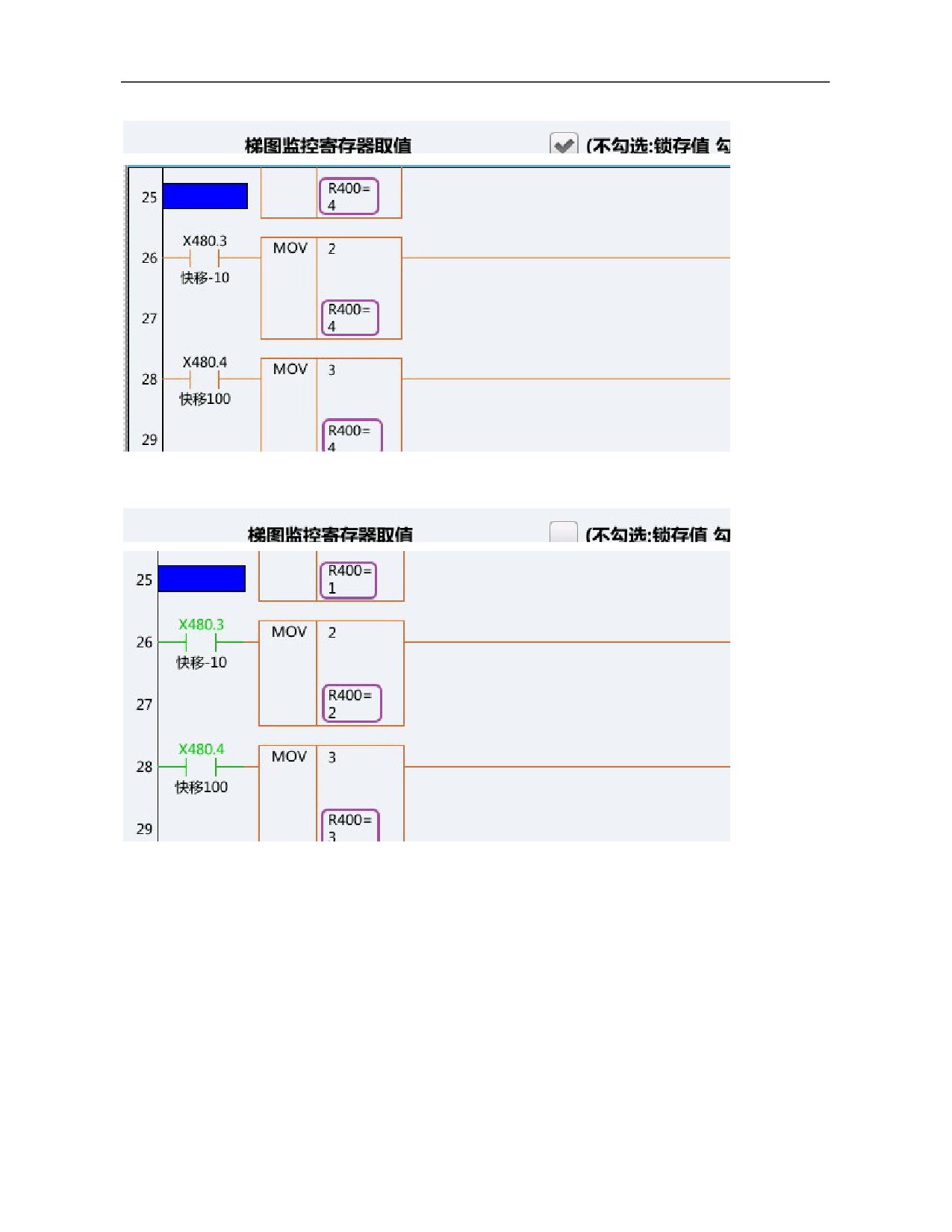
consistent.
When latched value is displayed, values of registers displayed in the ladder diagram monitoring screen are
displayed independently for each module.
8. Design Example of CNC Milling System
With the section 1.1 as an example, corresponding bus should be connected as per section 2.1.
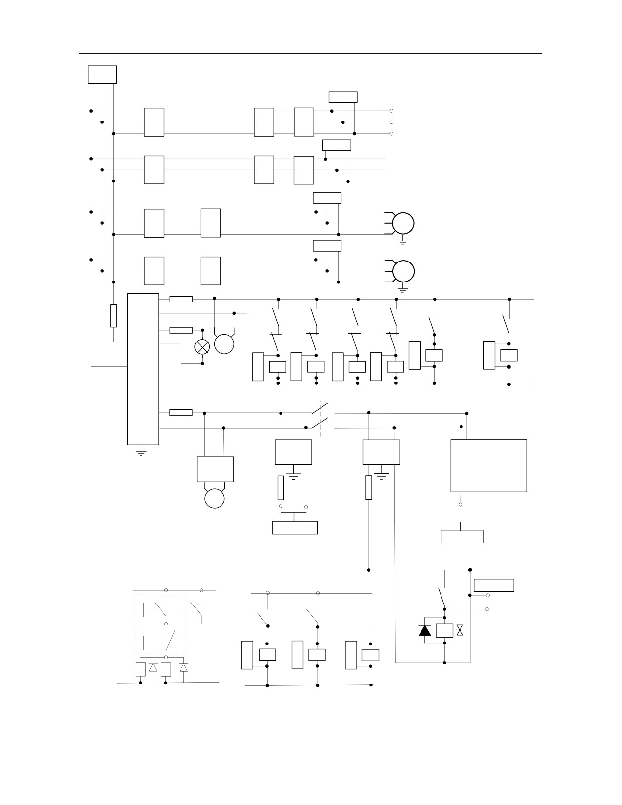
8.1 Electrical Schematic Diagram
In the design, AC24V power supply of floodlight, DC24V power supply used by magnetic valve of large
operating current and DC24V power supply used by output switch value (such as relay and servo control signal,
etc.) are independent and separated by a low pass filter.
Anti-interference magnet ring and high-voltage ceramic capacitor at the main power supply inlet and
117
transformer input end are not indicated in the figure. As shown below.
In the figure below, QF0-QF4 are three-phase air switches; QF5-QF11 are single-phase air switches; KM1-KM4
are three-phase AC contactors; RC0-RC3 are three-phase RC absorbers (arc extinguishers); RC4-RC12 are
single-phase RC absorbers (arc extinguishers); KA0-KA11 are DC 24V relays; VX is freewheel diode; YVZ is
magnetic valve and Z axis motor brake.
118
QF0
63A
RC0
L11
QF1
KM9
L12
Feed axis drive power
25A
25A
L13
Three-phase isolation transformer
RC1
380V 3P/220V 3P
L21
QF2
KM10
L22
Spindle drive power
20A
20A
L23
Spindle drive
RC2
resistor
QF3
KM1
M
Magazine power
9A
9A
RC3
QF4
KM2
M
Cooling motor
9A
9A
QF8
110VA
QF5
3A
AC110V
250W
3A
KA8
KA9
KA6
KA7
KA3
KA4
QF7
6A
AC24V
RC7
RC9
100W
M
KM5
KM6
KM7
KM8
AC380V
KM3
KM2
750W
Electric
RC3
KM6
RC4
KM5
RC5
KM8
RC6
KM7
Floodlight
cabinet fan
110VB
Positive
Negative
Lubrication
Positive
Negative
Cooling motor
rota tion of
rota tion of
rota tion of
rotation of
motor
magazine tool magazine tool
cutter
cutter
QF6
3A
AC220V
KM11
300W
Switching power
switching power
J1
AC220V/
AC220V/
50W
DC24V
100W
DC24V
Control transformer
UPS power
KM3
Automatic
QF10
QF9
lubrication station
3A
6A
M
24V2
100
24V1
24V UPS
Power output
To:
Relay
To:
CNC device
24V2
110VA
To Z axis servo
KA0
101
-SB2
-KA11
KA10
2100
KM11
VX
YVX
NC ON/OFF
RC10
RC11
RC12
-SB1
button
Z axis brake
100
110VB
-KA11
-KA10
KM11
KM9
KM10
NC ON/OFF control
Electrical schematic diagram of typical CNC system-power supply diagram
119
8.2
Commissioning Procedure
8.2.1 First Power-on and Commissioning Procedure of Machine Tool
Note: Do not turn on the emergency stop button of the system. If conditions permit, it's best not to connect the
power line of traverse axis servo motor and power line of spindle servo motor.
Parameters to be set or checked when the machine tool is powered on for the first time:
Machine user parameters:
Parm010000, maximum number of channels: 1
Parm010001, cutting type of channel 0: 0 (milling system)
Parm010009, selection mark of channel 0: 1
Parm010017, display axis mark [1] of channel 0: 0x27
Parm010033, load current display axis customization of channel 0: 0,1,2,5
Channel parameters (channel 0):
Parm040001, X coordinate axis number: 0
Parm040002, Y coordinate axis number: 1
Parm040003, Z coordinate axis number: 2
Parm040010, axis number of spindle 0: 5
Parm040028, display axis number of spindle: 5
Coordinate axis parameters:
Logical axis 0:
Parm100000, display axis name: X
Parm100001, axis type: 1 (linear axis)
Logical axis 1:
Parm101000, display axis name: Y
Parm101001, axis type: 1 (linear axis)
Logical axis 2:
Parm102000, display axis name: Z
Parm102001, axis type: 1 (linear axis)
Logical axis 5:
Parm105000, display axis name: C
Parm105001, axis type: 10 (spindle)
Device interface parameters:
Device 4:
Parm504000, device name: SP
Parm504011, logical axis number: -1
Device 5:
Parm505000, device name: MCP_NET
120
Parm505010, MCP type: 7
Parm505012, initial group number of input point: 480
Parm505013, number of input point groups: 10
Parm505014, initial group number of output point: 480
Parm505015, number of output point groups: 10
Device 6:
Parm506000, device name: MCP_NET
Parm506010, MCP type: 7
Parm506012, initial group number of input point: 490
Parm506013, number of input point groups:10
Parm506014, initial group number of output point: 490
Parm506015, number of output point groups: 10
Device 7:
Parm507000, device name: AX
Parm507010, working mode: 3 (speed mode)
Parm507011, logical axis number: 5
Parm507014, feedback position cycle mode: 1
Parm507015, feedback position cycle pulse count: 4096 (spindle encoder is of 1024 PPR and quadruple
frequency)
Parm507016, encoder type: 1 (incremental encoder with Z pulse signal feedback)
Device 8:
Parm508000, device name: AX
Parm508010, working mode: 1 (position increment mode)
Parm508011, logical axis number: 0
Parm508014, feedback position cycle mode: 0
Parm508015, feedback position cycle pulse count: 131072 (absolute encoder single-turn 131072 PPR)
Parm508016, encoder type: 3 (absolute encoder without Z pulse signal feedback)
Device 9:
Parm509000, device name: AX
Parm509010, working mode: 1 (position increment mode)
Parm509011, logical axis number: 1
Parm509014, feedback position cycle mode: 0
Parm509015, feedback position cycle pulse count: 131072 (absolute encoder single-turn 131072 PPR)
Parm509016, encoder type: 3 (absolute encoder without Z pulse signal feedback)
Device 10:
Parm510000, device name: AX
Parm510010, working mode: 1 (position increment mode)
Parm510011, logical axis number: 2
Parm510014, feedback position cycle mode: 0
Parm510015, feedback position cycle pulse count: 131072 (absolute encoder single-turn 131072 PPR)
Parm510016, encoder type: 3 (absolute encoder without Z pulse signal feedback)
Device 11:
Parm511000, device name: IO_NET
Parm511012, initial group number of input point: 0
Parm511013, number of input point groups: 10
Parm511014, initial group number of output point: 0
121