HNC-8 System Commissioning Manual (Milling System) V2.4 Series - page 2
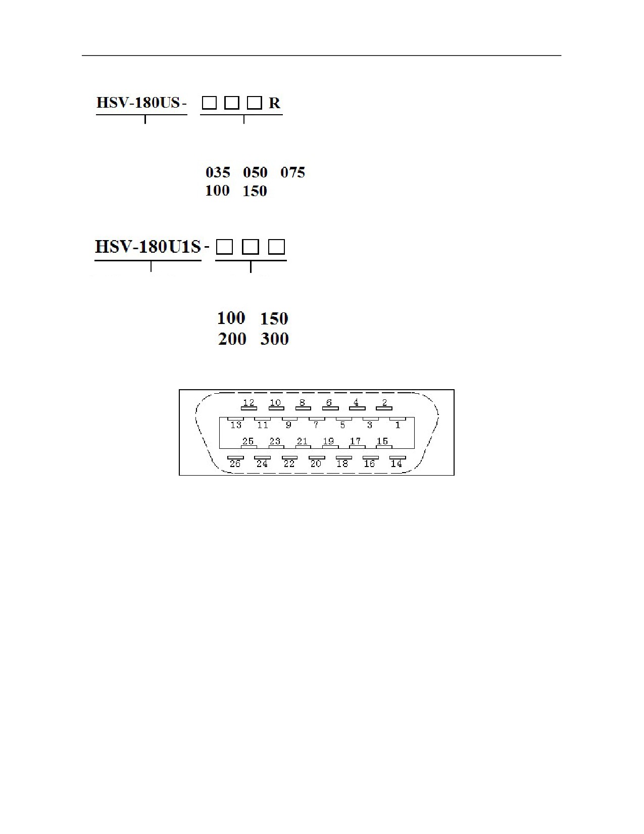
HSV-180US-035~450 spindle drive units (compatible with incremental optical encoder and incremental
sin-cos encoder)
Spindle drive unit
Specification
HSV-180US-035R~150R spindle drive units (compatible with incremental optical encoder, incremental
sin-cos encoder and rotary transformer encoder)
Spindle drive unit
Specification
HSV-180U1S-100~300 spindle drive units (compatible with incremental optical encoder and incremental
sin-cos encoder)
Input interface plug pin of XS5 spindle motor encoder
(facing the plug pin)
29
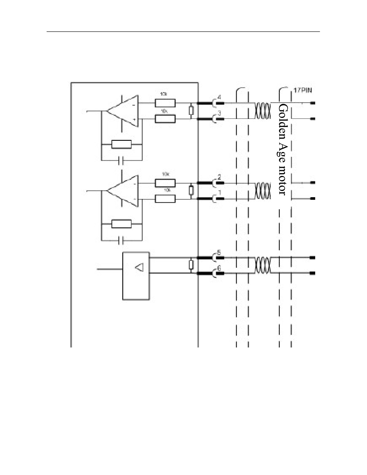
4.6.1 XS5 ENCODER1 Interface Connects to Incremental Optical Encoder
Optical encoder
30
Pin
Name
Function
Signal standard
1
A+/SINA+
Motor encoder A+ phase pulse input
2
A-/SINA-
Motor encoder A- phase pulse input
3
B+/COSB+
Motor encoder B+ phase pulse input
Wire driver and receiver
RS422 standard
4
B-/COSB-
Motor encoder B- phase pulse input
5
Z+
Motor encoder Z+ phase pulse input
6
Z-
Motor encoder Z- phase pulse input
7,8
Reserved
9,10
Reserved
11,12
Reserved
13
Reserved
26
Reserved
Power supply of motor encoder DC +5V
1. Supply +5V power to the motor encoder
16,17
connected to XS5.
+5V
DC +5V/150mA
18,19
2. Connect to the power pin of the motor encoder.
3. When cable is too long, multiple core wires
should be connected in parallel.
23,24,25
GNDD
Power ground of motor encoder 0V
20
KT+
Signal input of motor temperature sensor
22
KT_
21
Reserved
Shielding signal
14,15
PE
Connect to PE signal of motor encoder
Note: 1. Pins of the same name have been connected on the internal circuit board.
31
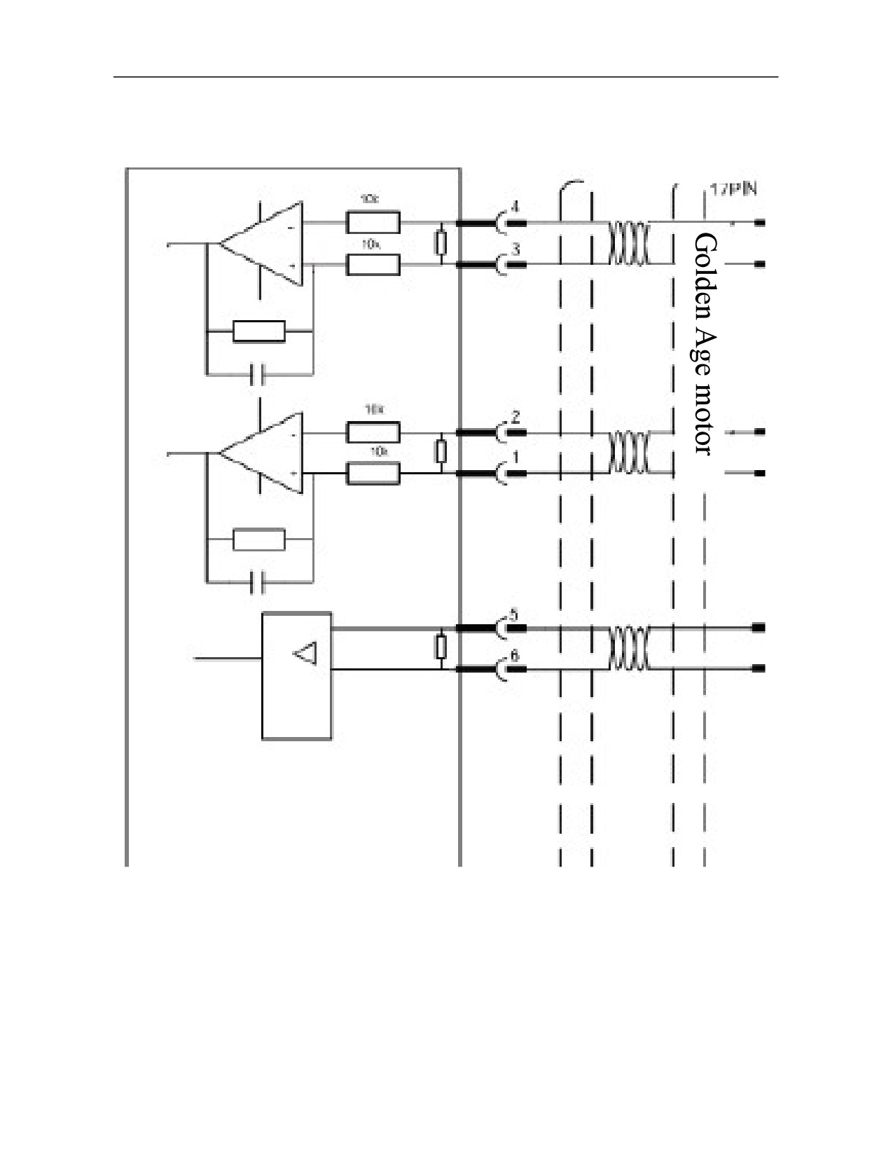
4.6.2 XS5 ENCODER1 Interface Connects to Incremental Sin-cos Encoder
Sine-cosine encoder
32
Pin
Name
Function
Signal standard
1
A+/SINA+
Motor encoder SINA+ phase pulse input
2
A-/SINA-
Motor encoder SINA- phase pulse input
3
B+/COSB+
Motor encoder COSB+ phase pulse input
Analog input voltage:
1Vp-p
4
B-/COSB-
Motor encoder COSB- phase pulse input
5
Z+/R+
Motor encoder Z+ (or R+) phase pulse input
6
Z-/R-
Motor encoder Z- (or R-) phase pulse input
7,8
Reserved
9,10
Reserved
11,12
Reserved
13
Reserved
26
Reserved
Power supply of motor encoder DC +5V
1. Supply +5V power to the motor encoder
connected to XS5.
16,17
+5V
2. Connect to the power supply pin of the motor
DC +5V/150mA
18,19
encoder.
3. When cable is too long, multiple core wires
should be connected in parallel.
23,24,25
GNDD
Power ground of motor encoder 0V
20
KT+
Signal input of motor temperature sensor
22
KT_
21
Reserved
Shielding signal is connected to PE signal of motor
14,15
PE
encoder
Note: 1. Pins of the same name have been connected on the internal circuit board.
33
4.6.3
XS5 ENCODER1 Interface Connects to Rotary Encoder
Pin
Name
Function
Signal standard
1,2
Reserved
3,4
Reserved
5,6
Reserved
7
SIN+
Motor encoder SIN+ phase input
8
SIN-
Motor encoder SIN- phase input
Analog input voltage:
2.4V- 3.0Vp-p@10kHz
9
COS +
Motor encoder COS+ phase input
10
COS-
Motor encoder COS- phase input
11
EXC1
Motor encoder EXC1 phase output
Analog output voltage:
4.8V- 6.0Vp-p@10kHz
12
/EXC1
Motor encoder /EXC1 phase output
13
Reserved
26
Reserved
16,17
Reserved
18,19
SX5 ENCODER1 interface
23,24,25
GNDD
Internal power ground 0V
20
KT+
Signal input of motor temperature sensor
22
KT-
21
Reserved
Shielding signal
14,15
PE
Connect to PE signal of motor encoder
Note: 1. Only SV-180US-035R~150R spindle drive unit can match this type of encoder.
2. Pins of the same name have been short-circuited on the internal circuit board.
3. Resolution of rotary transformer is 14bit, namely 16384 ppr.
34
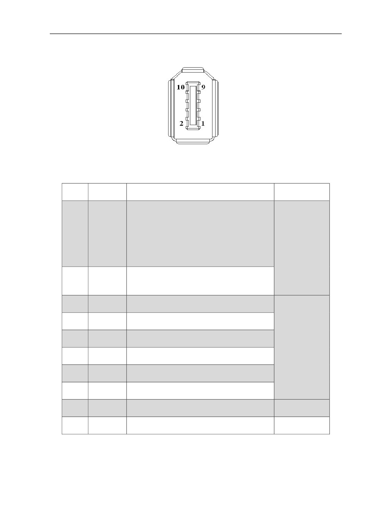
4.7 Definition of Second Encoder Interface of Spindle Servo Drive
XS6 ENCODER2 spindle encoder input interface diagram
4.7.1 XS6 ENCODER2 Interface Connects to Incremental Optical Encoder
Pin
Name
Function
Signal standard
Spindle encoder power supply DC +5V
1. Supply +5V power to the spindle encoder connected
to XS6.
1
+5V
2. Connect to the power supply pin of the spindle
encoder.
DC +5V/150mA
3. When cable is long, multiple core wires should be
connected in parallel.
1. Connect to 0V pin of the spindle encoder.
2
GNDD
2. When cable is long, multiple core wires should be
connected in parallel.
3
A+/SINA+
Connect to A+ phase of the spindle encoder
4
A-/SINA-
Connect to A- phase of the spindle encoder
5
B+/COSB+
Connect to B+ phase of the spindle encoder
Wire driver and
receiver
6
B-/COSB-
Connect to B- phase of the spindle encoder
RS422 standard
7
DATA+
Connect to Z+ phase of the spindle encoder
8
DATA-
Connect to Z- phase of the spindle encoder
9
Reserved
10
Reserved
35
4.7.2 XS6 ENCODER2 Interface Connects to Incremental Sin-cos Encoder
Pin
Name
Function
Signal standard
Power supply of motor encoder DC +5V
1. Supply +5V power to the motor encoder
connected to XS5.
1
+5V
2. Connect to the power supply pin of the
motor encoder.
DC +5V/150mA
3. When cable is too long, multiple core
wires should be connected in parallel.
1. Connect to 0V pin of spindle encoder.
2
GNDD
2. When cable is long, multiple core wires
should be connected in parallel.
3
A+/SINA+
Connect to spindle encoder SINA+
4
A-/SINA-
Connect to spindle encoder SINA-
Analog input voltage:
1Vp-p
5
B+/COSB+
Connect to spindle encoder COSB+
6
B-/COSB-
Connect to spindle encoder COSB-
7
DATA+
Connect to spindle encoder Z+ (or R+)
Analog input voltage:
0.5Vp-p
8
DATA-
Connect to spindle encoder Z- (or R-)
9
Reserved
10
Reserved
36
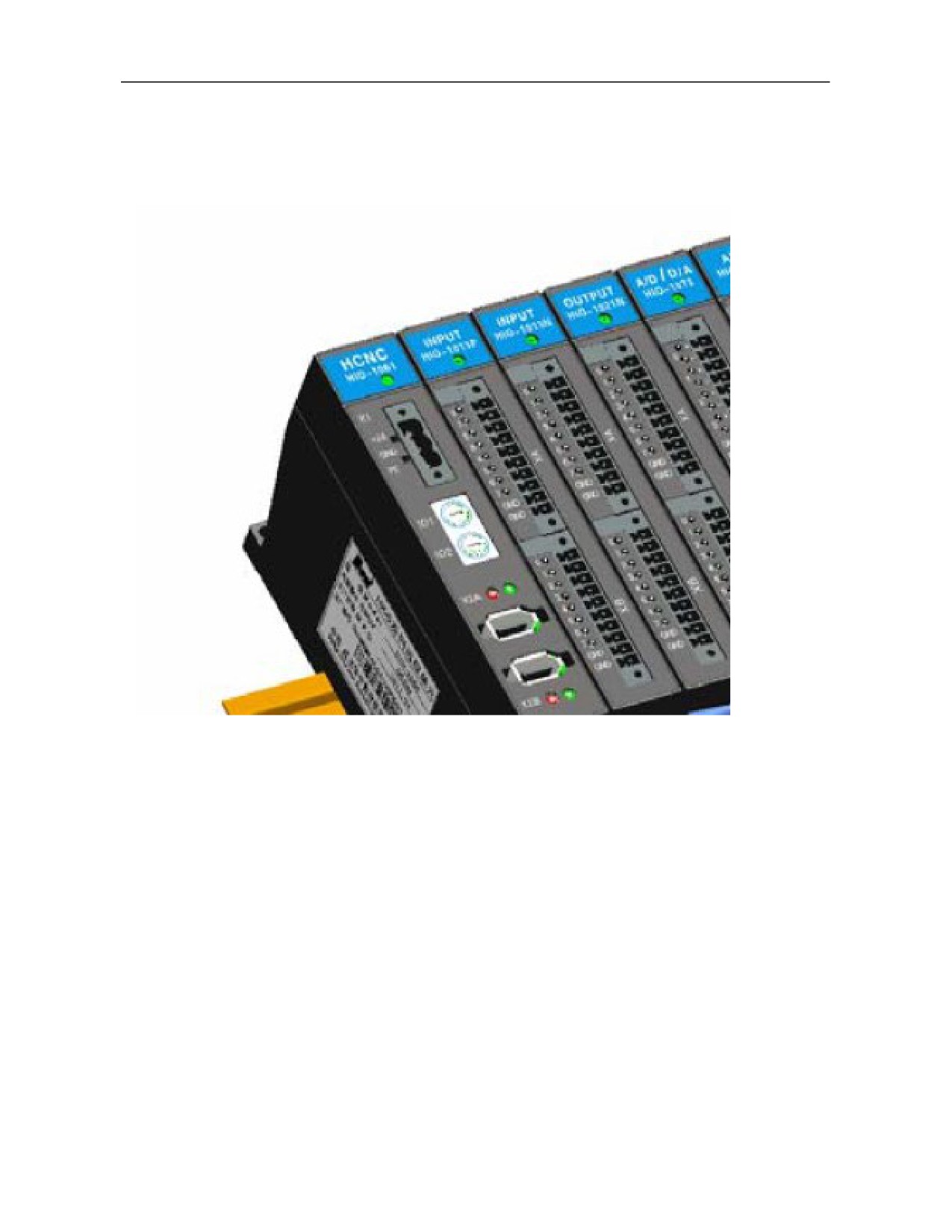
4.8 Bus I/O Unit
4.8.1 HIO-1000 Series
Installation diagram of HIO-1000B bus I/O unit
37
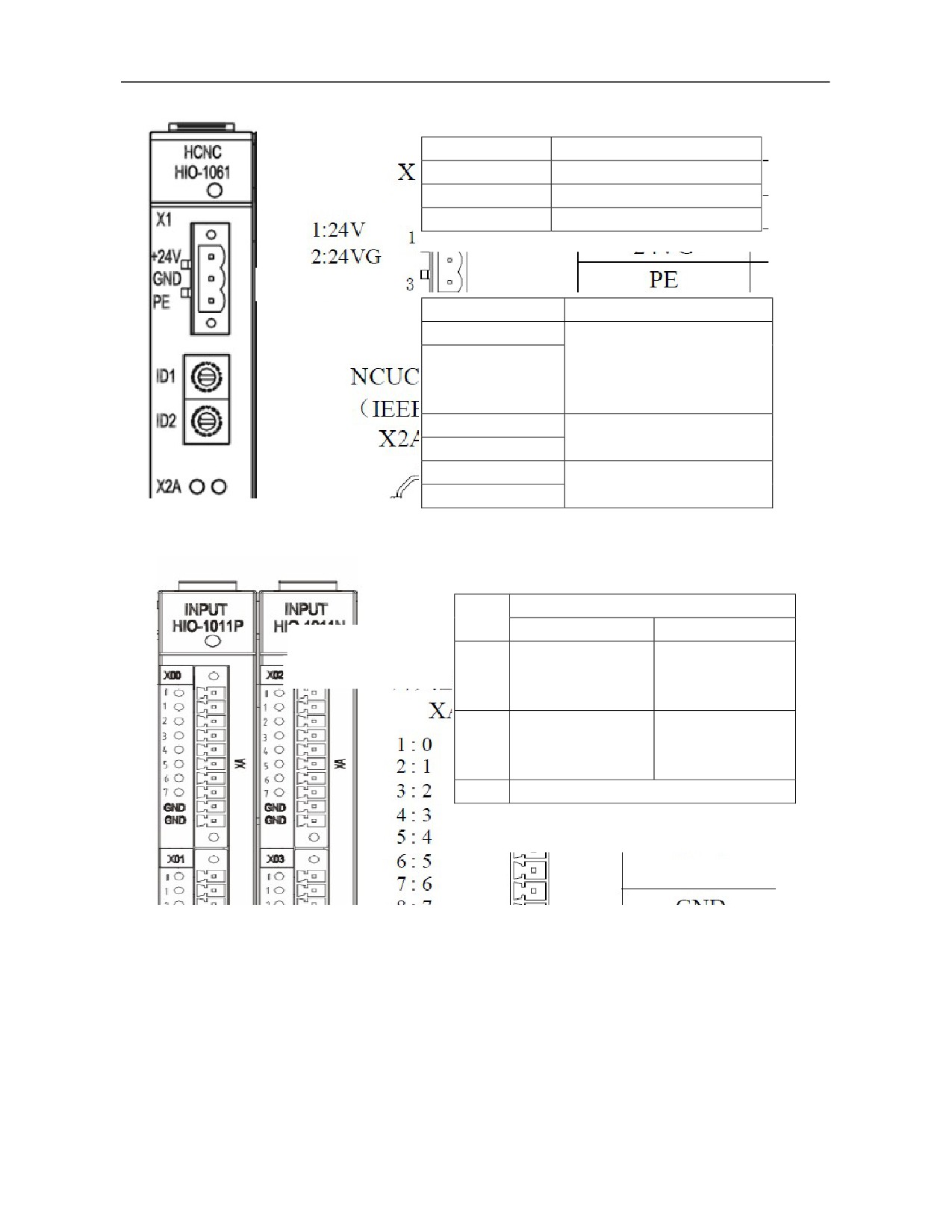
1) Definition of industrial Ethernet communication module (HIO-1061)
Signal
Description
24V
DC 24V power supply
24VG
DC 24V power ground
PE
Connect to ground
NCUC bus interface
Signal
Description
NC
The first pin and the second
pin of X2A and X2B are
NC
interconnected and they have
no electric definition.
TXD+
Data transmission
TXD-
RXD+
Data receiving
RXD-
2) Definition of switch value input/output module interface
Description
Signal
HIO-1011N XA, XB
HIO-1011P XA, XB
Switch value input
NPN input
interfaces XA and XB
0-7
N0-N7
N/A
Low level is valid
NPN input
0-7
N/A
N0-N7
High level is valid
GND
DC24V ground
Definition of input module (HIO-1011N, HIO-1011P) interface
38
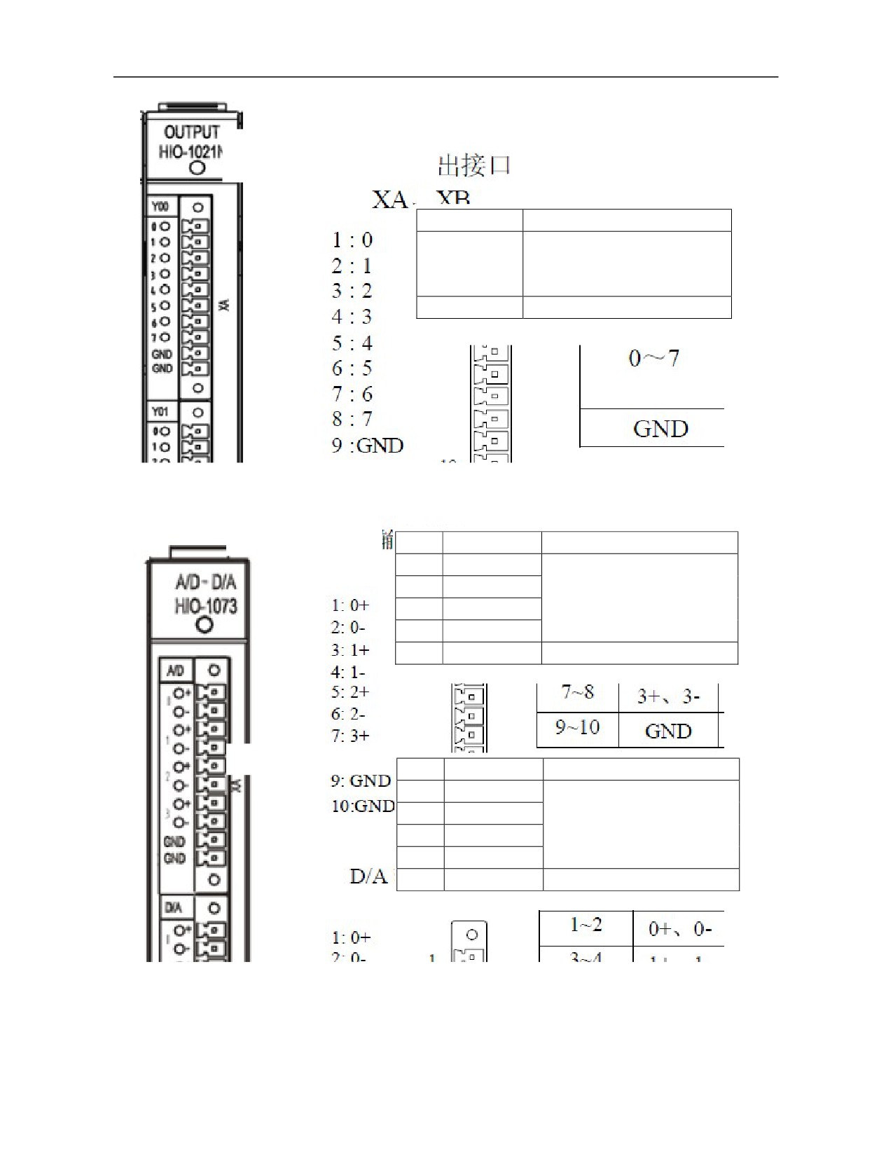
Switch value input interfaces XA
and XB
Signal
Description
NPN input
0-7
O0-O7
Low level is valid
GND
DC24V ground
Definition of output module (HIO-1021N) interface
3) Definition of analog input/output module interface
A/D input interface XA
No.
Signal
Description
1-2
0+, 0-
4 channels A/D input
3-4
1+, 1-
AD0-AD3
5-6
2+, 2-
(Input range: -10V- + 10V)
7-8
3+, 3-
9-10
GND
Ground
D/A output interface XB
No.
Signal
Description
1-2
0+, 0-
4 channels D/A input
3-4
1+, 1-
AD0-AD3
5-6
2+, 2-
(Input range: -10V- + 10V)
7-8
3+, 3-
9-10
GND
Ground
39
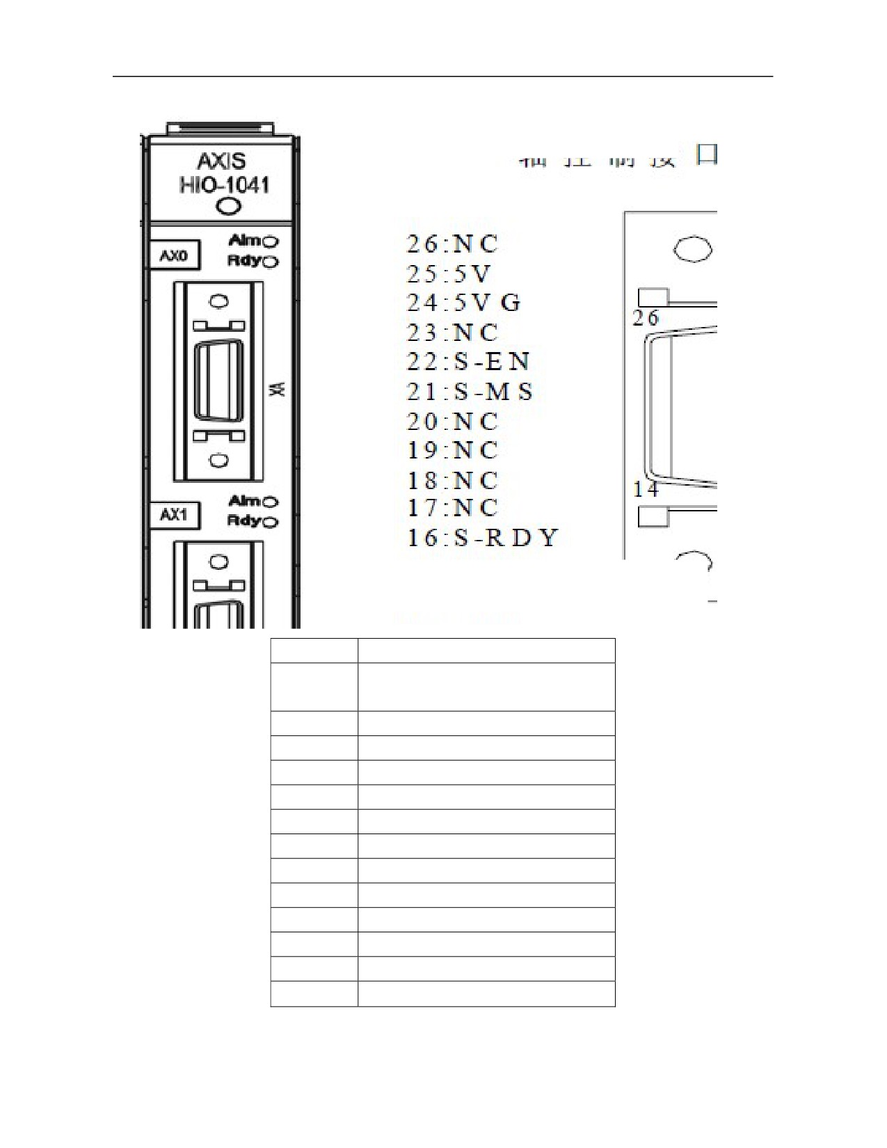
4) Definition of axis control module interface
Axis control interfaces XA, XB
Sequence of plug pins (facing soldering terminal of plug)
Signal
Description
Vcmd1+
Analog output (-10V to +10V)
Vcmd1-
PA+, PA-
Encoder A phase feedback signal
PB+, PB-
Encoder B phase feedback signal
PZ+, PZ-
Encoder Z phase feedback signal
24V, 24VG
DC24V power supply
CP+, CP-
Command pulse output (A phase)
DIR+, DIR-
Command direction output (B phase)
24VB
DC24V
S-RDY
Ready
S-MS
Mode switching
S-EN
Enable
5V, 5VG
DC5V power supply
NC
Empty
40
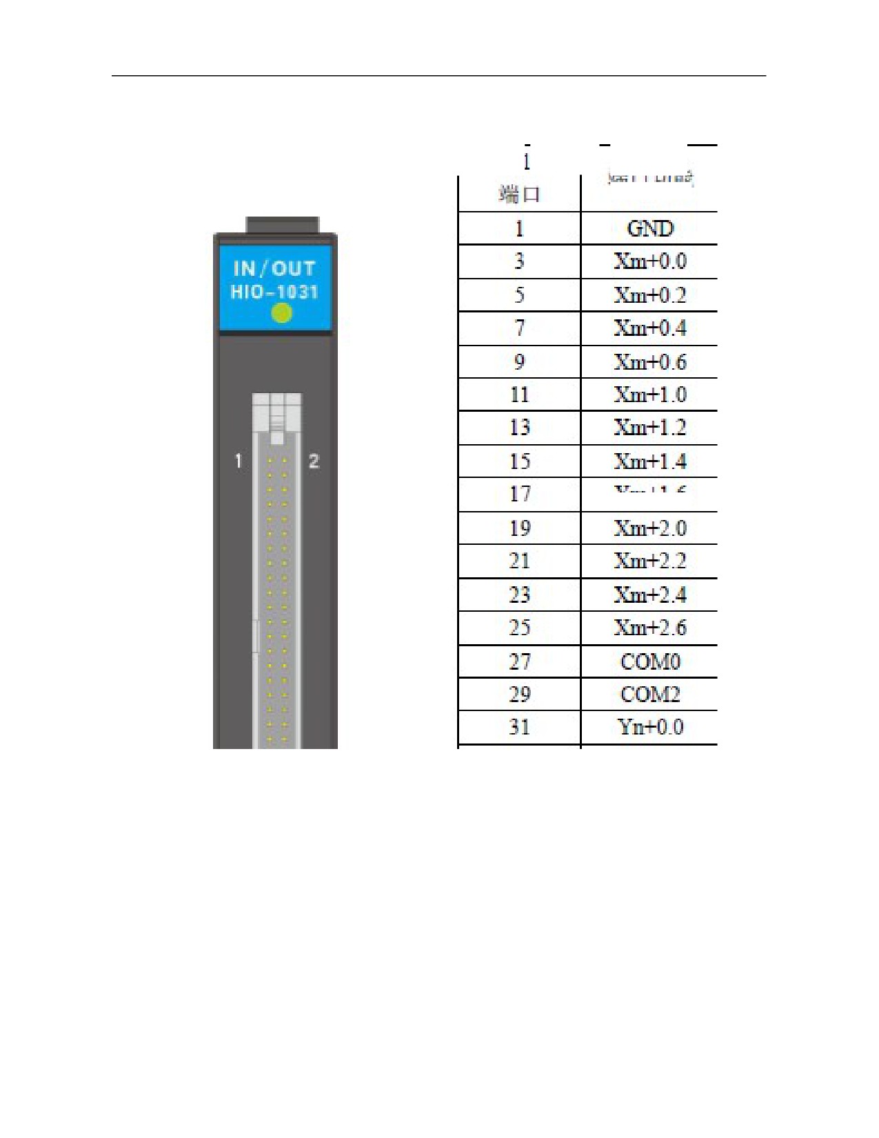
5) Definition of HIO-1031 module interface
HIO-1031
HIO-1031
Port function
Port function
port
port
+24V output
Empty
Note:
1. Three groups of input of this module occupy four groups of input points of the system, 8 bytes for each group,
and the last group is reserved by default. Two groups of output occupy two groups of output points.
2. If the input configuration ports COM0 to COM2 are empty, PNP type is defaulted.
3. If COM0 port is connected to GND, Xm+0.0 ~ Xm+0.7 can be configured as PNP type input. If COM0 port
is connected to 24V, Xm+0.0 ~ Xm+0.7 can be configured as NPN type input. Likewise, Xm+1.0 ~ Xm+1.7
and Xm+2.0 ~ Xm+2.7 corresponding to COM1 and COM2 can be configured as PNP type input or NPN type
input. Please configure COMx port under power off and restart to validate it.
4. It is valid when the current flowing through the input port is greater than 6mA.
41
4.8.2 HIO-1200 Series
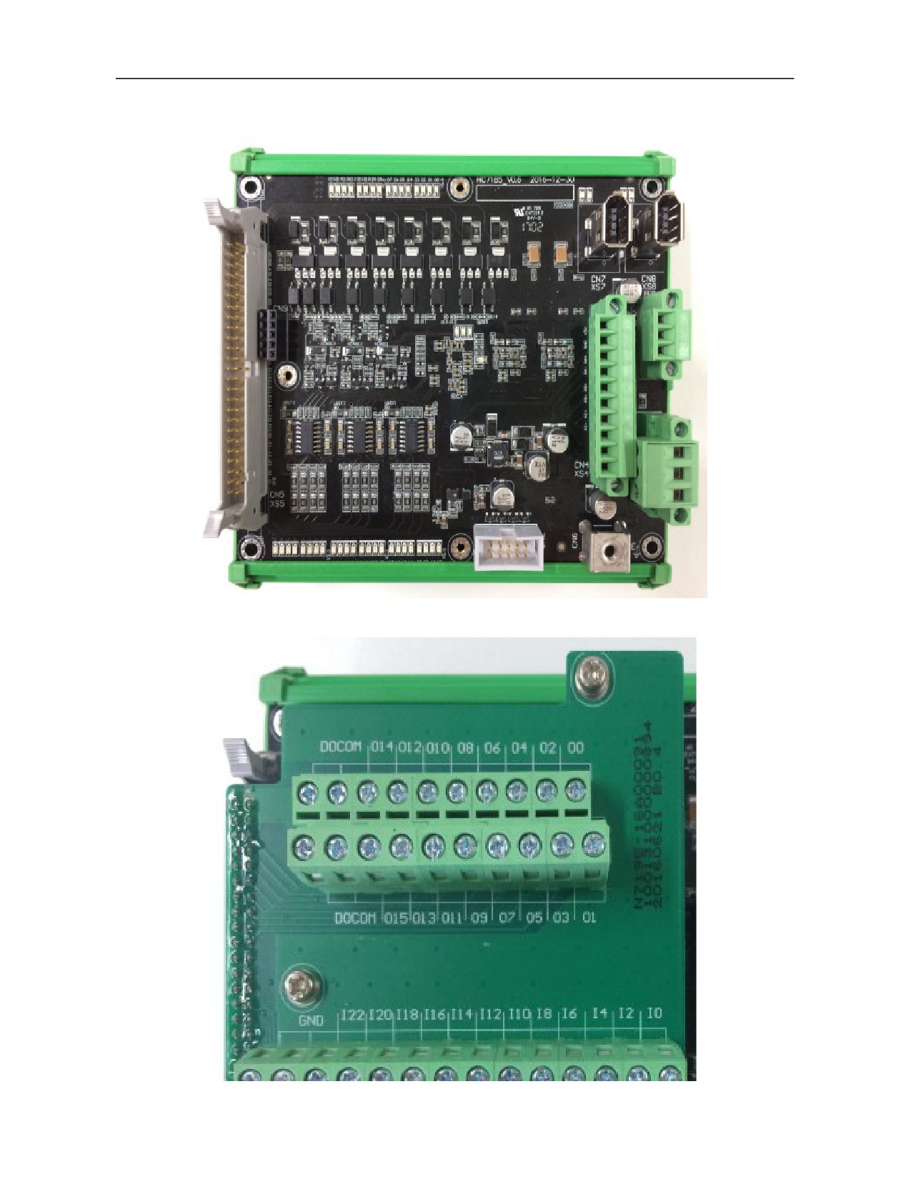
HIO-1200 picture
42
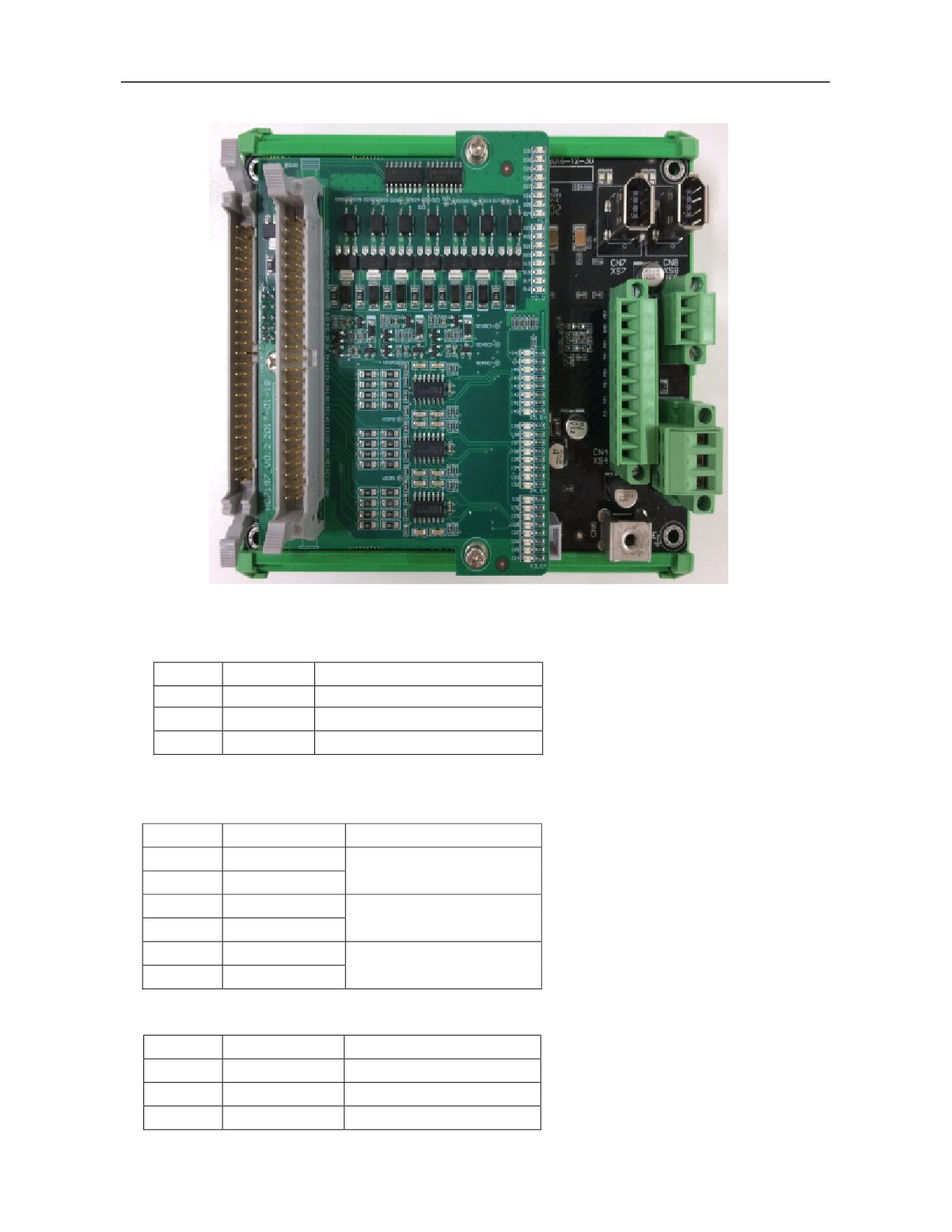
HIO-1200-M1 picture
HIO-1200-M2 picture
1) Power supply interface XS1
XS1: Power supply interface, pin is defined as below:
Pin
Signal
Port function
1
+24V1
DC24V power supply input
2
GND
GND
3
PE
PE
2) Bus interfaces XS7 and XS8
XS7-XS8, NCUC bus interface is defined as below:
Pin
Signal
Port function
1
24V
DC24V power transmission
2
GND
3
TXD+
Data transmission
4
TXD-
5
RXD+
Data receiving
6
RXD-
3) Analog spindle interface XS3
Pin
Signal
Port function
1
DA+
Analog output +
2
DA-
Analog output -
3
AG1
Analog PE
43
4) Encoder input interface XS4
Pin
Signal
Port function
1
+5V
5V output
2
GND
GND
3
PA1+
PA1+
4
PA1-
PA1-
5
PB1+
PB1+
6
PB1-
PB1-
7
PZ1+
PZ1+
8
PZ1-
PZ1-
9
NC
Null
10
NC
Null
5) Digital input/output interface XS5
Pin
Symbol
Port function
Pin
Symbol
Port function
1
GND
GND
2
+24V
24V output
3
I0
X0.0
4
I1
X0.1
5
I2
X0.2
6
I3
X0.3
7
I4
X0.4
8
I5
X0.5
9
I6
X0.6
10
I7
X0.7
11
I8
X1.0
12
I9
X1.1
13
I10
X1.2
14
I11
X1.3
15
I12
X1.4
16
I13
X1.5
17
I14
X1.6
18
I15
X1.7
19
I16
X2.0
20
I17
X2.1
21
I18
X2.2
22
I19
X2.3
23
I20
X2.4
24
I21
X2.5
25
I22
X2.6
26
I23
X2.7
27
COM0
COM port of X0
28
COM1
COM port of X1
29
COM2
COM port of X2
30
NC
Null
31
O0
Y0.0
32
O1
Y0.1
33
O2
Y0.2
34
O3
Y0.3
35
O4
Y0.4
36
O5
Y0.5
37
O6
Y0.6
38
O7
Y0.7
39
O8
Y1.0
40
O9
Y1.1
41
O10
Y1.2
42
O11
Y1.3
43
O12
Y1.4
44
O13
Y1.5
45
O14
Y1.6
46
O15
Y1.7
47
DOCOM
24V input
48
DOCOM
24V input
49
DOCOM
24V input
50
DOCOM
24V input
1. Please share 0V with pin 1 (GND) of I/O interface CN5 and input signal source. Pin 2 (+24V) of CN5 is 24V
output inside the board and is used for input type configuration only. If pin 27 (COM0) of CN5 is empty or
grounded, pins I0-I7 can be configured as PNP type input. If COM0 is connected to 24V, pins 10-17 can be
44
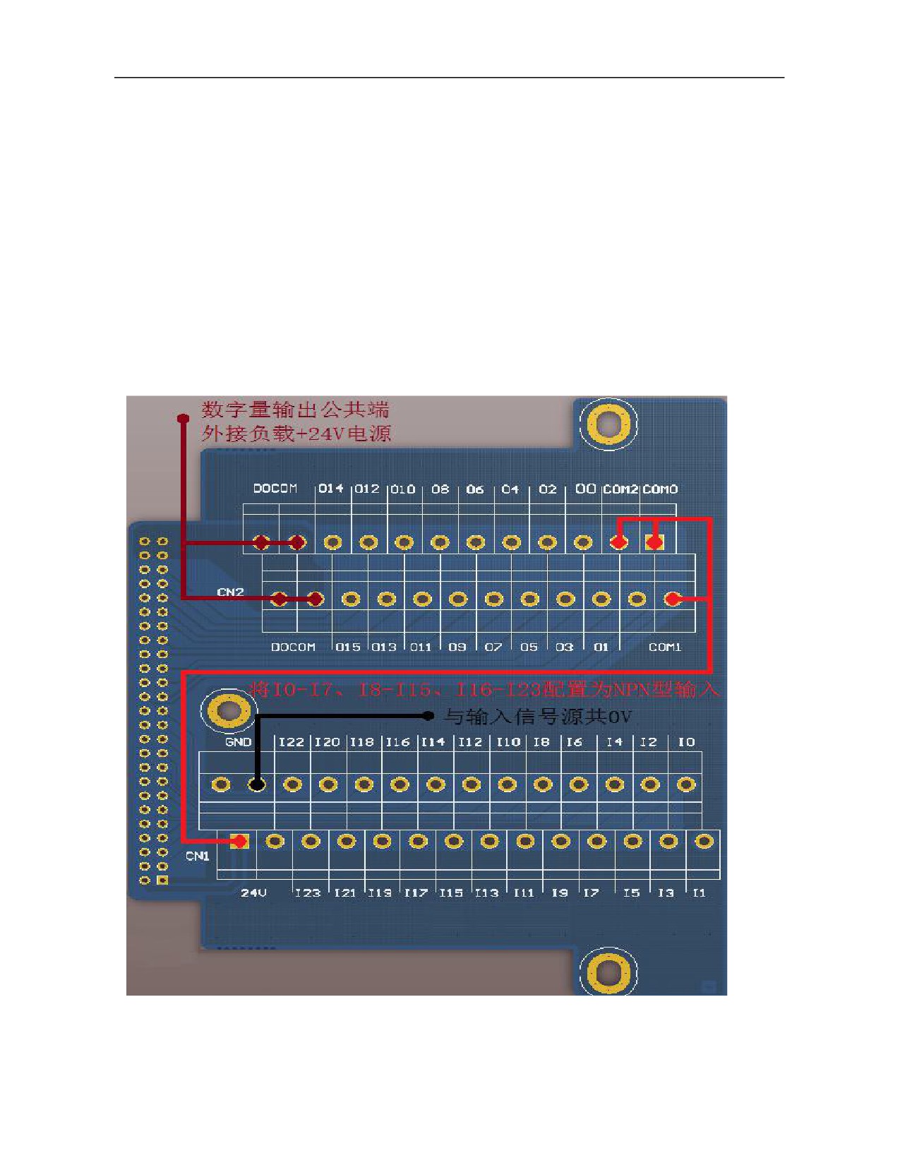
configured as NPN type input. Likewise, COM1 can be configured for I8-I15 pin input types and COM2 can be
configured for I16-I23 pin input types. Please configure COMx port under power-off state and restart to validate it.
Pins I0-I7 correspond to X0, pins I8-I15 correspond to X1 and pins I16-I23 correspond to X2. Definition and
usage of I/O extension board interface is similar to baseboard. The PNP type input is valid when greater than 19V
and NPN type input is valid when less than 4V.
2. Pins 47-50 (DOCOM) of I/O interfaces are digital output common ports and are connected to load +24V power
supply externally. The rated current of PNP digital output is 100mA. If it is ≧140mA, output port will undergo
overcurrent protection. Restart to recover it after fault removal. Capacity of load +24V power supply is determined
according to total quantity of I/O and load power and must not be connected to the one-way load greater than 120mA
for a long time to avoid irreversible damage.
Additional Description:
Picture of HIO-1200-K terminal board where I0-I7, I8-I15 and I16-I23 are set as NPN type input:
Digital output command terminal
External load +24V power supply
45
5. Preparation for Commissioning
5.1 Verification and Record
Please check whether objects are consistent with purchase order and packing list. If not, please contact HCNC
company immediately.
5.2 View System Information
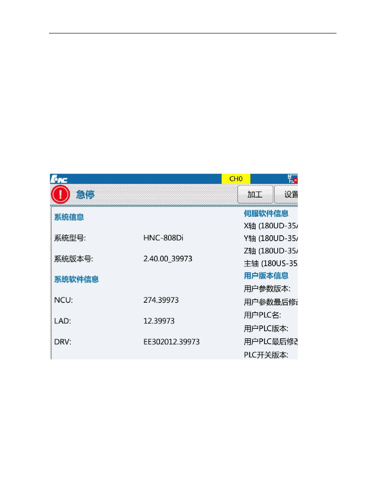
Steps for viewing HNC-8 software version information: Press "Maintain" on the MDI panel→F8 "System
information". The system information page displays system information, system software information, servo
software information and user version information.
5.3 Software Upgrade and Parameters, PLC Backup/Loading
HNC-8 software upgrade includes application program upgrade, parameter upgrade, PLC upgrade and BTF
full-package upgrade.
For parameter, PLC or BTF full-package upgrade, users need to back up PLC and parameters first. Otherwise,
PLC and parameters in the original system will be covered by standard parameters and PLC after upgrade is
completed.
46
5.3.1
Parameters and PLC Backup
Operating steps:
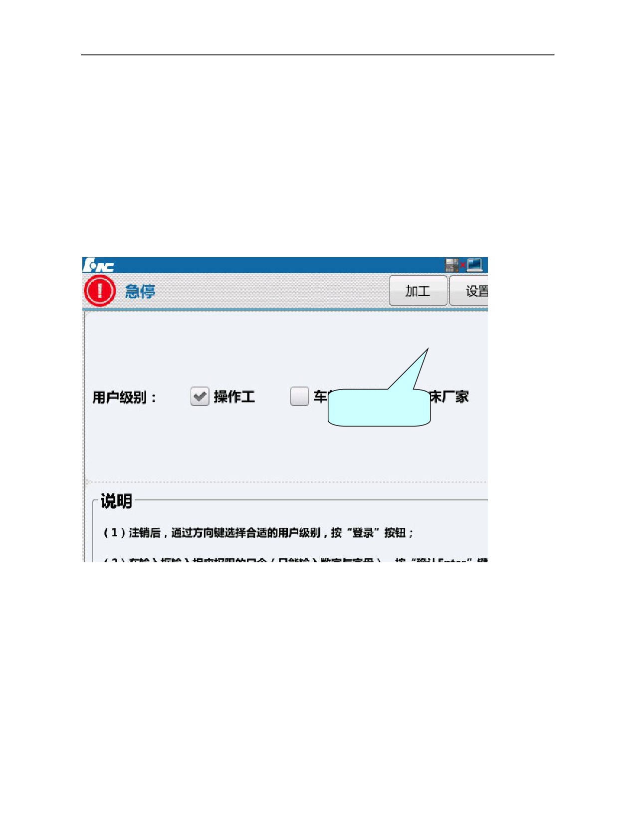
1) Press "Maintain" on the MDI panel→ press F9 "Permission management"→ press F4 "Logout"→select user
level (the backup is allowed only for workshop manager or above) → press F2 “Login”→Enter the password→
press "Enter" on the MDI panel to confirm (if the permission password is correct, parameter of this level can be
modified; otherwise, the system will give a prompt message "Incorrect password".) ;
Default permission password:
Operator: Need not to enter a password
Workshop manager: GOD
Machine tool manufacturer: HOG
CNC manufacturer: HIG
System administrator: HNC8
Enter administrator
password
2) Press F1 "↑" to return-Press F7 "Data management";
3) Select type of data to be backed up by “↑”, “↓”, “←” and “→” in the MDI panel. e.g.: To back up parameter
file, select "Parameter file". To back up PLC file, select "PLC file". Then, press "Enter" on the MDI panel to
confirm and “√” is displayed in front of corresponding item;
47
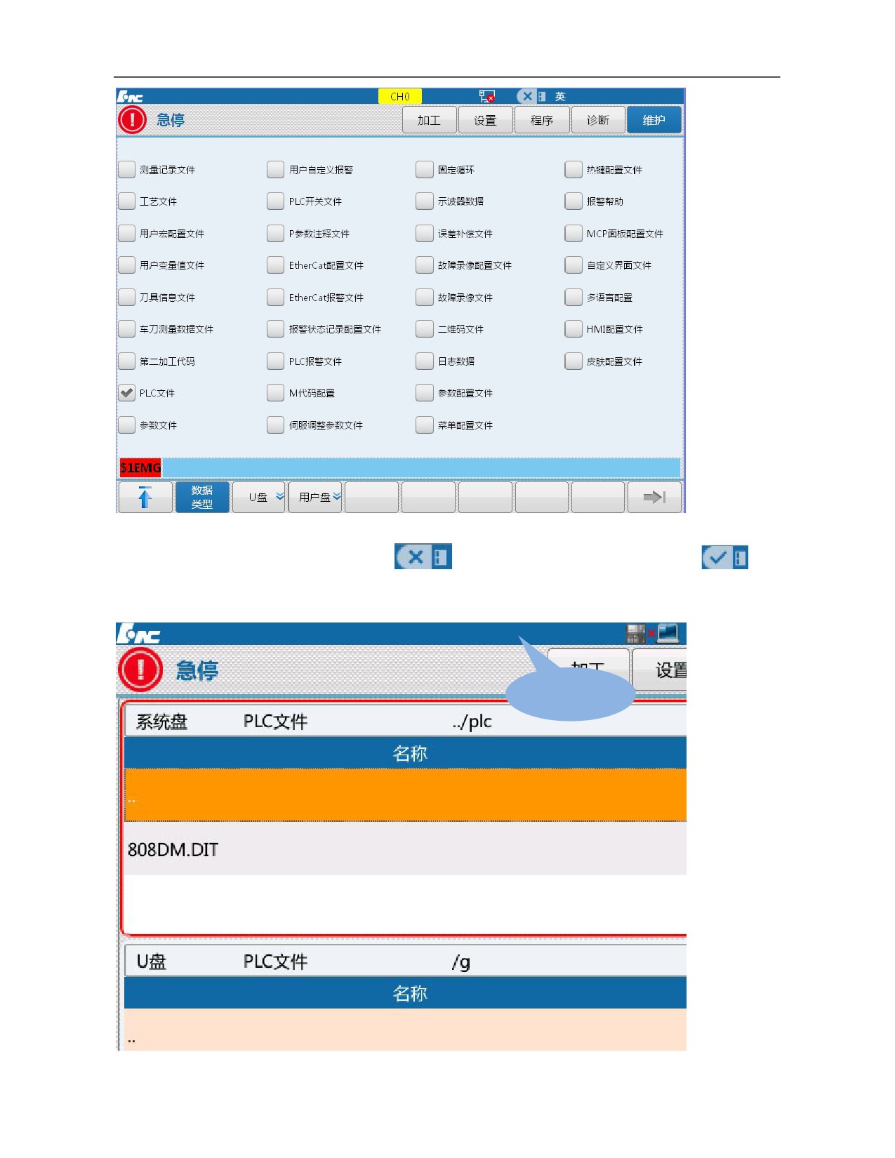
4) Select the backup path by "USB flash disk" and "User disk". For backup in USB flash disk, insert USB flash
disk into USB interface of the system. When
in the upper part of the screen turns to
, it
means that USB flash disk has been loaded;
USB flash disk
has been loaded
5) Press F9 "Window switch" and the window returns to "System disk";
48
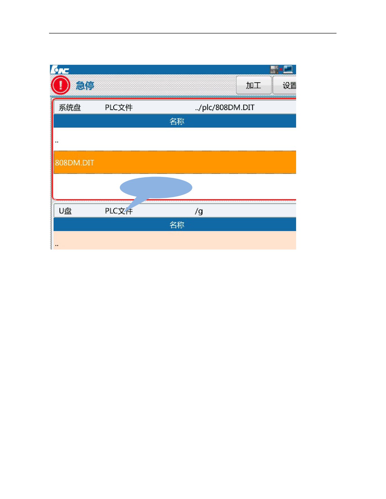
6) Press F3 "Backup" and the system will give a prompt message "Whether to back up the selected file? (Y/N)",
"Y": Yes, "N": No, which correspond to "Y" and "N" on the MDI panel. Select Y and the system will give a
prompt message that the backup succeeds, and generates corresponding file name suffixed with date and time.
Generated backup
file
5.3.2 Software Upgrade
Note: For the sake of safety, it is better to disconnect the bus at the rear of the system after PLC or
parameter upgrade; otherwise, standard PLC or parameter may differ from current machine tool and
consequently the machine tool works abnormally
1) Enter permission as per operating step 1) in 4.3.1;
2) Press "Maintain" on the MDI panel→ press F7 "System upgrade";
49
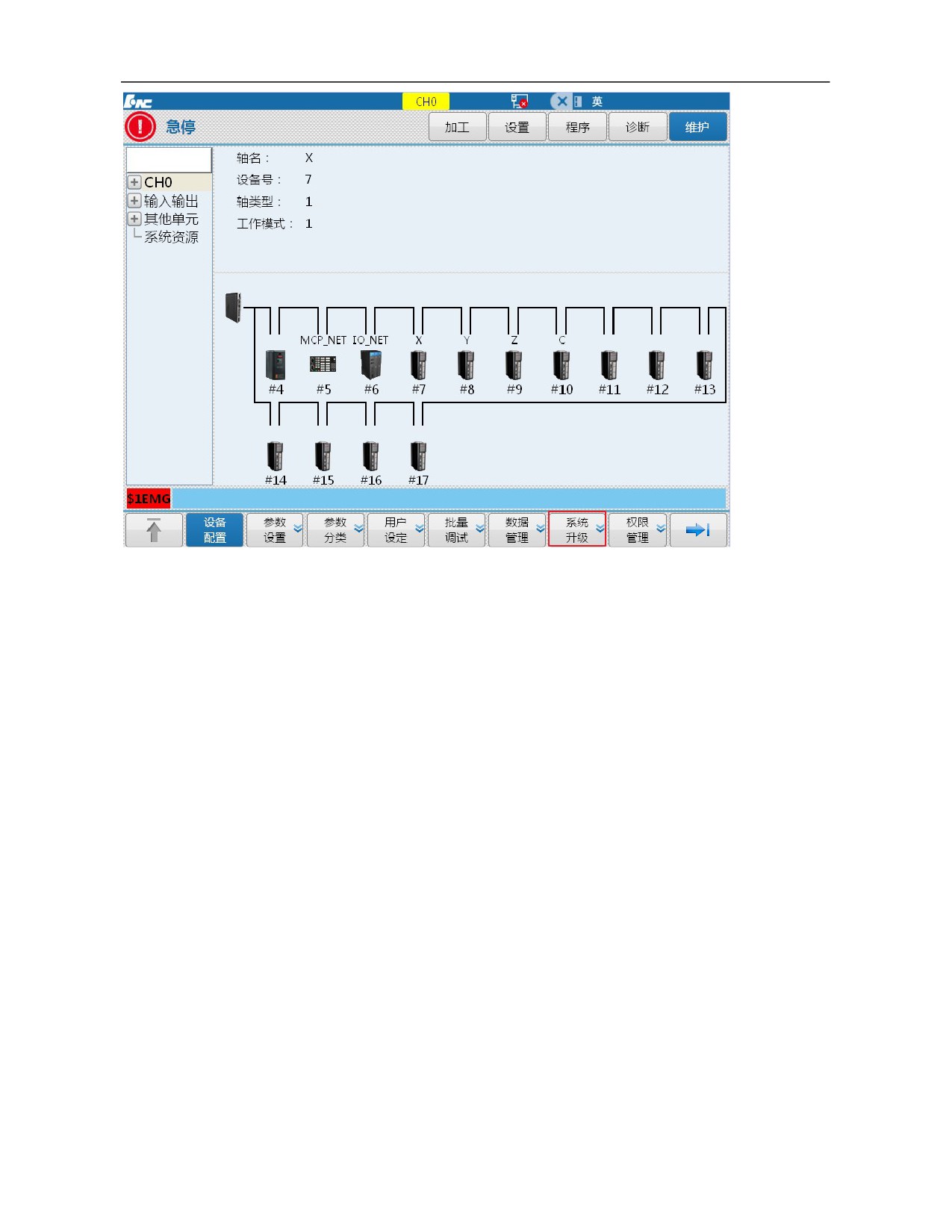
3) Press "Window switch" to switch to the upgrade option and select "Type of upgrade option" and "Backup
or not" by “↑”, “↓”, “←” and “→” on the MDI panel: Application program, parameter, PLC and BTF. Generally,
select BTF upgrade and then press "Enter" on the MDI panel to confirm. Backup or not: Select whether backup
is needed according to actual situation. After selection, “√” is displayed in front of corresponding option.
4) Select USB flash disk, switch to USB flash disk directory by "Window switch" and select corresponding
upgrade patch by “↑” and “↓” on the MDI panel. After selection, press "Enter" on the MDI panel to confirm. If
the backup is selected, the system will start the backup automatically and corresponding file to be backed up
will be saved in the path of CF card. After the backup is completed, the system will start the automatic
verification of upgrade patch after passing the verification. After upgrade is completed, the system will give a
prompt message "Upgrade succeeds, please power off and restart". After the system is powered off and restarted,
the loaded file is validated.
50
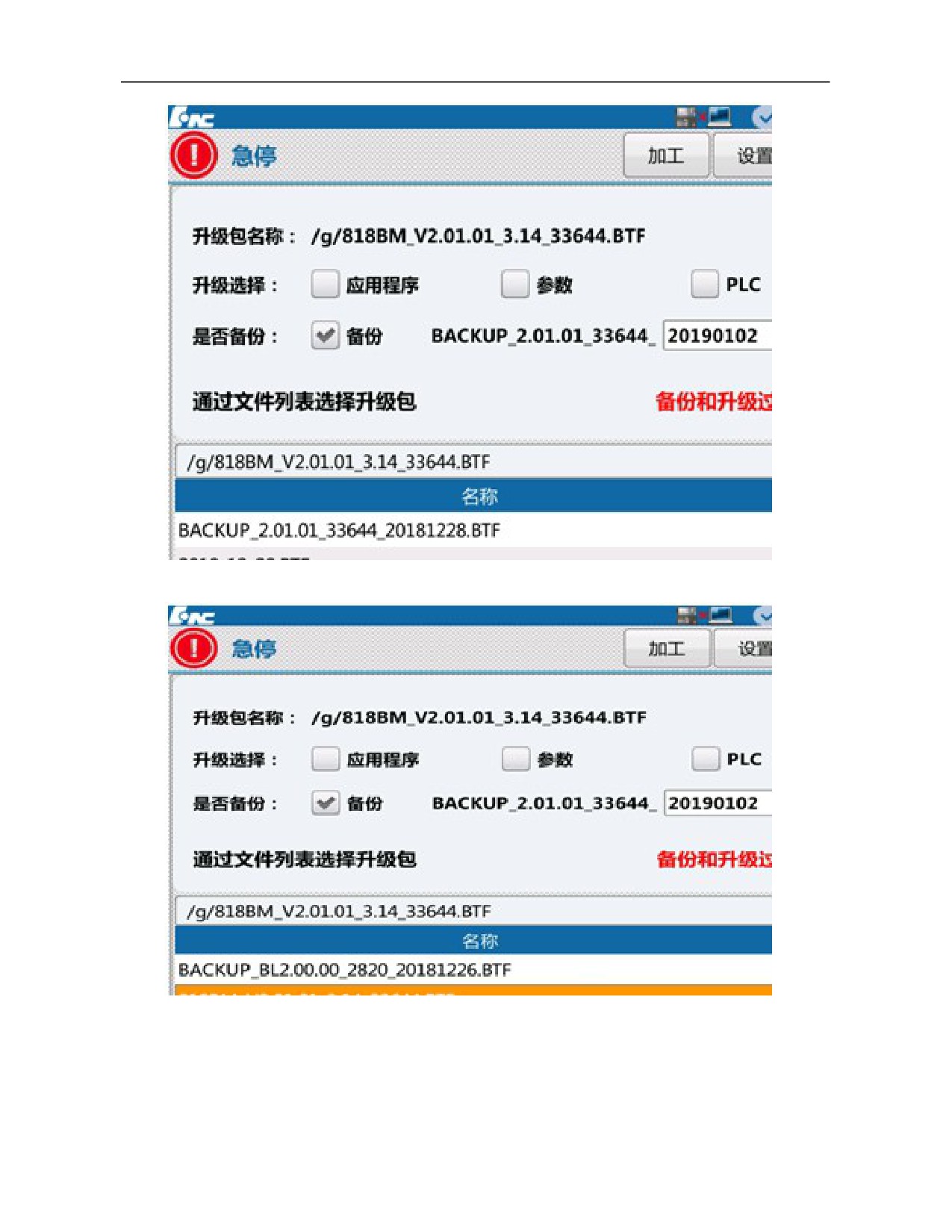
Select corresponding upgrade package file in the USB flash disk
Upgrade completed
5.3.3 Parameters and PLC Loading
Operating steps:
1) Enter permission as per operating step 1) in 4.3.1;
51
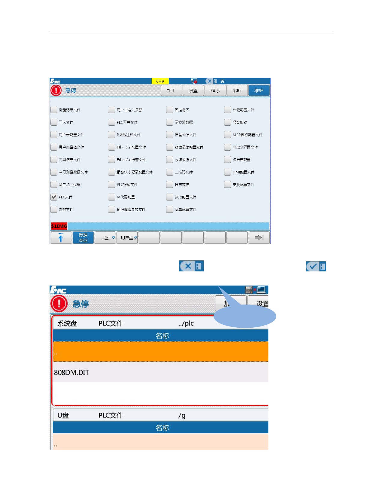
2) Press F1 "↑" to return→Press F7 "Data management";
3) Select type of data to be loaded by “↑”, “↓”, “←” and “→” on the MDI panel. e.g.: To load parameter file,
select "Parameter file". To load PLC file, select "PLC file". Then, press "Enter" on the MDI panel and "√" is
displayed in front of corresponding option;
4) Select the loading path by "USB flash disk" and "User disk". For loading from USB flash disk, insert USB
flash disk into USB interface of the system. When
in the upper part of the screen turns to
,
it means that USB flash disk has been loaded;
USB flash disk has
been loaded
52
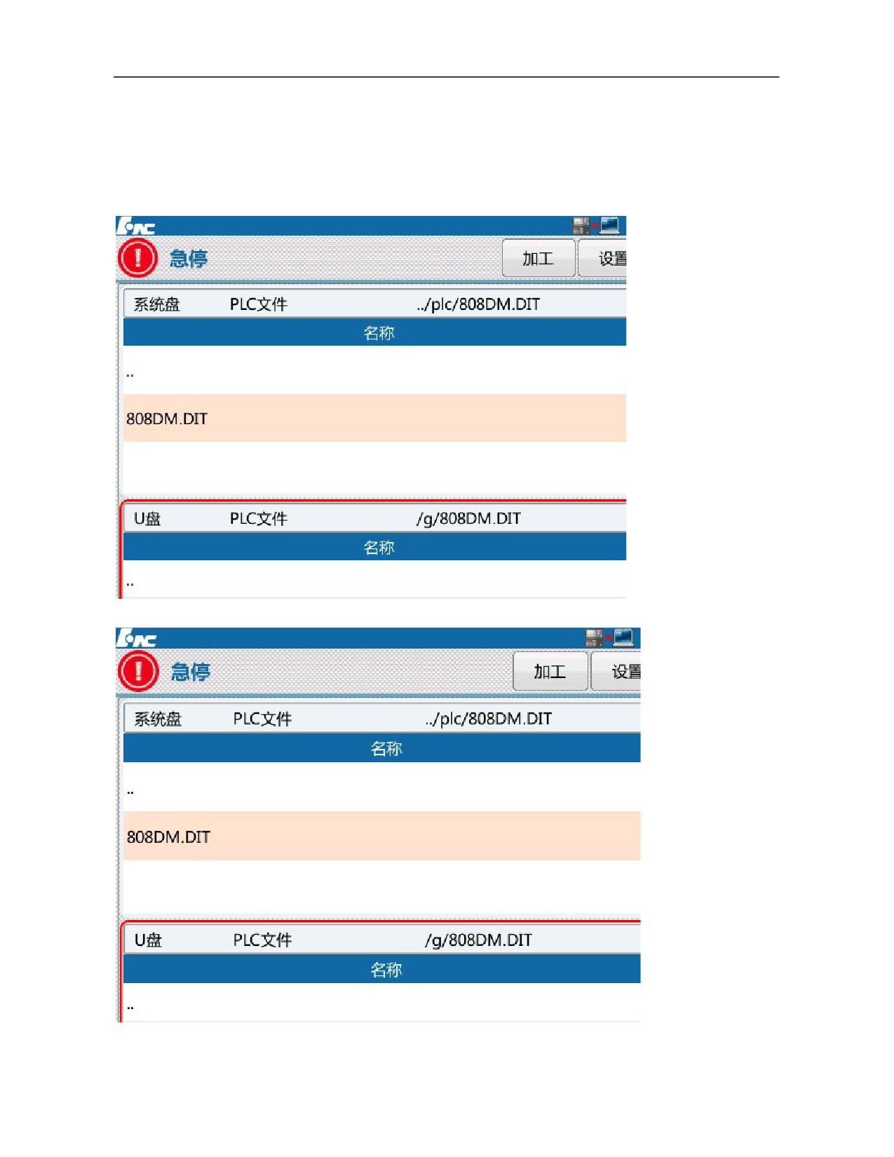
5) Select the file to be loaded by “↑” and “↓” on the MDI panel, press "Load" and the system will give a
prompt message "Whether to load the selected file? (Y/N)", "Y": Yes, "N": No, which correspond to "Y" and
"N" on the MDI panel. Select Y and if there is a file of the same name in the system, the system will give a
prompt message "Whether to cover the file? (Y/N)", select Y and the system will start to load the file. After the
file is loaded, the system will give a prompt message "Loading succeeds and the system has been restarted!".
After the system is powered off and restarted, the loaded file is validated.
A prompt whether to load the selected file will be given
A prompt whether to cover the original file will be given
53
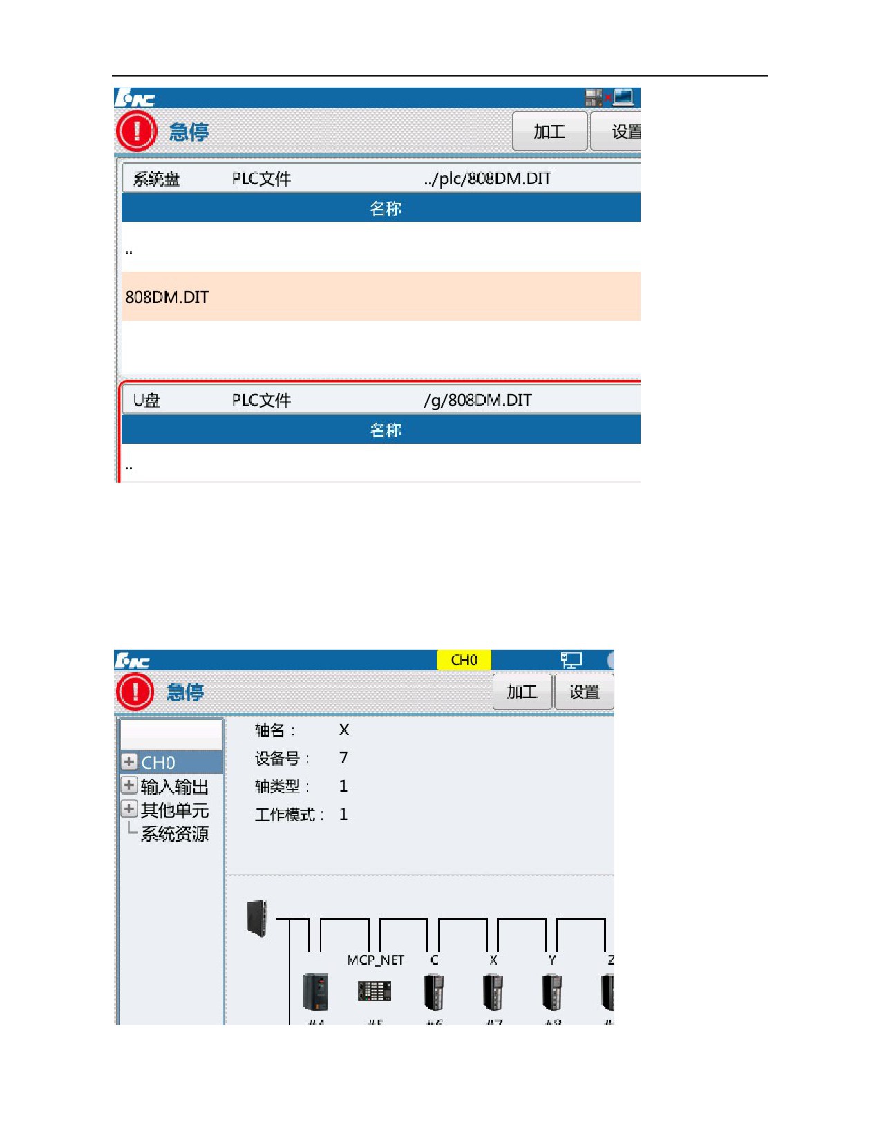
A prompt loading succeeds and restart the system will be given
5.3.4 Batch Commissioning
Batch commissioning procedures for HNC-8 series of standard configurations will be described in this chapter.
Operating steps:
1) Enter permission as per operating step 1) in 4.3.1;
2) Press F1 “↑” to return→ press F6 “Batch commissioning”;
3) Select a single parameter type or multiple parameter types by "Enter" on the MDI panel;
54
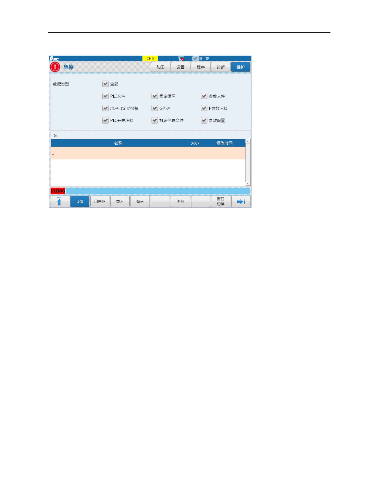
Select path of load and backup by F2 “USB flash disk” and F3 “User disk”;
Select corresponding operation by F4 "Load" and F5 "Backup".
4) This function is mainly used for commissioning of several machine tools. When a machine tool reaches the
correct condition, back up all parameters in a USB flask disk according to the above steps. Then, insert the USB
flask disk into a machine tool system to be commissioned and load parameters in the USB flask disk in the
system according to the above steps. Optimization and commissioning of the machine tool have been completed.
The machine tool manufacturer can start inspection.
Note:
1. For this function, the CNC controller type, drive and motor types, electric points, and machine tool type must
be consistent.
2. This function must ensure consistency of system version number.
5.4 Offline Commissioning
In order to prevent an accident, drive and motor should undergo offline commissioning before connected to
actuator.
This step is extremely important while commissioning large machine tools.
Specific steps:
1) Place drive and motor in a flat and safe position (such as ground);
2) Connect drive and motor only, set the drive as the internal enable (for details, refer to User Manual of
HSV-180UD AC Servo Drive Unit) and test operating condition;
Note: If an absolute motor rotates automatically after powered on, it means that zero setup is needed.
(For specific steps of zero setup, please refer to User Manual of HSV-180UD AC Servo Drive Unit)
3) Connect the system to drive and drive to motor (for details, please refer to Hardware Connection
Specification), as shown in Fig. 1.3. Recover drive parameters to the external enable and determine whether
communication is normal through observing drive light or viewing device interface, (to view device interface
parameters, refer to 3.1). If parameters of some devices cannot be displayed, connect them and eliminate faults
one by one.
55
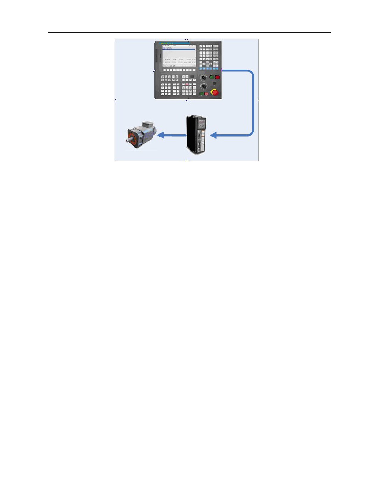
Fig. 1.3 Offline commissioning
Other key points of commissioning:
Check whether phase sequences U, V and W of power line are correct. For Golden Age absolute motor,
phase sequence should be U, W and V. For Huada absolute motor, phase sequence needs not to be
exchanged.
Check whether the CNC controller can control action of drive and motor correctly and whether drive and
motor are stable and reach designed power;
4) Commission PLC and check emergency stop points;
5.5 Step-by-step Power-on Principle
In order to ensure safety of commissioning personnel and intactness of machine tool and for ease of fault
diagnosis, comply with "step-by-step power-on" principle in the earlier commissioning period:
1) Power on the CNC controller and power off other parts. Check parameters and PLC and ensure correctness
of power-on parts of PLC, especially when the gravity axis brakes.
2) Power on the feed axis and check whether device cables are connected correctly and whether the drive and
the system are connected normally;
3) Power on the power device (motor) and check whether the motor is controlled normally, whether the
machine tool works normally and whether all limits are valid;
4) Power on the spindle module and check whether the spindle speed is normal;
5) Power on the magazine module and check correctness of tool change;
5.6 HNC-8 System Boot Failure and Cause
Fault and cause that the system returns to Linux backstage after startup
1. Return to the backstage and there is printed information: Step 1/11: KernelInitErr
Cause: System kernel failed to apply for memory.
Solution: System memory failure.
2. Return to the backstage and there is printed information: Step 2/11: ReadCfgErr
56
Cause: Error occurs while reading system configuration file LNC32.CFG file.
Solution: Load normal LNC32.CFG file.
3. Return to the backstage and there is printed information: Step 3/11: NcguiErr
Cause: System memory is insufficient and interface startup fails
Solution: System memory failure.
4. Return to the backstage and there is printed information: Step 3/11: BmpLoadErr
Cause: System memory is insufficient and BMP picture module initialization is abnormal
Solution: System memory failure.
5. Return to the backstage and there is printed information: Step 3/11: FontErr
Cause: Loading word stock fails and word stock file may be missing or damaged
Solution: Load a correct word stock file
6. Return to the backstage and there is printed information: Step 4/11: ParmXmlLoadErr
Cause: Loading parameter configuration file PARM-CN.XML fails
Solution: Re-copy a normal PARM-CN.XML file to the system
Note: After returning to Linux backstage, characters still can be entered by keyboard normally. Due to Bug of
Linux system, characters printed after returning to Linux system for the first time are invisible. When power is
not off, start software of the CNC system manually, the system will return to Linux backstage again and users
can see the printed incorrect characters.
How to start the software of the CNC system:
Enter "cd /h/lnc8” in the # interface and press the return key.
Enter "./n” in the # interface and press the return key.
If the start interface is normal, red color on the interface displays the abnormal start
1.
Red color displays: 3---Interface initialization fails [2]
Cause: There is damaged file or missing file in BMP files
Solution: Replace BMP files again.
2.
Red color displays: 4---Parameter initialization fails [-2]
Cause: Parameter "Original file and backup file are damaged (file verification fails) or "Two files have
inconsistent data".
Solution: Alarm is eliminated after system restart. If the alarm is still not eliminated after system restart,
enter "Data management" menu, delete backup file and restart the system. If the alarm still cannot be
eliminated, re-import a normal parameter file to the system.
3.
Red color displays: 5---Program manager initialization fails [-1]
Cause: System memory is insufficient
Solution: System memory failure.
4.
Red color displays: 6---PLC initialization fails [-1]
Cause: Loading DIT ladder diagram to the system fails
Solution: Ladder diagram file is damaged
5.
Red color displays: 7---Alarm module initialization fails [-2]
Cause: Opening grammatical alarm text SYTAX.ERR fails
Solution: The system imports a normal SYTAX.ERR file
6.
Red color displays: 7---Alarm module initialization fails [-3]
Cause: Opening system alarm text SYS.ERR fails
Solution: The system imports a normal SYS.ERR file
7.
Red color displays: 8---Saving previous power-off data fails, please check UPS power [0x0010]
Cause: Data is not stored normally after system power-off
57
Solution: UPS is not fully charged or UPS is abnormal
8. Red color displays: 8---Data file import module initialization fails [0x0001]
Cause: Workpiece coordinate system CRD.DAT file of the system, "Original file and backup file are
damaged (file verification fails)" or "Two files have inconsistent data".
Solution: Alarm is eliminated after system restart. If alarm is still not eliminated after system restart, reset
the workpiece coordinate system and restart the system.
9. Red color displays: 8---Data file import module initialization fails [0x0002]
Cause: Loading system tool file TDATA.DAT file fails
Solution: Alarm is eliminated after system restart. If alarm is still not eliminated after system restart, reset
tool data and restart the system.
10. Red color displays: 8---Data file import module initialization fails [0x0004]
Cause: Loading system B register file REG.DAT fails
Solution: Alarm is eliminated after system restart.
Note 1: Different values in the brackets after 7, 8, 9 and 10 have different meanings and can be combined.
Note 2: Machining of 3 types of files in 8, 9 and 10 is the same as machining of parameter files. For
specific methods, refer to parameter machining methods in 2.
11. Red color displays: 9---"Gear ratio" and "Encoder offset" are not set [0X0003]
Cause: Gear ratio" and "Encoder offset" of key axis parameters are not set and values in the square brackets
represent the mask of the faulted axis number
Solution: Set parameters such as "Gear ratio" and "Encoder offset" of the alarm axis
12. Red color displays: 10---Loss of motor position [0X0003]
Cause: Motor position recorded during previous power-off exceeds the error compared with that during
startup and values in the square brackets represent the mask of the faulted axis number
Solution: Enter "Help" menu under "Diagnosis" for solution.
13. Red color displays: 11---GUI module initialization fails [3]
Cause: System memory is insufficient and initialization of GUI related modules fails
Solution: System memory failure.
6. Parameter Debugging
6.1 Parameter List
6.1.1 Distribution of Parameter Number
Parameter number (ID) of HNC-8 CNC system is distributed as shown below:
Parameter type
ID distribution
Description
NC parameter
000000-009999
Occupy 10000 ID numbers
Machine user parameters
010000-019999
Occupy 10000 ID numbers
Channel parameter
040000-049999
Every channel occupies 1000 ID numbers
Coordinate axis parameter
100000-199999
Every axis occupies 1000 ID numbers
Error compensation parameter
300000-399999
Every axis occupies 1000 ID numbers
Device interface parameter
500000-599999
Every device occupies 1000 ID numbers
Data table parameters
700000-799999
Occupy 100000 ID numbers
NC parameters are basic parameters of the CNC system used to set interpolation period, operational
58
resolution and other parameters.
Machine user parameters are used to set machine tool structure, number of channels and other parameters,
such as lathe or milling machine and used channels, etc.
Path of interpolation motion in channel. Different channels can execute different interpolation motions and
they do not affect each other. Dual channel refers to that two types of interpolation motions can be
executed simultaneously. Channel parameters are used to set relevant parameters in different channels.
Coordinate axis parameters are used to set relevant parameters of logical axes used in the channels.
Error compensation parameters are used to set backlash, pitch error and other error compensation
parameters.
Device interface parameters are used to set relevant parameters of axis, I/O and other physical devices.
Data table parameters are used to set error compensation, temperature and other data tables.
6.1.2 Data Type of Parameter
Data type of HNC-8 CNC system parameters includes:
INT4: Parameter value can only be an integer.
BOOL: Parameter value can only be 0 or 1.
REAL: Parameter value can be an integer or a decimal.
STRING: Parameter value is a string containing 1-7 characters.
HEX4: Parameters are inputted and displayed in hexadecimal.
ARRAY: Parameters are inputted and displayed in the form of array, data is separated by "," or "." and the
value range of array element is 0-127.
6.1.3 Parameter Access Level and Modification Permission
Parameters of different levels must be modified and saved after corresponding password is entered for
login.
Low-level parameters can be modified after login of higher-level parameters.
Curing parameters (access level 5) cannot be modified manually and are configured by the CNC system
automatically (cured at the factory).
Parameter access level is shown below:
Parameter access level
Object-oriented
English sign
1
Normal user
ACCESS_USER
2
Machine tool manufacturer
ACCESS_MAC
3
CNC manufacturer
ACCESS_NC
4
Administrator
ACCESS_RD
5
Curing
ACCESS_VENDER
6.1.4 Parameter Validation
Validation mode of parameters of HNC-8 CNC system includes:
Save: Press Save to validate the modified parameters
Immediate: The parameters take effect immediately after modification (mainly used for adjustment of
servo parameters)
Reset: Press Reset to validate the modified parameters
Restart: Restart the CNC system to validate the modified and saved parameters
59