HNC-8 System Commissioning Manual (Milling System) V2.4 Series - page 3
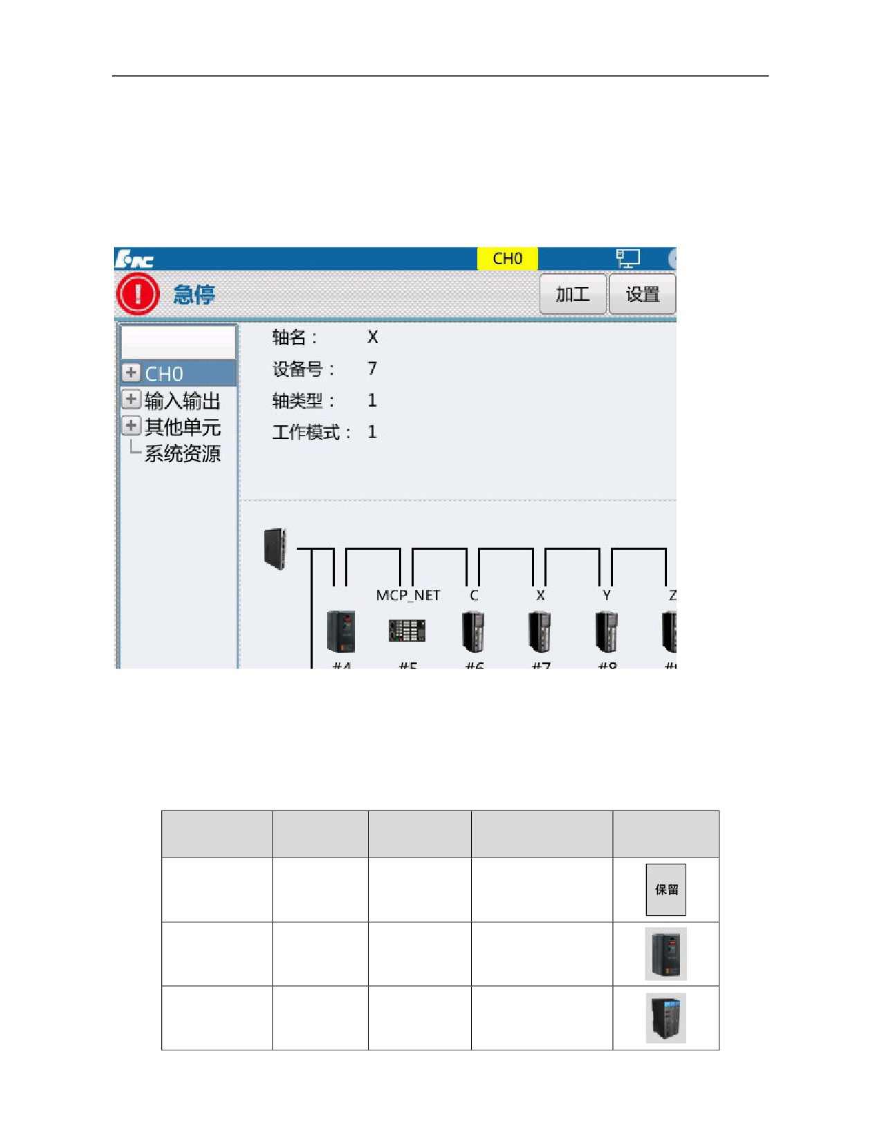
6.2 Verification of Device Parameters
6.2.1 Device Parameters
When the system is powered on for the first time after hardware connection, verify parameters first. If
corresponding devices of displayed parameters are not identified, re-check the hardware connection.
Steps:
Maintain=>F2 device configuration
6.2.2 Axis number and Device Number
The axis number refers to the logical axis number in system and the device number refers to the number of
physical devices on the bus. Different connection of the bus corresponds to different device sequences.
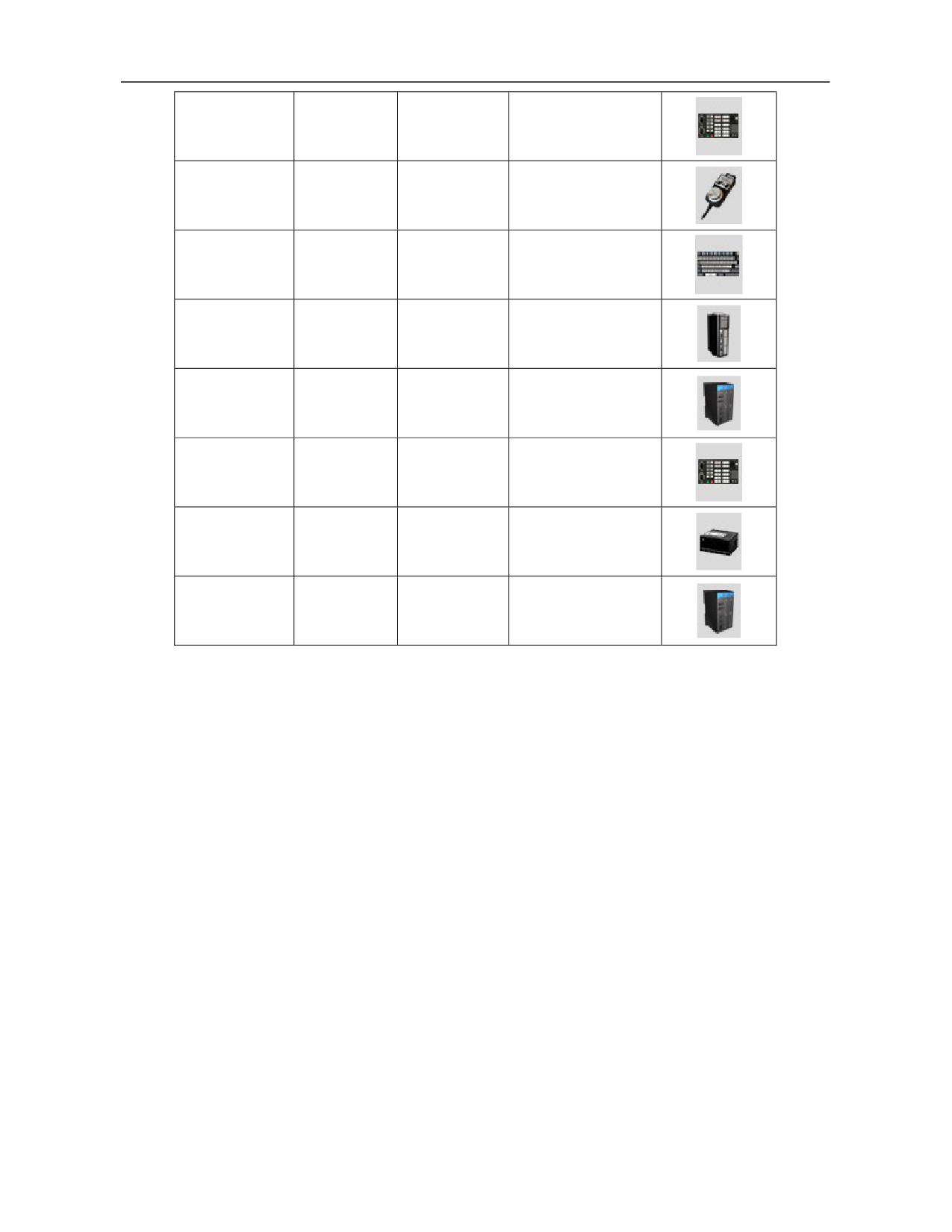
Device types supported by HNC-8 CNC system are shown below
Device type
Device name
Device type
Connection mode
Graphic sign
Reserved
RESERVED
1000
----
Analog spindle
SP
1001
Local
Local IO
IO_LOC
1007
Local
module
60
Local control
MCP_LOC
1008
Local
panel
MPG
MPG
1009
Local
CNC keyboard
NCKB
1010
Local
Servo axis
AX
2002
Bus network
Bus IO module
IO_NET
2007
Bus network
Bus control
MCP_NET
2008
Bus network
panel
Position control
PIDC
2012
Bus network
panel
Encoder
ENC
2013
Bus network
interface board
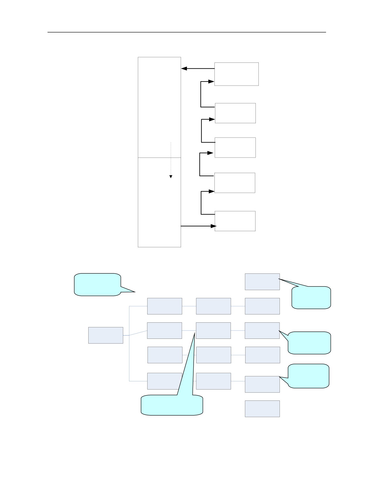
As shown in bus connection diagram of 818B milling system, MCP keyboard unit corresponds to device
number 5, spindle corresponds to device number 6, X axis corresponds to device number 7, Z axis corresponds
to device number 8, and I/O unit corresponds to device number 9.
61
HNC-818B-MU CNC device
NCUC bus
OUT
PORT3
Bus I/O unit
IN
PORT2
NCUC bus
OUT
Z axis drive
PORT1
HSV-160UD
IN
NCUC bus
PORT0
OUTY axis drive
IPC unit
HSV-160UD
IN
Internal wire
NCUC bus
OUTX axis drive
HSV-160UD
IN
MCP unit
NCUC bus
XS6
OUT
NCUC bus
Spindle drive
INHSV-180US
With standard milling machine as an example, the relationship between axis number and device number is
shown in Fig. 3.2.2.
Device #5
Physical axis
MCP_NET
name
Panel device
number
Device #6
S axis
Axis 5
AX
Device#7
X axis
Axis 0
AX
Channel 0
Axis device
number
Device#8
Y axis
Axis 1
AX
IO device
number
Z axis
Axis 2
Device#9
AX
Axis number
Device#10
IO_NET
Fig. 3.2.2 Relationship between axis number and device number
62
6.3 Parameter Setting
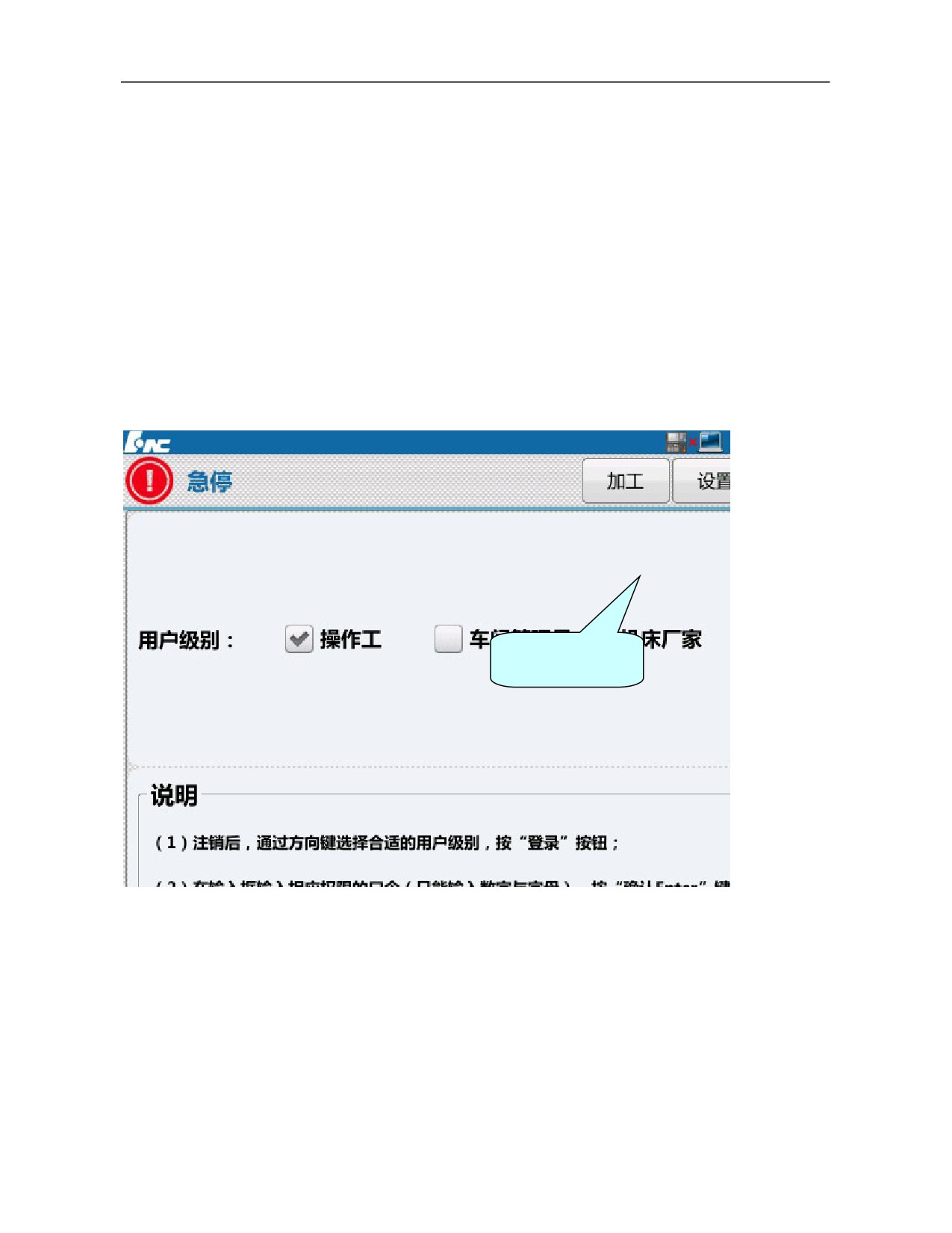
1) Press "Maintain" on the MDI panel→ press F9 "Permission management"→ press F4 "Logout"→select user
level
(the backup is allowed only for workshop manager or above)
→ press F2 “Login”→Enter the
password→ press "Enter" on the MDI panel to confirm (if a correct password is entered, the parameter of the
permission level or the password can be modified; otherwise, the system will give a prompt message "Incorrect
password".) ;
Default permission password:
Operator: Password is not needed
Workshop manager: GOD
Machine tool manufacturer: HOG
CNC manufacturer: HIG
System administrator: HNC8
Enter administrator
password
2) Press F1 “↑” to return→ press F2 "Parameter setting";
3) Select the parameter type by “↑” and “↓” on the MDI panel and press "Enter" on the MDI panel to enter the
suboption;
4) Press → to switch to parameter option window and modify parameter value;
63
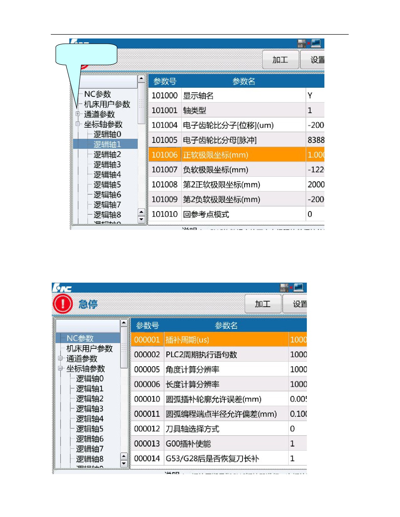
Secondary
extension option
6.4 Parameter Setting of HNC-8 Milling System
6.4.1 NC Parameter Setup
64
1) PARM000012, "tool axis selection mode", the parameter is used to determine the axis for G43/G44 tool
length compensation.
0: Tool length should be compensated on Z axis.
1: Tool length compensation axis is switched through selecting modal G command (G17/G18/G19)
according to coordinate plane and corresponds to Z/Y/X axis respectively.
2) PARM000013, "G00 interpolation enable", the parameter is used to determine whether to enable G00
interpolation motion like G01 interpolation motion.
0: G00 does not execute interpolation motion.
1: G00 executes interpolation motion
3) PARM000014, "Whether to restore tool length compensation automatically after G53/G28 command is
executed", the parameter is used to set whether to automatically restore tool length compensation
function after G53/G28 command is executed.
0: Tool length compensation function cannot be restored automatically after G53/G28 command is
executed. (Recommended)
1: Tool length compensation function is restored automatically after G53/G28 command is executed.
4) PARM000018, "System time display enable", the parameter is used to set whether the HMI of the
CNC system displays current system time.
0:
System time is not displayed
1:
System time is displayed
5) PARM000020, "Automatic display enable of alarm window", the parameter is used to set whether the
CNC system displays the alarm message window automatically.
0:
Alarm message window is not displayed automatically.
1:
If the system gives a new alarm message, the alarm message window will be displayed
automatically.
6) PARM000024, "G code line number display mode", the parameter is used to set the display mode of G
code line number in the HMI of the CNC system.
0: G code line number is not displayed
1: G code line number is displayed only in the editing interface
2: G code line number is displayed only in the program operation interface
3: G code line number is displayed in the editing interface and the program operation interface
7) PARM000025, "Display in metric/inch".
0: Display in inch, the HMI of the CNC system displays in inch.
1: Display in metric, the HMI of the CNC system displays in metric.
8) PARM000026, "Decimal places of positional value", the parameter is used to set the decimal places of
positional value in the HMI of the CNC system, including machine tool coordinates, workpiece coordinates and
remaining feed, etc.
9) PARM000027, "Decimal places of speed value", the parameter is used to set the decimal places displayed
of speed value in the HMI of the CNC system, including F feedrate, etc.
10) PARM000028, "Decimal places of rotation speed", the parameter is used to set the decimal places
displayed of rotation speed in the HMI of the CNC system, including spindle speed S, etc.
11) PARM000030, "Screen protection waiting time (min)", the parameter is to set how long the system
enters screen protection state while NC panel is not being operated. When it is set as 0, screen protection
function is not used.
12) PARM000034, "Operation prompt enable". Use binary to indicate whether there is a confirmation
prompt for the corresponding operation.
Bit 0: Rerun.
65
Bit 1: 【Tool compensation】->【Relative actual】
Bit 2: 【Tool compensation】->【Current position】.
When the value of each bit is 0, it means there is no confirmation prompt, and when it is 1, it means there is a
confirmation prompt.
Example:
When bit 0 is set as 0, press system function key [Rerun] and the interface will directly refresh the cursor to the
position of program header;
When bit 0 is set as 1, press system function key [Rerun] and the interface will give a prompt message whether
to execute rerun.
13) PARM000064, "Tool wear accumulation enable", it is to set whether the tool wear value is the input
value or the input value plus original value
0: Input value
1: Input value plus original value
14) PARM000072, "Whether machining time display is closed", the parameter is used to close machining
time display function.
0: Machining time is displayed
1: Machining time is not displayed
15) PARM000102, "Selection of coordinates displayed", the parameter is used to set type of coordinates
displayed in the machining interface.
0: Machine actual
1: Machine command
2: Workpiece actual
3: Workpiece command
4: Remaining feed
5: Relative actual
16) PARM000349, "Selection of trigonometric function, 0: radian; 1: angle".
0: Trigonometric function is calculated by radian
1: Trigonometric function is calculated by angle
17) PARM000356, "Milling machine function type".
0: Drilling-tapping function without breakpoint function
1: Milling function
18) PARM000358, "Clear MDI program while exiting MDI".
0: MDI program is not cleared while exiting MDI
1: MDI program is cleared while exiting MDI
19) PARM000359, "Default permission".
0: The default permission after power on is the workshop manager permission
1: The default permission after power on is the operator permission
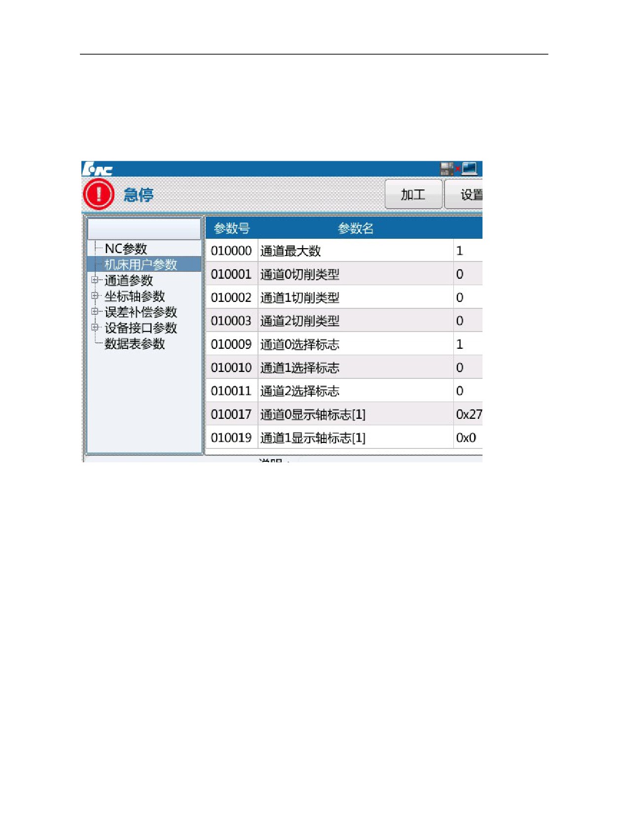
20)PARM000370, "Intelligent function switch".
Set by bit: 0: OFF, 1: ON.
Bit 0: Triathlon health security function
Bit 1: Single sensor thermal error compensation function
Bit 2: Fault data recorder function
Bit 3: None
Bit 4: Feed axis load diagram function
Bit 5: Process parameter evaluation function
Bit 6: Broken tool detection function
66
Bit 7: One-key restore function
Bit 8: Power-on consistency detection function
Bit 9: Enable servo self-diagnosis function
Bit 15: Current/power switching function
6.4.2 Machine User Parameter Setting
1) PARM010000, "Maximum number of channels", the parameter is used to set allowable maximum number
of channels. It is set as 1 by default and 2 when there are two channels.
2) PARM010001, "Cutting type of channel 0", the parameter is used to specify the type of the station.
0:
Milling machine
1:
Lathe system
2:
Turn-mill combination system
3) PARM010009, "Channel 0 selection sign".
Many spindles and drive feed axes can work on a workpiece clamping position, that is, a workpiece
corresponds to more than one channels.
This set of parameters are effective after reset. Bits
0-7 represent selection signs of channels
0-7
respectively. While configuring a channel for a station, the designated position of channel selection sign of
the station should be set as 1 for this station.
4) PARM010017, "Channel 0 display axis sign [1]"
The HMI of the CNC system can display axes in every station selectively based on actual need.
This set of parameters are effective after reset. Bits 0-31 of “Station display axis sign【1】” represent
selections signs of axes 0-31 respectively. When the system supports no more than 64 axes, bits 0-31 of the
extension parameter “Station display axis sign【2】” represent selections signs of axes 32-63 respectively.
While configuring the display axis for a station, the specified bit of display axis sign of the station should
be set as 1 for this station.
67
Note
This set of parameters should be inputted in hexadecimal.
Example
If station 0 includes two channels, there are 10 axes including coordinate axes 0, 2, 4, 5, 6, 7, 8, 10, 13 and
17, but the HMI of the CNC system just needs to display the first 5 axes and Parm010017 "Station 0 axis
display sign 【1】" should be set as 0x75 (hexadecimal input, bits 0, 2, 4, 5 and 6 should be set as 1).
5)
PARM010033, "Customization of load current display axis in channel 0".
The HMI of the CNC system can determine which axis load current is displayed in each station based on
actual needs.
This set of parameters is array type parameters used to set axis number of load current display axes in the
station and the inputted axis number is separated by “.” or “,”.
Note
Array parameters support to 8 data to be input simultaneously and the value ranges from 0 to 127.
Example
Station 1 includes 5 axes including coordinate axes 0, 1, 2, 8 and 9. Axes 0, 1 and 2 are feed axes and axes 8
and 9 are spindles.
If the HMI of the CNC system needs to display load current of feed axes in station 1, Parm010033
"Customization of load current display axis in station 1" should be set as "0, 1, 2".
If the HMI of the CNC system needs to display load current of spindles in station 1, Parm010033
"Customization of load current display axis in station 1" should be set as "8, 9".
If the HMI of the CNC system needs to display load current of all axes in station 1, Parm010033
"Customization of load current display axis in station 1" should be set as "0, 1, 2, 8, 9".
6)
PARM010041, "Whether coordinate axis is displayed dynamically"
The parameter is used to set that the spindle coordinates are not displayed in speed mode and displayed in
position mode.
0: This axis is displayed regardless of whether the spindle is in position mode or speed mode;
1: The spindle coordinates are not displayed in speed mode and displayed in position mode.
Note
The parameter must be validated when there is logical axis number of the spindle in PARM010017/010018
"Station display axis sign".
7) PARM010046, "Radius compensation intervention control"
When radius compensation is intervened, the parameter enables to give an alarm, stop operation, or correct
intervention path automatically. The parameter can avoid intervention and prevent overcut.
0: Intervention alarm.
1: Automatic correction of intervention.
8)
PARM010049, "Maximum allowable number of axes of machine tool"
The parameter is used to set maximum allowable number of logical axes for machine tool. If the parameter
is set as 10, the machine tool is allowed to use axes 0-9, 10 logical axes in total. If other logical axes
(logical axes whose axis number is greater than 9) are configured in the channels, these axes will have no
control command output.
9) PARM010083, "Drilling canned cycle type"
This parameter is to set which system of drilling and tapping canned cycle commands are compatible.
0: HNC8 ssytem
1: SYNTEC
2. MITSUBISHI system
3. FANUC system
68
10) PARM010084, "Peck tapping/deep hole tapping", (specific to canned cycle of other systems than
HCNC system)
The parameter is used to set tapping mode.
0: Peck tapping, the retract amount is set according to G74/G84 feed amount
1: Deep hole tapping. In this mode, the tool retracts to R reference level each time
The value is effective only when there is and feed amount Q in G74/G84 command.
11) PARM010085, "G73 retract amount", (specific to canned cycle of other systems than HCNC system)
The parameter is used to set retract amount of G73 high-speed deep hole drilling cycle.
12) PARM010086, “G83 retract amount”, (specific to canned cycle of other systems than HCNC system)
The parameter is used to set retract amount of G83 high-speed deep hole drilling cycle.
13) PARM010087, "G74/G84 retract amount”, (specific to canned cycle of other systems than HCNC
system)
The parameter is used to set retract amount of G74/G84 tapping cycle and the value is effective only in peck
tapping mode.
14) PARM010088, "tool offset direction after boring spindle orientation stops"
The parameter is used to set offset direction of tool after spindle orientation is completed. (Fine boring
cycle is valid)
0: X+
1: X-
2: Y+
3: Y-
4: Z+
5: Z-
15) PARM010089, "T command control mode"
Set T command tool change mode and tool machining mode in binary.
Bit 0: If it is 0, T command only has the tool selection function and is used for magazine with tool
preselection function, such as manipulator magazine, etc.
If it is
1, T command has tool selection and tool change functions, such as magazine of
drilling-tapping center.
Bit 1: If it is 0, the tool machining mode is disabled; if it is 1, the tool machining mode is enabled.
16) PARM010091, “#500-#999 user macro-variable Enable”
The parameter is used to set whether
#500 to
#999 macro-variables are used as user-defined
macro-variables.
0: #500-#999 are not used as user macro-variables.
1: #500-#999 are used as user macro-variables and consistent with Mitsubishi and FANUC.
17) PARM010098, " Whether G02/G03 converts to G01 when lack of parameters"
The parameter is used to set the processing mode when center or radius is not specified during G02/G03
programming.
0: Alarm prompt
1: Convert to G01
18) PARM010099, "Whether to open magazine management interface for large and small tools"
0: Not open magazine management interface for large and small tools.
1: Open magazine management interface for large and small tools.
19) PARM010104, "New function debugging parameters"
0X1: Enable G68 space rotation function.
0X2: When program is executed automatically, press one-click subprogram call on the MCP panel
69
and call corresponding subprogram after the breakpoint is saved automatically, such as "One-click
tool lifting"
0X4: Enable program operation debugging, run the line in blue to the canned cycle, run the canned
cycle in single block
0X8: Superpose workpiece zero in G91G52
0X0010: Enable multiaxis M instruction: Spindle 0 (M3/4/5) spindle 1 (M13/14/15)
Spindle 1 (M23/23/25) spindle 3 (M33/34/35)
0X0020: Output the interpolation file under Win simulated version
0X0040: Stop interpolation when an interpolation point is produced under Win simulated version until
data is taken away.
0X0080: M99 does not produce the dwell block
0X0100: Synchronization of user-defined variable type
0X0200: Continuously waiting for a response when there is no response of M code synchronization
0X0400: When it is set as 1, return to G00 speed for execution in any line mode; otherwise return to
G01+040030 speed for execution
0X0800: Set the default modal of the first group of G codes (set OX0800 initial modal as G00 and
OX00×× initial modal as G01)
20) PARM010110, "Internal inhibition mask of machine tool protection area"
See special function application description.
21) PARM010111, "External inhibition mask of machine tool protection area"
See special function application description.
22) PARM010165, "Delay time of reference point return (ms)"
The parameter is used to set lag time from finding the Z pulse to the completion of reference point return in
the process of machine tool feed axis returning to the reference point.
23) PARM010166, "Maximum time of exact stop check (ms)"
The parameter is used to set maximum time of detecting positional tolerance of coordinate axis after rapid
traverse positioning (G00). The parameter is validated only when coordinate axis parameter PARM10X060
"Positional tolerance" is not 0.
24) PARM010169, "Enable G64 exact stop check at corner"
The parameter is used to set whether to stop at the corner for the exact stop check in G64. When the
parameter is set as 1, the CNC system will enable the exact stop check function under G64 mode.
Note:
Under G64 modal, if feed length of two straight lines is ≤5mm and vector angle is ≤36。, the CNC system
will adopt arc transition automatically and will not be controlled by the parameter.
25) PRAM010170, "M code corresponding to G1007"
The parameter is used to set corresponding M code, through which user-defined macro program is called.
6.4.3 Channel Parameter Setting
1) RARM040000, "Channel name"
The parameter is used to set channel name. E.g.: Set name of channel 0 as CH0 and name of channel 1 as
CH1. The status bar of the HMI of the CNC system can display name of current channel. The channel name
displayed in the status bar is changed as the channel is switched.
2) PARM040001, "Coordinate axis number of X axis"
The parameter is used to configure X axis number in current channel, realizing mapping between feed axis
and logical axis of channel.
70
0-127: Specify the feed axis number in current channel.
-1: If the feed axis in current channel is not mapped to logical axis, it is an invalid axis.
-2: The feed axis in current channel is reserved for C/S axis switching, and after switching the axis type is the
rotary axis in position mode.
-3: Feed axis in current channel is reserved for C/S axis switching, and after switching the axis type is the
linear axis in position mode.
3) PARM040010, "Axis number of spindle 0"
The parameter is used to set the axis number of spindle 0 in current channel, realizing mapping between
spindle and logical axis in channel.
0-127: Specify spindle number in current channel.
-1: If the spindle in current channel is not mapped to logical axis, it is an invalid axis.
4) RARM040014, "Programming name of X axis"
If CNC is configured with multiple channels, in order to distinguish from axes in each channel during
programming, the system supports the user-defined programming name of coordinate axis. This group of
parameters is used to set programming name of X axis in current channel. The default value is the nine
coordinate axis names based on Cartesian coordinate system in each channel (X/Y/Z/A/B/C/U/V/W).
5) PARM040023, "Programming name of spindle 0"
Each channel of HNC-8 CNC system supports no more than 4 spindles. In order to distinguish from spindles
during programming, the system allows user-defined spindle names in different channels.
6) PARM040027, "Spindle speed display mode"
The parameter takes effect after reset, which is used to set the spindle speed display mode in channels. Bits
0-3 correspond to speed display mode of spindles 0-3. When it is 1, the command speed is displayed. When it
is 0, the actual speed is displayed.
7) PARM040028, "Display number of spindle"
The parameter is used to set logical axis number of spindle in current channel. Set as many logical axis
numbers of spindle as there are spindles in the current channel. If this parameter is not set, the spindle speed
cannot be displayed.
Note
Whereas there is no “,” on the system panel, logical axis number of spindle is differentiated by “.”.
8) PARM040029, "Maximum deceleration time of emergency stop (ms)"
The parameter is used to handle the time that the command speed of coordinate axes reduces to zero when the
system is in emergency stop.
9) PARM040030, "Default feedrate of channel (mm/min)"
When the program in current channel is not specified with the feedrate, CNC will execute the program using
the specified default feedrate.
10) PARM040031, "Feedrate of dryrun (mm/min)"
When CNC switches to dryrun mode, the machine tool will execute the program using this set feedrate .
11) PARM040037, "Acceleration/deceleration time coefficient in hand wheel"
The parameter is used to set the movement acceleration by the handwheel. Taking the corresponding axis
parameter "Rapid traverse acceleration and deceleration time constant" as the reference, the acceleration
and deceleration time in handwheel is converted by the "acceleration and deceleration time constant
coefficient in handwheel", and then the handwheel acceleration is changed. The conversion formula is as
follows:
Converted value of acceleration and deceleration time in handwheel = acceleration and deceleration time
constant in rapid traverse * acceleration and deceleration time constant coefficient in handwheel
12) PARM040038, "Acceleration/deceleration jerk time coefficient in handwheel"
71
The parameter is used to set the jerk of handwheel. Taking the corresponding axis parameter "Acceleration
and deceleration time constant in rapid traverse" as the reference, the acceleration and deceleration jerk time
in handwheel is converted by the "acceleration and deceleration jerk time constant coefficient in
handwheel", and then the handwheel jerk is changed. The conversion formula is as follows:
Converted value of acceleration and deceleration jerk time in handwheel = Acceleration and deceleration jerk
time constant in rapid traverse * Acceleration and deceleration jerk time constant coefficient in handwheel
13) PARM040050, "Maximum magnification for feedrate override"
The parameter is used to limit the maximum magnification of feedrate override.
E.g.
When the feedrate override button of the panel is set to the maximum 200%, the parameter needs to be set
as 2.
14) PARM040113, "Any line mode selection"
The parameter is used to select the execution mode of any line command.
0: Non-scanning mode: commands before the target line will not produce a modal effect.
1: Scanning, return without Z axis: commands before the target line will produce a modal effect, but Z
axis motion command modal is not inherited.
2: Scanning, return with Z axis;
Note
When the target line which executes any line command is the circular interpolation commands, the system
will report circular interpolation parameter error, unless current coordinates coincide with the starting point
of circular interpolation.
15) PARM040114, "Axis in position sequence in any line"
The parameter is used to set sequence of axis motion. Parameter is of numeric type and values are
XYZABCUVW from low to high. 0 means no axis configuration.
E.g.
For milling system, 040114=211 means X/Y axis moves to the right position and then Z axis starts to move.
16)PARM040130, "Tool life management mode"
The parameter is used to set tool life management mode.
0: Disable tool life function.
1: Enable tool life function, and grouping is not supported.
2: Enable tool life function, grouping is supported, T command specifies tool group number.
3: Enable tool life function, grouping is supported, T command specifies tool number. (Just for milling
machine)
6.4.4 Coordinate Axis Parameter Setting
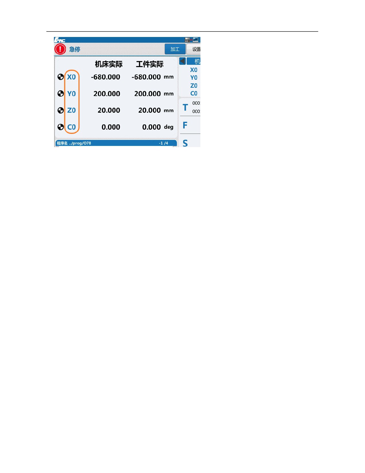
1) PARM100000, "Display axis name"
The parameter is used to set the displayed name of specified axis on the interface.
For multichannel CNC, in order to distinguish from address words in the program of different channels, and
the name consists of a letter and a digit; otherwise, axis name will be displayed incorrectly. Axis name is
often defined such as X0 and X1.
If Parm100000 is set as X0, it will be displayed on the interface as follows.
Figure
72
Note
The parameter is different from the channel parameters Parm040015-040023 "Programming name of
coordinate axis". The former is used for the display on the interface only and the latter is used for
programming. Both may be different, but they' are recommended to be consistent.
The following characters cannot be used to set axis name: D, F, H, M, EQ, LT, GT, GE, LE and PI.
2) PARM100001, "Axis type"
All physical axes of machine tool are useful and this parameter is used to configure the axis type.
0: Not configured, default value.
1: Linear axis.
2: Swing axis, the coordinate value of displayed angle is not limited.
3: Rotary axis, the coordinate value of displayed angle must be within the specified range and the it will
be displayed modulo when the actual coordinates exceed the value.
9: When the traverse axis is used as a spindle, the drive is the feed axis drive.
10: Spindle.
3) PARM100004, "Numerator of electronic gear ratio [displacement] (um)"
For linear axis, this parameter is used to set the movement distance of machine tool per revolution of motor.
For rotary axis, this parameter is used to set the movement angle of machine tool per revolution of motor.
4) PARM100005, "Denominator of electronic gear ratio [pulse]"
The parameter is used to set the number of pulse commands per revolution of motor.
Example
For servomotor of 131072 ppr encoder, lead of guide screw is 6mm and electronic gear ratio is 2/3.
The machine tool moves 6mm* 2/3 = 4mm, namely 4000um, per revolution of motor, then:
4000/131072
Parm100004 "Numerator of electronic gear ratio" is set as 4000 and Parm100005 "Denominator of electronic
gear ratio" is set as 131072.
5) PARM100006, "Positive software limit coordinate (mm)"
Limit software protection position in the positive direction stipulated by CNC software. The moving range of
traverse axis or rotary axis cannot exceed the limit.
Figure
73
M
+Limit
Home -Limit
M
Negative
Positive direction of axis
+999999
direction of axis
-999999
Note
The parameter is valid only after the machine tool returns to the reference point.
Set an appropriate parameter value according to the mechanical travel of machine tool and the size of
workpiece. If the setting is too small, the software limit alarm may be issued repeatedly during machining.
When the third bit of G((80*logical axis number)+1) is 1, the positive software limit coordinate is invalid
and the second positive software limit coordinate is valid.
Example
The first software limit of logical axis 0 is valid and the second positive software limit coordinates of logical
axes 1 and 2 are valid. G1.2 is set as 0 and G81.2 and G161.2 are set as 1 in the ladder diagram.
6) PARM100007, "Negative software limit coordinate (mm)"
Limit software protection position in the negative direction stipulated by CNC software. The moving range
of traverse axis or rotary axis cannot exceed the limit.
Figure
M
+Limit
Home -Limit
M
Negative dire ction
Positive direction of axis
+999999
of axis
-999999
Note
The parameter is valid only after the machine tool returns to the reference point.
Set an appropriate parameter value according to the mechanical travel of machine tool and the size of
workpiece. If it is too small, the software limit alarm may be issued repeatedly during machining.
When the third bit of G((80*logical axis number)+1) is 1, the positive software limit coordinate is invalid and
the second positive software limit coordinate is valid.
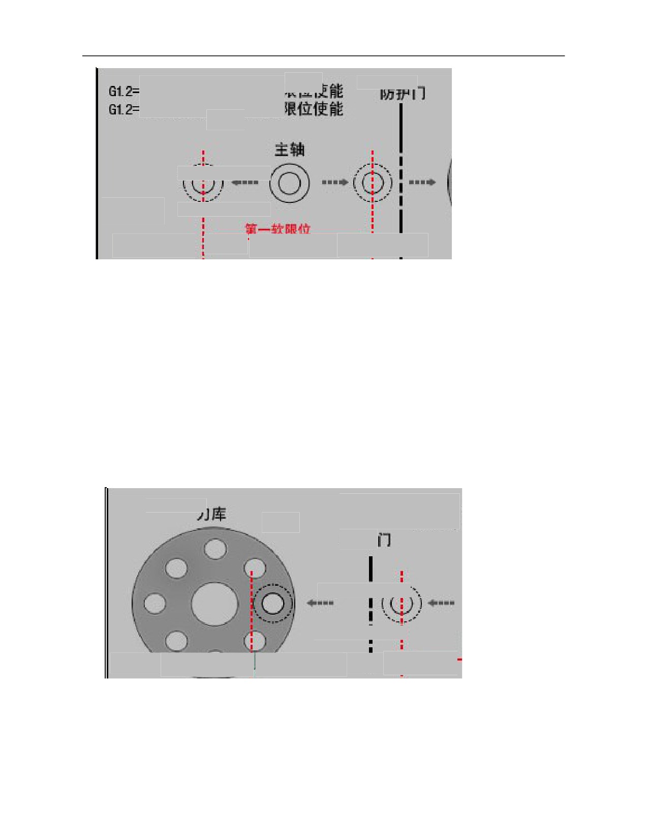
7) PARM100008, "The second positive software limit coordinate (mm)"
Limit software protection position in the positive direction stipulated by CNC software. It takes effect when
the second software limit is enabled. The moving range of traverse axis or rotary axis cannot exceed the
limit.
Figure
74
Protective door is closed. The first software limit is
Protective
Magazine
enabled
door
Protective door is opened. The second software limit is
enabled
Spindle
First software limit
Positive direction
Second software limit
of X axis
X positive software
Zero point First X negative software
Second X negative
limit coordinates
limit coordinates
software limit coordinates
Note
The parameter is valid only after the machine tool returns to the reference point.
Set an appropriate parameter value according to the mechanical travel of machine tool and the size of
workpiece. If the setting is too small, the software limit alarm may be given repeatedly during machining.
The first software limit is invalid after the second software limit is enabled. It is determined by G register.
Example
Enable the first positive software limit during normal machining and set G1.2 as 0. For tool change, set G1.2
as 1 in the ladder diagram, and the first positive software limit is disabled and the second positive software
limit is enabled. After the tool change is completed, set G1.2 as 0 in the ladder diagram and enable the first
software limit.
8) PARM100009, "The second negative software limit coordinate (mm)"
Limit software protection position in the negative direction stipulated by CNC software. The moving range
of traverse axis or rotary axis cannot exceed the limit.
Figure
Protective door is closed. The first soft limit is
Magazine tool
enabled
Protective door is opened. The second soft
Protective
limit is enabled
door
Spindle
First software limit
Second software limit
Positive directio
Second X negative
Second X negative Zero point X positive software
of X axis
software limit coordinates software limit coordinates
limit coordinates
Note
The parameter is valid only after the machine tool returns to the reference point.
Set an appropriate parameter value according to the mechanical travel of machine tool and the size of
workpiece. If it is too small, the software limit alarm may be issued repeatedly during machining.
The first software limit is invalid after the second software limit is enabled. It is determined by G register.
75
Example
Enable the first negative software limit during normal machining and set G1.2 as 0. For tool change, set G1.2
as 1 in the ladder diagram, and the first negative software limit is disabled and the second negative software
limit is enabled. After tool change is completed, set G1.2 as 0 in the ladder diagram to enable the first
software limit.
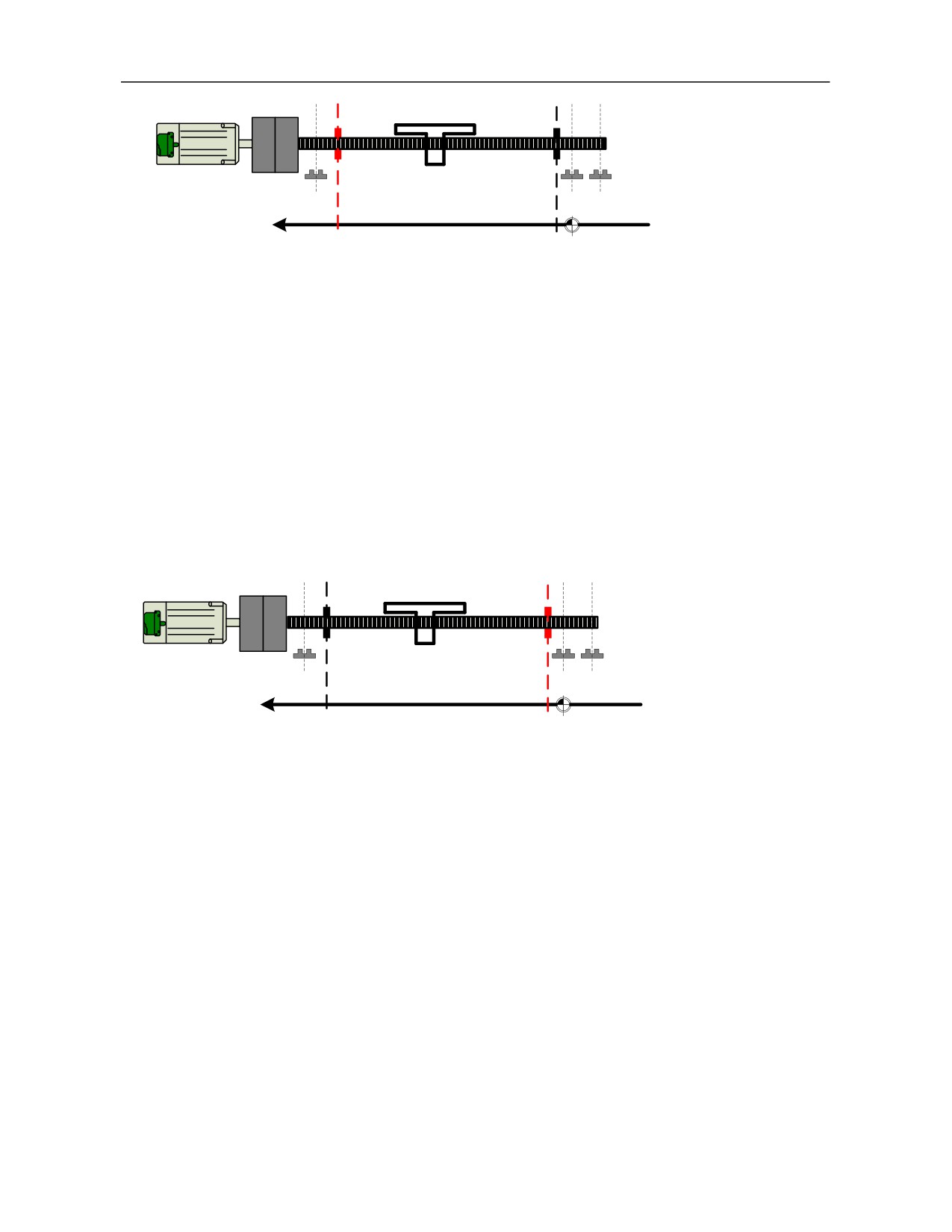
9) PARM100010, "Reference point return mode"
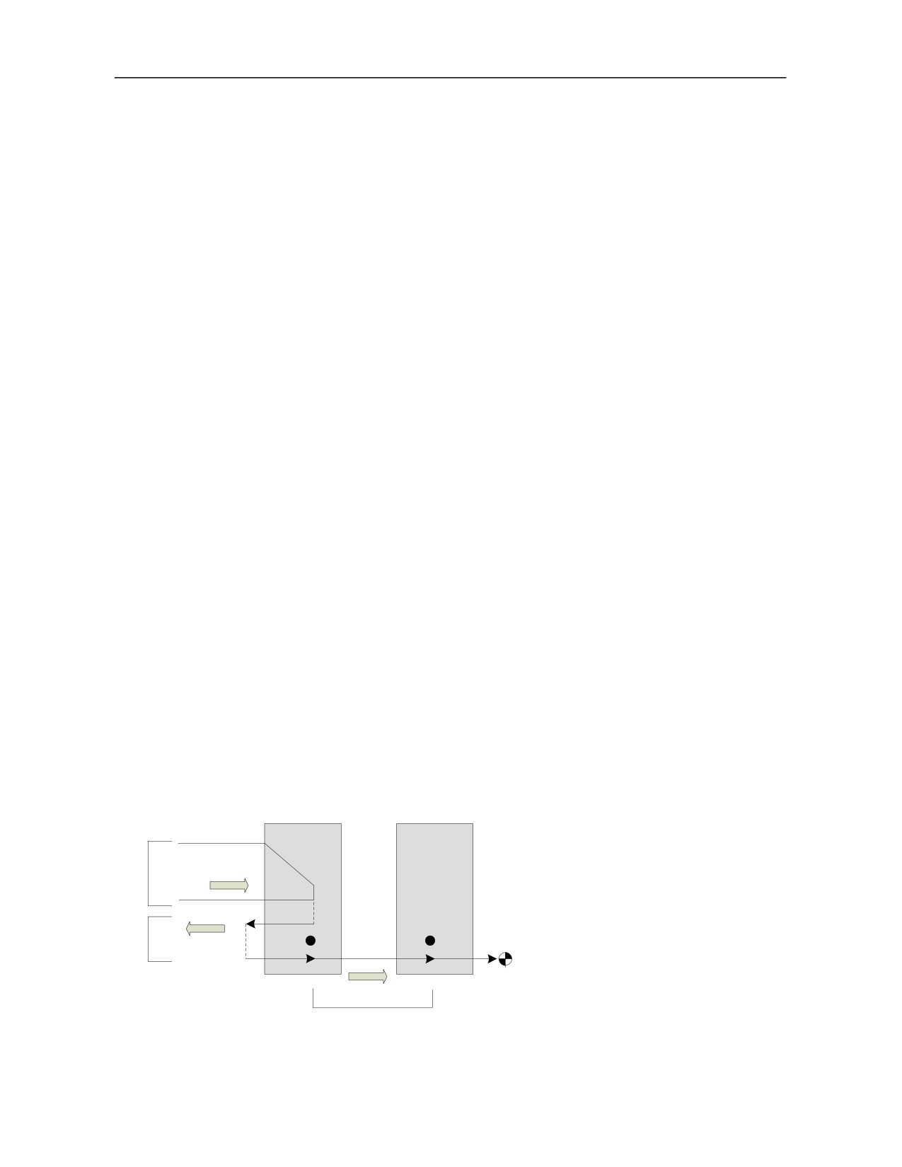
HNC-8 CNC system has the following reference point return modes:
0: Absolute coding
When the encoder is powered on, the position value can be obtained immediately and offered to the CNC
system. When the CNC system is powered off, the current position of machine tool is not lost, so the system
need not move axes of the machine tool to locate the reference point and the machine tool can run
immediately.
2: + -
Move to the reference point switch from the current position at high speed of reference point return in the
direction of reference point return. Press the reference point switch and move in the opposite direction at low
speed of reference point return until the system detects the first Z pulse position. Continue moving a certain
distance based on the set value of Parm100013“Offset after reference point return” to complete the reference
point return.
3: + - +
Move to the reference point switch from the current position at high speed of reference point return in the
direction of reference point return. Press the reference point switch and move in the opposite direction to
leave the reference point switch. Search Z pulse in the opposite direction at low speed of reference point
return until the system detects the first Z pulse position. Continue moving a certain distance based on the set
value of Parm100013“Offset after reference point return” to complete the reference point return.
4: Distance-coded reference point return 1
When CNC is equipped with distance-coded grating ruler, the machine tool just needs to move a short
distance to locate the reference point and build a coordinate system. It is set to 4 when the grating ruler
feedback and the reference point return direction are the same.
5: Distance-coded reference point return 2
When CNC is equipped with distance-coded grating ruler, the machine tool just needs to move a short
distance to locate the reference point and build a coordinate system. It is set to 5 when grating ruler feedback
and reference point direction are opposite.
Return to the reference point in two directions
Reference poi nt
Z phas e pulse
switch
Search direction
1
2
Negative positi oning
R
Research Z phase pul se
3
76
+- Return to the reference point
Reference poi nt
switch
Z phase pulse
1 Search direction
R
2
Search Z phase pulse
Note
The reference point return mode is determined by type of feedback component adopted by axes of machine
tools. After machine tool is started, build a coordinate system and the program can run automatically. If an
axis uses incremental displacement measurement feedback system, the axis must return to the reference point
first.
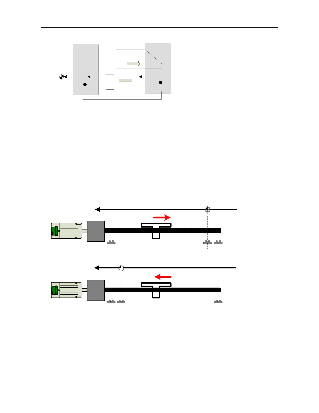
10) PARM100011, "reference point return direction"
The parameter is used to set the initial moving direction of coordinate axis at the time of reference point
return.
1: Positive direction
-1: Negative direction
0: Reference point direction is not specified (for distance-coded reference point return)
M
Return to the reference
Negative
Pos itive direction of axi s
point i n the negative
direction of axis
direction
M
+Limit
Home -Limit
M
Negative
Pos itive direction of axi s
Return to the reference point
direction of axis
in the posit ive di rect ion
M
+Limit Home
-Limit
Note
The parameter setting is related to the position the machine reference point switch is installed. If an
incorrect reference point direction is set, the reference point return failure will occur.
While using this reference point return mode, the "working mode" of axis in device parameters must be set
as 1 (incremental encoder type).
Whereas the distance-coded reference point return direction is controlled by PLC, this parameter must be
set as 0 when the distance-coded reference point return is adopted.
11) PARM100012, "Encoder feedback offset (mm)"
77
The parameter is mainly for absolute encoder motor. Whereas the absolute encoder will feed back a random
position value when it is used for the first time, users can fill the value in the parameter and the current
position is the origin of the machine coordinate system.
Note
If coordinates of machine tool are not cleared after current coordinate position is filled out, after gear ratio
of axis is set, press Alt+left/right key in the program interface to adjust the top right corner of the interface
to "Motor position" and record motor position of each axis,
Encoder feedback offset= motor position/pulse count per axis revolution * lead of guide screw (mm).
Example
e.g.: Motor position is 266700000, pulse count is 131072 per axis revolution and lead of guide screw is
4mm. Set the position as the zero point of X axis of current machine tool, then the encoder feedback offset
=266700000/131072*4=8139.0381.
Note
The system can calculate the offset value automatically. Press "Auto offset" to set zero point of all
axes.
12) PARM100021, "Coordinate value of the second reference point (mm)"
The system can specify no more than 5 reference points under the machine coordinate system. The
parameter is used to set the coordinate value of the second reference point.
This reference point can be returned with the command G30 P2.
The second reference
point R
Note
When the actual position of machine tool is at the coordinates of the second reference point, F (logical axis
number * 80).8 is 1. During tool change, this register can be used to determine whether the axis is at the
tool change point.
Example
Axes 0, 1 and 2 move to the second reference point respectively. Determine whether F0.8, F80.8 and
F160.8 are 1 in the ladder diagram. If they are 1, it means that the machine tool is at the second reference
point.
13) PARM100025, "Deviation of reference point range (mm)"
78
The parameter is used to determine the error range that whether the axis is at the reference point.
When positional deviation between actual position of machine tool and reference position is less than the
parameter, it can be determined that the axis is at the reference point and reference point position mark in
state sign field of axis is set to 1.
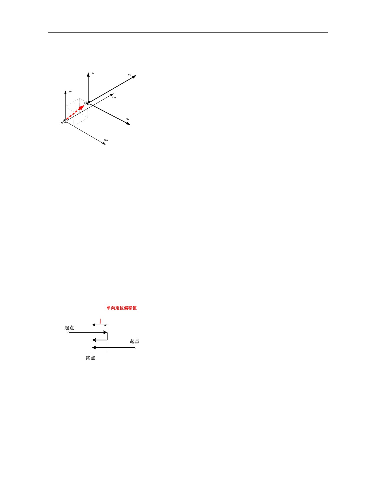
14) PARM100030, "Unidirectional positional (G60) offset value (mm)"
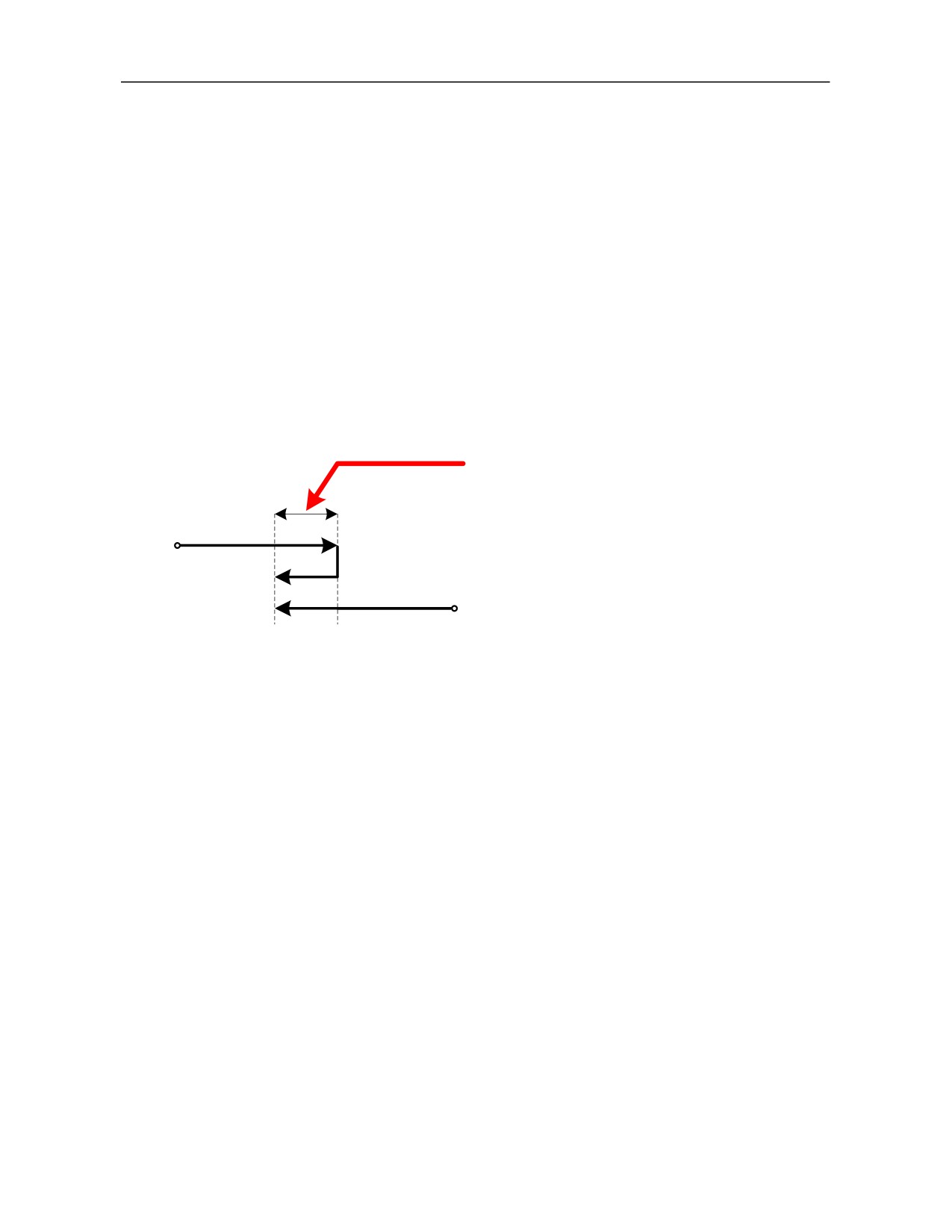
In order to eliminate the effect of the screw nut pair backlash during positioning, the coordinate axis can be
specified to be positioned from a fixed direction to the target position. That is, whether the final position is
in the positive direction or the negative direction of the initial position, the direction of approaching the
final position is fixed. When the parameter is positive, it means that G60 is positive positioning. When it is
negative, it means that G60 is negative positioning. When G60 positioning direction is opposite to the
moving direction of command, the axis will continue moving a certain distance after reaching the
destination and then move oppositely to the destination in the G60 positioning direction. The parameter is
used to designate the moving distance and G60 positioning direction.
Figure
Unidirectional positioning offset value
Start point
End point
Start point
Note
It should be noted that the set value of the parameter should be greater than backlash of corresponding axis.
15) PARM100031, "Converted radius of rotary axis (mm)"
The parameter is used to set radius of current rotary axis and it is set to convert angular speed of rotary axis
into linear speed.
Maximum speed of rotary axis (mm/min)=Maximum rotation speed of axis*2*PI*Converted radius of
rotary axis.
Note
Whereas the rotary axis rotates for 360o in a revolution, linear speed is 360mm/min if the rotary axis rotates
for a revolution within a minute.
360=2∏R
R=360/2 /∏=57.3
Thus, converted radius of rotary axis should be 57.3.
Example
If maximum speed of rotary axis is 3000r/min, converted radius of rotary axis is 57.3mm.
Maximum speed of current axis=3000*2*3.1415*57.3=1079532mm/min.
16) PARM100032, "Slow speed jog speed (mm/min)"
The parameter is used to set slow speed jog speed of axis in jog mode (JOG).
Figure
79
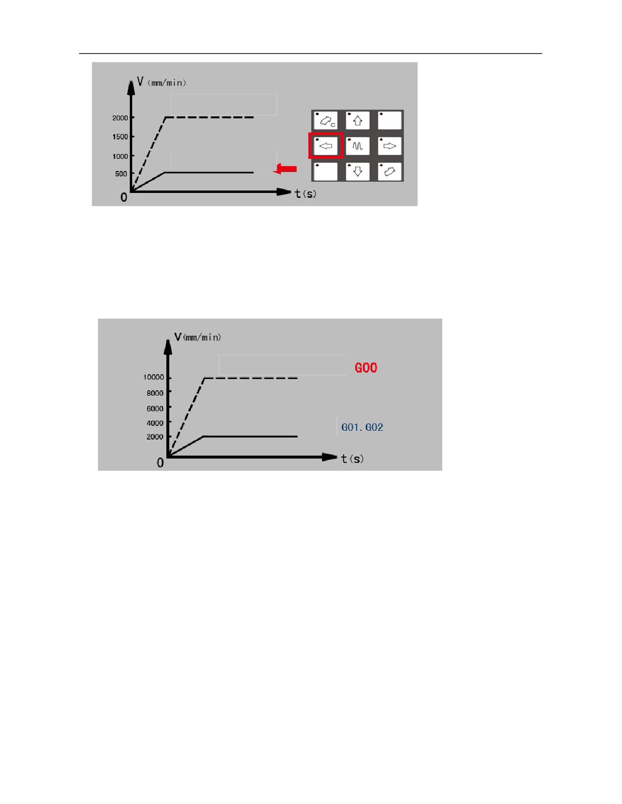
High speed jog speed
Slow speed jog speed
Note
While jogging axis under jog mode (JOG), movement speed of axis is affected by feed rate override.
Rotary axis is affected by its converted radius.
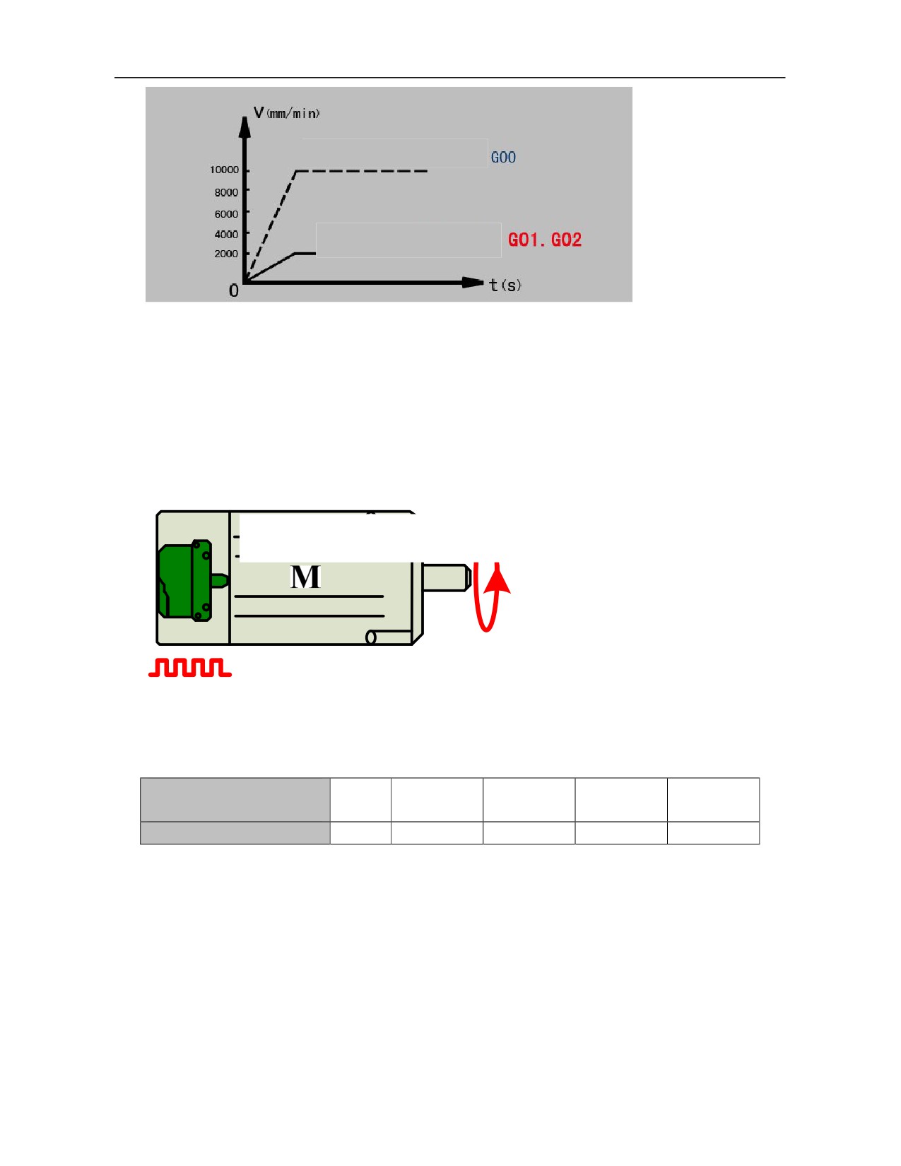
17) PARM100034, "Maximum rapid traverse speed (mm/min)"
The parameter is used to set maximum speed of rapid traverse positioning (G00) of axis.
Maximum speed of rotary axis = Maximum speed of axis *2*PI* Converted radius of rotary axis.
Figure
Rapid traverse speed
Machining speed
Note
Maximum rapid traverse speed must be the maximum value of all speed parameters of an axis. Maximum
rapid travese speed is closely related to the ratio between numerator and denominator of external pulse
equivalent. This parameter must be set reasonably in order to avoid exceeding the motor speed range. e.g.:
If rated speed of motor is 2000rev/min, and the motor is connected to the ball screw whose screw lead is
6mm through a pair of synchronous toothed belts whose transmission ratio is 1:1.5, then:
Maximum rapid traverse speed ≤2000× (1/1.5) ×6=8000mm/min.
Rotary axis is affected by its converted radius.
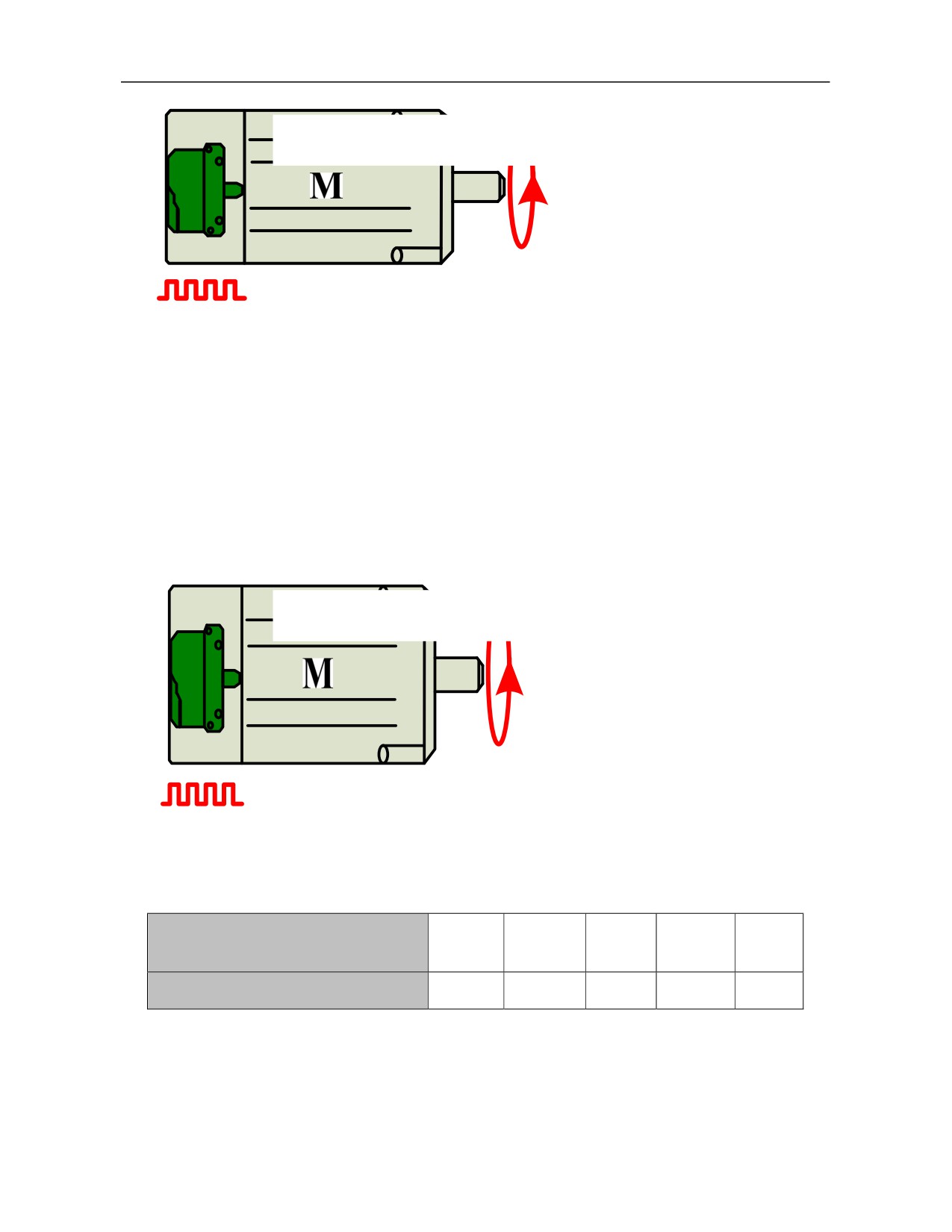
18) PARM100035, "Maximum machining speed (mm/min)"
The parameter is used to set maximum machining speed (G01, G02…) of axis.
Figure
80
Rapid traverse speed
Machining speed
Note
The parameter is related to machining requirements, mechanical transmission and load. Maximum
machining speed must be less than maximum movement speed.
Rotary axis is affected by its converted radius.
19) PARM100036, "Rapid traverse acceleration and deceleration time constant (ms)"
It refers to the time that linear axis speeds up from 0 to 1000mm/min or slows down from 1000mm/min to 0
during rapid traverse (G00). The parameter determines acceleration of axis. The larger this parameter the
smaller acceleration and deceleration.
Figure
T: Rapid traverse acceleration/deceleration
time constant
Note
The parameter is determined by motor rotational inertia, load rotational inertia and drive acceleration
capacity.
Comparison between common rapid traverse acceleration/deceleration time constant and acceleration:
Acceleration/deceleration
2ms
8 ms
16 ms
32 ms
64 ms
Time constant
Acceleration
1g
0.2g
0.1g
0.05g
0.02g
Example
Rapid traverse acceleration/deceleration time constant is set as 4ms, rapid traverse acceleration is figured
out as shown below:
1000mm/60s≈16.667mm/s
16.667/0.004≈4167mm/s2 ≈0.425g (1g=9.8m/s2 )
20) PARM100037, "Rapid traverse acceleration/deceleration jerk time constant (ms)"
This parameter refers to the time that an axis speeds up from 0 to 1m/s2 or slows down from 1m/s2 to 0
during rapid traverse (G00). The parameter determines rapid traverse jerk of axis. The larger the time
constant, the more gently the acceleration changes.
Figure
81
T: Rapid traverse acceleration/deceleration
jerk time constant
Note
The parameter is determined by motor size, drive performance and load size and it is often limited to 8-150.
Example
Suppose rapid traverse acceleration is 0.2g (namely 1.96m/s2) and rapid traverse acceleration/deceleration
jerk time constant is set as 8ms, then the jerkis 1.96/0.008=245m/s3.
21) PARM100038, "Machining acceleration/deceleration time constant (ms)"
This parameter refers to the time that the linear axis speeds up from 0 to 1000mm/min or slows down from
1000mm/min to 0 during machining (G01 and G02, etc.). The parameter determines machining speed of
axis. The larger machining acceleration and deceleration time constant is the smaller acceleration and
deceleration is.
Figure
T: Machining acceleration/deceleration
time constant
Note
The parameter is determined by motor rotational inertia, load rotational inertia and drive acceleration
capacity.
Comparison between common machining acceleration/deceleration time constant and acceleration:
Machining acceleration and deceleration
2ms
8 ms
16 ms
32 ms
64 ms
time constant
Acceleration
1g
0.2g
0.1g
0.05g
0.02g
Example
Machining acceleration/deceleration time constant is set as 6ms, machining acceleration is figured out as
shown below:
1000mm/60s≈16.667mm/s
16.667/0.006≈2778mm/s2≈0.283g (1g=9.8m/s2 )
82
22) PARM100039, "Machining acceleration and deceleration jerk time constant (ms)"
"Machining acceleration and deceleration jerk time constant refers to the time that an axis speeds up from
0 to 1m/s2 or slows down from 1m/s2 to 0 during machining (G01 and G02, etc.). This parameter
determines machining jerk of axis. The larger the time constant is the more gently the acceleration changes.
Figure
T: Machining acceleration/deceleration
jerk time constant
Note
The parameter is determined by motor size, drive performance and load size and it is often limited to
8-150.
Example
Suppose machining acceleration is 0.05g (namely 0.49m/s2) and machining acceleration/deceleration time
constant is set as 128ms, then the jerk is 0.49/0.128≈3.8m/s3.
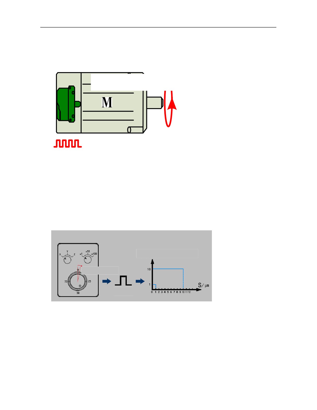
23) PARM100043, "Pulse resolution of MPG (um)"
The parameter is used to set the distance of a pulse axis as the MPG rotates a graduation when the MPG
override is
×1.
Figure
MPG pulse resolution
1 graduation
1 pulse
Note
When Parm010001“Station machine type” is set
1
(lathe) and Parm040032 "Diameter/Radius
programming” is set as 1, the MPG pulse resolution corresponding to X axis should be set as 0.5.
Example
e.g.: When in the MPG mode the lathe X axis needs to move 0.0001mm as the MPG rotates one graduation,
this parameter should be set as 0.05. While the lathe Z axis needs to move 0.0001mm as the MPG rotates
one graduation, the parameter should be set as 0.1.
24) PARM100045, MPG Buffer Periods
Within the number of MPG buffer periods, the machine tool moves at low speed. When beyond the number
83
of MPG buffer periods, the machine speeds up.
25) PARM100047, MPG Maximum Speed
The parameter is used for the situation that uneven speed of MPG occurs during th.
26) PARM100048, Overspeed Alarm Coefficient"
The parameter is used to set the coefficient value when the system gives an alarm against overspeed of axis,
namely when actual speed of axis exceeds the product of command speed of system and axis, the system
will give an alarm against overspeed of axis.
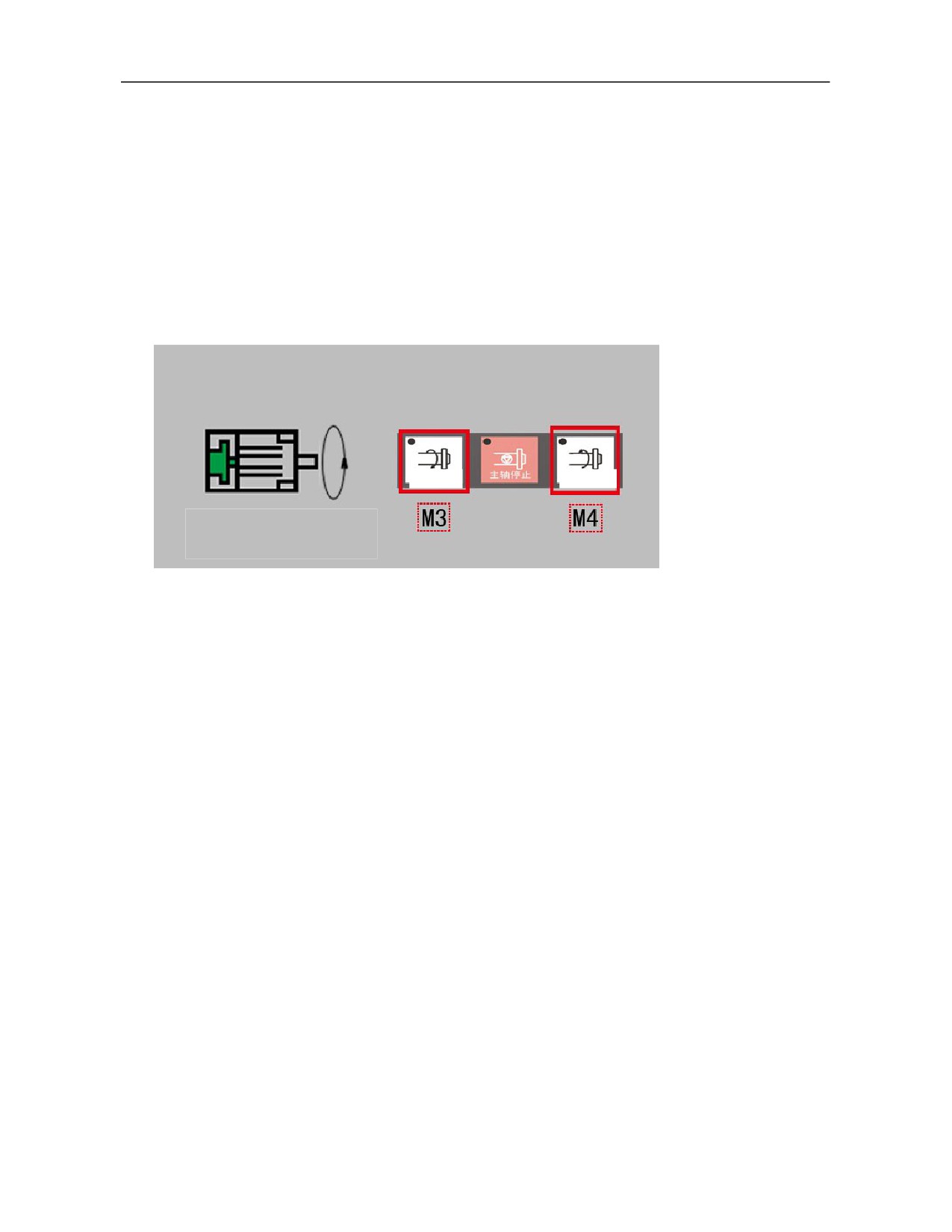
27) PARM100050, Default S Rotation Speed (r/min)"
When the spindle rotation M03 or M04 is specified, if the rotation speed S is not specified, the default
rotation speed S set by this parameter is adopted.
Figure
Spindle CW
Spindle CCW
Default S rotation speed
Note
If M3 command is followed by the spindle speed and the new M3 is not followed by the spindle speed, the
default rotation speed S is valid only when spindle speed is not specified.
Example
When 1000 is set, and M3 or rotating spindle CW is executed after power-on, the spindle speed is
1000r/min.
28) PARM100052, Allowable Fluctuation Ratio of Spindle Speed
According to machine tool conditions, the parameter is used to detect whether the spindle speed fluctuates
normally within a certain range.
Fluctuation range of actual spindle speed= ± current command spindle speed * allowable fluctuation ratio
of spindle speed.
29) PARM10006, "Positioning tolerance"
The parameter is used to set allowable exact stop error of rapid traverse positioning (G00) of coordinate
axis.
0: There is no positioning tolerance limit for the current axis
>0: If machine coordinates of current axis still exceed the set value of positioning tolerance after
reaching Parm 010166 "Maximum time for exact stop check", the system will give an alarm.
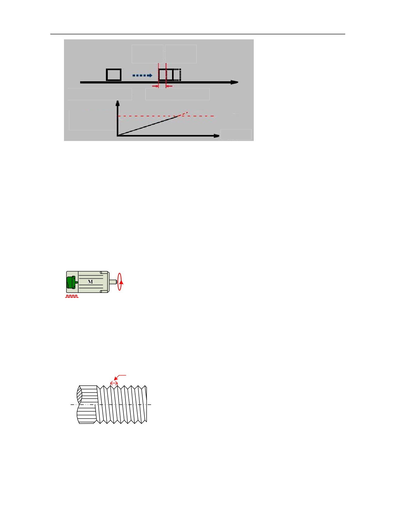
30) PARM100061, "Maximum tracking error (mm)"
Allowable maximum error when the coordinate axis moves. When Parm100090 "Encoder working mode"
is set as 0, the tracking error is calculated by servo drive and the CNC system acquires tracking error
directly from the servo drive. When it is set as 1, the tracking error is calculated by the system.
Figure
84
Actual
Command
position position
Tracking error value
Tracking error
Maximum
tracking error
Position S
Note
When the coordinate axis moves, CNC will monitor whether tracking error of axis is within the parameter
setup range in real time. Tracking error is often limited to 0.1-1. If the parameter is too small, the system
may easily shut down due to large positioning error. If the parameter is too large, machining accuracy will
be affected. Generally, the larger machine tool is the larger the value is; the worse mechanical drive and
accuracy of machine tool is the larger the value is; the larger the movement speed of machine tool is the
larger the value is.
31) PARM100067, "Pulse count per revolution of axis (pulse)"
The parameter refers to pulse count received by CNC device when the current axis rotates one revolution,
namely, the number of pulses fed back to CNC device when the servo drive or the servomotor controls the
axis to rotate one revolution. Generally, it is the actual pulse count of position encoder of servomotor. If
there is reduction ratio, it is the product of pulse count of motor per revolution and reduction ratio.
Figure
Example
If pulse count of motor per revolution is 131072 and reduction ratio is 40:1, the parameter is 131072*40,
namely 5242880.
32) PARM100068, "Guide screw lead"
The axial distance between corresponding points of two adjacent teeth on the same helical line.
Figure
Lead
33) PARM100073, "Speed display coefficient of rotary axis"
When the parameter is set as 1.0, speed display unit of rotary axis is "°/min".
For rotary axis requiring high rotation speed, speed F displayed in "°/min" is often very large. In this case,
speed display of rotary axis can be adjusted through this parameter setting. If the parameter is set as 0.0028,
speed F display unit of rotary axis will be converted into "rev/min".
85
34)
PARM100082, "Short path mode of rotary axis"
0: Common mode, CW rotation when the command coordinate value is greater than current position
and CCW rotation when it is smaller than current position.
1: Short path rotation mode.
2: Unidirectional rotation CW mode.
3: Unidirectional rotation CCW mode.
To use this function, PARM100001 "Axis type" must be set as 3, namely the rotary axis type, and
"Feedback position cycle enable" in device parameters must be set as 1. While specifying rotary axis in
incremental mode correspondingly, the moving direction of rotary axis is the symbol of increment and the
movement amount is the command value.
35)
PARM100090, "Encoder working mode"
The parameter is used to set usage mode of specified axis motor encoder by bit.
Bit 8: Tracking error monitoring of feed axis
0: Tracking error is calculated by the servo drive and the CNC system acquires tracking error directly
from the servo drive.
1: Tracking error is calculated by the CNC system based on the encoder feedback.
If the servo drive does not upload tracking error and the parameter is set as 0, the CNC system will not
display or the monitor tracking error of feed axis.
Bit 12: Whether to enable counter rollover of absolute encoder
0: When it is disabled, pulse count of absolute encoder is valid only within a single count range.
1: When it is enabled, effectively increase count range of encoder through recording rollover times of
absolute encoder.
For linear axis of extra-long travel or linear axis/rotary axis with large reduction ratio, if absolute encoder
is used, the rollover count function of absolute encoder must be enabled in order to avoid loss of machine
tool coordinates arising from power-off after the axis runs long in the same direction.
Note
The parameter is inputted and displayed in hexadecimal.
Example
Existing rotary axis A (logical axis 3, device 10) adopts single-turn 17-digit and multi-turn 12-digit
absolute encoder and has reduction ratio of 180:1. In order to avoid loss of machine tool coordinates
arising from power-off after the axis runs long in the same direction, parameter setting is shown below:
Coordinate axis parameter PARM103090 “Encoder working mode” is set as 0x1100;
Coordinate axis parameter PARM103094 "Encoder counting digits" is set as 29;
Coordinate axis parameter PARM103067 "Pulse count per revolution of axis (pulse)" is set as 23592960
(131078*180);
Device interface parameter PARM510014 “Feedback position cycle mode" is set as 1;
Device interface parameter PARM510015 ““Feedback position cycle pulse count" is set as 23592960;
36)
PARM100094, "Encoder counting digits"
The parameter is set according to the number of counting digits (single-turn + multi-turn digits) of absolute
rotary pulse encoder and it can be set as 0 for incremental rotary pulse encoder and linear grating ruler and
other types of encoders.
Suppose number of digits of absolute rotary pulse encoder is N, the counting range of encoder is 0 to 2N-1.
Note
If the counting range of absolute encoder is less than the travel of feed axis, the counter rollover exists
when the axis runs long in the same direction. In this case, the bit 12 of coordinate axis parameter
PARM103090 "Encoder working mode" should be set as 1.
86

Example
A linear feed axis is furnished with absolute rotary pulse encoder and the number of single-cycle digits is
17 (namely pulse count per revolution of encoder is 217=131072) and number of multi-turn digits is 12, the
parameter should be set as 17+12=29.
37)
PARM100130, "Maximum error compensation rate (mm or degree)"
Comprehensive compensation value of current axis can be smoothened via this parameter setting in order
to prevent impact on machine tool arising from abrupt change of compensation value. If the variation of
comprehensive error compensation value of two adjacent interpolation periods is greater than the set value
of the parameter, the system will give a prompt message "error compensation rate reaches the upper limit",
the program will continue running and the variation of comprehensive error compensation value will be
restricted to this maximum value.
38)
PARM100131, "Maximum error compensation value (mm or degree)"
The allowable maximum displacement error of axis can be set by the parameter. If the comprehensive error
compensation value outputted to current axis is greater than the set value of the parameter, the system will
give a prompt message "error compensation value reaches the upper limit", the program will continue
running and the comprehensive error compensation value will be restricted to this maximum value.
39)
PARM100132, "Feed axis feedback deviation (mm)"
To solve sudden jump of absolute motor, set "Feed axis feedback deviation" in coordinate axis parameters.
When this parameter value is 0, the sudden jump of motor position is not monitored after power on. When
position deviation of axis exceeds this deviation value, F[logical axis number *80+68] is set as 1. Users
can decide whether alarm issuing or emergency stop is used according to state of this register point.
40)
PARM100196, "Power-off feedback pulse position tolerance (pulse)"
41)
PARM100197, "Power-off position tolerance (pulse)"
If the parameter is 0, this function is disabled by default. It is valid when any number greater than 0 is set
and the unit is pulse.
The parameter is used when multi-turn position of absolute encoder is memorized by battery power (such
as Tamagawa absolute encoder) and the system gives an alarm when batteries are exhausted and multi-turn
position is lost. The value is related to encoder resolution. If 131072 pulses are fed back when the absolute
encoder rotates one revolution, the parameter value should be 131072.
6.4.5 Error Compensation Parameter Setting
HNC-8 CNC system has over-quadrant sudden jump compensation function, pitch error compensation function,
backlash compensation function, perpendicularity compensation function and thermal error compensation
function with/without temperature sensor. For details, refer to "HNC-8 User Manual Milling System".
6.4.6 Device Interface Parameters
1) Device 0-Device 4
Definition of device 0-device 4 is determined by the value of G2963 in PLC initialization (INIT) module.
Register G2963 (decimal)
Drive description
Note
0
Devices 0-3 are devices reserved by the system
Default configuration
1
Devices 0-4 are imaginary axes and can be allocated to
Configurable
87

system axis.
Imaginary axis and imaginary MCP panel are mixed.
Devices 0-3 are imaginary axes that can be allocated to
system axis and are used during simulation running.
2
Configurable
Device 4 is an imaginary MCP and after it is enabled
the keyboard can be used as MCP. This function can be
used when there is no MCP panel.
Driven by imaginary pulse axis. Devices
0-3 are
4
imaginary axes and this function is used when pulse
Configurable
axis card is used.
2)
Bus control panel
a. MCP type
The parameter is used to specify type of bus control panel.
0: Invalid
1: HNC-8A type control panel
2: HNC-8B type control panel
3: HNC-8C type control panel
7: User-defined control panel
b. Initial number of input point group
The parameter is used to set the position of input signal of bus control panel in X register.
c. Number of input point groups
The parameter is used to identify number of input signal groups of bus control panel.
d. Initial number of output point group
The parameter is used to set the position of output signal of bus control panel in Y register.
e. Number of output point groups
The parameter is used to identify number of output signal groups of bus control panel.
f. Inverse MPG direction mark
When the MPG direction of the bus control panel is opposite to the feed direction of axis, the MPG feed
direction can be changed through this parameter setting. The meaning of the parameter values is as
follows,
0: Manual pulse is directly inputted into the CNC system.
1: Inverse manual pulse is inputted into the CNC system.
g. Band switch code type
0: Band switch adopts 8421 code
1: Band switch adopts Grey code
h. Number of Additional analog spindles
The system is configured with only a group of analog spindles by default. More analog spindles can be
configured by this parameter.
Note
After analog spindles are added, power off and restart to display the added spindle analog devices. The
corresponding number of spindle analog devices under the last device previously identified are added in
the corresponding position.
3)
Bus IO module
a. Initial group number of input point
88
The parameter is used to set the position of input signal of bus IO module in X register.
b. Number of input point groups
The parameter is used to identify number of input signal groups of bus IO module.
c. Initial number of output point group
The parameter is used to set the position of output signal of bus IO module in Y register.
d. Number of output point groups
The parameter is used to identify group number of output signal of bus IO module.
e. Encoder A type
The axis interface board device in the bus IO module includes two encoder feedback interfaces (interface A
and interface B). This parameter is used to specify the type of the encoder connected to interface A.
0 or 1: Incremental encoder
3: Absolute encoder
Note
The parameter is valid only for axis interface board device in the bus IO module and invalid for
input/output board devices and AD/DA interface board devices.
f. Pulse count per revolution of encoder A
When the encoder connected to interface A is an incremental encoder, the parameter should be set as pulse
count per revolution of encoder.
g. Type of encoder B
The axis interface board device in the bus IO module includes two encoder feedback interfaces (interface A
and interface B). The parameter is used to specify type of the encoder connected to interface B.
0 or 1: Incremental encoder
3: Absolute encoder
Note
The parameter is valid only for axis interface board device in the bus IO module and invalid for
input/output board devices and AD/DA interface board devices.
h. Pulse count per revolution of encoder B
When the encoder connected to interface B is an incremental encoder, the parameter should be set as pulse
count per revolution of encoder.
4)
Servo axis
a. Working mode
The parameter is used to set default working mode of servo axis in the bus network.
0: No position command output
1: Position incremental mode
2: Position absolute mode
3: Speed mode
4: Current mode (torque mode)
Working mode of feed axis is often set as 1 and that of spindle is often set as 3.
Note
The parameter is used to set default working mode of servo axis only. In practical application, working
mode of servo axis can be switched according to control command of CNC system (such as C/S switch
function).
b. Logical axis number
The parameter is used to build the mapping relation between servo axis device and logical axis.
-1: There is no mapping between device and logical axis
0-127: Mapping logical axis number
89
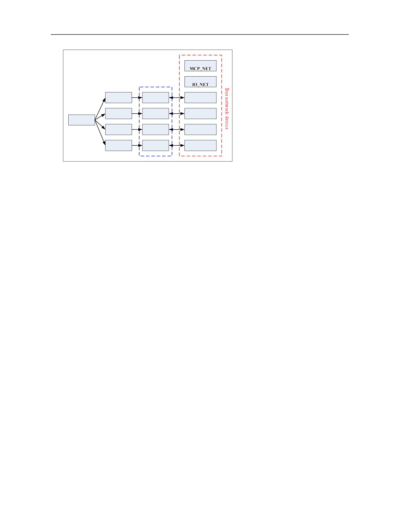
Figure
The mapping relationship between servo axis
device and logical axis in milling sytem
Device #5
Logical axis
Device #6
Coordinate axis
X axis
0
Device #7-AX
Coordinate axis
Y axis
Device #8-AX
1
Channel 0
Coordinate axis
Z axis
Device #9-AX
2
S axis
Coordinate axis
Device #10-AX
5
c. Inverse encoder feedback mark
0: Encoder feedback is directly inputted into the CNC system
1: Inverse encoder feedback is inputted into the CNC system
When spindle feedback rotation speed is displayed oppositely to the actual rotation direction, the parameter
can be set as 1.
d. Feedback position cycle mode
0: Feedback position does not adopt cycle count mode
1: Feedback position adopts cycle count mode
2: This mode is adopted when feed axis servo is switched to spindle
For linear feed axis or swing axis, this parameter should be set as 0. For rotary axis or spindle, this
parameter should be set as 1.
e. Feedback position cycle pulse count
When feedback position cycle is enabled, this parameter is used to set number of cycle pulses. Generally,
pulse count per revolution of axis should be filled out.
f. Encoder type
The parameter is used to specify type of servo axis encoder and feedback mode of Z pulse signal.
0 or 1: Incremental encoder with Z pulse signal feedback
2: Incremental linear grating ruler with distance-coded Z pulse signal feedback
3: Absolute encoder without Z pulse signal feedback
4: Reserved
5)
Analog spindle
a. Working mode
The parameter is used to set working mode of analog spindle.
0: There is no control command output
3: Speed mode
b. Logical axis number
The parameter is used to build the mapping relation between analog spindle device and logical axis.
-1: There is no mapping between device and logical axis
0-127: Mapping logical axis number
Figure
90