HNC-8 System Commissioning Manual (Milling System) V2.4 Series - page 1
Contents
Introduction
i
Contents
ii
1.
Introduction
1
1.1
808DM Series CNC System
1
1.2
818DM Series CNC System
4
2.
Common Hardware Configuration List
10
3.
Connection Diagram
12
3.1 Connection Diagram of 808D System Hardware
12
3.2 Connection Diagram Of 818D System Hardware
13
4.
Interface Definition
14
4.1
Definition of NCUC Bus Interface
14
4.2
Definition of IPC24V Power Supply Interface (POWER)
14
4.3
Definition of Handheld Unit Interface
15
4.4
Definition of Traverse Axis Servo Drive Encoder Interface
15
4.5
Definition of Second Encoder Interface of Traverse Axis Servo Drive
27
4.6
Definition of Spindle Servo Drive Encoder Interface
28
4.7
Definition of Second Encoder Interface of Spindle Servo Drive
35
4.8
Bus I/O Unit
37
5.
Preparation for Commissioning
46
5.1
Verification and Record
46
5.2
View System Information
46
5.3
Software Upgrade and Parameters, PLC Backup/Loading
46
5.4
Offline Commissioning
55
5.5 Step-by-step Power-on Principle
56
5.6
HNC-8 System Boot Failure and Cause
56
6.
Parameter Debugging
58
6.1
Parameter List
58
6.2
Verification of Device Parameters
60
6.3
Parameter Setting
63
6.4
Parameter Setting of HNC-8 Milling System
64
ii
7.
PLC Commissioning
93
7.1
HNC-8 PLC Structure
93
7.2
Working Principle of PLC Interface Signal
93
7.3
PLC Specification
95
7.4
Ladder Diagram Operation on CNC Controller
95
8.
Design Example of CNC Milling System
117
8.1
Electrical Schematic Diagram
117
8.2
Commissioning Procedure
120
Annexed Table A Technical Specifications of HSV-160U Series Servo Drive Unit and Motor Code
127
Annexed Table B Technical Specifications of HSV-180U Series Servo Drive Unit and Motor Code
129
Annexed Table C Technical Specifications of HSV-180US Series Spindle Drive Unit and Motor Code 135
Annexed Table D HNC-8 System MCP Panel Input/Output
140
Annexed Table E Detailed List of HNC-8 F-G Registers
142
Annexed Table F Detailed List of HNC-8 User PLC Events
149
ii
1. Introduction
1.1
808DM Series CNC System
1.1.1 Product Overview
808DM series CNC milling system is a bus CNC device based on mature HNC-8 CNC system platform and a
medium and high-end product of HNC-8 series CNC devices with high stability and reliability;
The product adopts aluminum alloy frame and has simple and elegant appearance. The hardware platform is
upgraded and overall hardware performance improves by 50%. The product adopts new platform software
which make it easier to develop customizable software;
MCP panel split structure, modular design, and customizable; 10.4 in. HBLCD;
Support two types of bus: NCUC and EtherCAT.
1.1.2 Product Features
Quick programmed path display function
Support rapid preview of graphics track while loading program, configure color of tool, display by different views,
display self-adaptive optimal proportion of view, and realize local zoom for user-friendliness.
Workpiece position measurement function
Support workpiece position measurement. After measuring coordinate points in the workpiece measurement
screen, the values automatically calculated according to measured coordinates will be set in the selected
coordinate system for user's preparation.
Tool automatic measurement function
Measurement specific to different application scenarios: Three tool setting modes are optional in the drop-down
box: "Single tool for single workpiece", "Single tool for multiple workpiece" and "Multiple tools for multiple
workpiece".
Comprehensive tool life management
Make statistics of tool life through management of cutting energy consumption and cutting distance. Various
life management modes can take effect simultaneously. Comprehensive statistics on tool life greatly improves
the accuracy of tool life management
Automatic pitch error import function
Directly import thread pitch error report text (.REN) generated by Renishaw laser interferometer or original data
of thread pitch error point
(.rtl) to automatically generate pitch compensation. Support incremental
compensation for the compensated axis when the .rtl file is imported again without the need to manually fill in
the pitch compensation parameters, reducing the workload of factory check and realizing efficient and accurate
pitch error compensation.
Configurable parameter classification function
Multi-custom classification and grouping according to parameter function: System parameters are divided into
several categories according to function, namely "Submenu", which is divided into groups according to
subfunction. Name available for customized classification and grouping can be prefixed with fast index
keyword to facilitate commissioning personnel to search. Classification parameter can be displayed and
modified according to permission. Axis parameter can be displayed by axis name in different columns to
facilitate to modify and contrastively view different axes.
1

Alarm help function
In "Alarm message" and "Alarm history" interfaces of the system, select corresponding alarm number and press
"HELP" key (shortcut key if there is no HELP key) on the NC panel to call corresponding alarm help
information. "Alarm cause" of corresponding alarm, "Response" when the system gives an alarm, "Solution"
after an alarm is given and corresponding "Reference" can be displayed, and can connect to Could in the later
period. The solution cases uploaded by customer service personnel also can enrich the help content.
Multibus control technology
Furnished with different HPC, HNC-8 system can support single or mixed connection of servo drive and I/O of
three types of real-time field bus NCUC, EtherCAT and MIII. Slave stations between different buses can realize
microsecond clock synchronization, which can meet the requirements for high speed and high accuracy of the
CNC system.
1.1.3 Product Parameters
Maximum number of channels is 1, 4 feed axes and 1 spindle are supported at most
Minimum resolution: 1um
Maximum movement speed: 24m/min
Automatic acceleration/deceleration control (straight line/S curve) reference point return
Machining graphic simulation and real-time
Coordinate system setting
CNC function
tracking
MDI function
M, S, T function
Machining graphic static simulation and
Internal secondary electronic gear
real-time tracking
Drilling cycle
Milling cycle (optional)
Minimum programming unit: 0.001mm,
Maximum size: 99999.999
degree
Maximum program lines: 2 billion lines
Programming in metric/inch
Absolute/incremental programming
Macro programming
CNC
programming
Subprogram call
Workpiece coordinate system setting
Automatic control of chamfer (fillet angle, right
Diameter/radius programming
angle)
Constant linear speed cutting function
Linear interpolation, no more than 3 axes
Interpolation
function
Circular interpolation, thread cutting, pitch error compensation
Tool
compensation
Tool length compensation
Tool nose radius compensation
function
Antistatic film programming panel and
8.4//TFT color LCD
Operation
operation panel of machine tool
function
PC standard keyboard interface
Handheld unit (optional)
2
Graphic display function and dynamic
Network communication function (optional)
real-time simulation
Infinite rotary axis function
Maximum setting speed 16000mm/min
Feed axis
Feed rate override 0%-150%
Rapid traverse override 0%-100%
function
Various reference point functions: unidirectional and bidirectional
Spindle speed: Controllable through PLC programming (maximum 32000rpm)
Spindle
Spindle override: 0%-150%
Spindle speed and override display
function
Gear ratio and number of gear ratio stages can be controlled through PLC programming, thread
function
Auxiliary
CW and CCW rotation of spindle Automatic tool changing Cooling ON/OFF
function
Built-in PLC, offer standard PLC routine, PLC online/offline programming and debugging
PLC function
function
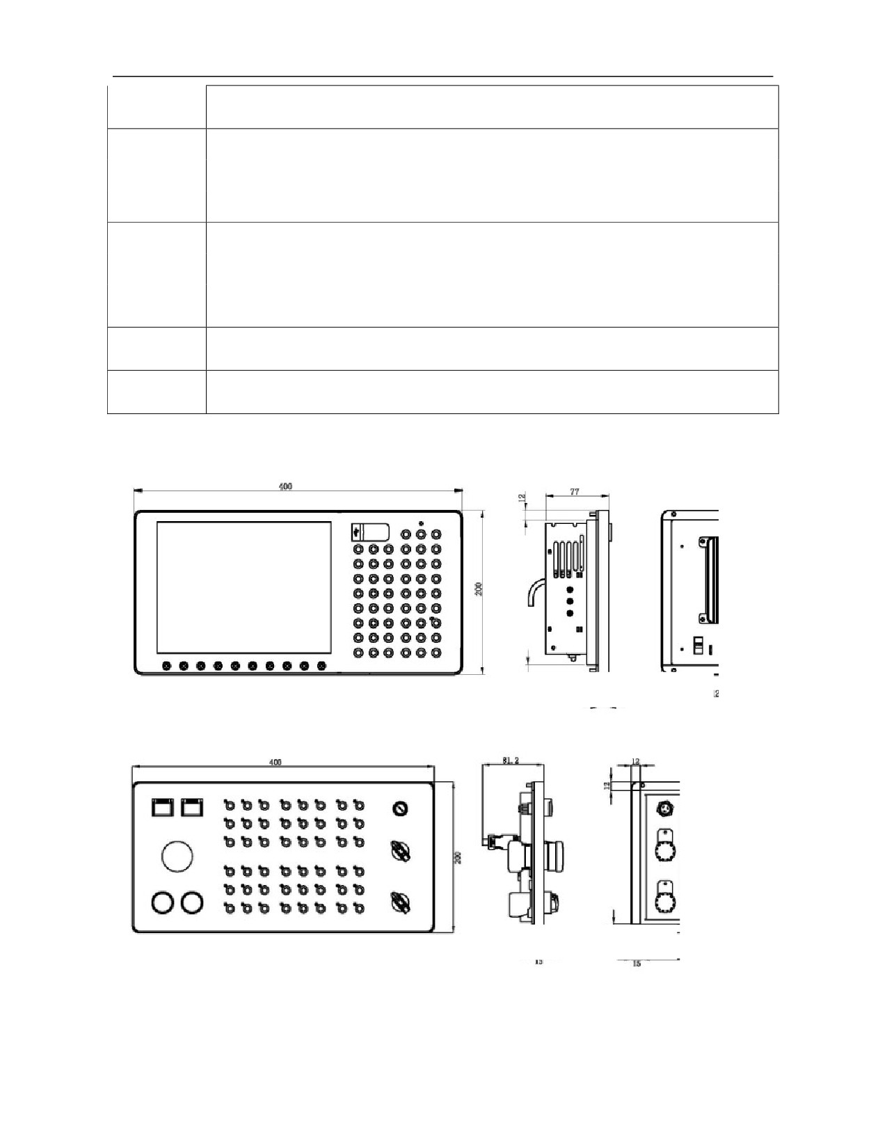
1.1.4 Product Size
Recommended mounting dimension:
380mm×180mm
Recommended mounting dimension:
380mm×180mm
3
1.2
818DM Series CNC System
1.2.1 Product Overview
HNC-818DM CNC milling system is a bus CNC device based on mature HNC-8 CNC system platform and a
medium and high-end product of HNC-8 series CNC devices with high stability and reliability;
The product adopts aluminum alloy frame and pendant installation and has simple and elegant appearance;
The hardware platform is upgraded and furnished with 8G SSD, with overall hardware performance improved
by 50%;
The product adopts an MCP panel split structure, modular design and combined crystal keys and is
customizable. The screen display has two specifications 12.1'' and 17'' and can be furnished with touch screen;
Support USB, Ethernet and other program expansion and data exchange functions;
Support two bus protocols NCUC and EtherCAT. Support various installations and more compatible with
appearance of machine tool. The newly designed IPC unit is thinner and smaller and is the best choice of
medium and high-end machine tools due to lower power consumption and higher operating rate.
1.2.2 Product Features
Smart surface machining technology (iSurfine)
Smart surface machining technology (iSurfine)-High-speed high-precision primary algorithms
Program read-ahead 2000 blocks
Sine and cosine flexible acceleration and deceleration control
High-speed nano interpolation
High-order fitting of small line block track
Speed smoothing
Sine and cosine flexible acceleration and deceleration control
High-speed nano interpolation
Low-order spline fitting
High-order spline fitting
Speed smoothing
Smart surface machining technology (iSurfine)-High-speed high-precision speed planning
Plan the optimal speed in real time according to tool path, reduce speed fluctuation during high-speed
machining to ensure consistency of adjacent tool path and speed.
Original G code program of new hardware remains unchanged, CUP performance increases by 38% and surface
quality and machining efficiency improve
Smart surface machining technology (iSurfine)-G code tool path optimization
Through the G code command quality analysis and G code tool path optimization, the smoothness and
continuity of the G code path are improved, and the surface quality of the processed parts is improved.
Before code optimization: Obvious vertical grains of side wall and obvious touch feeling.
Before code optimization: Smooth lines of side wall and no touch feeling.
Smart surface machining technology (iSurfine)-High-performance global surface optimization
High-performance machining global speed planning, speed shaping for variable speed intervals. Reduce speed
fluctuations during high-speed machining, ensure the consistency of adjacent toolpath speeds, improve
machining quality, and improve machining efficiency. Provide high-precision molds, auto parts, and 3C product
optimization solutions.
Sensor-based temperature compensation function
4

Temperature sensor is connected externally via HIO module to monitor temperature variation of temperature
sensitive points of machine tool. Moreover, with the temperature rising curve and dropping curve of the
machine tool temperature sensitive points, the compensation result of the machine tool thermal deformation is
formed, and the thermal stability of the machine tool accuracy is improved.
Triathlon health security
Carry out self-check of machine tool to obtain the ECG, inspect change of health indexes of machine tool, and
evaluate health condition of machine tool. Timely maintain machine tool according to evaluation result to
ensure healthy operation. Meanwhile, carry out horizontal comparison of health condition of similar machine
tools to ensure consistency of assembling and commissioning.
Feed axis load diagram
Make statistics of electric control big data of CNC system produced in the full life circle of guide screw,
analyze distribution of full-travel load of guide screw, evaluate state of guide screw according to visualized
statistical data, make effective and reasonable use of healthy area of guide screw, improve the operation
accuracy, and extend the service life of guide screw.
Intelligent management of tool life
Various tool life management improves rationality and accuracy of intelligent management of tool life and
effectively extends tool life.
Fault data recorder
The CNC system can store key data within 10s before fault occurs and replay 10s key fault data to effectively
help engineers identify fault cause and improve fault maintenance efficiency.
QR code diagnosis
Main information supported by the CNC system is outputted in the form of QR code. Scan QR code by mobile
phone to acquire state information of the CNC system and transmit the fault information to iNC-Cloud, and
query fault diagnosis case library and historical record of machine tool to analyze fault cause more accurately.
1.2.3 Product Parameters
Control channels
2 channels
Maximum number of control axes: 5 feed axes and 4 servo spindles
Maximum number of simultaneously-controlled axes: 3 axes (linear interpolation), 2 axes
Controlled axes
(circular interpolation)
Number of PLC control axes: 3 axes (support servo tool post)
Traverse axis: Low-voltage servo drive HSV-160U-020/030/050/075
Matching servo
drive
Spindle: HSV-180US-035/050/075/100
Feed axis is
Feed axis is switched to spindle: 4 feed axes are switched to spindles
switched to spindle
Coordinate value
G52 local coordinate system, G53 machine coordinate system, 6 workpiece coordinate
(system) and size
systems (G54-G59), 60 extended coordinate systems (G54.1-G54.60)
5

Coordinate plane selection (G17/G18/G19)
Position command range: μ level (IS-B) 214748.364 to +214748.364, 0.1μ level (IS-C)
21474.8364 to +21474.8364
Absolute/incremental programming, inch/metric, linear axis/swing axis/rotary axis
71 G commands, including rapid traverse positioning, linear interpolation, circular
interpolation, cylindrical interpolation, cylindrical spiral interpolation, polar coordinate
interpolation, imaginary axis specifying and sine interpolation, rigid tapping, mirroring
G code function
function, scaling function, rotation transformation function, drilling cycle, boring cycle,
tapping cycle, small line segment high-speed high-precision machining function, program
dwell, tool compensation, macroprogram call, skip, cycle, etc.
Rapid traverse speed: μ level
(IS-B)
0mm/min-60000mm/min,
0.1μ level
(IS-C)
0mm/min-24000mm/min
Rapid traverse override: Real-time override, a total of four levels: F0, 25%, 50% and 100%
Cutting feedrate: μ level
(IS-B)
0mm/min-30000mm/min,
0.1μ level
(IS-C)
Feed function
0mm/min-24000mm/min
Feed rate: 0~150% real-time adjustment, a total of 12 levels
Rapid traverse/cutting feed acceleration/deceleration: S curve acceleration/deceleration and
jerk control are set by parameters
Spindle speed: Given by S code or PLC signal, speed range is set by parameters
Spindle override: 50%-120% real-time override, in total of 8 levels
Constant linear speed control of spindle
Spindle function
C/S axis control
Analog voltage input/output: 4-way analog voltage input/output
Feedback of spindle encoder: Feedback of 2-way spindle encoder, feedback of spindle
encoder can be set
Magazine: up to 2 magazines are supported
Tool function
Tool length/radius compensation: 500 at most
6
Tool wear compensation: Support no more than 500
Tool radius compensation: C type tool compensation
Internal M command of system: (cannot be redefined) program stop M00; optional stop
Auxiliary function
M01; program end M02, M30; subprogram call M98; subprogram end M99; magazine call
M06; manual intervention M92, M93; other M commands are defined by PLC
PLC command: Built-in PLC, ladder diagram programming, 21 types of basic commands,
57 types of function commands
PLC classification: Two levels of PLC programs, the refresh cycle of the first level of
programs is 1ms
Maximum program lines: 8000 lines
PLC program: Online dynamic display, monitor, edit; support PLC warning and PLC alarm,
upload and download
PLC function
8-bit intermediate register (R): 2048 bytes (R0-R2047)
16-bit intermediate register (W): 512 bytes (W0-W255)
32-bit intermediate register (D): 1024 bytes (D0-D255)
Timer (T): 512
Counter (C): 512
32-digit data relay (B): 6888 bytes (B0-B1721)
User-defined parameters (P): 200 (P0-P199)
Program format: Program format ISO command standard, program name O+7 digits or
letters; block number N+7 digits; G+3 digits; coordinate value IP± 6 digits before the
decimal point and 4 digits after the decimal point; S+5 digits; T+3-digit tool number; M+3
digits; F+6 digits before the decimal point and 2 digits after the decimal point
Program capacity: 8G
Edit function: Program, program block, find, modify, delete, copy and past
Storage and edit
MDI function: Multiple lines of program blocks are allowed in MDI
function of
Macroprogram/subprogram call: Macro programming, 8 levels of subprogram nesting are
program
allowed
Reference point return: G28 reference point return
Block skip function: G31 block skip function is used for measurement of tool and workpiece
Programmable control function: Programmable data input (G10); tool offset, parameter and
G54 can be modified
7
Program check
Path preview, dryrun, machine tool lock, single block running, vertical/horizontal lathe
function
graphic simulation
Programming
Canned cycle, rigid tapping, direct input of drawing size, automatic chamfering, macro
simplifying
programming
Backlash compensation: 0mm-10mm, backlash compensation includes machining and rapid
traverse, and compensation frequency can be set by parameters
Compensation
Memory pitch error compensation: Each axis supports
2000 compensation points,
function
compensation points of each axis can be set by parameters, and pitch error compensation
table can be imported
808DM uses 10.4 in. true color LED
Machining path display
Program, setup, entry, tool compensation, diagnosis, position
Operating mode selection: Auto, single block, jog, incremental, MPG, reference point return
ON/OFF operation: Dryrun, block skip, optional stop, MST lock, machine tool lock, jog tool
Operation function
change, chuck clamping/release, tailstock loosening/tightening, rapid traverse override,
and display
spindle override, MPG override, spindle rotation CW, spindle stop, spindle rotation CCW,
spindle jog, hydraulic ON, cooling, lubrication, machine tool lighting, cyclic start, feed
hold, second feed hold, over travel release, power on, power off
Setup operation: Tool offset, tool compensation input; parameter setting of axis and servo
4-level operation permission management
Data interface: Ethernet and USB interfaces, realizing data transmission and network
function through interface
Data input/output: Program, system parameter, compensation value, and PLC program are
inputted/outputted through data interface
Network function: Ethernet communication, remote monitoring, remote diagnosis, remote
Communication
maintenance
function
Expansible bus I/O unit: HIO-1011N/P 16-point input; HIO-1021N/P 16-point output;
HIO-1073 4-way A/D input and 4-way D/A output; HIO-1041 2-way D/A output and 2-way
second encoder feedback
Servo drive interface: NCUC bus interface, EtherCat bus interface (Yaskawa M3 bus
interface is optional)
Emergency stop, hardware limit, first software travel check, second software travel check,
Safety function
multilevel permission data protection, spindle safety speed, feed safety speed, NC alarm,
PLC alarm, axis/servo alarm, tracking error monitoring, data backup and recovery
Fault log, machining log, file log, operation log, machining information, batch debugging,
Maintenance
parameter and PLC data backup, servo setup and servo load state monitoring, rigid tapping
function
oscilloscope
Thermal error compensation with temperature sensor, machining parameter optimization,
Intelligent function
intelligent high-speed high-precision optimization, full life cycle screw load statistical chart,
intelligent tool life management, health security function, cloud CNC
8
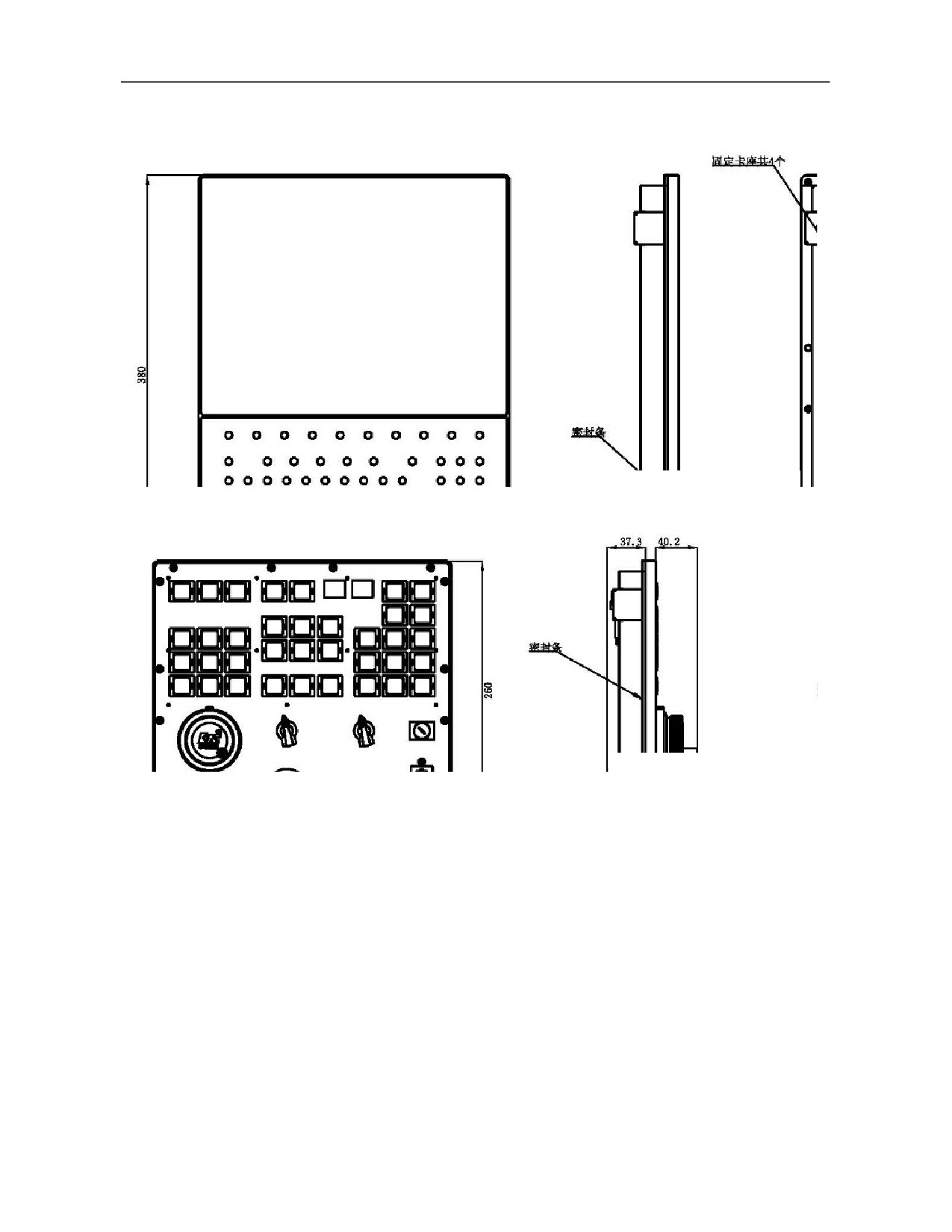
1.2.4 Product Size
Recommended mounting dimension:
272mm×362mm
Recommended mounting dimension:
272mm×242mm
9

2. Common Hardware Configuration List
1) 808D controller+160U traverse axis servo +180U spindle servo +HIO-1200 series I/O unit
SN
Function
Quantity
1
Milling CNC controller /HNC-808D/horizontal type/NC unit
1
2
Milling CNC controller /HNC-808D/MCP unit/without MPG
1
3
PLC unit/HIO-1200-M1/detached IO unit baseplate +terminal board_V1.1
1
4
Bus cable/HCB-0000-2102-005/5m
2
5
Bus cable/HCB-0000-2102-001/1m
3
6
Bus cable /HCB-0000-2102-002/2m
1
7
Servo drive/HSV-160U-030/hardware current loop
2
8
Servo drive/HSV-160U-050 (Infineon PIM)
1
9
130ST-M10015LMB
2
10
130ST-M15015LMBZ
1
11
Power line /HCB-9160-1111-005-CG/5m/ detachable
2
12
Encoder cable/HCB-9160-0122-005-DB/5m
2
13
Power line/HCB-9160-1112-005-CH/5m
1
14
Brake line/HCB-9016-4100-005-CD/purple/5m
1
15
Encoder cable/HCB-9160-0122-005-DB/5m
1
16
Spindle drive/HSV-180US-050(Infineon PIM)
1
17
Spindle motor/CTB-45P5ZGB15-60H5GP
1
18
Electric reactor/ACL-5.5KW/ 5.5KW/15A/three-phase input/screw
1
19
Braking resistor/51Ω/1100W/RXLG/Bengbu Vanke/plug-in
1
20
Power line/HCB-9018-3000-005-CH/5m/detachable
1
21
Encoder cable/HCB-9180-2201-005-DB/5m
1
22
MPG/HWL-1013-3/3 axes
1
10

2) 818D system +180U traverse axis servo drive +180U spindle servo+HIO-1000 series IO unit
SN
Function
Quantity
1
Milling CNC controller/HNC-818D/NC unit
1
2
Milling CNC controller/HNC-818D/MCP unit/ without MPG
1
3
PLC unit /HIO-1009/9-slot baseplate
1
4
PLC unit /HIO-1061/NCUC live wire port communication board
1
5
PLC unit /HIO-1011P/PNP type input board
2
6
PLC unit /HIO-1011N/NPN type input board
1
7
PLC unit /HIO-1021P/PNP type output board
2
8
PLC unit /HIO-1021N/NPN type output board
1
9
Bus cable /HCB-0000-2102-007/7m
2
10
Bus cable /HCB-0000-2102-002/2m
1
11
Bus cable/HCB-0000-2102-0D5/0.5m
5
12
MPG/HWL-1013-3/3 axes
1
13
Switching power supply/HPW-145U/145W/24V output/V1.7
1
14
Power supply line/HCB-0008-1010-007-CD/7m
1
15
Spindle drive/HSV-180US-075(Infineon PIM)
1
16
Spindle motor/CTB-47P5ZGB15-60H5GP
1
17
Braking resistor/20Ω/2000W/RXLG /screw
1
18
Electric reactor/ACL-7.5KW /7.5KW/20A/three-phase input/screw
1
19
Power line/HCB-9018-3000-005-CH/5m/detachable
1
20
Encoder cable/HCB-9180-2201-005-DB/5m
1
21
Servo drive/HSV-180UD-075(Infineon PIM)
3
22
Braking resistor/20Ω/1200W/RXLG/screw
3
23
Electric reactor/ACL-22KW /22KW/60A/three-phase AC/screw
1
24
180ST-M23020HMBB/spigot 114.3
2
25
180ST-M27020HMBBZ/DC24V/spigot 114.3
1
26
Power line /HCB-9180-1114-007-CH/orange/7m
1
27
Encoder cable/HCB-9160-0122-007-DB/7m
1
28
Power line/HCB-9180-1114-005-CH/orange/5m
1
29
Encoder cable/HCB-9160-0122-005-DB/5m
1
30
Power line/HCB-9180-1114-005-CH/orange/5m
1
31
Brake line/HCB-9016-4100-005-CD/purple/5m
1
32
Encoder cable/HCB-9160-0122-005-DB/5m
1
11
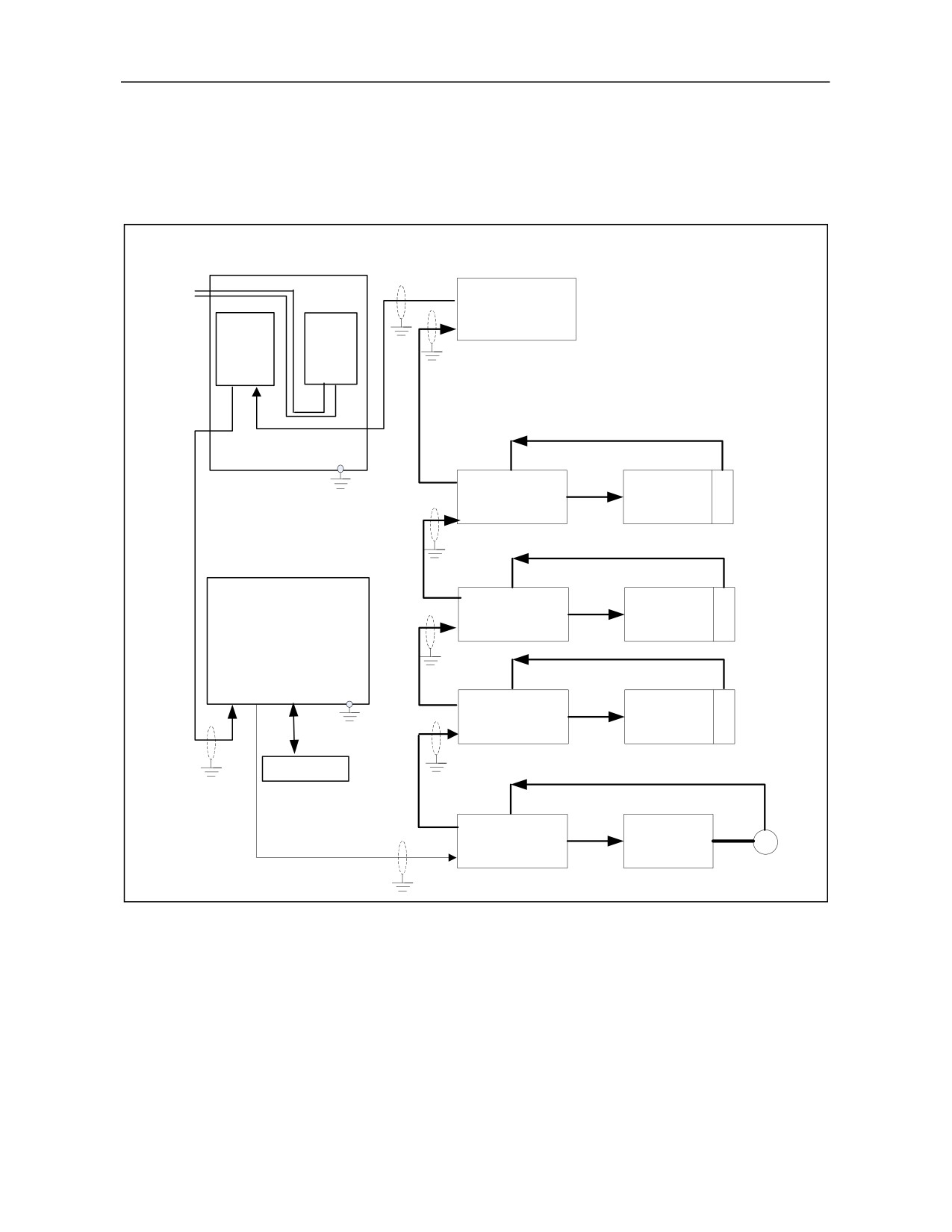
3. Connection Diagram
3.1 Connection Diagram of 808D System Hardware
HNC-808D-MU CNC device
NCUC bus
AC 220V
X2B
input
Bus I/O unit
X2A
IPC
UPS
unit
power
NCUC bus
OUT IN
Z axis encoder
XS4Z axis drive
Servo motor
Z
HSV-160UD
XS3
NCUC bus
Y axis encoder
XS4Y axis drive
Servo motor
Y
HSV-160UD
XS3
MCP unit
NCUC bus
X axis encoder
XS6A XS6B
XS4X axis drive
Servo motor
Z
HSV-160UD
XS3
NCUC bus
Handheld unit
NCUC bus
XS4
Spindle drive
Spindle
NCUC bus
HSV-180US
motor
XS3
Spindle encoder
12
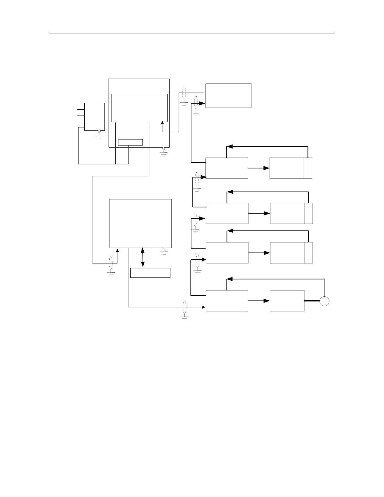
3.2 Connection Diagram Of 818D System Hardware
HNC-818D-MU CNC device
NCUC bus
X2B
Bus I/O unit
X2A
AC
IPC unit
220V
UPS
POWER
OUT IN
NCUC bus
input
power
POWER
Z axis encoder
XS4Z axis drive
Servo motor Z
HSV-180UD
XS3
NCUC bus
Y axis encoder
XS4Y axis drive
Servo motor Y
HSV-180UD
XS3
MCP unit
NCUC bus
X axis encoder
XS6A XS6B
XS4X axis drive
Servo motor X
HSV-180UD
XS3
NCUC bus
Handheld unit
NCUC bus
XS4
NCUC bus
Spindle drive
Spindle
motor
XS3HSV-180US
Spindle encoder
13
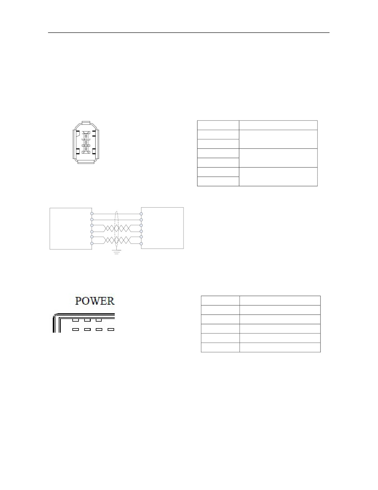
4. Interface Definition
4.1 Definition of NCUC Bus Interface
Signal
Description
6: RXD-
5: RXD+
24V
DC 24V voltage
4: TXD-
3: TXD+
GND
2: GND
1: 24V
TXD+
Data transmission
TXD-
RXD+
Data receiving
RXD-
Connection diagram of NCUC bus cable
Shi eldi ng
layer
24V
1
1
24V
GND 2
2
GND
TXD+ 3
5RXD+
TXD- 4
6 RXD-
RXD+5
3TXD+
RXD-
6
4
TXD-
4.2 Definition of IPC24V Power Supply Interface (POWER)
Signal
Description
24V UPS
DC 24V with UPS function
GND
Power ground
SGND
Signal ground
ACFail
Power failure detection signal
1:24V UPS 2: GND 3: SGND 4: ACFail 5:PE
PE
Protective earth
14
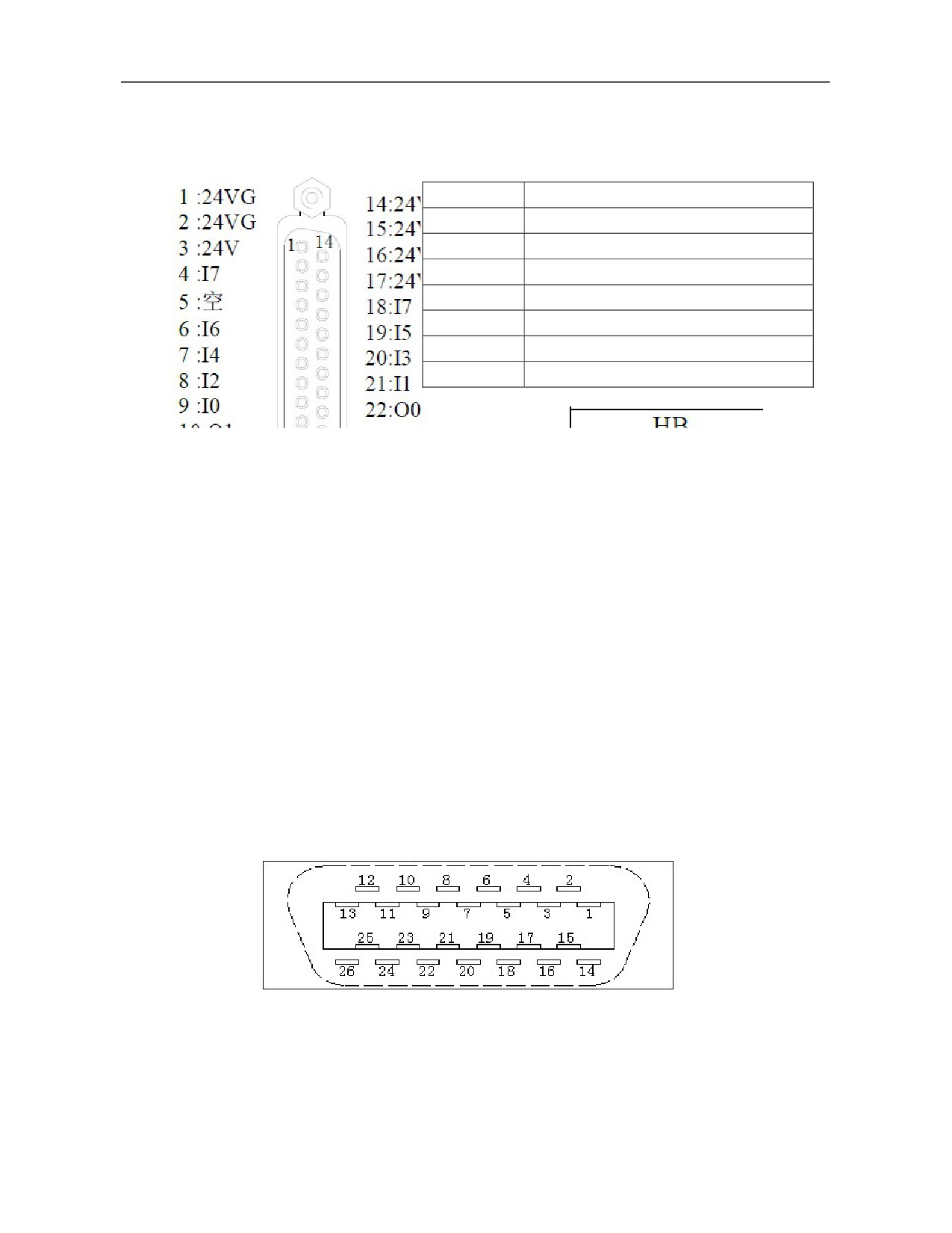
4.3 Definition of Handheld Unit Interface
Signal
Description
24V, 24VG
DC24V power output
I7
Handheld unit emergency stop button
I0 to I6
Handheld unit input switch value
O0 to O3
Handheld unit output switch value
HA
Handwheel A phase
HB
Handwheel B phase
+5V, 5VG
Handwheel DC5V power output
4.4 Definition of Traverse Axis Servo Drive Encoder Interface
160U and 180U encoder interfaces correspond to XS1 and XS5 respectively and are defined consistently.
HSV-160U (basic function type) includes HSV-160UP (full-function type) and HSV-160UD series, which
support different encoder protocols.
HSV-160U series can be used with composite incremental encoders and Tamagawa and Nikon absolute
encoders.
HSV-160UP series can be used with composite incremental encoders and Tamagawa, Nikon, ENDAT2.1,
HiperFACE and BISS absolute encoders, support dual encoder interfaces, and can be connected to grating ruler
and other position feedback devices to realize full-closed loop control.
HSV-180UD-035, 050, 075, 090, 100 and 150 AC servo drive unit have uniform servo motor encoder interface
and can be used with composite incremental encoders and Tamagawa and Nikon absolute encoders.
HSV-180UD-035C, 050C, 075C, 090C, 100C, 150C, 200, 300 and 450 as well as HSV-180U1D-100, 150, 200
and 300 AC servo drive units have uniform servo motor encoder interface and can be used with composite
incremental encoders and Tamagawa, Nikon, Heidenhain, SICK, HiperFACE and BISS C absolute encoders,
support dual encoder interfaces, and can be connected to grating ruler and other position feedback devices to
realize full-closed loop control.
Input interface plug pin of servomotor encoder
(facing the plug pin)
15
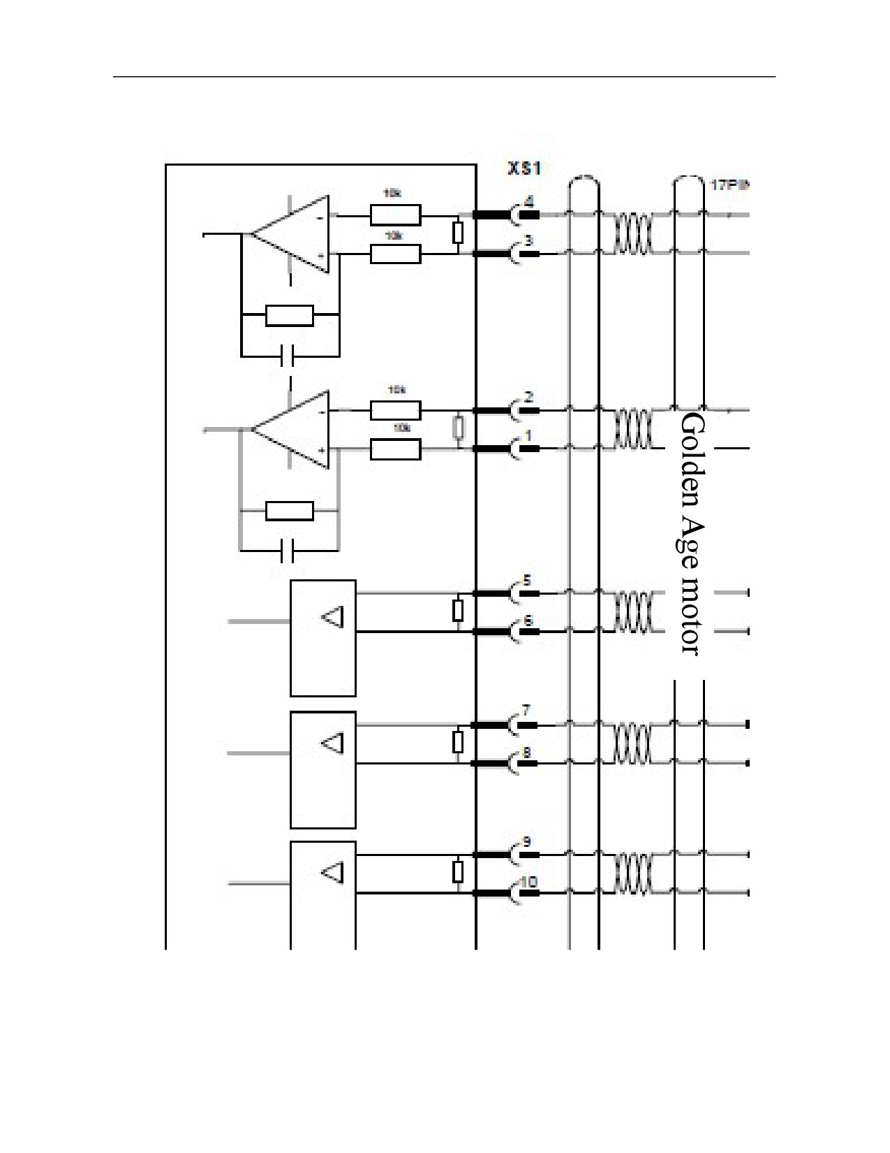
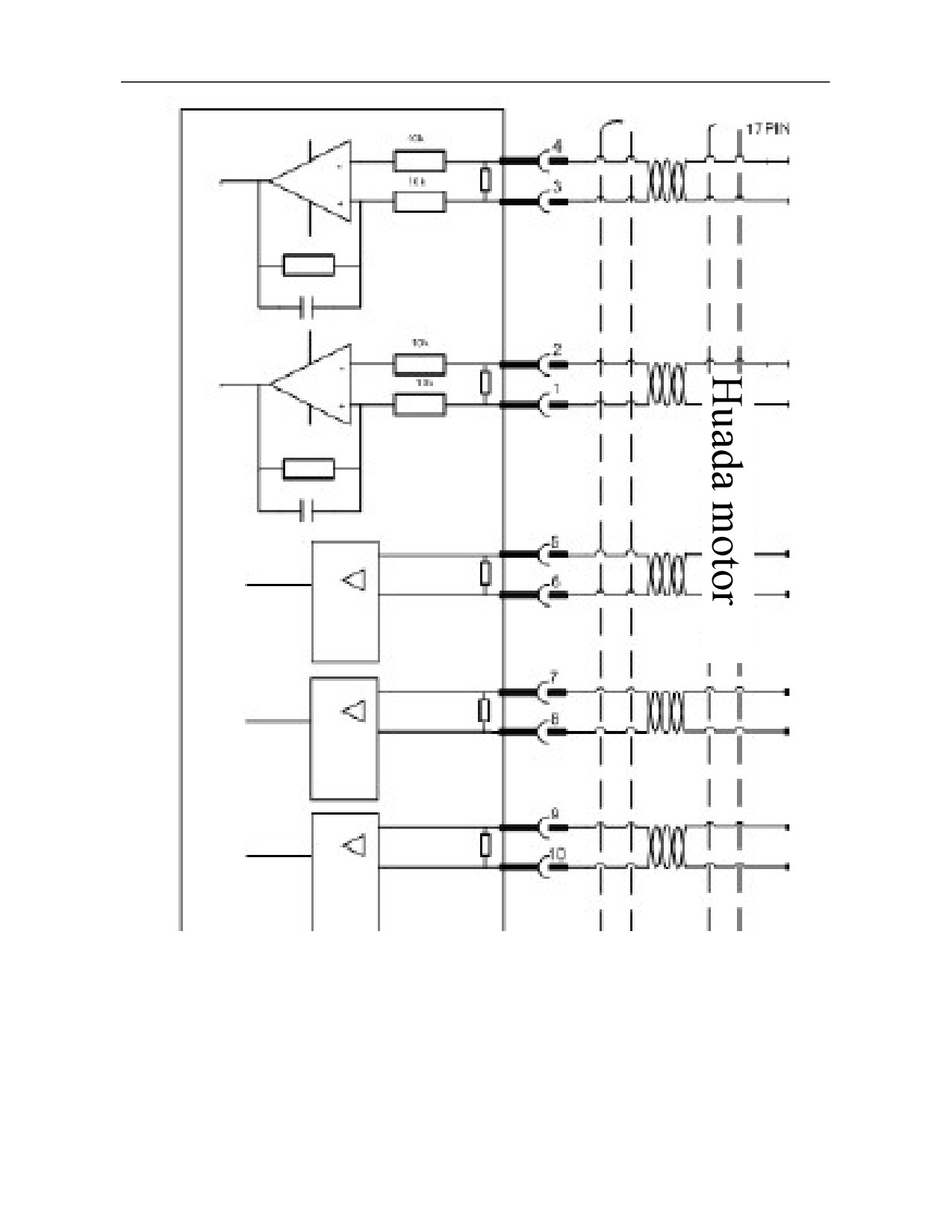
4.4.1 Servo Drive Connects to Composite Optical Encoder
Optical encoder
16
Optical encoder
17
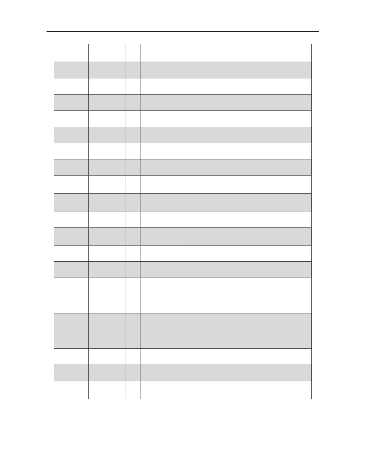
Terminal
Terminal
I/O
Signal
Function
number
symbol
1
A+/SINA+
I
Encoder A+ input
Connect to servomotor optical encoder A+
2
A-/SINA-
I
Encoder A- input
Connect to servomotor optical encoder A-
3
B+/COSB+
I
Encoder B+ input
Connect to servomotor optical encoder B+
4
B-/COSB-
I
Encoder B- input
Connect to servomotor optical encoder B-
5
Z+
I
Encoder Z+ input
Connect to servomotor optical encoder Z+
6
Z-
I
Encoder Z- input
Connect to servomotor optical encoder Z-
7
U+/DATA+
I
Encoder U+ input
Connect to servomotor optical encoder U+
Connect to servomotor optical encoder U-
8
U-/DATA-
I
Encoder U- input
V+/CLOCK
9
I
Encoder V+ input
Connect to servomotor optical encoder V+
+
10
V-/CLOCK-
I
Encoder V- input
Connect to servomotor optical encoder V-
Encoder W+
11
W+
I
Connect to servomotor optical encoder W+
input
12
W-
I
Encoder W- input
Connect to servomotor optical encoder W-
13,26
Reserved
1. Supply +5V power to the connected optical
16,17,
encoder.
+5V
O
Output +5V
18,19
2. When cable is long, multiple core wires
should be connected in parallel.
1. Connect to 0V signal of servomotor optical
encoder.
23,24,25
GNDD
O
Signal ground
2. When cable is long, multiple core wires
should be connected in parallel.
20,22
Reserved
21
Reserved
Connect to PE signal of servomotor optical
14,15
PE
O
Shielded signal
encoder.
18
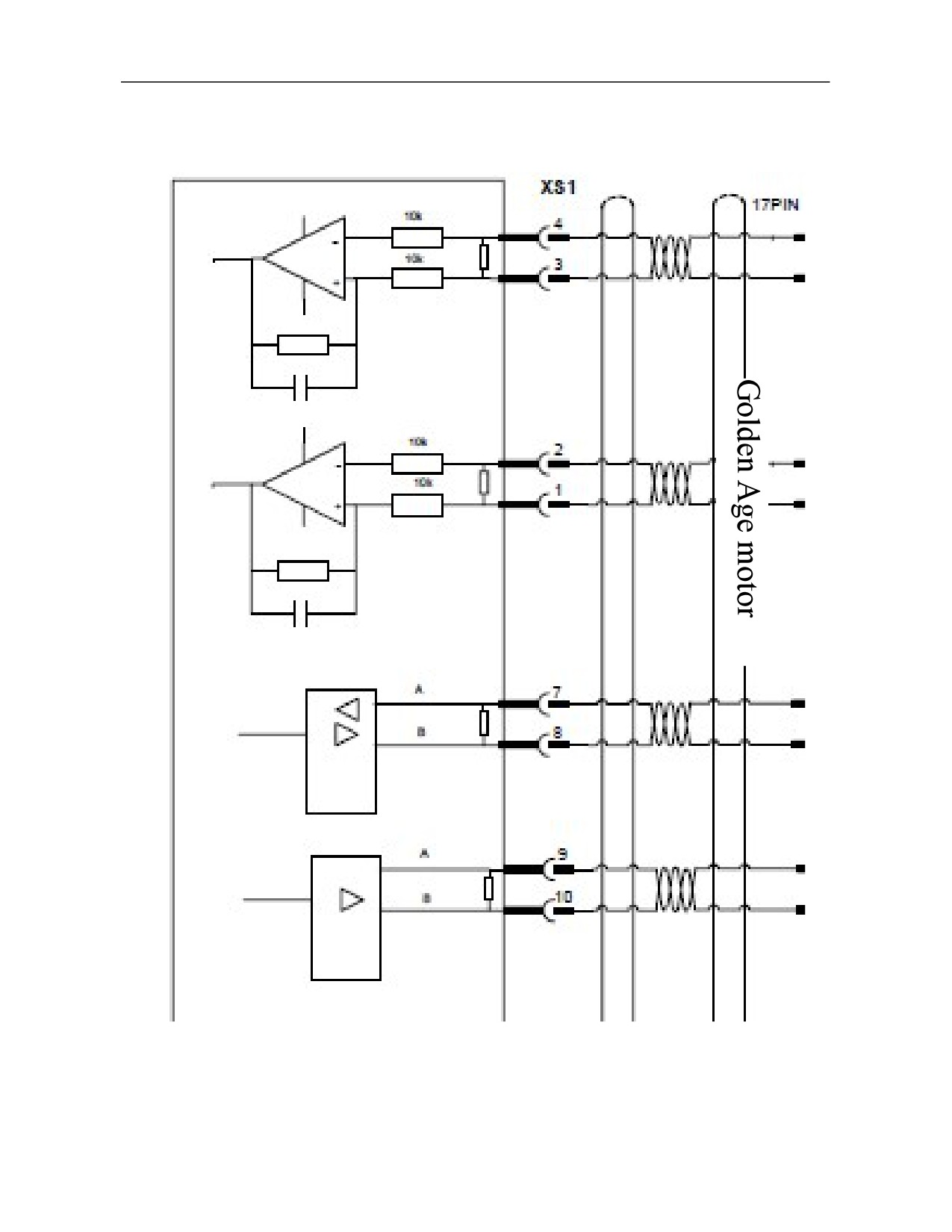
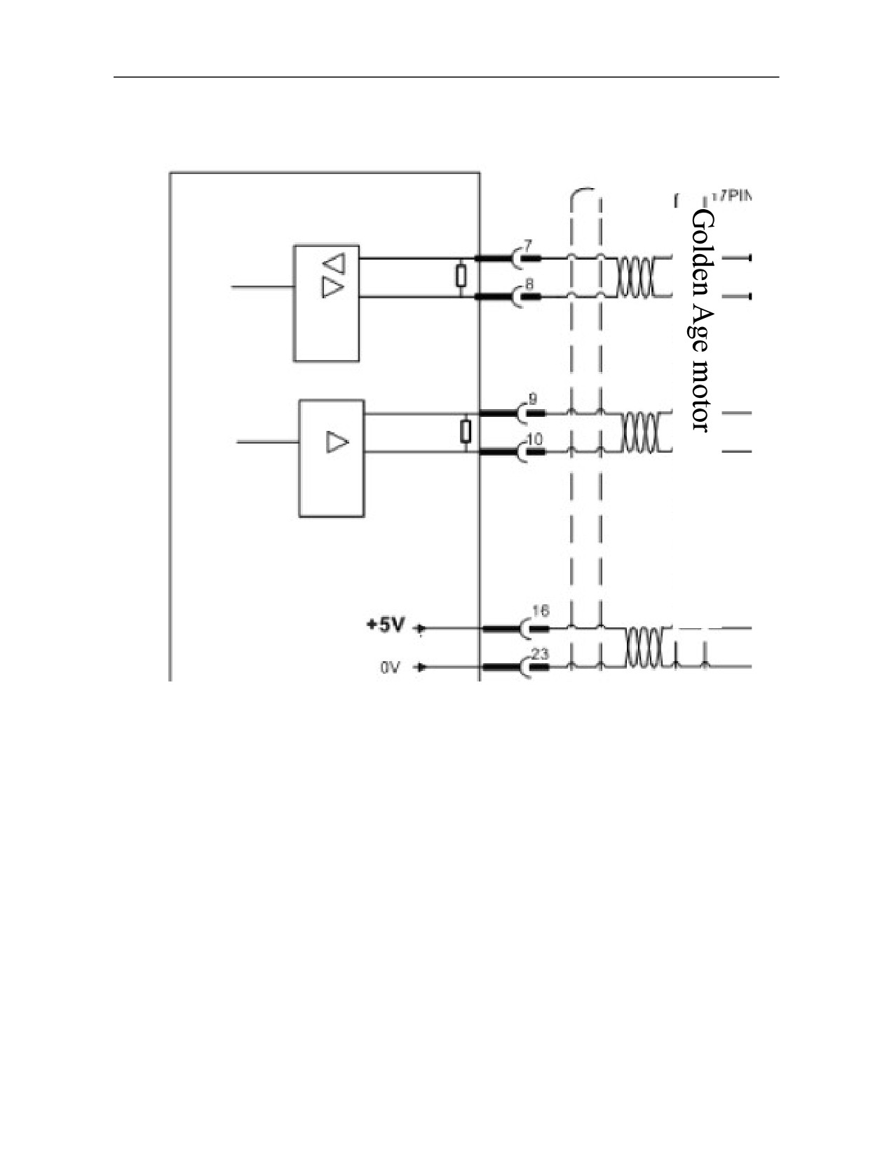
4.4.2
Servo Drive Connects to Absolute Encoder of ENDAT2.1 Protocol
Endat2.1 encoder
19
Terminal
Terminal symbol
I/O
Signal
Function
number
Connect to SINA+ of
1
A+/SINA+
I
Encoder A+ input
servomotor ENDAT2.1 protocol encoder
Connect to SINA- of servomotor
2
A-/SINA-
I
Encoder A- input
ENDAT2.1 protocol encoder
Connected to COSB+ of servomotor
3
B+/COSB+
I
Encoder B+ input
ENDAT2.1 protocol encoder
Connected to COSB- of servomotor
4
B-/COSB-
I
Encoder B- input
ENDAT2.1protocol encoder
5,6
Reserved
Connect to DATA+ signal of servomotor
7
U+/DATA+
I/O
Encoder DATA+
ENDAT2.1 protocol encoder
Connect to DATA- signal of servomotor
8
U-/DATA-
I/O
Encoder DATA-
ENDAT2.1 protocol encoder
Connect to CLOCK+ signal of servomotor
9
V+/CLOCK+
O
Encoder CLOCK+
ENDAT2.1 protocol encoder
Connect to CLOCK- signal of servomotor
10
V-/CLOCK-
O
Encoder CLOCK-
ENDAT2.1 protocol encoder
11,12
Reserved
13,26
Reserved
1. Supply +5V power to the connected
16,17,
ENDAT2.1 protocol encoder.
+5V
O
Output +5V
18,19
2. When cable is long, multiple core wires
should be connected in parallel.
1. Connect to 0V signal of servomotor
ENDAT2.1 protocol encoder.
23,24,25
GNDD
O
Signal ground
2. When cable is long, multiple core wires
should be connected in parallel.
20,22
Reserved
21
Reserved
Connect to PE signal of servomotor
14,15
PE
O
Shielding layer
ENDAT2.1 protocol encoder.
20
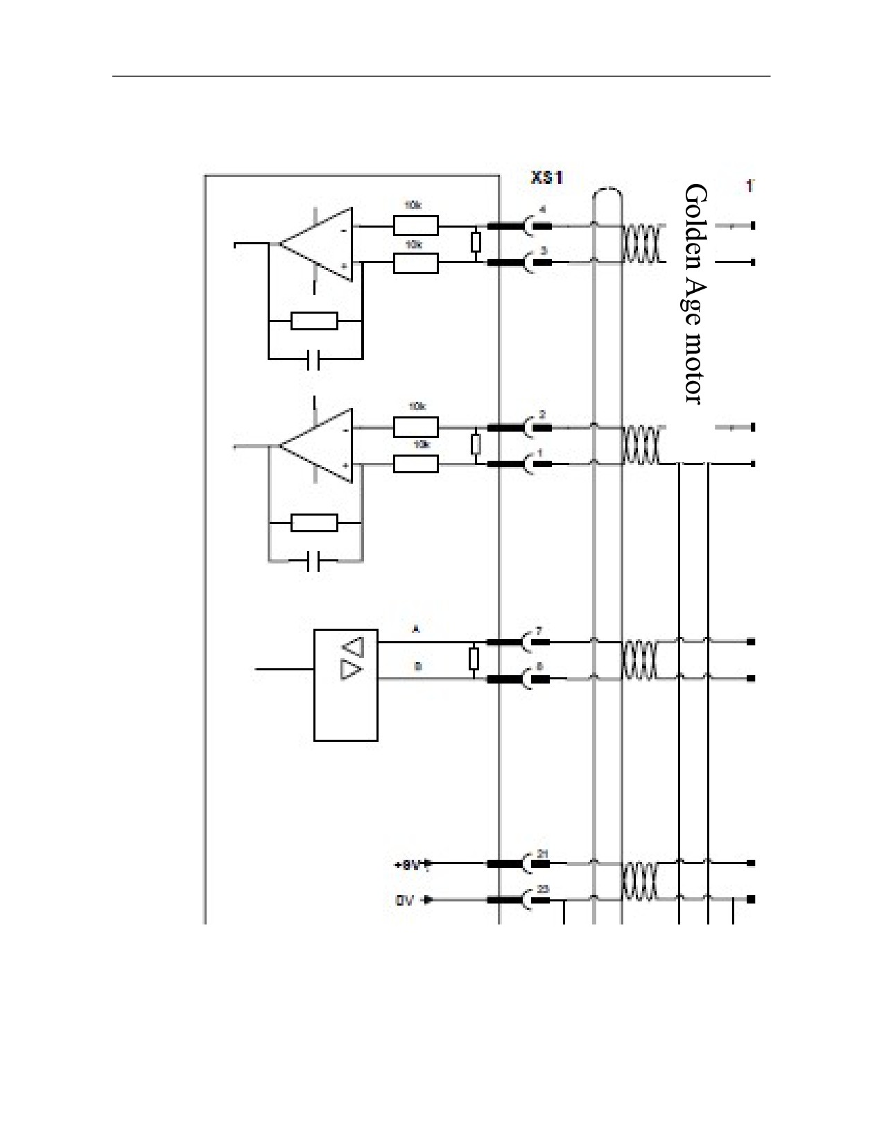
4.4.3 Servo Drive Connects to Absolute Encoder of BISS Protocol
BISS protocol
encoder
21
Terminal
Terminal
I/O
Signal
Function
number
symbol
1,2
Reserved
I
3,4
Reserved
I
5,6
Reserved
Connect to DATA+ signal of servomotor
7
U+/DATA+
I
Encoder DATA+
BISS protocol encoder
Connect to DATA- signal of servomotor
8
U-/DATA-
I
Encoder DATA-
BISS protocol encoder
Connect to CLOCK+ signal of servomotor
9
V+/CLOCK+
O
Encoder CLOCK+
BISS protocol encoder
Connect to CLOCK- signal of servomotor
10
V-/CLOCK-
O
Encoder CLOCK-
BISS protocol encoder
11,12
Reserved
13,26
Reserved
1. Supply + 5V power to the connected
16,17,
BISS protocol encoder.
+5V
O
Output +5V
18,19
2. When cable is long, multiple core wires
are connected in parallel.
1. Connect to 0V signal of servomotor
BISS protocol encoder.
23,24,25
GNDD
O
Signal ground
2. When cable is long, multiple core wires
should be connected in parallel.
20,22
Reserved
21
Reserved
Connect to PE signal of servomotor
14,15
PE
O
Shielding layer
BISS protocol encoder.
22
4.4.4 Servo Drive Connects to Absolute Encoder of HiperFACE Protocol
23
Terminal
Terminal
I/O
Signal
Function
number
symbol
Connect to COS+ of servomotor HiperFACE
1
A+/SINA+
I
Encoder A+ input
protocol encoder
Connect to REFCOS of servomotor HiperFACE
2
A-/SINA-
I
Encoder A- input
protocol encoder
Connect to SIN+ of servomotor HiperFACE
3
B+/COSB+
I
Encoder B+ input
protocol encoder
Connect to REFSIN of servomotor HiperFACE
4
B-/COSB-
I
Encoder B- input
protocol encoder
5,6
Reserved
Connect to DATA+ signal of servomotor
7
U+/DATA+
I/O
Encoder DATA+
HiperFACE protocol encoder
Connect to DATA- signal of servomotor
8
U-/DATA-
I/O
Encoder DATA-
HiperFACE protocol encoder
9,10
Reserved
11,12
Reserved
13,26,
Reserved
16,17,18,19
Reserved
1. Supply +9V power to the connected
HiperFACE protocol encoder.
21
+9V
O
Output +9V
2. When cable is long, multiple core wires are
connected in parallel.
1. Connect to 0V signal of servomotor
HiperFACE protocol encoder.
23,24,25
GNDD
O
Signal ground
2. When cable is long, multiple core wires are
connected in parallel.
20,22
Reserved
Connect to PE signal of servomotor HiperFACE
14,15
PE
O
Shielding layer
protocol encoder.
24
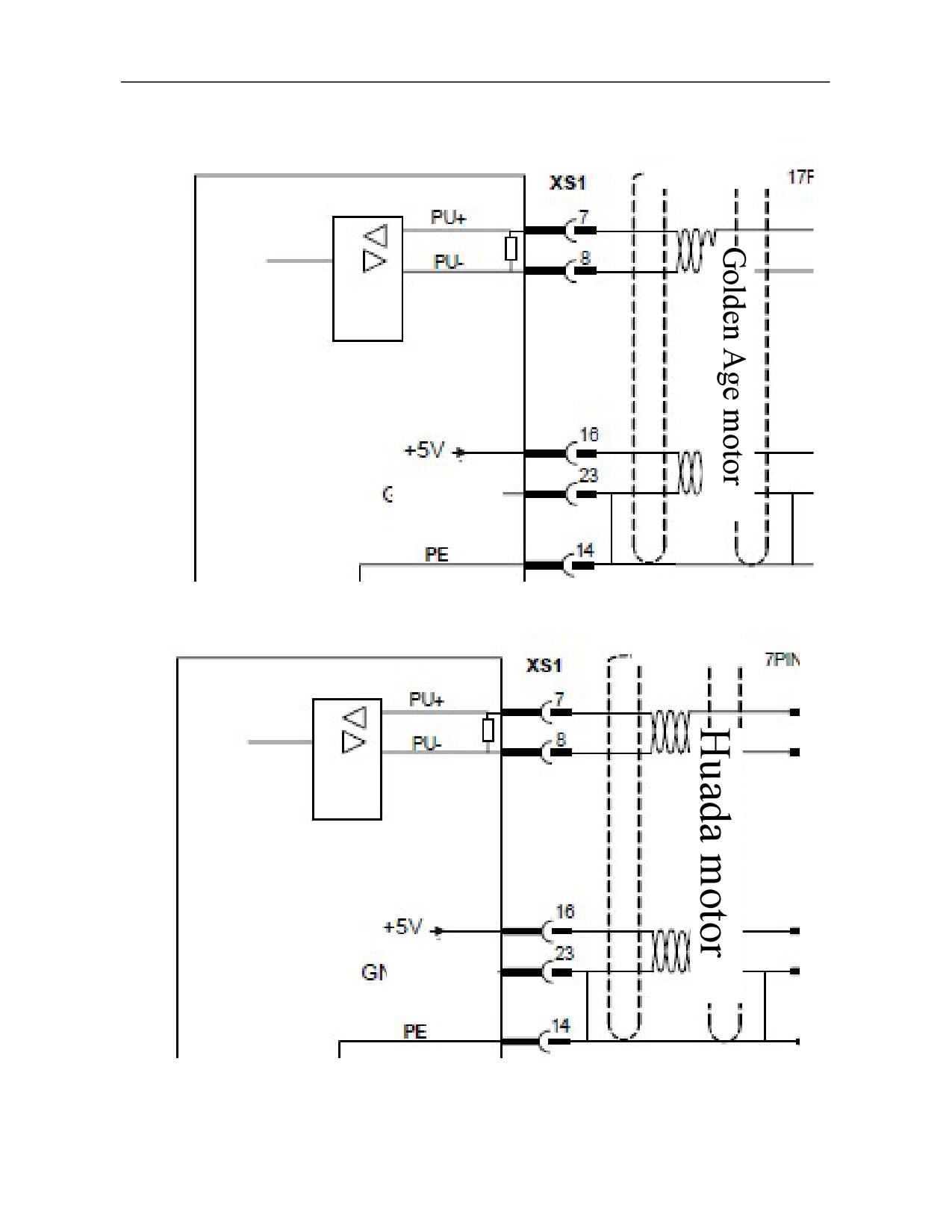
4.4.5 Servo Drive Connect to Absolute Encoder Of TAMAGAWA Protocol
Tamagawa absolute encoder
Powered by +3.6V
battery in the cell
box on the encoder
cable
Tamagawa absolute encoder
Powered by +3.6V
battery in the cell
box on the encoder
cable
Note: 1. When TAMAGAWA absolute encoder is connected, encoder cable with cell box is recommended.
2. When TAMAGAWA absolute encoder is used, users are suggested to buy encoder cable with cell box
produced by HCNC company. After the drive is powered off, the encoder is powered by the cell box.
25
Terminal
Terminal
I/O
Signal
Function
number
symbol
1,2
Reserved
I
3,4
Reserved
I
5,6
Reserved
I
Connect to DATA+ signal of servomotor
7
U+/DATA+
I
Encoder DATA+
TAMAGAWA encoder
Connect to DATA- signal of servomotor
8
U-/DATA-
I
Encoder DATA-
TAMAGAWA encoder
9,10
Reserved
O
11,12
Reserved
13,26
Reserved
1. Supply + 5V power to the connect TAMAGAWA
16,17,
encoder.
+5V
O
Output +5V
18,19
2. When cable is long, multiple core wires
are connected in parallel.
1. Connect to 0V signal of servomotor TAMAGAWA
encoder servomotor optical encoder.
23,24,25
GNDD
O
Signal ground
2. When cable is long, multiple core wires should be
connected in parallel.
20
Reserved
O
22
Reserved
O
21
Reserved
O
Connect to PE signal of servomotor TAMAGAWA
14,15
PE
O
Shielding layer
protocol encoder.
Note: When TAMAGAWA absolute encoder is connected, encoder cable with cell box is recommended.
Note:
1. Pins of the same name have been short circuited on the internal circuit board.
2. Diameter of encoder cable: Shielded cable (stranded shielded cable) whose sectional cross area is ≥0.12mm2
(AWG24-26) should be adopted and the shielding layer must be connected to the metal shell of connection plug.
3. Length of encoder cable: Cable should be as short as possible and its shielding layer should be connected to
GNDD signal of encoder power supply (to avoid intervention of encoder feedback signal).
4. Wiring: Keep away from power line to prevent intervention. Please install surge absorption elements for
inductive elements (coil) in relevant circuits: DC coil is connected in parallel reversely
Freewheel diode and AC coil are connected to RC absorption circuit in parallel.
5. When the drive unit is connected to different encoders, the matching encoder cables are different. Please
connect them upon confirmation; otherwise, burnout of encoder may occur.
26
4.5 Definition of Second Encoder Interface of Traverse Axis Servo Drive
160UP series, HSV-180UD-035C,
050C,
075C,
090C,
100C,
150C,
200,
300 and
450 as well as
HSV-180U1D-100, 150, 200 and 300 drives support full-closed loop second encoder function and correspond to
interfaces XS5 and XS6.
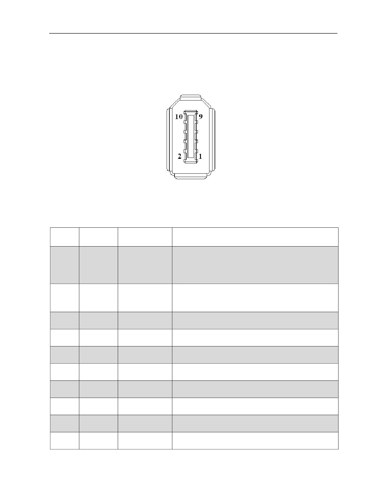
The second position feedback signal input interface socket (facing socket)
4.5.1 Connect Incremental Encoder
Terminal
Terminal
Signal
Function
number
symbol
1. Provide +5V power supply to the encoder connected to XS6.
2. Connected to power supply pin of the encoder.
1
+5V
Output +5V
3. When cable is long, multipole core wires should be
connected in parallel.
1. Connect to 0V pin of the encoder.
2
GNDD
Signal earth
2. When cable is long, multiple core wires should be connected
in parallel.
3
A+/SINA+
Encoder A+ input
Connect to A+ (or SINA+) of worktable position encoder
4
A-/SINA-
Encoder A- input
Connect to A- (or SINA-) of worktable position encoder
5
B+/COSB+
Encoder B+ input
Connect to B+ (or COSB+) of worktable position encoder
6
B-/COSB-
Encoder B- input
Connected to B- (or COSB-) of worktable position encoder
7
DATA+
Encoder DATA+
Connect to Z+ (or R+) of worktable position encoder
8
DATA-
Encoder DATA-
Connect to Z- (or R-) of worktable position encoder
9
Reserved
10
Reserved
27
4.5.2 Connect Endat2.1/2.2 Protocol Absolute Encoder
Terminal
Terminal
Signal
Function
number
symbol
1. Supply +5V power to Endat2.1/2.2 protocol encoder
connected to XS5.
Power supply output
1
+5V
2. Connect to power supply pin of the encoder.
+
3. When cable is long, multiple core wires should be
connected in parallel.
1. Connect to 0V pin of the encoder.
Power supply output
2
GNDD
2. When cable is long, multiple core wires should be
-
connected in parallel.
A+/SINA
Connect to SINA+ of worktable position ENDAT2.1
3
Encoder A+ input
+
protocol encoder
Connect to SINA- of worktable position ENDAT2.1 protocol
4
A-/SINA-
Encoder A- input
encoder
B+/COSB
Connect to COSB+ of worktable position ENDAT2.1
5
Encoder B+ input
+
protocol encoder
Connect to COSB- of worktable position ENDAT2.1
6
B-/COSB-
Encoder B- input
protocol encoder
Connect to DATA+ of worktable position ENDAT2.1
7
DATA+
Encoder DATA+
protocol encoder
Connect to DATA- of worktable position ENDAT2.1
8
DATA-
Encoder DATA-
protocol encoder
Encoder
Connect to CLOCK+ of worktable position ENDAT2.1
9
CLOCK+
CLOCK+
protocol encoder
Encoder
Connect to CLOCK- of worktable position ENDAT2.1
10
CLOCK-
CLOCK-
protocol encoder
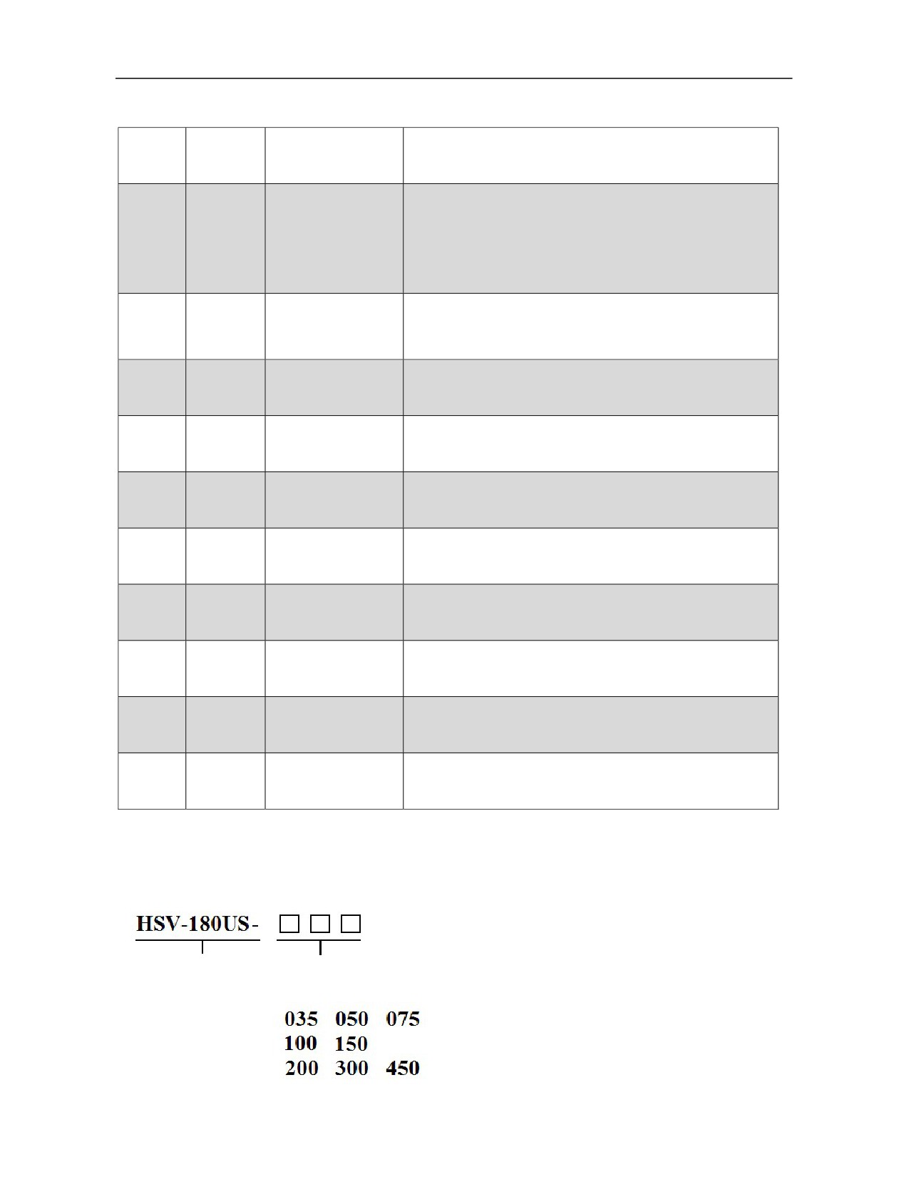
4.6 Definition of Spindle Servo Drive Encoder Interface
Specification and model of spindle drive unit:
Spindle drive unit
Specification
28
//////////////////////