HNC-8 System Commissioning Manual (Milling System) V2.4 Series - page 5
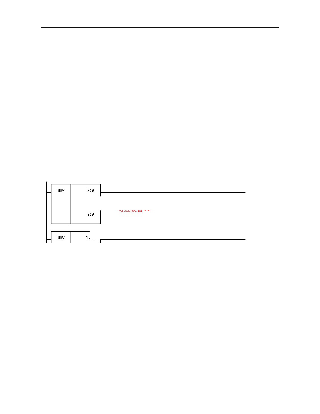
Parm511015, number of output point groups: 10
Device 12:
Parm512000, device name: IO_NET
Parm512012, initial group number of input point: 10
Parm512013, number of input point groups: 10
Parm512014, initial group number of output point: 10
Parm512015, number of output point groups: 10
Save modifications, power off and restart the machine tool.
8.2.2 Second Power-on and Commissioning Procedure
Note: Do not turn on the emergency stop button of the system. If conditions permit, it's best not to connect the
power line of traverse axis servo motor and power line of spindle servo motor.
1) Set PLC softdog
The system stipulates that the last group of input and output corresponding to the last group of IO_NET
identified by each IO box is the plc softdog.
Setup rules of softdog of MCP_NET are consistent with IO_NET. Input and output can be communicated
normally only when softdog is set correctly.
Thus, PLC softdog in this example is set as follows:
Correspond to device 12
Correspond to device 6
2) Set K parameter and fill out user IO comparison table
122
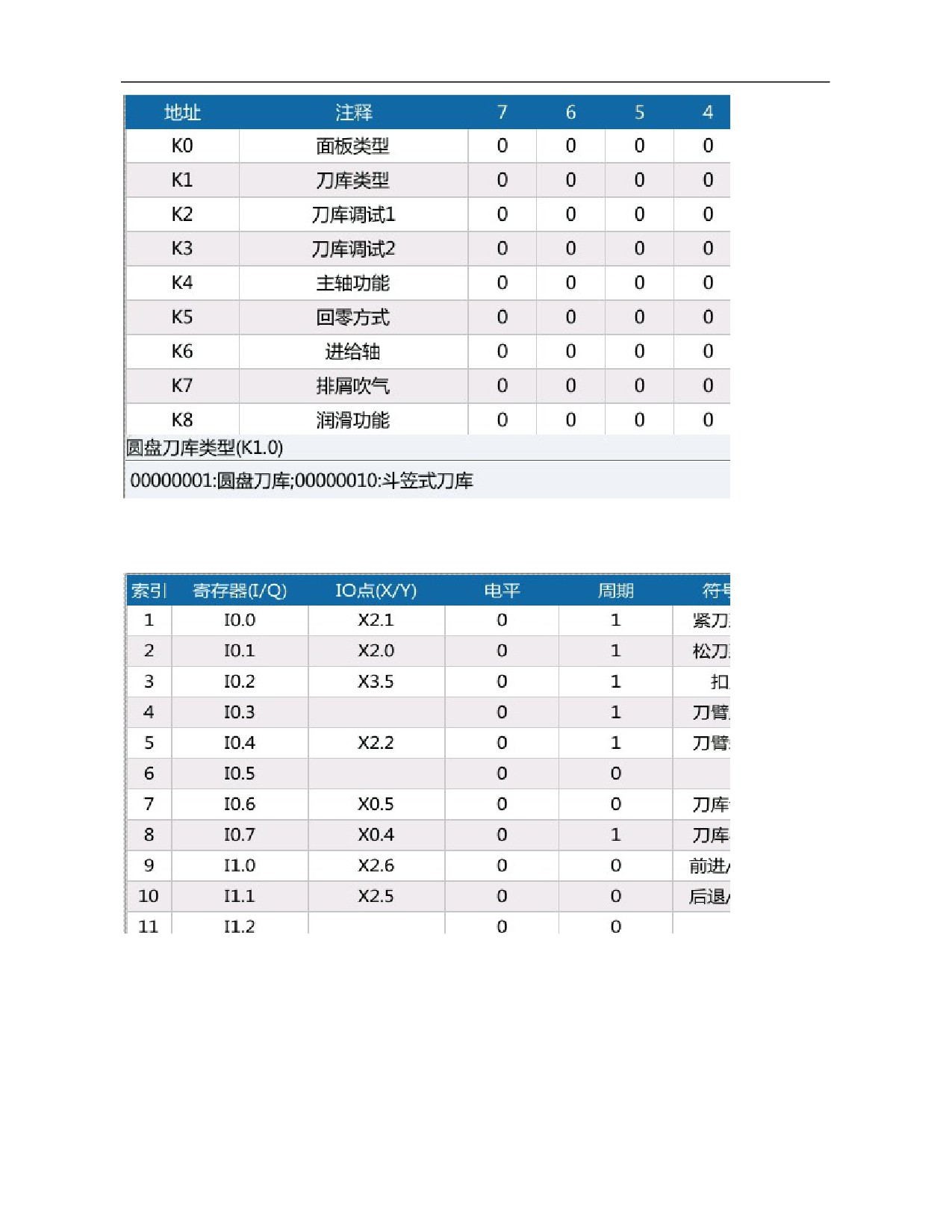
The system offers IQ comparison table and users can connect external input and output points according to
practical situation. During commissioning, fill external input and output switch value pointss in corresponding
IQ comparison table.
3) Set coordinate axis parameters
Set parameters of logical axes 0, 1, 2 and 5.
Parm10X004, numerator of electronic gear ratio (displacement) (um)
Parm10X005, denominator of electronic gear ratio [pulse]
Parm10X010, reference point return mode
Parm10X032, low speed jog speed (mm/min)
Parm10X033, high speed jog speed (mm/min)
Parm10X034, maximum rapid traverse speed (mm/min)
123
Parm10X035, maximum machining speed (mm/min)
Parm10X067, pulse count per revolution of axis (pulse)
Parm10X068, lead of guide screw (mm)
Parm10X090, encoder working mode
Parm10X094, encoder counting digits
Parm10X543, drive specification/motor type code
Note: If driver parameters cannot be read in coordinate axis parameters, please inspect STA-0 of corresponding
drive: Whether instruction interface option is 1 (NCUC bus).
Save modifications, power off and restart the machine tool.
8.2.3 Third Power-on and Commissioning Procedure
Note: Before power-on, connect the power line of traverse axis servo motor and power line of spindle servo
motor. Emergency stop is not enabled.
1) Check coordinate axis parameters
Check parameters of logical axes 0, 1, 2 and 5 on drive.
Logical axis 0, logical axis 1 and logical axis 2:
Parm10X517, maximum speed limit (1rad/min)
Parm10X522, pulse command input mode
Parm10X523, control mode selection
Parm10X524, number of servomotor pole pairs
Parm10X525, encoder type selection
Parm10X526. encoder zero offset
Parm10X586, motor rated current (0.01A)
Parm10X587, motor rated speed (1rad/min)
Logical axis 5:
Parm105517, maximum speed limit (1rad/min)
Parm105522, pulse command input mode
Parm105523, control mode selection
Parm105524, number of spindle motor pole pairs
Parm105525, resolution of spindle motor encoder
Parm105535, IM spindle motor rated speed (1rad/min)
Parm105553, IM motor rated current (0.1A)
After the above parameters have been checked, turn on the emergency stop button. After turning on the
emergency stop button, checj whether drive enable is normal and whether the brake of gravity axis is turned on.
2) Move the axis, set zero point, positive and negative limits
a. Move the axis at low speed and check whether the moving direction is correct. If the moving direction is
opposite, change the numerator of electronic gear ratio in logical axis parameters into a negative value. If it is a
negative value, change it into a positive value. Power off and restart to validate the modification.
b. Move the traverse axis to the position where zero point is set and set zero points of traverse axes through
automatic offset function. After setup, press and turn on the emergency stop button and observe whether actual
coordinates of the machine tool are cleared.
c. Set positive and negative soft limits of logical axes 0, 1 and 2, corresponding parameters are as follows:
parm10X006, positive software limit coordinate (mm)
parm10X007, negative software limit coordinate (mm)
124
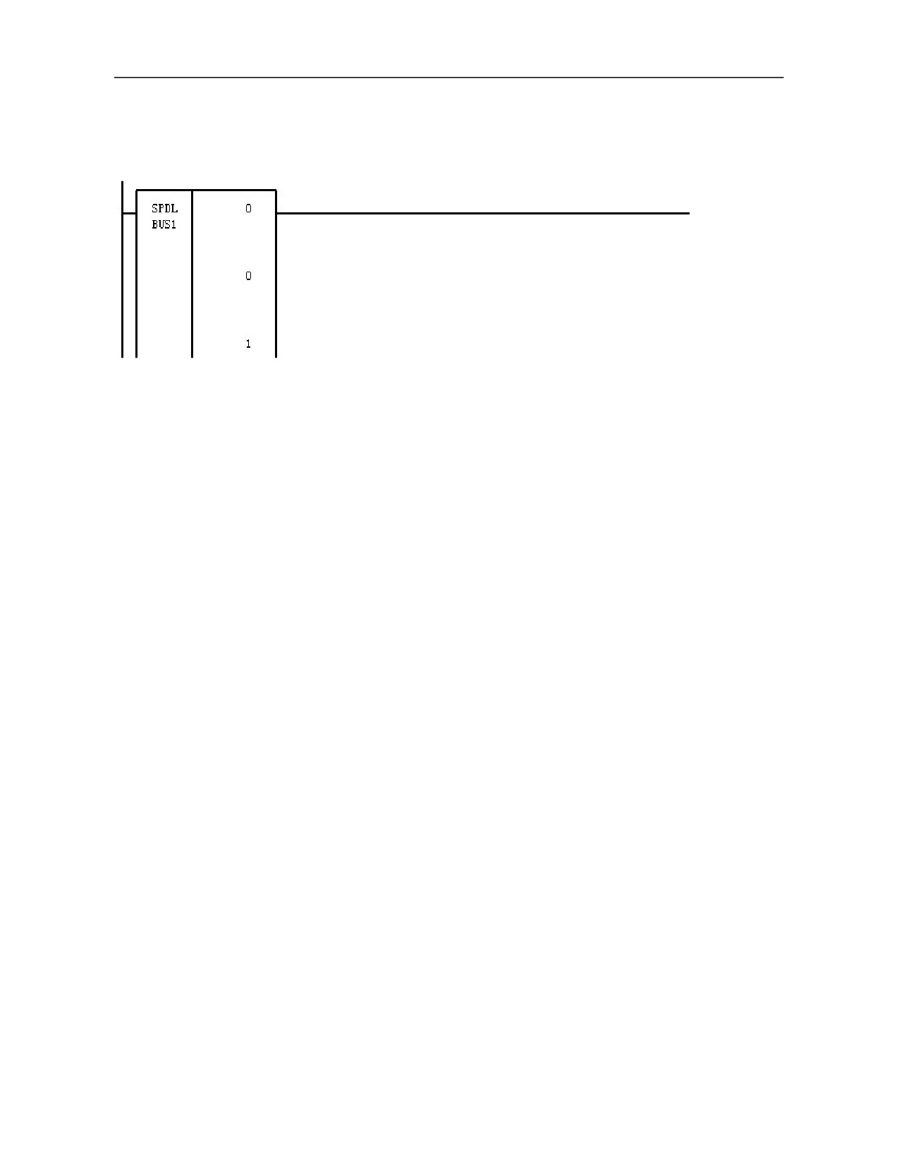
3) Spindle, set and test whether the spindle is started and stopped normally, whether the orientation is normal
and whether speed loop of spindle can be switched to position loop normally.
a. Start/stop of spindle
The servo spindle corresponds to the module of control spindle speed:
Corresponding machine user parameters:
Parm010359, maximum spindle speed
Parm010351, minimum spindle speed at gear 1
Parm010352, maximum spindle speed at gear 1
Parm010353, numerator of gear ratio at spindle gear 1
Parm010354, denominator of gear ratio at spindle gear 1
After setup, test whether the spindle is started and stopped correctly.
b. Test whether the spindle orientation is normal, and set the orientation position while commissioning
magazine.
c. Test whether speed loop of spindle can be switched to position loop normally.
This function requires to set spindle drive STA-8 (whether mode switch function is allowed) parameter as 1
(allowed). Power off and restart to validated the setting.
Generally MDI test is performed:
%1111
G109
M03 S500
G04 X2
M05
G108
G91G01C360F10000
G109
Run this program to check whether speed loop of the spindle can be switched to position loop normally.
125
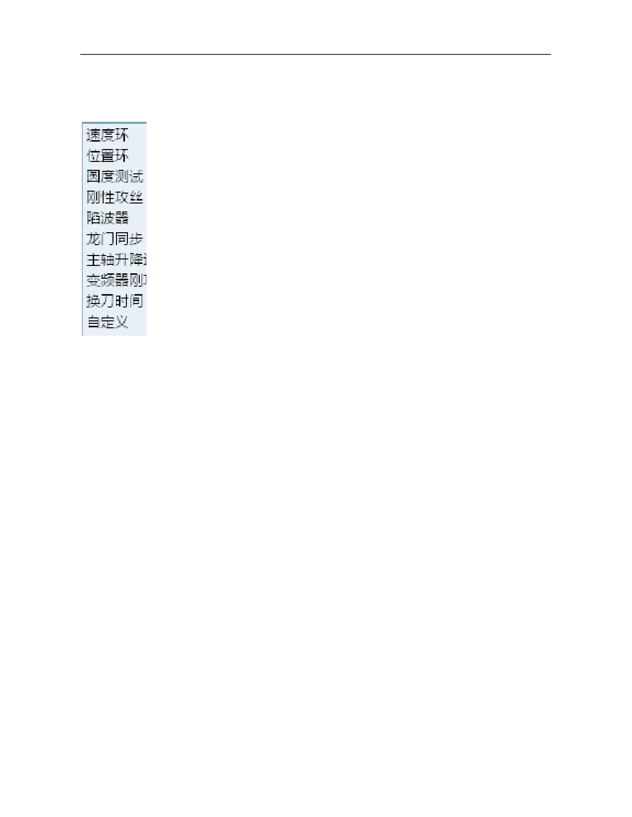
8.2.4 Servo Adjustment
Servo adjustment includes test feed axis characteristic adjustment, roundness compatibility
adjustment, rigid tapping synchronization adjustment, notch filter setup and spindle speed
adjustment.
8.2.5 Three-axis Burn-in
Check whether the machine tool is lubricated normally. Start the burn-in of the machine tool when lubrication
works normally.
8.2.6 Pitch Error Compensation
Pitch error compensation increases or decreases pulses of command value through parameters of the CNC
system to improve positional accuracy of machine tool.
8.2.7 Joint Debugging of Complete Machine
Complete functional debugging of magazine and other elements, system parameter setup optimization,
precutting, debugging report and final software backup.
8.2.8 Burn-in Test Of Complete Machine
Write burn-in test procedure and run the burn-in test program. After the burn-in is completed, complete the
commissioning of complete machine.
126
Annexed Table A Technical Specifications of HSV-160U Series Servo
Drive Unit and Motor Code
Technical specification of HSV-160U series AC servo drive unit
Short-time maximum
Continuous current
Maximum matching
current
Model
(A/30 min)
motor power
(A/1 min)
(Effective value)
(KW)
(Effective value)
HSV-160U-005
1.5
4.5
0.20
HSV-160U-007
2
6
0.40
HSV-160U-009
3
7.2
0.75
HSV-160U-010
4.8
7.2
0.75
HSV-160U-020
6.9
10.4
1.5
HSV-160U-030
9.6
14.4
2.3
HSV-160U-050
16.8
25.2
3.8
HSV-160U-075
24.8
37.3
5.5
HSV-160U-100
30.0
45.0
6.5
127
Huada motor LMBB parameter comparison table
Rated
Rated
Rated phase
Rated
Motor
Servomotor model
torque
speed
current
power
Drive unit
Code
(Nm)
(rpm)
(A)
(KW)
80ST-M01330LMBB
1.3
3000
2.8
0.40
HSV-160U-010
1000
110ST-M02420LMBB
2.4
2000
2.9
0.50
HSV-160U-010
1001
HSV-160U-010
1002
110ST-M02515LMBB
2.5
1500
3.5
0.40
HSV-160U-020
1102
HSV-160U-020
1103
80ST-M02430LMBB
2.4
3000
4.8
0.75
HSV-160U-030
1203
80ST-M03330LMBB
3.3
3000
6.2
1.0
HSV-160U-030
1204
110ST-M03215LMBB
3.2
1500
4.5
0.5
HSV-160U-020
1105
110ST-M05415LMBB
5.4
1500
6.5
0.85
HSV-160U-030
1206
110ST-M04820LMBB
4.8
2000
6.0
1.0
HSV-160U-030
1207
130ST-M03215LMBB
3.2
1500
4.5
0.5
HSV-160U-020
1208
130ST-M04820LMBB
4.8
2000
6.2
1.4
HSV-160U-030
1209
110ST-M06415LMBB
6.4
1500
8.0
1.0
HSV-160U-030
1210
130ST-M05415LMBB
5.4
1500
7.0
0.85
HSV-160U-030
1211
130ST-M06415LMBB
6.4
1500
8.0
1.0
HSV-160U-030
1212
130ST-M09615LMBB
9.6
1500
11.5
1.5
HSV-160U-050
1313
130ST-M07220LMBB
7.2
2000
9.5
1.5
HSV-160U-050
1314
130ST-M09620LMBB
9.6
2000
13.5
2.0
HSV-160U-075
1416
HSV-160U-075
1415
130ST-M14615LMBB
14.6
1500
16.5
2.3
HSV-160U-100
1515
HSV-160U-075
1417
130ST-M14320LMBB
14.3
2000
17.0
3.0
HSV-160U-100
1515
HSV-160U-075
1418
150ST-M14615LMBB
14.6
1500
20.0
2.3
HSV-160U-100
1518
HSV-160U-075
1419
150ST-M19115LMBB
19.1
1500
21.0
3.0
HSV-160U-100
1519
HSV-160U-075
1420
150ST-M14320LMBB
14.3
2000
20.0
3.0
HSV-160U-100
1520
128
Annexed Table B Technical Specifications of HSV-180U Series Servo
Drive Unit and Motor Code
Technical specification of HSV-180U series AC servo drive unit:
Drive unit model
HSV-180UD-035
HSV-180UD-050
HSV-180UD-075
Motor power (KW)
3.7KW
5.5KW
7.5KW
Rated output current (A)
12.5
16
23.5
Short-time maximum current (A)
22
28
42
Breaker (A)
25
32
40
Contactor (A)
18
25
32
Current (A)
10
15
20
Input AC electric
reactor
Inductance (mH)
1.4
0.93
0.7
Input filter (A)
10
15
20
Maximum brake current (A)
25
25
40
Resistance (Ω)
51Ω
51Ω
20Ω
Braking resistor
Power (W)
800W
800W
1200W
recommended
Quantity
1
1
1
Recommended value of main circuit
4
4
4
cable (mm2)
Drive unit model
HSV-180UD-090
HSV-180UD-100
HSV-180UD-150
Motor power (KW)
9KW
11KW
15KW
Rated output current (A)
30
32
47
Short-time maximum current (A)
52
56
84
Breaker (A)
63
63
100
Contactor (A)
40
40
63
Input AC electric
Current (A)
30
30
50
reactor
Inductance (mH)
0.47
0.47
0.28
Input filter (A)
30
30
50
Maximum braking current (A)
50
50
75
Resistance (Ω)
20Ω
33Ω
33Ω
Recommended
Power (W)
2000W
1500W
1500W
braking resistor
Quantity
1
2
2
Recommended value of main circuit
6
10
16
cable (mm2)
129
Drive unit model
HSV-180UD-035C
HSV-180UD-050C
HSV-180UD-075C
Motor power (KW)
3.7KW
5.5KW
7.5KW
Rated output current (A)
12.5
16
23.5
Short-time maximum current (A)
22
28
42
Breaker (A)
25
32
40
Contactor (A)
18
25
32
Current (A)
10
15
20
Input
AC
electric reactor
Inductance (mH)
1.4
0.93
0.7
Input filter (A)
10
15
20
Maximum braking current (A)
25
25
40
Resistance value (Ω)
51Ω
51Ω
20Ω
Recommended
Power (W)
800W
800W
1200W
braking resistor
Quantity
1
1
1
Recommended value of main circuit
4
4
4
cable (mm2)
Drive unit model
HSV-180UD-090C
HSV-180UD-100C
HSV-180UD-150C
Motor power (KW)
9KW
11KW
15KW
Rated output current (A)
30
32
47
Short-time maximum current (A)
52
56
84
Breaker (A)
63
63
100
Contactor (A)
40
40
63
Current (A)
30
30
50
Input
AC
electric reactor
Inductance (mH)
0.47
0.47
0.28
Input filter (A)
30
30
50
Maximum braking current (A)
50
50
75
Resistance (Ω)
20Ω
33Ω
33Ω
Recommended
Power (W)
2000W
1500W
1500W
braking resistor
Quantity
1
2
2
Recommended value of main circuit
6
10
16
cable (mm2)
130
Drive unit model
HSV-180UD-200
HSV-180UD-300
HSV-180UD-450
Motor power (KW)
30KW
37KW
51KW
Rated output current (A)
64.3
94
128
Short-time maximum current (A)
110
168
224
Breaker (A)
125
200
300
Contactor (A)
95
150
250
Current (A)
80
150
250
Input AC power
Electric reactor
Inductance (mH)
0.17
0.095
0.056
Input filter (A)
80
150
250
Maximum braking current (A)
100
100
150
Resistance (Ω)
30Ω
30Ω
30Ω
Recommended
Power (W)
2500W
2500W
2500W
braking resistor
Quantity
3
4
6
Recommended value of main circuit
35
70
95
cable (mm2)
Drive unit model
HSV-180U1D-100
HSV-180U1D-150
Motor power (KW)
11KW
15KW
Rated output current (A)
32
47
Short-time maximum current (A)
56
84
Breaker (A)
63
100
Contactor (A)
40
63
Current (A)
30
50
Input AC electric
reactor
Inductance (mH)
0.47
0.28
Input filter (A)
30
50
Maximum braking current (A)
50
75
Resistance (Ω)
33Ω
33Ω
Recommended
Power (W)
1500W
1500W
braking
resistance
Quantity
2
2
Recommended value of main circuit
10
16
cable (mm2)
131
Drive unit model
HSV-180U1D-200
HSV-180U1D-300
Motor power (KW)
30KW
37KW
Rated output current (A)
64.3
94
Short-time maximum current (A)
110
168
Breaker (A)
125
200
Contactor (A)
95
150
Current (A)
80
150
Input AC electric
reactor
Inductance (mH)
0.17
0.095
Input filter (A)
80
150
Maximum braking current (A)
100
100
Resistance (Ω)
30Ω
30Ω
Recommended
Power (W)
2500W
2500W
braking resistor
Quantity
3
4
Recommended value of main circuit
35
70
cable (mm2)
Specification and adaptability of Golden Age motor:
Rated
Phase
Motor
PA-43
Static torque
Servomotor model
Speed
current
Type
parameter
(Nm)
Matching drive unit
(rpm)
(A)
code
value
GK6073-6AC61
2000
11
5.6
00
0
HSV-180UD-035
HSV-180UD-035C
GK6080-6AC61
2000
16
6.8
01
1
GK6081-6AC61
2000
21
10
02
102
HSV-180UD-050
HSV-180UD-050C
GK6083-6AC61
2000
27
13.3
03
103
GK6085-6AC61
2000
33
16.5
04
204
HSV-180UD-075
HSV-180UD-075C
GK6087-6AC61
2000
37
18.5
05
205
HSV-180UD-090
GK6089-6AC61
2000
42
21
06
306
HSV-180UD-090C
HSV-180UD-090
GK6105-8AC61
2000
45
19.5
07
307
HSV-180UD-090C
HSV-180UD-090
GK6107-8AB61
1500
55
17.9
08
308
HSV-180UD-090C
HSV-180UD-100
GK6109-8AB61
1500
70
23.1
09
309
HSV-180UD-100C
HSV-180U1D-100
132
Specification and adaptability of Huada motor:
Rated
Rated
Rated
PA-43
Motor
Drive unit/
Servomotor type
speed
torque
current
parameter
type code
Overload multiple
(rpm)
(Nm)
(A)
value
HSV-180UD-035/8.8
110ST-M02515HMBB
1500
2.5
2.5
20
20
HSV-180UD-035C/8.8
HSV-180UD-035/8.8
110ST-M03215HMBB
1500
3.2
2.5
21
21
HSV-180UD-035C/8.8
HSV-180UD-035/6.3
110ST-M05415HMBB
1500
5.4
3.5
22
22
HSV-180UD-035C/6.3
HSV-180UD-035/5.5
110ST-M06415HMBB
1500
6.4
4.0
23
23
HSV-180UD-035C/5.5
HSV-180UD-035/8.8
110ST-M02420HMBB
2000
2.4
2.5
24
24
HSV-180UD-035C/8.8
HSV-180UD-035/6.3
110ST-M04820HMBB
2000
4.8
3.5
25
25
HSV-180UD-035C/6.3
HSV-180UD-035/8.8
130ST-M03215HMBB
1500
3.2
2.5
26
26
HSV-180UD-035C/8.8
HSV-180UD-035/5.8
130ST-M05415HMBB
1500
5.4
3.8
27
27
HSV-180UD-035C/5.8
HSV-180UD-035/5.5
130ST-M06415HMBB
1500
6.4
4.0
28
28
HSV-180UD-035C/5.5
HSV-180UD-035/3.7
130ST-M09615HMBB
1500
9.6
6.0
29
29
HSV-180UD-035C/3.7
HSV-180UD-035/2.3
130ST-M14615HMBB
1500
14.3
9.5
33
33
HSV-180UD-035C/2.3
HSV-180UD-035/6.3
130ST-M04820HMBB
2000
4.8
3.5
30
30
HSV-180UD-035C/6.3
HSV-180UD-035/4.4
130ST-M07220HMBB
2000
7.2
5.0
31
31
HSV-180UD-035C/4.4
HSV-180UD-035/2.9
130ST-M09620HMBB
2000
9.6
7.5
32
32
HSV-180UD-035C/2.9
HSV-180UD-035/2.3
130ST-M14320HMBB
2000
14.3
9.5
34
34
HSV-180UD-035C/2.3
HSV-180UD-035/2.5
150ST-M14615HMBB
1500
14.6
9.0
35
35
HSV-180UD-035C/2.5
HSV-180UD-050/2.4
150ST-M19115HMBB
1500
19.1
12.0
37
137
HSV-180UD-050C/2.4
HSV-180UD-075/3.2
150ST-M22315HMBB
1500
22.3
13.0
38
238
HSV-180UD-075C/3.2
HSV-180UD-075/2.5
150ST-M28715HMBB
1500
28.7
17.0
39
239
HSV-180UD-075C/2.5
HSV-180UD-035/2.5
150ST-M14320HMBB
2000
14.3
9.0
36
36
HSV-180UD-035C/2.5
133
HSV-180UD-075/2.9
150ST-M23920HMBB
2000
23.9
14.5
40
240
HSV-180UD-075C/2.9
HSV-180UD-075/2.7
150ST-M26320HMBB
2000
26.3
15.5
41
241
HSV-180UD-075C/2.7
HSV-180UD-050/2.4
180ST-M18020HMBB
2000
18.0
12.5
42
142
HSV-180UD-050C/2.4
HSV-180UD-075/2.8
180ST-M23020HMBB
2000
23.0
15.0
43
243
HSV-180UD-075C/2.8
HSV-180UD-075/2.4
180ST-M27020HMBB
2000
27.0
18.0
44
244
HSV-180UD-075C/2.4
HSV-180UD-090/2.4
180ST-M36015HMBB
1500
36.0
22.5
45
345
HSV-180UD-090C/2.4
HSV-180U1D-090/2.4
HSV-180UD-150/2.8
180ST-M45015HMBB
1500
45.0
30.0
46
446
HSV-180UD-150C/2.8
HSV-180U1D-150/2.8
HSV-180UD-150/2.5
180ST-M55015HMBB
1500
55.0
35.0
47
447
HSV-180UD-150C/2.5
HSV-180UID-150/2.5
134
Annexed Table C Technical Specifications of HSV-180US Series Spindle
Drive Unit and Motor Code
Specifications and model of spindle drive unit
Drive unit model
HSV-180US-035
HSV-180US-050
HSV-180US-075
Motor power (KW)
3.7KW
5.5KW
5.5KW
7.5KW
7.5KW
11KW
Rated output current (A)
16.8
21.9
31.4
Short-time maximum current (A)
22
28
42
Breaker (A)
25
32
32
40
40
63
Contactor (A)
18
25
25
32
32
40
Input AC
Current (A)
10
15
15
20
20
30
Electric reactor
Inductance (mH)
1.4
0.93
0.93
0.7
0.7
0.47
Input filter (A)
10
15
15
20
20
30
Maximum braking current (A)
25
25
40
Resistance (Ω)
51Ω
51Ω
20Ω
Recommended
Power (W)
1100W
1100W
2000W
braking resistor
Quantity
1
1
1
Recommended value of main circuit
4
4
4
4
4
10
cable (mm2)
Drive unit model
HSV-180US-100
HSV-180US-150
Motor power (KW)
11KW
15KW
18.5KW
22KW
Rated output current (A)
43.8
62.8
Short-time maximum current (A)
56
84
Breaker (A)
63
63
100
100
Contactor (A)
40
50
63
80
Input AC electric
Current (A)
30
40
50
60
reactor
Inductance (mH)
0.47
0.35
0.28
0.24
Input filter (A)
30
40
50
65
Maximum braking current (A)
50
75
Resistance (Ω)
33Ω
20Ω
Recommended
Power (W)
1500W
2000W
braking resistor
Quantity
2
2
Recommended value of main circuit cable
10
16
16
25
(mm2)
135
Drive unit model
HSV-180US-200
HSV-180US-300
HSV-180US-450
Motor power (KW)
30KW
37KW
51KW
75KW
Rated output current (A)
85.7
125
170
Short-time maximum current (A)
110
168
224
Breaker (A)
125
160
200
400
Contactor (A)
95
115
150
250
Current (A)
80
90
150
250
Input AC electric
reactor
Inductance (mH)
0.17
0.16
0.095
0.056
Input filter (A)
80
100
150
250
Maximum brake current (A)
100
100
150
Resistance (Ω)
30Ω
30Ω
30Ω
Recommended
Power (W)
2500W
2500W
2500W
braking resistor
Quantity
3
4
6
Recommended value of main circuit cable
35
70
95
(mm2)
Drive unit model
HSV-180US-035R
HSV-180US-050R
HSV-180US-075R
Motor power (KW)
3.7KW
5.5KW
5.5KW
7.5KW
7.5KW
11KW
Rated output current (A)
16.8
21.9
31.4
Short-time maximum current (A)
22
28
42
Breaker (A)
25
32
32
40
40
63
Contactor (A)
18
25
25
32
32
40
Current (A)
10
15
15
20
20
30
Input AC
electric reactor
Inductance (mH)
1.4
0.93
0.93
0.7
0.7
0.47
Input filter (A)
10
15
15
20
20
30
Maximum braking current (A)
25
25
40
Resistance (Ω)
51Ω
51Ω
20Ω
Recommended
Power (W)
1100W
1100W
2000W
braking resistor
Quantity
1
1
1
Recommended value of main circuit cable
4
4
4
4
4
10
(mm2)
136
Drive unit model
HSV-180US-100R
HSV-180US-150R
Motor power (KW)
11KW
15KW
18.5KW
22KW
Rated output current (A)
43.8
62.8
Short-time maximum current (A)
56
84
Breaker (A)
63
63
100
100
Contactor (A)
40
50
63
80
Current (A)
30
40
50
60
Input AC
Electric reactor
Inductance (mH)
0.47
0.35
0.28
0.24
Input filter (A)
30
40
50
65
Maximum braking current (A)
50
75
Resistance (Ω)
33Ω
20Ω
Recommended
Power (W)
1500W
2000W
braking resistor
Quantity
2
2
Recommended value of main circuit cable
10
16
16
25
(mm2)
Drive unit model
HSV-180U1S-100
HSV-180U1S-150
Motor power (KW)
11KW
15KW
18.5KW
22KW
Rated output current (A)
43.8
62.8
Short-time maximum current (A)
56
84
Breaker (A)
63
63
100
100
Contactor (A)
40
50
63
80
Current (A)
30
40
50
60
Input AC electric
reactor
Inductance (mH)
0.47
0.35
0.28
0.24
Input filter (A)
30
40
50
65
Maximum braking current (A)
50
75
Resistance (Ω)
33Ω
20Ω
Recommended
Power (W)
1500W
2000W
braking resistance
Quantity
2
2
Recommended value of main circuit cable
10
16
16
25
(mm2)
137
Drive unit model
HSV-180U1S-200
HSV-180U1S-300
Motor power (KW)
30KW
37KW
51KW
Rated output current (A)
85.7
125
Short-time maximum current (A)
110
168
Breaker (A)
125
160
200
Contactor (A)
95
115
150
Current (A)
80
90
150
Input AC power
Electric reactor
Inductance (mH)
0.17
0.16
0.095
Input filter (A)
80
100
150
Maximum brake current (A)
100
100
Resistance (Ω)
30Ω
30Ω
Recommended
Power (W)
2500W
2500W
braking resistance
Quantity
3
4
Recommended value of main circuit cable
35
70
(mm2)
138

Code of common Golden Age asynchronous spindle motor
Motor
Rated
Rated
Rated
PA-59
type
Motor model
power
torque
current
Drive unit
Parameter
code
(KW)
(Nm)
(A)
value
HSV-180US-035
00
GM7101-4SB61
3.7
23.6
10
0
HSV-180US-035R
HSV-180US-035
1
HSV-180US-035R
01
5.5
35
13
GM7103-4SB61
HSV-180US-050
101
HSV-180US-050R
HSV-180US-050
102
HSV-180US-050R
02
7.5
47.8
18.8
GM7105-4SB61
HSV-180US-075
202
HSV-180US-075R
HSV-180US-075
203
HSV-180US-075R
03
11
70
25
HSV-180US-100
GM7109-4SB61
HSV-180US-100R
303
HSV-180U1S-100
HSV-180US-100
HSV-180US-100R
304
HSV-180U1S-100
04
15
95.5
34
GM7133-4SB61
HSV-180US-150
HSV-180US-150R
404
HSV-180U1S-150
05
GM7135-4SB61
18.5
117.8
42
HSV-180US-150
405
HSV-180US-150R
06
GM7137-4SB61
22
140.1
57
HSV-180U1S-150
406
139
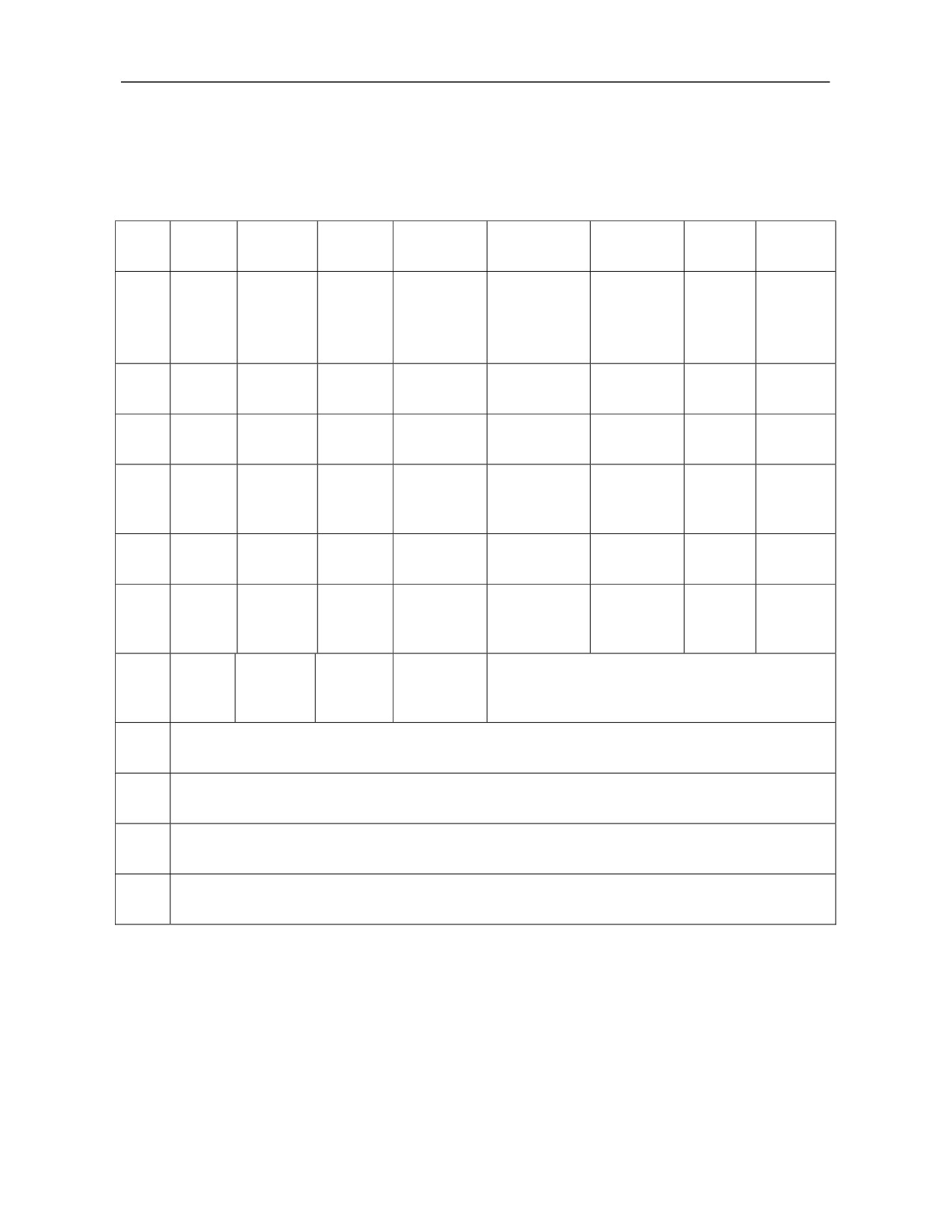
Annexed Table D HNC-8 System MCP Panel Input/Output
808D panel of milling system
0
1
2
3
4
5
6
7
Rapid
Rapid
Rapid
Referenc
traverse
traverse
traverse
Block
X480
Jog
MPG
e point
Dryrun
override
override
override
skip
return
-10%
100%
+10%
Single
Spindle
Spindle
3-axis
Optional
Machine
X481
Auto
MDI
block
Orientation
Jog
home
stop
lock
Cooling
Cooling
Spindle
Spindle
Spindle
Protectiv
MPG
X482
Air blow
auto
manual
CW
Stop
CCW
e door
precut
Tool
Chip
Chip
Next
X483
+4TH
+Z
-Y
Clamping/rel
Tool change
removal
removal
tool
ease
CW
CCW
Rapid
Magazine
Tool arm
Back
Machine
X484
+X
-X
F1
traverse
debug
CW
flush
light
Overtrav
Magazine
Magazine
Lubricatio
X485
+Y
-Z
-4TH
F2
el
CW
CCW
n
Release
Program
Cycle
Feed
X486
lock
Feedrate override
Start
Hold
X487
Feedrate override
X488
Spindle system
X496
Incremental pulses per cycle of handwheel
X497
Emergency stop, MPG axis selection and MPG override
140
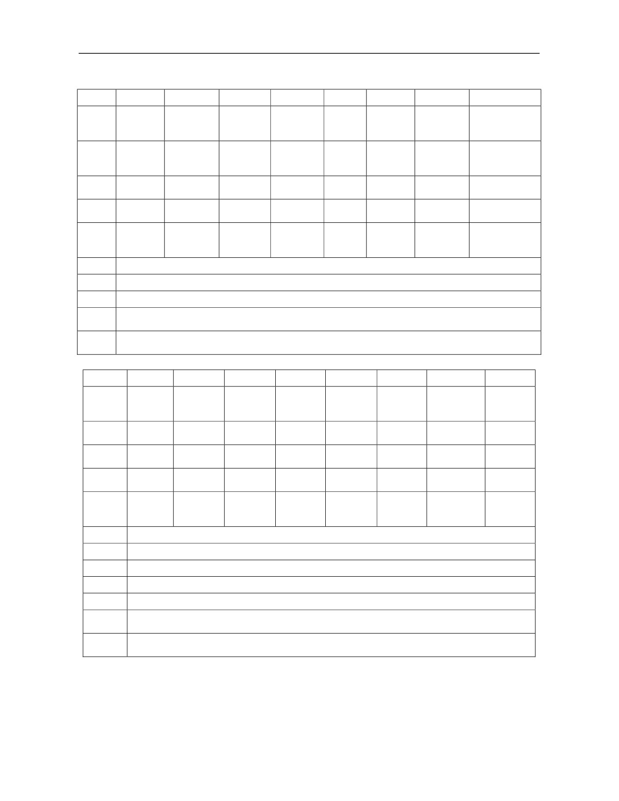
818D panel of milling system with MPG
0
1
2
3
4
5
6
7
Reference
Magazine
Magazine
Magazine
X480
Jog
Handwheel
point
Auto
MDI
debugging
CW
CCW
return
Magazine
Single
Block
X481
home
+4TH
+Z
-Y
Dryrun
X1
block
skip
Fast
Optional
MPG
X482
X10
X100
+X
-X
Machine lock
forward
stop
precut
Lubricatio
Protective
3-axis
Spindle
Spindle
X483
+Y
-Z
-4TH
n
door
home
CW
stop
Spindle
Machine
Tool return/
Cycle
Feed
Program
X484
orientatio
Cooling
light
install
start
hold
lock
n
X486
Feedrate override
X487
Spindle system
X494
Incremental pulses per cycle of handwheel
Y486
Magazine tool number is displayed by Nixie tube
Y487
Y488
Spindle tool number is displayed by Nixie tube
Y489
818D panel of milling system without handwheel
0
1
2
3
4
5
6
7
Reference
Magazine
Magazine
Magazine
X480
Jog
Handwheel
point
Auto
MDI
CW
CCW
debugging
return
Magazine
Single
Program
X481
+4TH
+Z
-Y
Dryrun
Shortcut
home
block
Skip
Rapid
Optional
Machine
X482
F1
F2
+X
-X
MPG precut
traverse
stop
lock
Lubricati
Protective
3-axis
Spindle
Spindle
X483
+Y
-Z
-4TH
on
door
home
CW
stop
Spindle
Tool
Machine
Cycle
Feed
Program
X484
orientatio
Cooling
return/inst
light
start
hold
lock
n
all
X486
Rapid traverse override
X487
Spindle system
X488
Feedrate override
X496
Incremental pulses per cycle of handwheel
X497
Emergency stop, MPGaxis selection and MPG override
Y486
Magazine tool number is displayed by Nixie tube
Y487
Y488
Spindle tool number is displayed by Nixie tube
Y489
141
Annexed Table E Detailed List of HNC-8 F-G Registers
Axis status word:
Each axis is configured with 80 status words. Each word has 16 bytes, the first line represents 0-7 bits and the
second line represents 8-15 bits. When axis status word is used, logical number offset of axis should be added.
【F0.0】Axis is moving: It is 1 when axes are moving and 0 when axes do not move.
【F0.1】First step of reference point return: It is 1 when an axis returns to the reference point and does not touch
the block; otherwise, it is 0.
【F0.2】Second step of reference point return: It is 1 while looking for Z pulse; otherwise, it is 0.
【F0.3】Reference point return fails: It is 1 when reference point return of axis fails; otherwise, it is 0.
【F0.4】Reference point return succeeds: It is 1 when reference point return of axis succeeds; otherwise, it is 0.
【F0.5】Salve axis is homing.
【F0.6】check of slave axis zero is completed.
【F0.7】Following state of slave axis has been relieved.
【F0.8】 Confirmation of the first reference point: It is 1 when the axis is at the first reference point; otherwise,
it is 0.
【F0.9】Confirmation of the second reference point: It is 1 when the axis is at the second reference point;
otherwise, it is 0.
【F0.10】 Confirmation of the third reference point: It is 1 when the axis is at the third reference point;
otherwise, it is 0.
【F0.11】Confirmation of the fourth reference point: It is 1 when the axis is at the fourth reference point;
otherwise, it is 0.
【F0.12】Axis overload mark: It is 1 when the axis is overloaded; otherwise, it is 0.
【F0.13】Axis parameters are validated.
【F0.14】Axis is locked.
【F0.15】Axis has been relocated.
【F1.0】PMC control enable. It is 1 when PMC control is enabled; otherwise, it is 0.
【F1.1】Feed spindle mode. It is 1 under position mode and 0 under speed mode.
【F1.5】Feed spindle has been oriented.
【F1.6】Zero speed of feed spindle.
【F1.7】Arrival of feed spindle speed.
【F2.0】 It is 1 when reference point return Z pulse signal is captured; otherwise, it is 0.
【F2.3】The second encoder Z pulse is captured. It is mainly used for reference point return of distance-coded
grating ruler.
【F2.6】Zero position is captured. It is mainly used for spindle. It is set as 1 when the Z pulse is touched during
spindle rotation. It should be 1 during CS switching.
【F2.8】It is 1 when bus servo is prepared; otherwise, it is 0.
【F2.9】It is 1 when the servo is under position control mode; otherwise, it is 0.
【F2.10】 It is 1 when the servo is under speed control mode; otherwise, it is 0.
【F2.11】 It is 1 when the servo is under torque control mode; otherwise, it is 0.
【F2.14】It is 1 for the spindle speed arrival; otherwise, it is 0.
【F2.15】Zero speed of spindle: It is 1 when the spindle stops; otherwise, it is 0.
【F3.0】It is 1 when the servo is normal.
142
【F3.1】It is 1 when the servo gives an alarm.
【F3.2】It is 1 when the servo gives a prompt message.
【F3.8】Orientation of spindle is completed: It is 1 after orientation of spindle is
set, the spindle
starts
orientation and the servo gives feedback of spindle orientation signal; otherwise, it is 0.
【F4】Channel number of axis.
【F5】Number of slave axes
【F[6/7]】Command increment outputted in real time, coordinates of motor.
【F[8/9]】Command position outputted in real time, coordinates of motor.
【F[12/13]】Output command pulse position, unit: pulse.
【F[16/17]】Output command pulse increment, unit: pulse.
【F[18/19]】Output command torque.
【F[20/21]】Actual position of encoder 1.
【F[24/25]】Actual position of encoder 2.
【F[28/29]】Machine command position.
【F[32/33]】Machine command position.
【F[36/37]】Axis alarm.
【F36.2】Press positive limit block.
【F36.3】Press negative limit block.
【F36.4】Actual speed is overspeed.
【F36.6】Overspeed.
【F36.7】Super acceleration.
【F36.8】Z pulse cannot be found.
【F36.9】Disconnected.
【F36.10】Not return to the reference point.
【F36.11】Synchronous position out-of-tolerance.
【F36.12】Slave axis zero check failed.
【F36.13】Synchronous speed out-of-tolerance.
【F37.0】Exceed positive limit of travel.
【F37.2】Exceed negative limit of travel.
【F37.2】Acceleration mismatches maximum speed.
【F[38/39]】Axis prompt.
【F38.0】Exceed maximum compensation rate.
【F38.1】Exceed maximum compensation value.
【F38.2】Zero offset parameter is too small.
【F38.4】Software limit value is too large.
【F38.5】The second software limit value is too large.
【F38.6】Absolute encoder cycle digits are illegal
【F38.7】Position overflow.
【F38.8】The target point is beyond the positive limit.
【F38.9】The target point is beyond the negative limit.
【F38.10】Z pulse mask angle needs to be adjusted.
【F38.11】Reference position needs to be adjusted.
【F38.12】Tracking error is too large.
【F[70]】Current mode of axis. When the axis mode status is 102, handwheel interrupt mode is valid. When the
axis mode status is 103, PMC axis mode is valid.
【F[474]】Target gear stage of spindle. BIT0-BIT3 represent gear 1-4 respectively.
143
Axis control word
【G0.0】Positive limit switch of axis.
【G0.1】Negative limit switch of axis.
【G0.2】Positive movement of axis is disabled.
【G0.3】Negative movement of axis is disabled.
【G0.4】Start to set reference point return.
【G0.5】Set reference point return start.
【G0.6】Set axis lock.
【G0.7】Set axis enable.
【G0.11】Set to release following function of slave axis.
【G0.15】Reset of single axis.
【G1.0】Absolute movement enable of PMC axis.
【G1.1】Relative movement enable of PMC axis.
【G1.2】The second software limit enable.
【G1.3】Extended software limit enable.
【G1.5】Feed spindle orientation.
【G1.6】Feed spindle clockwise rotation.
【G1.7】Feed spindle counter clockwise rotation.
【G1.12】Response mark of PLC to spindle C/S switching.
【G2.0】Capture zero pulse.
【G2.1】Wait for zero pulse.
【G2.2】Disable zero pulse search function.
【G2.3】Capture zero pulse of the second encoder.
【G2.8】Servo parameter switching 0: Default parameter 1: Switch to the second set of parameters
【G2.9】Switch to position control mode
【G2.10】Switch to speed control mode.
【G2.11】Switch to torque control mode.
【G2.12】Start spindle orientation.
【G2.14】Select an orientation point for spindle orientation: 0 refers to the first orientation point and 1 refers to
the second orientation point.
【G2.15】Enable current-limiting function of servo axis.
【G3.0】Servo enable switch.
【G3.1】Reset servo, clear servo alarm.
【G4】Jog mark of axis. The mark is valid when the axis in Jog, reference point return, and rotation.
【G5】Increment mark of axis. The mark is valid during incremental movement of axis.
【G[6/7]】Jog speed, 0, stop; 1, jog speed in parameters; 2, rapid traverse seed; >2, user-defined speed.
【G8】Incremental magnification.
【G9】Handwheel magnification.
【G[10/11]】Pulse count of handwheel.
【G[12/13]】Axis feedback position, unit: pulse.
【G[16/17]】Axis feedback position 2, unit: pulse.
【G[20/21]】Axis feedback increment, unit: pulse.
【G[22/23]】Axis feedback increment 2, unit: pulse.
【G[24/25]】Axis feedback torque current.
144
【G[26/27]】Axis feedback tracking error, unit: pulse.
【G[28/29]】Counter value of encoder 1.
【G[32/33]】Counter value of encoder 2.
【G[36/37]】Real-time compensation value.
【G[38/39]】Sampling time stamp.
【G[48/49]】Absolute movement position of PMC axis.
【G[52/53]】Incremental movement amount of PMC axis.
【G[56/57]】Servo alarm number.
【G[58/59]】Servo prompt number.
【G60】Switching of axis control mode.
When the axis control mode is set to 102, request the axis control mode to switch to the handwheel interrupt
mode. When set to 0, exit the handwheel interrupt mode. When the axis control mode is set to 103, the axis
control mode is requested to switch to the PMC axis mode. When set to 0, exit PMC axis mode.
【G61】PMC axis override value.
【G62.0】PMC axis stop.
【G62.1】Clear handwheel interrupt amount.
【G462.9】Enable spindle gear change speed.
When this signal is valid, the motor runs a the speed set by "Motor speed during spindle gear change".
【G464】Current gear stage of spindle. BIT0-BIT3 represent gear 1-4 respectively.
Channel status word
【F2560.0 -F2560.3】
0: Reset mode 1: Auto mode 2: Jog mode
3: Incremental mode 4: MPG mode 5: Reference point return mode
6: PMC mode 7: Single block mode 8: MDI mode
【F2560.4】Feed hold: The channel is at feed hold state.
【F2560.5】Cycle start: The channel is at cycle start state.
【F2560.7】Under user motion intervention.
【F2560.9】Thread cutting: The channel is at thread cutting state and feed hold is not allowed.
【F2560.12】Channel reset: When channel is reset or reset key on the panel is pressed, channel reset is valid
until channel reset response is set.
【F2560.13】Channel is being reset.
【F2560.14】Z pulse search of reference point return is in progress, mode switching is not allowed.
【F2561.0】Program selected, set by interpreter.
【F2561.1】Program start, set by channel control.
【F2561.2】Program completed, set by channel control.
【F2561.3】G28/G31 and other interrupt commands are completed.
【F2561.4】Interrupt command is skipped.
【F2561.5】Wait command is completed.
【F2561.6】Program rerun reset.
【F2561.7】Any line request mark.
【F2561.8】Channel loading breakpoint.
【F2562.8】Tool selection mark.
【F2562.9】Tool offset mark [T includes tool offset number].
【F2562.10】PLC indexing command mark.
【F2562.11】Spindle constant linear speed.
145
【F2562.12】 Spindle 0 of channel 0 has S command.
【F2569】Tool offset number.
【F[2570/2571】The first S command, unit: 0.001r/min.
【F[2572/2573】The second S command, unit: 0.001r/min.
【F[2574/2575】The third S command, unit: 0.001r/min.
【F[2576/2577】The fourth S command, unit: 0.001r/min.
【F2578】G31 number of current wait signal.
【F[2581/2589]】Numbers of 9 axes in channel.
【F[2590/2593]】Number of 4 spindles in channel.
【F[2594/2595]】Syntax error alarm number.
【F[2596/2599]】Channel alarm number.
【F[2600/2603]】Channel prompt number.
【F[2604/2607]】User output.
【F[2608/2615]】M codes running in the channel, no more than 8 codes.
【F2616】T codes running in the channel.
【F2617】B codes running in the channel.
【F2637.1】Manually subprogram-calling mark: 1: Subprogram is being called manually; otherwise, it is 0.
Channel control word
【G2560.3】 Single block mode: When MDI key is on the MCP panel, set single block mode of channel and
hold state.
【G2560.4】Feed hold: Set feed hold of channel.
【G2560.5】Cycle start: Set cycle start of channel.
【G2560.6】Dryrun: Set dryrun state of channel.
【G2560.9】Reset response: Set reset response after channel is reset.
【G2560.11】Emergency stop: Set emergency stop of channel.
【G2560.12】Clear buffer of channel.
【G2560.13】Reset: Set reset of channel.
【G2560.14】Recover data of channel.
【G2560.15】Save data of channel.
【G2561.0】Start interpreter.
【G2561.1】The program reruns the second step.
【G2561.2】Block skip: Set block-skip state of channel.
【G2561.3】Optional stop: Set optional stop state of channel.
【G2561.4】Reset interpreter.
【G2561.5】The program reruns.
【G2561.6】Any line of program runs.
【G2561.7】Recover data of interpreter.
【G2561.8】Save data of interpreter.
【G2561.10】User motion control.
【G2561.11】External interrupt.
【G2561.12】Enable handwheel interrupt function.
【G2561.14】Program modification mark.
【G2562.0】Gear change completion response.
【G2562.10】Spindle speed check.
【G2562.11】Channel MST lock.
146
【G2562.12】There is no spindle in channel, rotation speed arrival needs not to be checked.
【G2562.13】Spindle speed arrival of channel.
【G2620.0】Auto: Set channel to auto mode.
【G2620.1】Single block/MDI: When MDI key is on the NC panel, set single block mode of channel. When
MDI key is on the MCP panel, set MDI mode of channel.
【G2620.2】Jog: Set channel jog mode.
【G2620.3】Increment: Set channel to incremental mode.
【G2620.4】Reference point return: Set channel to reference point return mode.
【G2620.5】MPG: Set channel to handwheel mode of channel.
【G2620.6】PMC: Set channel to PMC mode.
【G2620.7】Panel enable: To use registers with ◆, panel enable must be set as 1.
【G2620.8-G2620.9】Increment magnification: Increment magnification occupies 2 bits. 00 represents x1, 01
represents x10; 10 represents x100; 11 represents x1000.
【G2620.10】Rapid traverse: Set movement mode of all axes in channel 0 as rapid traverse mode.
【G2621.0-2621.7】Handwheel axis option: Each axis of handwheel occupies 4 bits and a 4-bit figure represents
current axis option. e.g.: If 4 bits of axis option is 0000, it represents X axis; 0001 represents Y axis; 0010
represents Z axis.
【G2621.8-G2621.11】Handwheel magnification: Every magnification of handwheel occupies 2 bits and a 2-bit
figure represents current magnification. 00 represents x1; 01 represents x10; 10 represents x10; 11 represents
x1000.
【G2621.12】 Handwheel 1 enable: Handwheel 1 can be used only after handwheel 1 enable is set.
【G2622】-【G2623】When the axis requires jog, incremental, reference point return movement or spindle
CW/CCW rotation, only the axis motion control register needs to be set. If positive/negative movement mark of
axis is set at the same time, the axis will not move. Under jog mode, if positive/negative movement mark of axis
is set, the axis will move in positive/negative direction manually. Under incremental mode, if an effective period
of positive/negative movement mark of axis (rising edge) is set, the axis will move a certain distance. Under
reference point return mode, if positive/negative movement sign of axis is set, the axis will start the reference
point return (under distance-coded reference point return mode, positive/negative movement mark of axis
represents reference point return direction of feed axis). Under speed control mode, if positive/negative
movement sign of axis is set, the axis will rotate in positive/negative direction.
【G2626.0】Channel alarm bit, the channel gives an alarm when it is set as 1.
【G2626.1】Channel prompt bit, the channel gives a prompt message when it is set as 1.
【G2562.10】Spindle fluctuation detection, spindle fluctuation starts to be checked when it is set as 1.
【G2563】Tool number displayed in the channel.
【G2564】Feed override in the channel.
【G2565】Rapid traverse override in the channel.
【G[2566/2569】 4 spindle override in the channel.
【G[2570/2571]】Spindle 1 output command, override and gear ratio have been calculated. Analog spindle
represents the outputted DA value.
【G[2572/2573]】Spindle 2 output command.
【G[2574/2575]】Spindle 3 output command.
【G[2576/2577]】Spindle 4 output command.
【G2578.0】Control of workpiece coordinate system.
【G2578.1】Control of imaginary axis coordinate system.
【G2578.8】Initialization of tool coordinate system control.
【G2578.9】Running of tool coordinate system control.
147
【G2578.0】Control of workpiece coordinate system.
【G2579】Count of workpiece.
【G2580】Internal inhibition mask.
【G2581】External inhibition mask.
【G2582】G31 number when measurement is interrupted.
【G[2608/2615]】Response of 8 M codes in the channel.
【G2616】Response of T codes in the channel.
【G[2628/2629]】Output command speed of spindle 1. Spindle fluctuation is detected according to deviation
between the actual speed and it.
【G[2630/2631]】Output command speed of spindle 2.
【G[2632/2633]】Output command speed of spindle 3.
【G[2634/2635]】Output command speed of spindle 4.
【F2961】Channel shield status word.
【G2637】Manual call of subprogram.
【F2978】Active channel number of system.
【G2961】Channel shield request word.
【G2978】Active channel request of system.
【G2960.0】The first emergency release mark. It is set as 1 after emergency stop is released for the first time.
【G2960.6】Program lock. Program can be edited only when it is set as 1.
【G2963】 Device 0-device 4 in device interface parameters.
0: Devices 0-3 are devices reserved by the system;
1: Devices 0-4 are imaginary axes which can be allocated to system axis;
2: Mix imaginary axis and virtual MCP panel. Devices 0-3 are imaginary axes which can be allocated to system
axes and used during simulation running. Device 4 is the imaginary MCP, when it is enabled the keyboard can
be used as MCP function. This function can be used if there is no MCP panel;
4: Imaginary pulse axis drive. Devices 0-3 are imaginary axes and this function is used when pulse axis
interface is used.
148
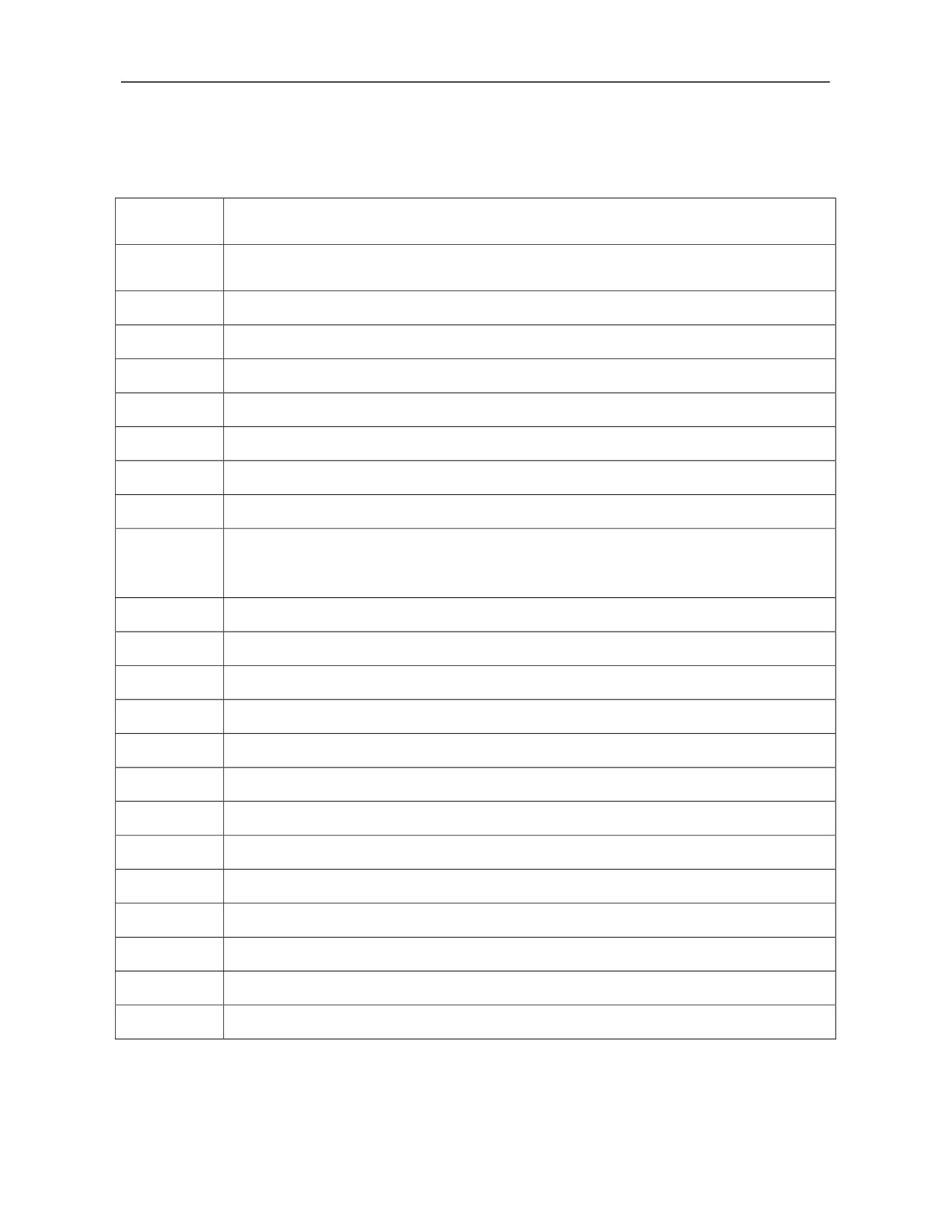
Annexed Table F Detailed List of HNC-8 User PLC Events
User PLC
Usage
event number
After hardware reset is completed, software processes some initialization contents. e.g.: Load the
102
previously loaded program, etc.
103
PLC notifies HMI, PLC modifies B register, HMI saves B register during power failure
104
Channel switching request when there are multiple channels
105
Channel switching shielding when there are multiple channels
106
Dedicated for DMTG
107
Dedicated for DMTG
108
Dedicated for DMTG
109
Dedicated for DMTG
One-click offset event. Modify coordinate system, tool offset and other data during feed hold.
110
After one-click offset, the system executes rerun operation automatically so that the modified
data is validated immediately. (For special use)
115
Reset function triggered by PLC, which equals to pressing Reset key
116
Automatically load digital program name designated by channel variable 1131
117
Dedicated for glass machine
118
Dedicated for glass machine
119
Notify HMI that MCP key is pressed for timing of "Screen protection" function
120
When multiple channels are reset, PLC has selected set channel number events
121
PLC gives a message of permission switching
122
RFID reads data of electronic label to CNC
123
RFID writes CNC data to electronic label
124
Channel 0 changes tool in tool life management
125
Channel 1 changes in during tool life management
126
Channel 2 changes tool in tool life management
127
Channel 3 changes tool during tool life management
149