HV100 Series Frequency Inverter. User Manual (V4.0) - page 7
LED ten bits: Over modulation selection
0: Invalid
1: Valid
The over-modulation function means that the inverter increases the output voltage by adjusting the utilization rate of
the bus voltage. When the over-modulation is effective, the output harmonics will increase. If long-term low-voltage and
heavy-load operation or high-frequency (over 50HZ) operating torque is insufficient, this function can be turned on.
LED hundred bits: dead zone compensation selection
0:Invalid
1: Valid
If the selection is valid, under all control modes, full frequency dead zone compensation. This function is mainly used
for factory debugging, and it is not recommended for customers to set it.
LED thousand bits: Vibration suppression options
0: Invalid
1: Oscillation suppression mode 1
2: Oscillation suppression mode 2
3: Oscillation suppression mode 3
When mode 1 works, the PWM mode is forced to be five segment; When mode 2 works, the original mode remains
unchanged, and the two modes can be adjusted by the oscillation suppression coefficient (12.27).
In special occasions, if the first two modes cannot suppress the oscillation, use mode 3, and adjust the parameters
12.27
(oscillation suppression coefficient) and 12.28 (oscillation suppression voltage) together.
Oscillation suppression starting frequency
12.20
0.00~300.00
Model setting
Magnetic flux braking selection
12.21
0~100
0
This parameter is used to adjust the magnetic flux braking ability of the inverter during deceleration. The larger this
value is, the stronger the magnetic flux braking ability is. To a certain extent, the shorter the deceleration time, the
parameter generally does not need to be set. When this value is 0, this function is invalid.
When the overvoltage limit level is set low, turning on this function can shorten the deceleration time appropriately.
When the overvoltage limit level is set high, it is not necessary to turn on this function.
Energy saving control coefficient
12.22
0~100
0
The larger the parameter setting, the more significant the energy-saving effect, but it may bring unstable factors. This
function is only valid for normal V / F control and is invalid when it is set to 0
Multi-speed priority enable
12.23
0~1
0
0: Invalid
1: Multi segment speed takes precedence over 00.07
JOG priority enable
12.24
0~1
0
0: Invalid
1: When the inverter is running, the JOG priority is the highest
Special function
12.25
0000~001
10
LED bits: AO2 and DO output selection
0: AO2 valid
1: DO is valid
LED Ten bits: IPM fault setting
0: Shield the fault
1: The fault is valid
LED hundred bits: Input phase failure reset selection
0: Unable to reset
120
1:It can be reset after the power supply is normal
LED thousand bits: Reserved
Upper limit frequency of oscillation suppression
12.26
0.00~300.00Hz
50.00
Oscillation suppression coefficient
12.27
1~500
50
Oscillation suppression voltage
12.28
0.0 ~ 25.0% * rated Voltage of motor
5.0
12.27~12.28 Please refer to the description of 12.19 for details.
Wave-by-wave current limiting and anti-overvoltage action selection
12.29
0000~1111
011
LED bits: Selection of wave by wave current limiting acceleration
0: Invalid
1: Valid
LED ten bits: Selection of wave by wave current limiting deceleration
0: Invalid
1: Valid
LED hundred-bit: Selection of wave by wave current limiting and constant speed
0: Invalid
1: Valid
LED Thousand bits: Selection of anti overvoltage action
0: Invalid
1: Valid
Special function selection
12.30
00~11
00
LED bits: Direct-Start function select
0: Invalid
1: Valid
This function is only valid when running at constant speed.
LED Ten bits: Display selection of over-torque alarm A-05
0: Display
1: Do not display
LED hundred bits: Reserved
LED thousand bits: Reserved
013 Group-Reserved parameters
014 Group-Panel function setting and parameter management
M-FUNC function selection
14.00
0~4
0
0: JOG (jog control)
TheM-FUNC key is jog control, and the default direction is determined by 00.18.
1: Forward/Reverse rotation switch
In the running state, theM-FUNC key is equivalent to the direction switch key, and pressing this key in the shutdown
state is invalid. This switch is only valid for the panel run command channel.
2: Clear the panel
key to set the frequency
3: Switching between local operation and remote operation (reserved)
4: Reverse
At this time, theM-FUNC key can be directly used as the reverse key to control the reverse operation of the motor.
121
Selection of STOP/RST key function
14.01
0~3
3
0: Only valid for panel control
Only when 00.04=0, this key can control the inverter to stop.
1: Valid for both panel and terminal control
Only when 00.04=0 or 1, this key can control the inverter to stop. In the communication control operation mode, this
key is invalid.
2:Valid for panel and communication control at the same time
Only when 00.04=0 or 2, this key can control the inverter to stop. In terminal control operation mode, this key is invalid.
3: Valid for all control modes
In any operation command channel mode, this key can control the inverter to stop.
Tips:
In any operation command channel mode, the reset function is valid .
STOP key +RUN key emergency stop function
14.02
0~1
1
0: Invalid
1: Free stop
Press the
RUN
key and theSTOP/RESET key at the same time, and the inverter will stop freely.
Closed loop display coefficient
14.03
0.01~100.00
1.00
This function code is used to correct the display error between the actual physical quantity (pressure, flow, etc.) and
the given or feedback quantity
(voltage, current) during closed-loop control, and has no influence on closed-loop
adjustment.
Load speed display coefficient
14.04
0.01~100.00
1.00
This function code is used to correct the display error of speed scale, and has no influence on the actual speed.
Line speed coefficient
14.05
0.01~100.00
1.00
This function code is used to correct the display error of linear speed scale, and has no influence on the actual speed.
Encoder adjustment rate
14.06
1~100
70
Monitoring parameter selection 1 in running state (main display)
14.07
0~57
0
Monitoring parameter selection 2 in running state (Auxiliary display)
14.08
0~57
5
The monitoring items of the main monitoring interface can be changed by changing the set values of the above
function codes. For example, if 14.08=5, that is, the output current d-05 is selected, the default display item of the main
monitoring interface is the current output current value during operation.
Monitoring parameter selection 1 in stop state (main display)
14.09
0~57
1
Monitoring parameter selection 2 in stop state (main display)
14.10
0~57
12
The monitoring items of the main monitoring interface can be changed by changing the set values of the above
function codes. For example, if 14.10=6, that is, the output voltage d-06 is selected, the default display item of the main
monitoring interface will be the current output voltage value when the machine stops.
122
Parameter display mode selection
14.11
00~1011
0100
LED bits: Function parameter display mode selection
0: Display all function parameters
1: Only parameters different from the factory values are displayed
2: Only display the parameters modified after the last power-on (reserved)
LED ten bits: Monitor parameter display mode selection
0: Only the main monitoring parameters are displayed
1: Main and auxiliary display alternately (interval is 1S)
LED hundred bits: Reserved
LED thousand bits: Panel ▲/▼ key adjustment enable
0: Valid
1: Invalid
Parameter initialization
14.12
0~3
0
0: No-operation
The inverter is in normal parameter reading and writing status. Whether the function code setting value can be
changed is related to the setting status of the user password and the current operating status of the inverter.
1: All user parameters except motor parameters are restored to factory settings
The motor parameters are not restored, and other user parameters are restored to the factory set values according to
the model.
2: All user parameters are restored to factory settings
All user parameters are restored to the factory settings according to the model.
3: Clear fault record
Clear the contents of fault records (D-48 ~ D-57).
After the operation is completed, this function code is automatically cleared to 0 .
Parameter protection
14.13
0~2
0
0: All parameters are allowed to be modified (some parameters cannot be modified during operation)
1: Only the frequency setting parameters 00.09 , 00.10 and this function code can be modified
2: All parameters except this function code are forbidden to be modified
Parameter copy function
14.14
0~3
0
0: No operation
1: Upload parameters to the panel
After setting it to 1, and confirming, the panel displays CP-1, and the inverter uploads all the function code parameters
in the control panel to the EEPROM of the operation panel for storage.
2: All function code parameters are downloaded to the inverter
After setting it to 2 and confirming it, the panel displays CP-2, and the inverter downloads all the function code
parameters in the operation panel except the manufacturer parameters to the memory of the main control board, and
refreshes the EEPROM.
3: All function code parameters except the motor parameters are downloaded to the inverter
After setting it to 3 and confirming it, the panel displays CP-3, the inverter downloads all the function code parameters
in the operation panel to the main control board memory (except the motor parameter group and the manufacturer
parameter group), and refreshes the EEPROM.
Software version
14.15
1.00~99.99
4.12
Keypad version
14.16
1.00~99.99
1.00
Inverter rated power
14.17
0.4~999.9KW(G/P)
Model setting
123
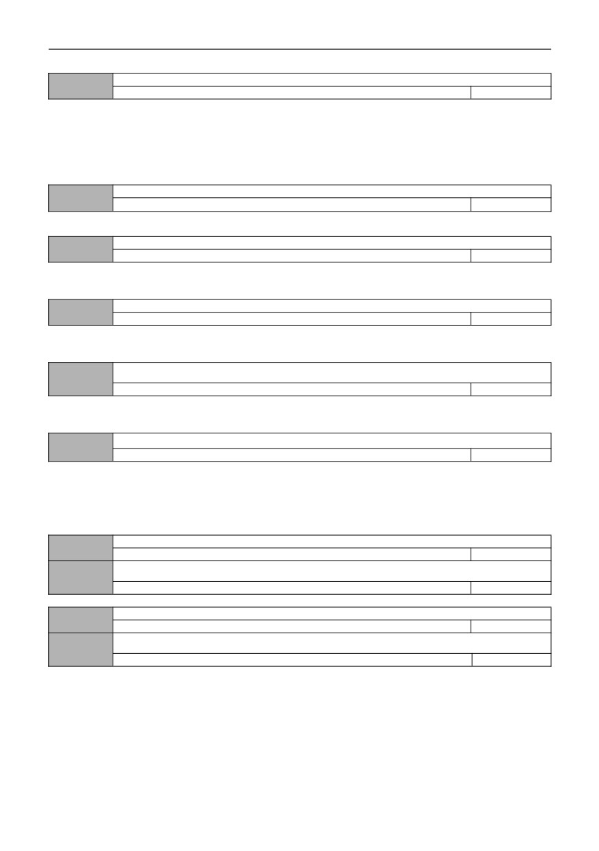
The above function codes are used to indicate the relevant information of the inverter, which can only be viewed and
cannot be modified.
Inverter type selection
14.18
0~1
0
0: G type (constant torque load type)
1: P type (fan, water pump load type)
In this inverter, the G/P model is combined, that is, the G model with a lower power can be used as a P model with a higher
power. But the premise is that this function code must be set to the corresponding value.
015 Group - Multi-pump water supply parameters
Terminal delay time
15.00
0.0~600.0s
0.1
The delay time when the pump is switched on and off.
Polling time
15.01
0.0~600.0h
48
Polling time is the time to switch the variable frequency pump regularly, which is only valid when a single pump is
operating.
Lower limit frequency of reducing the number of pump
15.02
0.0~600.00HZ
35.00
When the feedback pressure is higher than the set pressure and the frequency drops to the lower limit frequency of
pump reduction, the pump is reduced after the delay time of pump reduction.
Main pump start delay time
15.03
0.0~3600.0S
0.3
This parameter is used in "one drive three constant pressure water supply", after the main and auxiliary pumps are
switched, the main pump will start delay.
Auxiliary pump Start-up mode
15.04
0~1
0
0: Direct start
This method is mainly used for water pumps below 7.5KW. When the pressure is not enough, it can be started directly
at power frequency.
1: Soft start
This method is mainly used to start the two pumps at low frequency when one is driven by two.
Add pump delay time
15.05
0.0~3600.0S
10.0
Reduce pump delay time
15.06
0.0~3600.0S
10.0
Sensor range
15.07
0.000~60.000MPa
10.000
Pressure setting (MPa)
15.08
0.000~【08.25】
5.000
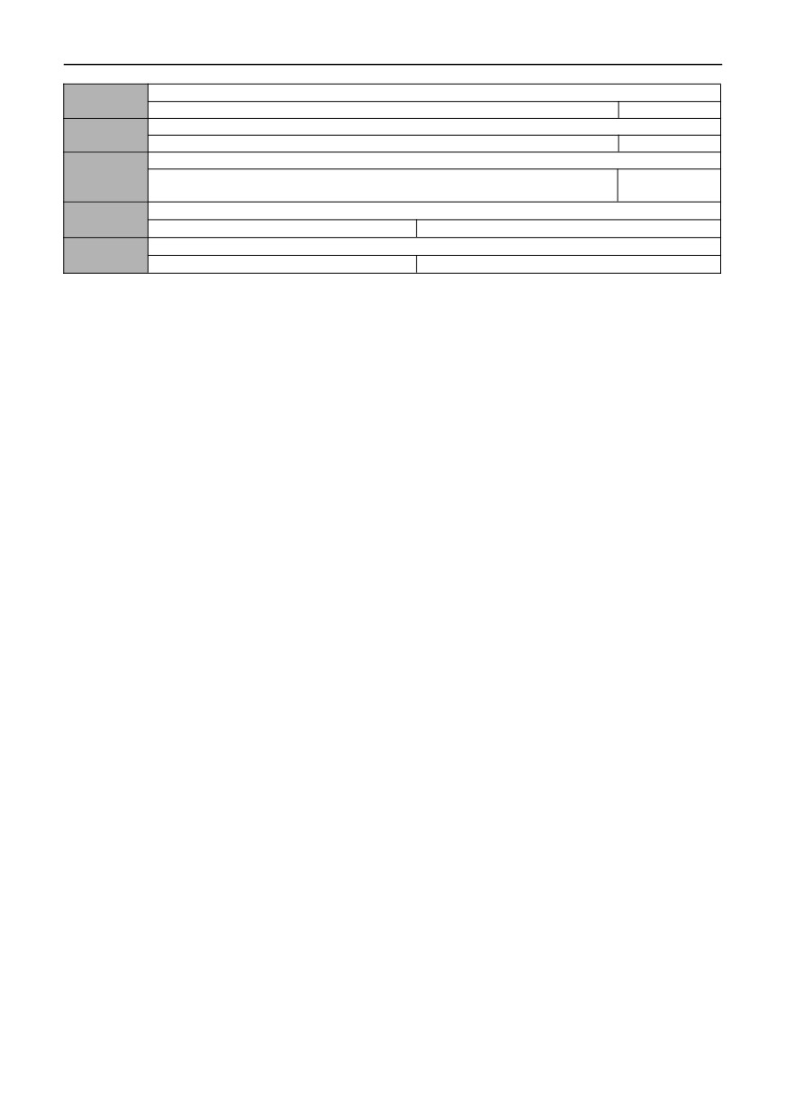
If P08.01=5, select the sensor range (15.07) and given pressure (15.08) according to the field conditions.
124
016 Group- Photovoltaic water pump parameters
Lack of water detect time
16.00
0~250s
10
MPPT low point operating voltage
16.01
0~MPPT High point operating voltage
350/200V
MPPT high point operating voltage
16.02
【16.01】~1000/
537/311V
【16.01】~500
Photovoltaic pump water shortage detection current corresponds to the ratio of no-load current
16.03
80.0~300.0%*No load current of motor
150.0
Minimum operating frequency of photovoltaic pump effluent
16.04
0.00Hz~ ~ upper limit frequency
20.00
If the bus voltage (d-12) is higher than the set value of MPPT high working voltage (16.02), run at the maximum
frequency; If it is lower than the set value of MPPT high-point working voltage (16.01), it will run at the frequency obtained
by (bus voltage /MPPT high-point working voltage) * maximum frequency; if the bus voltage reaches MPPT low-point
working voltage (16.01), it will run at the lowest running frequency (16.04); if the inverter runs above the lowest running
frequency, and the output current is less than the no-load current of motor
* water shortage detection current of
photovoltaic pump.
125
Chapter VIII EMC (Electromagnetic Compatibility)
8.1
Definitions
Electromagnetic compatibility (EMC) refers to the ability of electrical equipment to operate in an electromagnetic
interference environment without interfering with the electromagnetic environment and to stably realize its functions.
8.2
Introduction to EMC Standards
According to the requirements of national standard GB/T12668.3, the inverter needs to meet the requirements of
electromagnetic interference and anti-electromagnetic interference.
Our existing products comply with the latest international standard: I e c/e n 61800-3: 2004 (adjustable speed electrical
power drive systems part 3: EMC requirements and specific test methods), which is equivalent to the national standard
GB/T12668.3.
IEC/EN61800-3 mainly investigates inverters from two aspects: electromagnetic interference and anti-electromagnetic
interference. Electromagnetic interference mainly tests radiation interference, conduction interference and harmonic
interference of inverters (this requirement is applicable to inverters used for civil use). Anti-electromagnetic interference
mainly affects the transmission immunity, radiation immunity, surge immunity, fast burst immunity, ESD immunity and
power supply low-frequency end immunity (specific test items include:
1. Immunity test of input voltage sag, interruption and change;
2. Commutation notch immunity test;
3. Harmonic input immunity test;
4. Input frequency change test;
5. Input voltage imbalance test;
6. Input voltage fluctuation test). According to the strict requirements of IEC/EN61800-3, our products are installed and
used according to the instructions shown in 7.3, and will have good electromagnetic compatibility in general industrial
environment.
8.3
EMC guidance
8.3.1 Influence of harmonics:
High-order harmonics of power supply will damage the inverter. Therefore, it is suggested to install AC input reactors
in some places with poor power grid quality.
8.3.2 Electromagnetic interference and installation precautions:
There are two kinds of electromagnetic interference, one is the interference of the electromagnetic noise of the
surrounding environment to the inverter, and the other is the interference of the inverter to the surrounding equipment.
Precautions for installation:
1) the grounding wires of inverters and other electrical products shall be well grounded;
2) The power input and output lines and weak current signal lines (such as control lines) of the inverter should not be
arranged in parallel as far as possible, but should be arranged vertically when there are pieces;
3) It is recommended to use shielded cable or steel pipe to shield the power line for the output power line of the inverter,
and the shielding layer should be reliably grounded. For the lead of the interfered equipment, it is recommended to use
twisted shielded control line and reliably ground the shielding layer;
4) If the length of motor cable exceeds 100m, it is required to install output filter or reactor.
8.3.3 Treatment method of interference of peripheral electromagnetic equipment to
inverter:
Generally, the electromagnetic influence on the inverter is caused by a large number of relays, contactors or
electromagnetic brakes installed near the inverter. When the inverter malfunctions due to interference, the following
measures are recommended:
1) Surge suppressors are installed on devices that generate interference;
2) Install a filter at the input end of the inverter, refer to 7.3.6 for specific operation;
3) The leads of control signal lines and detection lines of inverters shall be shielded cables and the shielding layer shall
be grounded reliably.
8.3.4 Measures to deal with interference caused by inverter to peripheral
equipment:
There are two kinds of noise in this part: one is the radiation interference of inverter, and the other is the conduction
interference of inverter. These two kinds of interference make peripheral electrical equipment suffer electromagnetic or
126
electrostatic induction. Thereby causing misoperation of the equipment. According to several different interference
situations, refer to the following methods to solve them:
1) The instruments, receivers and sensors used for measurement have weak signals. If they are close to the inverter or
in the same control cabinet, they are prone to interference and misoperation. The following solutions are recommended: try
to stay away from interference sources; Do not arrange the signal line and the power line in parallel, especially do not
bundle them together in parallel; Shielding wires shall be used for signal lines and power lines, and the grounding shall be
good; Add ferrite magnetic ring on the output side of the inverter (choose the suppression frequency in the range of 30 ~
1000 MHz) and wind it for 2 ~ 3 turns in the same direction. For the bad situation, you can choose to install EMC output
filter;
2) When the interfered equipment and the inverter use the same power supply, it will cause conducted interference. If
the interference cannot be eliminated by the above methods, an EMC filter should be installed between the inverter and the
power supply (refer to 7.3.6 for selection operation);
3) The peripheral equipment is grounded separately, which can eliminate the interference caused by leakage current
in the grounding line of the inverter.
8.3.5 Leakage current and treatment:
There are two forms of leakage current when using inverter: one is leakage current to ground; The other is the leakage
current between lines.
1) factors affecting the floor drain current and solutions:
There is distributed capacitance between the conductor and the ground, and the greater the distributed capacitance,
the greater the leakage current; Effectively reduce the distance between inverter and motor to reduce distributed
capacitance. The larger the carrier frequency, the greater the leakage current. The carrier frequency can be lowered to
reduce leakage current. However, reducing the carrier frequency will lead to an increase in motor noise. Please note that
installing reactors is also an effective way to solve leakage current.
The leakage current will increase with the increase of loop current, so when the motor power is high, the corresponding
leakage current will be large.
2) Factors causing leakage current between lines and solutions:
There is distributed capacitance between the output wires of the inverter. If the current passing through the wires
contains higher harmonics, it may cause resonance and leakage current. At this time, if the thermal relay is used, it may
cause misoperation.
The solution is to reduce the carrier frequency or install an output reactor. When using the inverter, it is suggested that
no thermal relay should be installed between the inverter and the motor, and the electronic overcurrent protection function
of the inverter should be used.
8.3.6
Precautions for installing EMC input filter at power input end:
1)
Note: Please use the filter strictly according to the rated value; As the filter belongs of Class I electrical
appliances; the metal outer shell for the filter should have good contact with the metal for the installation cabinet of large
area; and it is required of have good conductivity continuity; otherwise; there will be the danger for electrical contact and
seriously affect the EMC effect.
2) Through EMC test, it is found that the filter ground must be connected to the same common ground as the PE end of
the inverter, otherwise the EMC effect will be seriously affected.
3) Install the filter as close as possible to the power input of the inverter.
127
Chapter IX Fault Diagnosis and Countermeasures
9.1
Fault Alarm and Countermeasures
In case of abnormality during operation, the inverter immediately blocks the PWM output and enters the fault protection
state. At the same time, the current fault information is indicated by the flashing fault code on the keyboard. At the same
time, the fault indicator ALM lights up. At this time, it is necessary to check the cause of the fault and the corresponding
treatment method according to the method suggested in this section. If the problem still cannot be solved, please contact
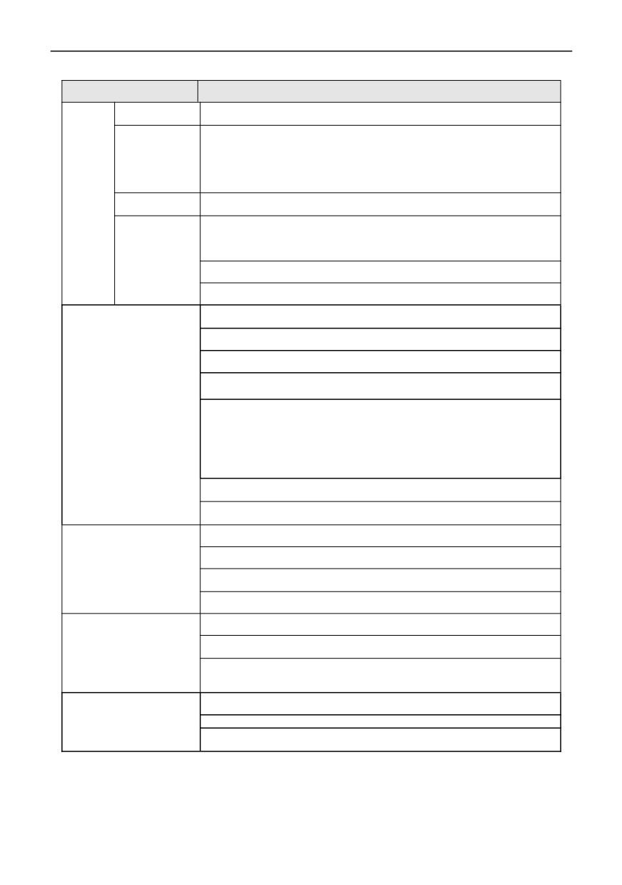
our company directly. Please refer to Table 9-1 Fault Diagnosis and Elimination for corresponding solutions.
Fault code
Name
Possible reason of fault
Fault countermeasures
Acceleration time is too short
Extended the acceleration time
(including tuning process)
Set to start after DC braking or
Restart the rotating motor
Overcurrent during
speed tracking start
E-01
acceleration
Choose a inverter with high
Low inverter power
power level
Improper setting of V/F curve or
Adjust V/F curve or torque lift
torque boost
Deceleration time is too short
Extended deceleration time
(including tuning process)
Overcurrent during
Choose a inverter with high
E-02
Low inverter power
deceleration
power level
External braking resistor or
Excessive load inertia
braking unit
Low grid voltage
Check the input power supply
Overcurrent in
Check the load or reduce the
E-03
The load is mutated or abnormal
constant speed
load mutation
Choose a inverter with high
Low inverter power
power level
Abnormal input voltage (including
Check the input power supply
tuning process)
Overvoltage during
Set to start after DC braking or
E-04
Restart the rotating motor
acceleration
speed tracking start
External braking resistor or
Special potential energy load
braking unit
Deceleration time is too short
Extended deceleration time
(including tuning process)
Overvoltage during
E-05
External braking resistor or
deceleration
Excessive load inertia
braking unit
Input voltage abnormal
Check the input power supply
Input voltage abnormal
Check the input power supply
Overvoltage in
E-06
External braking resistor or
constant speed
Special potential energy load
braking unit
Check the power supply
Input voltage is abnormal or
E-07
DC Bus undervoltage
voltage or ask the
contactor (relay) is not pulled in
manufacturer for service
Improper setting of V/F curve or
Adjust V/F curve or torque lift
torque boost
Grid voltage is too low
Check the grid voltage
E-08
Motor overload
The motor is locked or the load
Check the load
mutation is too large
Motor overload protection factor is
correctly set Motor overload
not set correctly
protection coefficient
Improper setting of V/F curve or
Adjust V/F curve or torque lift
torque boost
Grid voltage is too low
Check the grid voltage
E-09
Inverter overload
Acceleration time is too short
Extended the acceleration time
Choose a inverter with higher
The motor is overloaded
power
Output current is less than load drop
E-10
Inverter drop load
Check the load
detection value
Inverter output short circuit or
Check the motor wiring
grounding
Instantaneous overcurrent of
See overcurrent
inverter
countermeasures
E-11
Power module failure
Clear the air duct or replace the
Blocked air duct or damaged fan
fan
Abnormal control keypador serious
Seek services from
interference
manufacturers
128
Fault code
Name
Possible reason of fault
Fault countermeasures
Seek services from
Power device damage
manufacturers
Phase loss on the
Check the power supply and
E-12
Current Abnormality
input side
connection
Phase loss or current
E-13
imbalance on the
Output U, V and W are out of phase
Check the output wiring
output side
Output short circuit to
E-14
Reservation
Reservation
ground
Radiator
Ambient temperature is too high
Lower ambient temperatures
E-15
overheated1
Fan damaged
Replace the fan
E-16
Radiator
overheated2
Clogged air duct
Clear the air duct
Does not match the baud rate of the
Adjust baud rate
upper computer
Check whether the
communication connection is
RS485
shielded and the wiring is
E-17
RS485 channel interference
communication failure
reasonable. If necessary,
consider connecting the filter
capacitor in parallel
Communication timeout
Retry
The connection line between
Replace the connecting cable
Keyboard
E-18
keyboard and control board is
between keyboard and control
communication failure
damaged
board
Disconnect the fault input
External equipment
External equipment fault input
terminal of external equipment
E-19
fault
terminal closed
and clear the fault (pay
attention to check the cause)
Malfunction of hall element or
amplifier circuit
Current detection
Seek services from
E-20
Auxiliary power failure
error
manufacturers
Hall or power board wiring is in poor
contact
Incorrect setting of motor
Reset the motor parameters
parameters
The power specification of inverter
Seek services from
E-21
Motor tuning fault
and motor is serious
manufacturers
mismatch
Tuning timeout
Check the motor connection
EEPROM read-write
Seek services from
E-22
EEPROM fault
failure
manufacturers
Data error when inverter
Check the wire connection of
parameters are uploaded to keypad
the keypad
Data error when parameters are
Check the wire connection of
Error in copying
downloaded from the keypad to the
E-23
the keypad
parameters
inverter
Download parameters directly
Upload the parameters first,
without copying and uploading
then download them
parameters
Loose PID feedback circuit
Check the feedback connection
PID feedback
E-24
disconnection
The feedback amount is less than
Adjust the detection input
the disconnection detection value
threshold
Voltage feedback
The feedback amount is less than
Adjust the detection input
E-25
disconnection
the disconnection detection value
threshold
Running limit time
E-26
Run limit time reached
Seek services from agents
Arrival
EEPROM detection
Seek services from
E-27
EEPROM detection fault
fault
manufacturers
Water shortage
Water shortage detection fault of
See description of 16.00 ~
E-32
detection fault
photovoltaic pump
16.04 for details.
Bus undervoltage
See description of 05.25 ~
E-34
DC bus voltage is too low
automatic reset fault
05.26 for details.
129
9.2
Exception handling
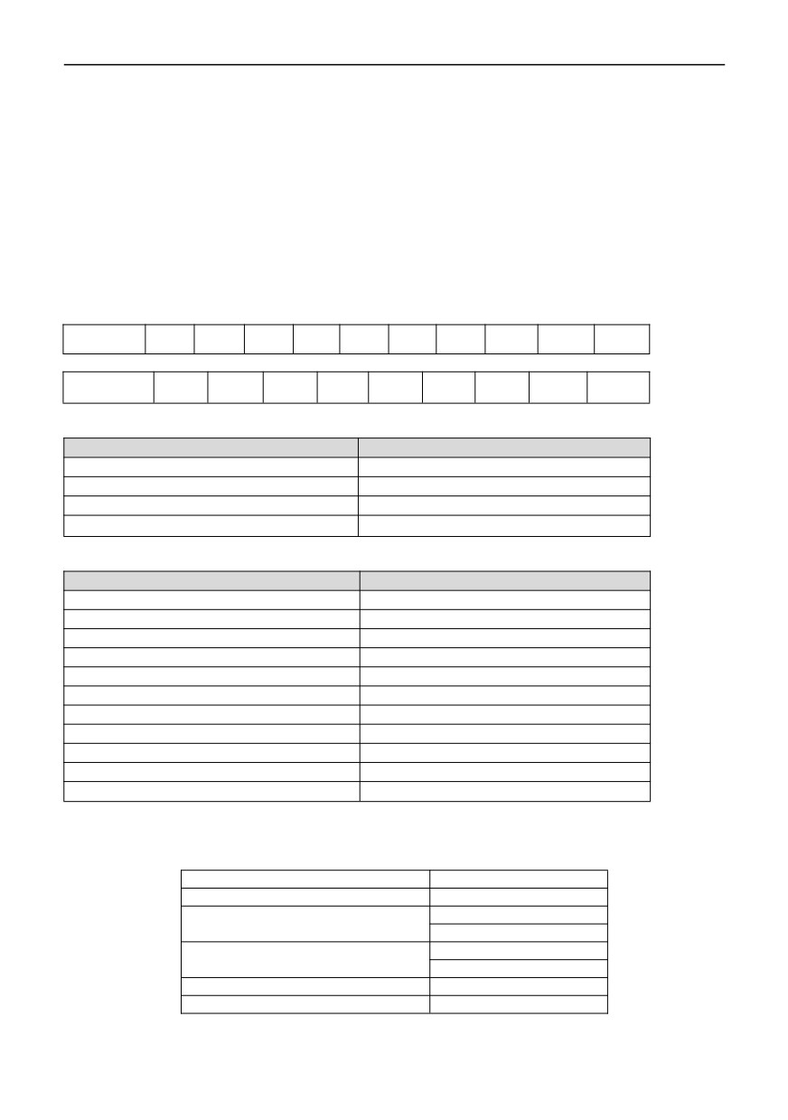
See table 9-2 for the common abnormal phenomena and countermeasures of inverter in operation:
Abnormal phenomena
Possible causes and countermeasures
Keyboard does
Check whether there is a power outage, whether the input power supply is out of
not display
phase, and whether the input power cord is connected incorrectly
Check whether there are problems with the wiring and sockets related to the
The keyboard is
keyboard, and measure the voltage of each control power supply in order to
not displayed,
confirm whether the switching power supply works normally. If the switching
but the internal
power supply does not work normally, check whether the inlet (+,-) sockets of the
charging
switching power supply are connected well, whether the starting vibration is
The
indicator is on
damaged or whether the voltage stabilizing tube is normal.
motor
The motor is
does
The motor load is too heavy, try to reduce the load
buzzing
not
rotate
Check whether it is in tripping state or not reset after tripping, whether it is in
power-off restart state, whether the keyboard has been reset, whether it has
entered program running state, multi-speed running state, specific running state
No
or non-running state, and try to restore the factory value.
abnormalities
were found
Confirm whether the operation instruction is given
Check whether the operating frequency is set to 0
Inappropriate setting of acceleration and deceleration time, increase acceleration
and deceleration time
If the current limiting value is set too small, increase the limiting value
Over-voltage protection acts during deceleration to increase deceleration time
Improper setting of carrier frequency, overload or oscillation
Overload and insufficient torque. Increase the torque boost value in V/F mode. If
The motor cannot accelerate
and decelerate smoothly
it still cant meet the requirements, you can switch to automatic torque boost
mode. At this time, pay attention to the fact that the motor parameters should be
consistent with the actual values. If it still cant meet the requirements, it is
recommended to switch to advanced V/F control mode. At this time, you should
still pay attention to whether the motor parameters are consistent with the actual
values, and it is best to tune the motor parameters.
The motor power does not match the inverter power. Please set the motor
parameters to actual values
One with more than one motor. Please change the torque lifting mode to manual
lifting mode
Inappropriate setting of upper and lower frequency limits
Although the motor can
The frequency setting is too low, or the frequency gain setting is too small
rotate, it can not adjust the
Check whether the speed regulation mode used is consistent with the set
speed
frequency
Check whether the load is too heavy, over-voltage stall or over-current limit
Load fluctuates frequently, so minimize its variation
Inverter is seriously inconsistent with motor rating. Please set the motor
The speed of the motor
parameters to actual values
changes during operation
Poor contact of frequency setting potentiometer or fluctuation of frequency given
signal. Change to digital frequency giving mode or increase the filtering time
constant of analog input signal
Adjust the phase sequence of output terminals u, v and W.
The rotation direction of the
Set the running direction (00.18=1) to reverse
motor is opposite
Direction uncertainty caused by output phase failure, please check the motor
wiring immediately
130
Appendix 1: Modbus communication protocol
1. RTU mode and format
When the controller communicates on Modbus bus in RTU mode, every 8-bit byte in the information is divided into 2
4-bit hexadecimal characters, which
The main advantage of mode is that the density of characters transmitted by mode is higher than that of ASCII mode at
the same baud rate, and every message must be continuously transmitted.
(1) the format of each byte in 1)RTU mode
Coding system: 8-bit binary, hexadecimal 0-9, A-F.
Data bit:
1-bit start bit, 8-bit data (lower bit first sent), 1-bit stop bit, and optional parity bit. (Refer to RTU data
frame as sequence diagram)
Error check area: cyclic redundancy check (CRC).
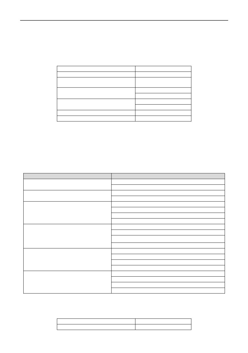
(2)RTU data frame bit sequence diagram
With parity check
Start
1
2
3
4
5
6
7
8
Far
Stop
No parity check
Start
1
2
3
4
5
6
7
8
Stop
2. Registers address and function code of series inverter
(1) Supported function codes
Function code
Functional Description
03
Read multiple registers
06
Write a single register
10
Write multiple registers continuously
13
Read a single parameter
(2) Register address
(2)Register Map
Address
Control command input
0DI2000
Monitoring parameter reading
0xD000(0DI1D00)~0xD039(0DI1D39)
MODBUS frequency setting
0DI201
MODBUS torque setting
0DI2002
MODBUS PID frequency given
0DI2003
MODBUS PID feedback setting
0DI2004
MODBUS analog output AO1 control
0di2005 (0 ~ 7fff means 0% ~ 100%)
MODBUS analog output AO1 control
0DI2006(0~7FFF means 0%~100%)
MODBUS pulse DO output control
0DI2007(0~7FFF means 0%~100%)
MODBUS digital output terminal control
0DI2008
Parameter setting
0x0000~0xF016
(3) Read multiple parameters in 3)03H (read 8 items continuously at most)
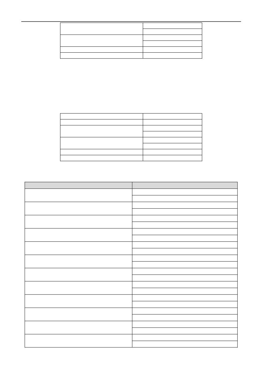
Inquiry information frame format:
Address
01H
Function
03H
00H
Starting data address
01H
00H
Number of Data(Byte)
02H
CRC CHK High
95H
CRC CHK Low
CBH
131
Analysis of this data:
01H is the inverter address
03H is the read function code
001H is item 00.01 of the starting address similar to the control keypad.
0002H is the number of items in the reading menu, and two items are 00.01 and 00.02
95CBH is a 16-bit CRC check code
The Response information frame format (return frame)
Address
01H
Function
03H
DataNum*2
04H
00H
Data1[2Byte]
00H
00H
Data2[2Byte]
01H
CRC CHK High
3BH
CRC CHK Low
F3H
Analysis of this data:
01H is the inverter address
03H is the read function code
04H is the product of reading item *2
0000H reads the data of item 00.01
001H reads the data of item 00.02
3BF3H is a 16-bit CRC check code
Example:
Name
Frame lattice
Send frame: 01H 03H 001H 0002H 95CBH
Read the data of 00.01 and 00.02
Return frame: 01H03H04H00000H01H3BF3H
Send frame: 01H 03H 0201H 001H D472H
Read the data of item 02.01
Return frame: 01H 03H 02H 000FH F840H
Send frame: 01H 03H D000H 001H BCCAH
Read the monitoring parameters of item d-00
Return frame: 01H 03H 02H 1388H B512H
(the address D000H and 1D00H are common)
Send frame: 01H 03H 1D00H 001H 8266H
Return frame: 01H 03H 02H 1388H B512H
Send frame: 01H 03H A000H 001H A60AH
Read the status of inverter during shutdown (the
Return frame: 01H 03H 02H 0040H B9B4H
address A000H is common with 1A00H, refer to
Send frame: 01H 03H 1A00H 001H 8312H
the description of inverter running status later)
Return frame: 01H 03H 02H 0040H B9B4H
Send frame: 01H 03H E000H 001H B3CAH
Read the fault code E-19 (the address E000H
Return frame: 01H 03H 02H 013H F989H
and 1E00H are common, refer to the following
Send frame: 01H 03H 1E00H 001H 8222H
inverter fault code table)
Return frame: 01H 03H 02H 013H F989H
Send frame: 01H 03H E01H 001H E20AH
Read the warning code A-18 (the address E01H
Return frame: 01H 03H 02H 012H 3849H
is common with 1E01, refer to the warning code
Send frame: 01H 03H 1E01H 001H D3E2H
table of the inverter behind)
Return frame: 01H 03H 02H 012H 3849H
(4) Write a single parameter in 4)06H
Inquiry information frame format:
Address
01H
Function
06H
132
20H
Starting data address
00H
00H
Data(2Byte)
01H
CRC CHK Low
43H
CRC CHK High
CAH
Analysis of this data:
01H is the inverter address
06H is the write function code
2000H is the control command address
001H is the forward command
43CAH is a 16-bit CRC validation code
The Response information frame format (return frame)
Address
01H
Function
06H
20H
Starting data address
00H
00H
Number of Data(Byte)
01H
CRC CHK High
43H
CRC CHK Low
CAH
Analysis of this data:
If the settings are correct, return the same input data
Example:
Name
Frame lattice
Send frame: 01H 06H 2000H 001H 43CAH
Forward
Return frame: 01H 06H 2000H 001H 43CAH
Send frame: 01H 06H 2000H 0009H 420CH
Reverse rotation
Return frame: 01H 06H 2000H 0009H 420CH
Send frame: 01H 06H 2000H 0003H C20BH
Shutdown
Return frame: 01H 06H 2000H 0003H C20BH
Send frame: 01H 06H 2000H 0004H 83C9H
free stop
Return frame: 01H 06H 2000H 0004H 83C9H
Send frame: 01H 06H 2000H 010H 43CAH
Reset
Return frame: 01H 06H 2000H 010H 43CAH
Send frame: 01H 06H 2000H 0002H 03CBH
Forward JOG
Return frame: 01H 06H 2000H 0002H 03CBH
Send frame: 01H 06H 2000H 000AH 020DH
Reverse JOG
Return frame: 01H 06H 2000H 000AH 020DH
Send frame: 01H 06H 0800H 001H 4A6AH
Set the parameter of item 08.00 to 1
Return frame: 01H 06H 0800H 001H 4A6AH
Send frame: 01H 06H 201H 0FA0H D642H
MODBUS the given frequency is 40HZ
Return frame: 01H 06H 201H 0FA0H D642H
Send frame: 01H 06H 2003H 01F4H 721DH
The MODBUS PID given value is 5V
Return frame: 01H 06H 2003H 01F4H 721DH
Send frame: 01H 06H 2004H 0190H C237H
The feedback value of MODBUS PID is 4V
Return frame: 01H 06H 2004H 0190H C237H
Send frame: 01H 06H 2002H 0320H 22E2H
MODBUS the torque is set as 80:
Return frame: 01H 06H 2002H 0320H 22E2H
133
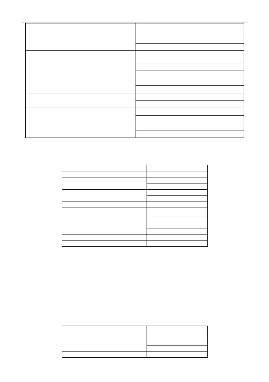
Send frame: 01H 06H AD00H 001H 68A6H
Validate user password (address AD00H and 1C00H
Return frame: 01H 06H AD00H 001H 68A6H
are common)
Send frame: 01H 06H 1C00H 001H 4F9AH
Return frame: 01H 06H 1C00H 001H 4F9AH
Send frame: 01H 06H AD01H 0002H 7967H
Verification operation restriction function password
Return frame: 01H 06H AD01H 0002H 7967H
(address AD01H and 1C01H are common)
Send frame: 01H 06H 1C01H 0002H 5E5BH
Return frame: 01H 06H 1C01H 0002H 5E5BH
Send frame: 01H 06H 2005H 3FFFH C3BBH
MODBUS analog output AO1 controls output 5V
Return frame: 01H 06H 2005H 3FFFH C3BBH
Send frame: 01H 06H 2006H 7FFFH 027BH
MODBUS analog output AO1 controls output 10V
Return frame: 01H 06H 2006H 7FFFH 027BH
Send frame: 01H 06H 2007H 3FFFH 627BH
MODBUS pulse DO output control output 25KHz
Return frame: 01H 06H 2007H 3FFFH 627BH
Send frame: 01H 06H 2008H 001H C208H
MODBUS digital output terminal Y1 controls the output
Return frame: 01H 06H 2008H 001H C208H
(5) Write multiple parameters continuously
Inquiry information frame format:
Address
01H
Function
10H
01H
Starting data address
00H
00H
Number of Data(Byte)
02H
DataNum*2
04H
00H
Data1(2Byte)
01H
00H
Data2(2Byte)
02H
CRC CHK High
2EH
CRC CHK Low
3EH
Analysis of this data:
01H is the inverter address
10H is the write function code
0100H is item 01.00 of the starting address similar to the control keypad.
0002H is the number of registers
04H is the total number of bytes (number of 2* registers)
001H is the data of 01.00 items
0002H is the data of 01.01 items
2E3EH is a 16-bit CRC validation code
The Response information frame format (return frame)
Address
01H
Function
10H
01H
Starting data address
00H
Number of Data(Byte)
00H
134
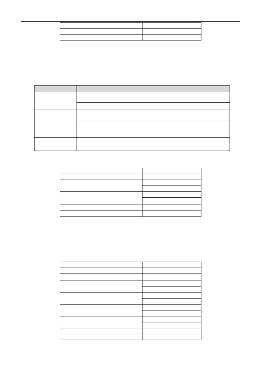
02H
CRC CHK High
40H
CRC CHK Low
34H
Analysis of this data:
01H is the inverter address
10H is the write function code
0100H is the data of write 01.00 items
0002H is the number of items written in the menu, and 01.00 and 01.01
4034H is a 16-bit CRC check code
Example:
Name
Frame lattice
Set the parameters
Send frame: 01H
10H
0100H
0002H
04H
001H
0002H
2E3EH
of 01.00 and 01.01
to 1 and 0.02.
Return frame: 01H 10H 0100H 0002H 4034H
The
given
Send frame:01H
10H
2000H
0002H
04H
001H
1388H
36F8H
frequency
of
forward
rotation
and communication
Return frame: 01H 10H 2000H 0002H 4A08H
is 50Hz
Set the parameter
Send frame:01H
10H
0100H
001H
02H
001H
7750H
of item 01.00 to 1
Return frame: 01H 10H 0100H 001H 0035H
(6) Read a single parameter (including attribute, minimum value and maximum value) in 6)13H
Inquiry information frame format:
Address
01H
Function
13H
00H
Starting data address
0CH
00H
Number of Data(Byte)
04H
CRC CHK High
45H
CRC CHK Low
CBH
Analysis of this data:
01H is the inverter address
13H is the read function code
000CH is item 00.12 of the starting address similar to the control keypad.
0004H is the number of registers
45CBH is a 16-bit CRC validation code
Inquiry information frame format(return frame):
Address
01H
Function
13H
Starting data address
08H
13H
Data1(2Byte)
88H
03H
Data2(2Byte)
22H
00H
Data3(2Byte)
00H
13H
Data4(2Byte)
88H
CRC CHK High
28H
CRC CHK Low
31H
Analysis of this data:
135
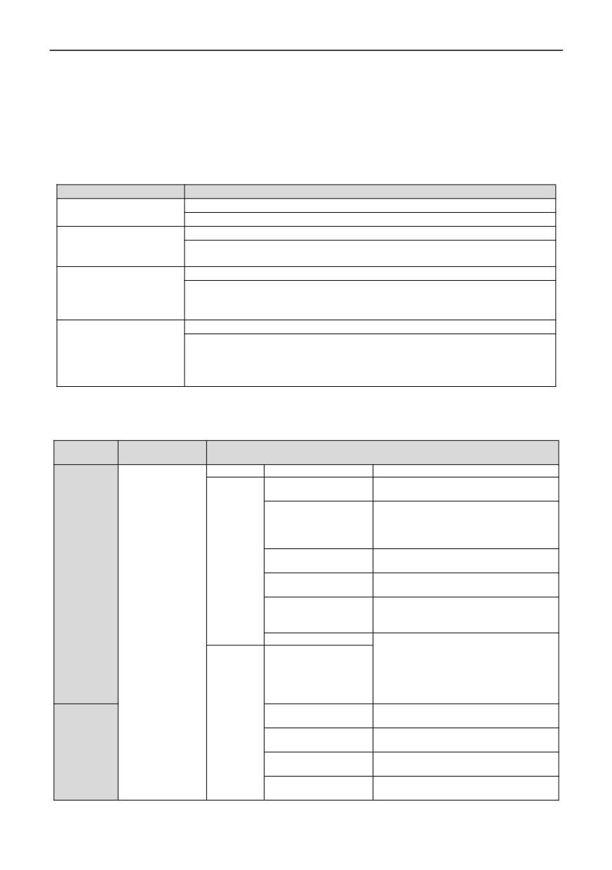
01H is the inverter address
13H is the write function code
08H is the total number of bytes (number of 2* registers)
1388H is the parameter value
0322H is the attribute value
0000H is the minimum value
1388H is the maximum value
2831H is a 16-bit CRC check code
Example:
Name
Frame lattice
Read the parameter value
Send frame: 01H 13H 000CH 001H 85CAH
of item 00.12
Return frame: 01H 13H 02H 1388H B1D2H
Read the parameter value
Send frame: 01H 13H 000CH 0002H C5CBH
of item
00.12
+ the
Return frame:01H
13H
04H
1388H
0322H
FC00H
attribute value
Read the parameter
Send frame: 01H 13H 000CH 0003H 040BH
value+attribute
value+minimum value of
Return frame:01H
13H
06H
1388H
0322H
0000H
628BH
item 00.13
Read the parameter
Send frame: 01H 13H 000CH 0004H 45CBH
value+attribute
value+minimum
Return frame:01H
13H
08H
1388H
0322H
0000H
1388H
2831H
value+maximum value of
item 00.13
3. Description of other register address functions:
Functional
address
Explanation of data meaning
Description
definition
bytes
bit
Meaning
0: no-operation
Bit7
1: Overload warning
0:INV_220V
1:INV_380V
Bit6~Bit5
2:INV_660V
3:INV_1140V
0: no-operation
Byte1
Bit4
1: power-down storage
Inverter
0:no-operation
running
Bit3
1:Reset
state
0: no-operation
Bit2~Bit1
1. Static tuning
2. Dynamic tuning
A000H(1A00H)
Bit0
0: the keypad runs
the command
channel
1: terminal operation command channel
Bit7
2: Communication operation command
channel
3: Reservation
0: no-operation
Bit6
Byte0
1: the bus voltage is normal
0: no-operation
Inverter
Bit5
1. Undervoltage
running
0: no-operation
state
Bit4
1: JOG
0: forward
Bit3
1: reverse
136
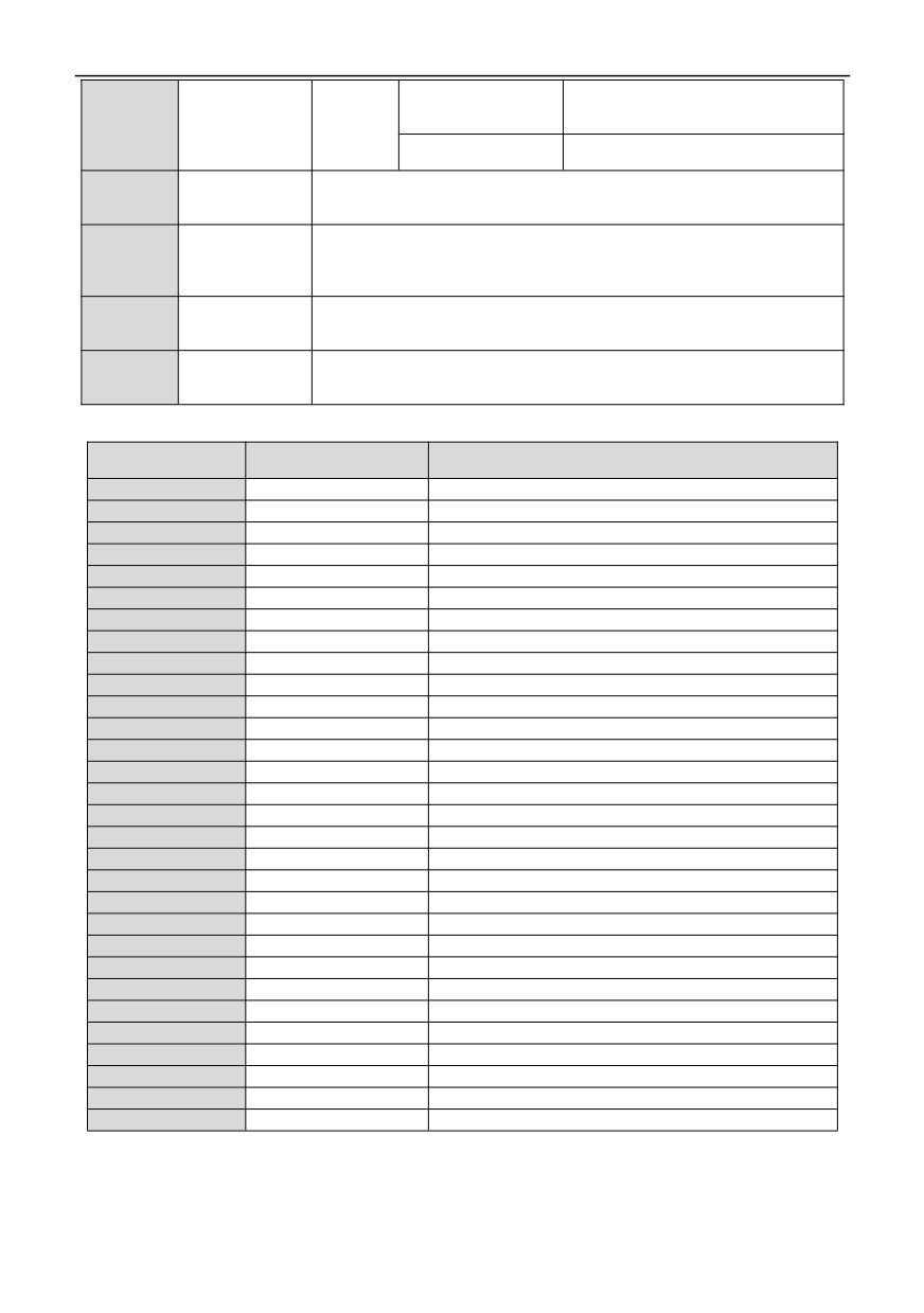
1: Accelerate operation
Bit2~Bit1
2. Decelerating operation
3. Running at a constant speed
0: shutdown status
Bit0
1: Running status
Read the
Address E000H and 1E00H are common (see fault code table and example of
inverter
E000H(1E00H)
reading function code 03H).
fault code
Read the
inverter
Address E01H and 1E01H are common (see the list of warning codes and the
E01H(1E01H)
fault alarm
example of reading function code 03H)
code
User
Addresses AD00H and 1C00H are common (see the example of writing function
password
AD00H(1C00H)
code 06H)
validation
Run limit
Addresses AD00H and 1C00H are common (see the example of writing function
password
AD01H(1C01H)
code 06H)
validation
4. inverter fault code table:
Keyboard display
Fault code
Fault information
content
0000H
——
No Fault
001H
E-01
Accelerating running in operation
0002H
E-02
Overcurrent in deceleration operation
0003H
E-03
Overcurrent in constant speed operation
0004H
E-04
Overvoltage during acceleration in the operation
0005H
E-05
Overvoltage during deceleration in the operation
0006H
E-06
Overvoltage during Constant speed in the operation
0007H
E-07
DC Bus undervoltage
0008H
E-08
Motor overload
0009H
E-09
Inverter overload
000AH
E-10
Inverter off is loaded
000BH
E-11
Power module failure
000CH
E-12
Input side open phase
000DH
E-13
Output side is out of phase or unbalanced in current
000EH
E-14
Output short circuit fault to ground
000FH
E-15
Overheating radiator 1
010H
E-16
Overheating radiator 2
011H
E-17
RS485 communication failure
012H
E-18
Keyboard communication failure
013H
E-19
External equipment fault
014H
E-20
Current detection error
015H
E-21
Motor tuning fault
016H
E-22
EEPROM read-write failure
017H
E-23
Error in copying parameters
018H
E-24
PID feedback disconnection
019H
E-25
Voltage feedback disconnection
01AH
E-26
Run limit time reached
01BH
E-27
EEPROM detection fault
0020H
E-32
Water shortage detection fault
0022H
E-34
Bus undervoltage automatic reset fault
137
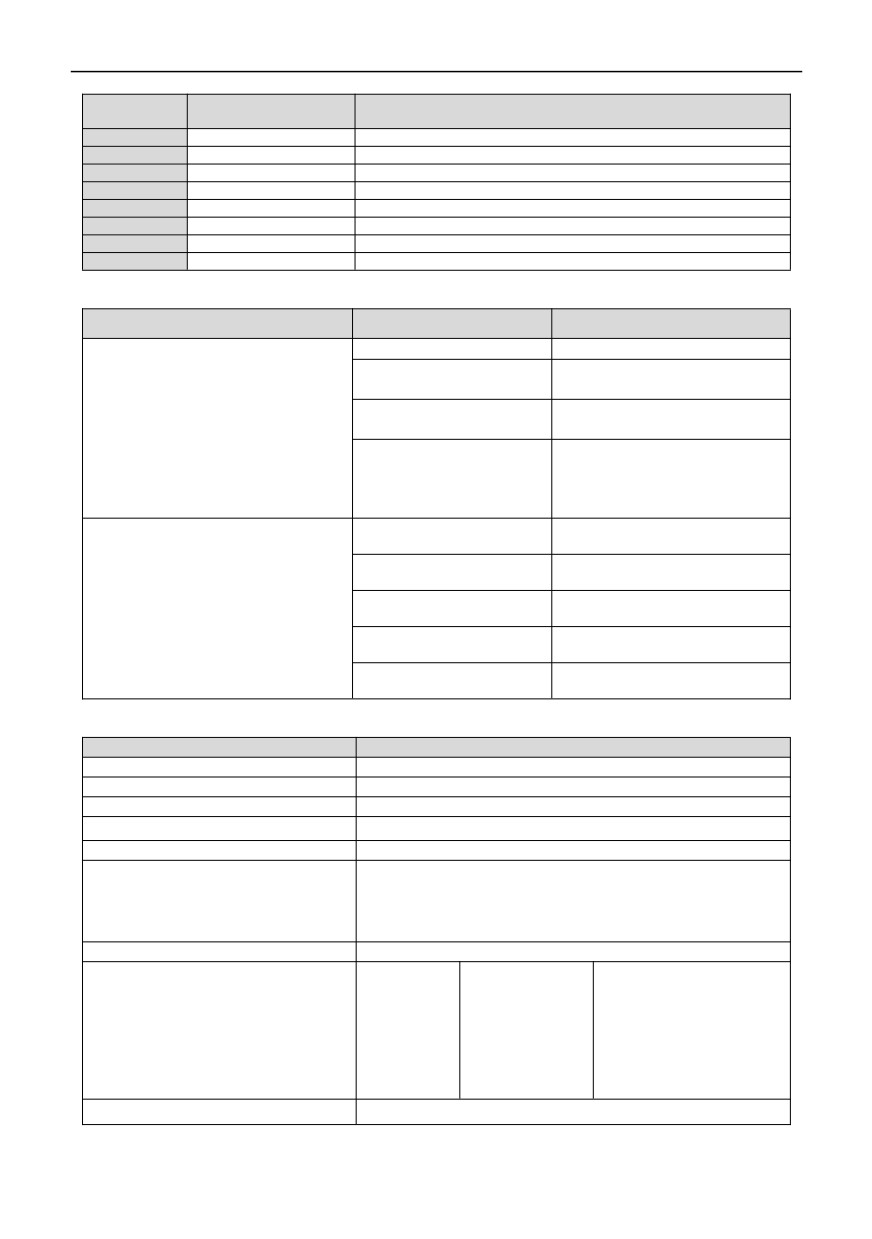
5. inverter warning code table:
Keyboard display
Alarm code
Fault information
content
0000H
——
No Fault
0005H
A-05
Torque arrival alarm
0009H
A-09
Inverter overload alarm
011H
A-17
RS485 communication failure alarm
012H
A-18
Keyboard communication failure alarm
015H
A-21
Motor tuning fault alarm
016H
A-22
EEPROM read-write failure alarm
018H
A-24
PID feedback disconnection alarm
6. Control command word format (see the example of writing function code 06H):
Address
bit
Meaning
Bit7~Bit5
Reservation
0: no-operation
Bit4
1: Reset
0: forward
Bit3
2000H
1: reverse
100: free stop
011: shutdown
Bit2~Bit0
01: JOG Operation
01: Operation
Bit7~Bit4
Reservation
Bit3
Output of programmable relay R1
2008H (press position 1 as output, press
Bit2
Output of programmable relay R1
position 0 as close)
Bit1
Open collector output terminal Y2
Bit0
Open collector output terminal Y1
7. Parameter attribute table:
bit
Meaning
Bit15
Reservation
Bit14
Menu
Bit13
system
Bit12
Restore factory value coverage
Bit11
EEPROM
"○":01
"×":10
Bit10~Bit9
"◆":11
"◇":00
Bit8
Symbol
1:00000
KHZ:01100
us:1001
V:0001
KW:01010
HZ/S:10000
A:0010
om:01110
mh:1010
Bit7~Bit3
rpm:0011
ms:0101
C:1011
HZ:0100
MA:01011
m/s:10100
%:0110
KM:01101
H:10101
S:01000
CM:01111
KWH:10110
Bit2~Bit0
Decimal point
138
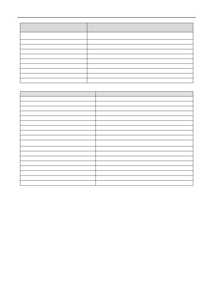
8. Error code meaning of slave response abnormal information:
Error Code
Description
01H
Illegal function code
02H
Illegal address
03H
Illegal data
04H
Illegal register length
05H
Error in CRC check
06H
Parameters cannot be modified during operation
07H
Parameters cannot be modified
08H
Invalid upper PC control command
09H
Parameters are password protected
0AH
Password error
9. Correspondence addresses corresponding to all parameters of series inverters:
Function code
Communication address
00.00~00.20
6000H~6014H
01.00~01.36
6100H~6124H
02.00~02.17
6200H~6211H
03.00~03.08
6300H~6308H
04.00~04.27
6400H~641BH
05.00~05.24
6500H~6518H
06.00~06.52
6600H~6634H
07.00~07.40
6700H~6728H
08.00~08.24
6800H~6818H
09.00~09.73
6900H~6949H
10.00~10.35
6A00H~6A23H
11.00~11.08
6B00H~6B08H
12.00~12.30
6C00H~6C1EH
14.00~14.18
6E00H~6E12H
15.00~15.08
6000H~6008H
16.00~16.04
7000H~7004H
FFF.00~FFF.22
7100H~7116H
d-00~d-57
D000H(1D00H)~D039H(1D39H)
Notes:
1. In the above examples, the address of the inverter is selected as 01 for convenience of explanation. When the inverter is
a slave, the address is set in the range of 1 ~ 247. If any data in the frame format is changed, the check code should be
recalculated. You can download the CRC16-bit check code calculation tool online.
2. The starting address of the monitored items is D000, and each item is offset by the corresponding hexadecimal value
based on this address, and then added to the starting address. For example, the monitoring start item is D-00, and the
corresponding start address is D000H (1D00H). Now read the monitoring item D-18, 18-00 = 18, and if 18 is converted into
hexadecimal for 12H, then the reading address of D-18 is D000h+12h = D012h (1D01H
3. The frame format when the slave response information is abnormal: inverter address+(80H+ function code)+error
code+16-bit CRC check code; If the frame returned by the slave is 01H+83H+04H+40F3H;; 01H is the slave address, 83H
is 80H+03H, indicating read error, 04H indicates illegal data length, and 40F3H is a 16-bit CRC check code.
139