HV100 Series Frequency Inverter. User Manual (V4.0) - page 6
0: deceleration and shutdown
1: free stop
Deviation between feedback and set pressure when entering sleep
08.14
0.0~10.0%
0.5%
This function parameter is only valid for the second sleep mode.
Sleep threshold
08.15
0.00~200.0%
100.0%
This threshold is the percentage of the given pressure, and this function parameter is only valid for the first sleep mode
relative to the setting.
Awakening threshold
08.16
0.00~200.0%
90.0%
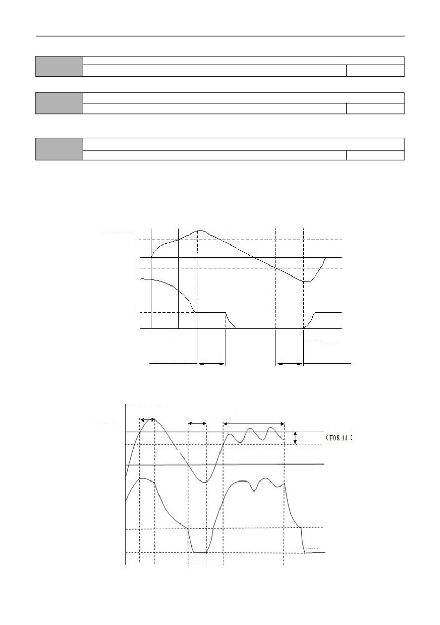
08.15 defines the feedback limit when the inverter enters the sleep state from the working state. If the actual feedback
value is greater than the set value, and the frequency output by the inverter reaches the lower limit frequency, the inverter
will go to sleep after the delay waiting time defined in 08.17 (i.e. running at zero speed).
08.16 defines the feedback limit of inverter from sleeping state to working state. When PID polarity selects positive
characteristic, if the actual feedback value is less than the set value (or when PID polarity selects negative characteristic, if
the actual feedback value is greater than the set value), the inverter will get out of sleep and start working after the delay
waiting time defined in 08.18.
PID feedback
Sleep min value
PID settings
Wake up min value
Output frequency
Lower rate frequency
Zero frequency
Sleep
Wake-up
Sleep detection
Wake-up
time
detection time
Figure F8-5 Schematic diagram of the first sleep mode
PID sleep delay
PID wake-up delay
PID sleep delay
PID set value
Setting
Deviation
PID
feedback
Wake up min value
Output frequency
Lower rate frequency
Sleep
Zero frequency
Sleep Wake-
up
Figure F8-6 Schematic diagram of the second sleep mode
100
Sleep delay time
08.17
0.0~600.0S
100.0
Wake delay time
08.18
0.0~600.0S
5.0
Proportional gain KP2
08.19
0.01~100.00s
5.00
Integration time Ti2
08.20
0.01~10.00s
0.05
Differential time Td2
08.21
0.01~10.00s
0.00
Upper limit cut-off frequency of PID
08.22
【08.23】~300.00Hz
50.00
Lower limit cut-off frequency of PID
08.23
-300.00Hz~【08.22】
0.00
Sleep frequency
08.24
0.00Hz~【00.13】
0.00
009 group-simple PLC, multi-speed
Selection of PLC operation mode
09.00
0~3
0
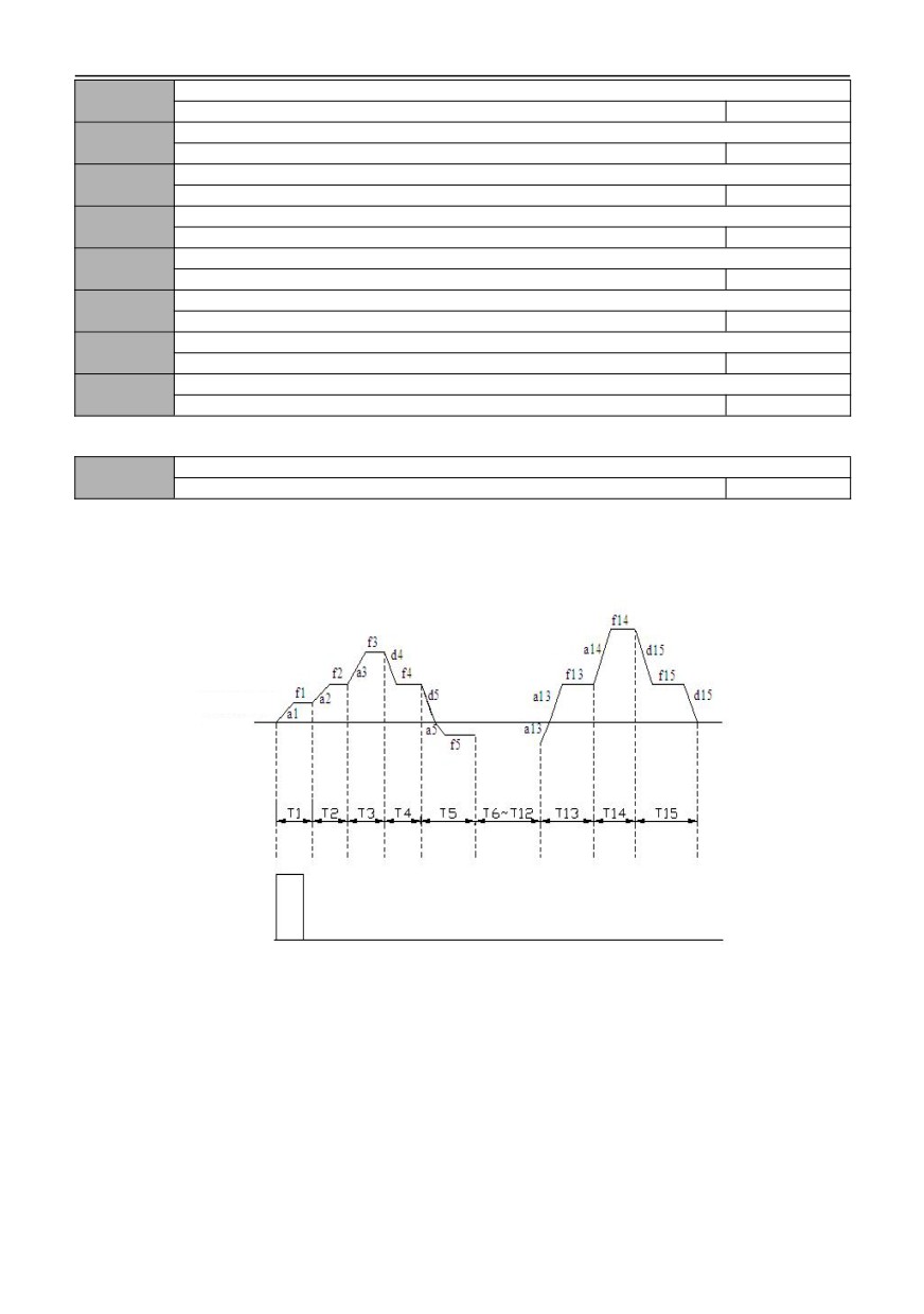
0: Stop after single cycle
The inverter stops automatically after completing a single cycle, and it needs to give the running command again
before starting. If the running time of a certain stage is 0, the running time skips the stage and goes directly to the next
stage. As shown in the figure below:
PLC command
RUN command
Fig. F9-1 Schematic diagram of PLC shutdown after single cycle
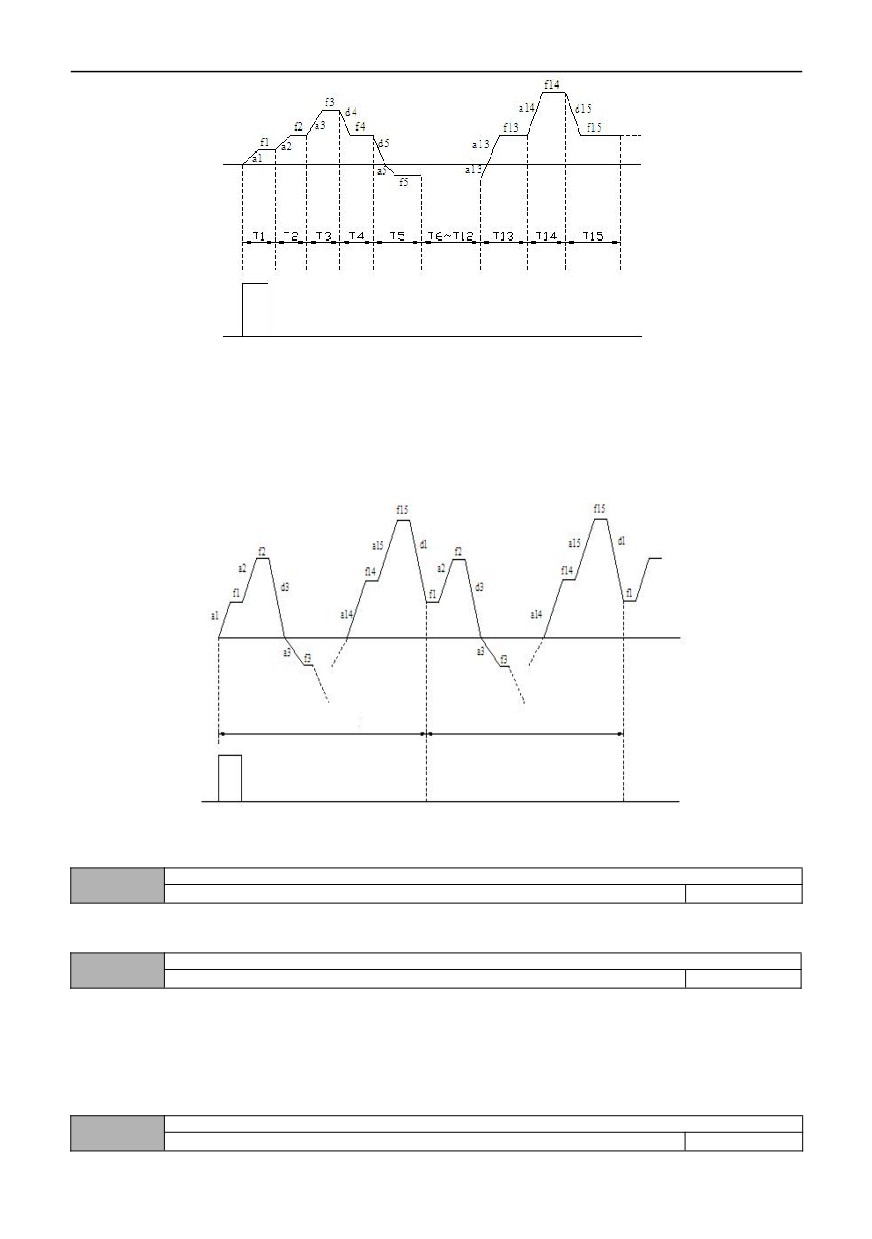
1: Keep the final value running after a single cycle
After completing a single cycle, the inverter automatically keeps the running frequency and direction of the last section to
keep running. As shown in the figure below:
101
PLC command
RUN command
Fig. F9-2 Schematic diagram of PLC maintenance after single cycle
2: Finite continuous cycle
The inverter determines the cycle times of PLC operation according to the limited number of continuous cycles set in
09.04, and stops when the cycle times are reached. 09.04=0, the inverter is not running.
3: Continuous circulation
After completing one cycle, the inverter will automatically start the next cycle, and will not stop until there is a stop
command. As shown in the figure below:
First cycle
Second cycle
RUN command
Figure F9-3 Schematic diagram of PLC continuous cycle
Operation mode of PLC
09.01
0~1
0
0: Automatic
1: Manually operation through the defined multi-function terminal
Memory of PLC running power failure
09.02
0~1
0
0: Not store
Do not remember the PLC running state when power is cut off, and restart after power-on to start running from the first
section.
1: Remember the stage and frequency of power-down time
Memorize PLC running state when power is cut off, including power-off time stage, running frequency and running time.
Start again after power-on, automatically enter this stage, and continue to run for the rest of the time at the frequency
defined by this stage.
PLC starting mode
09.03
0~2
0
102
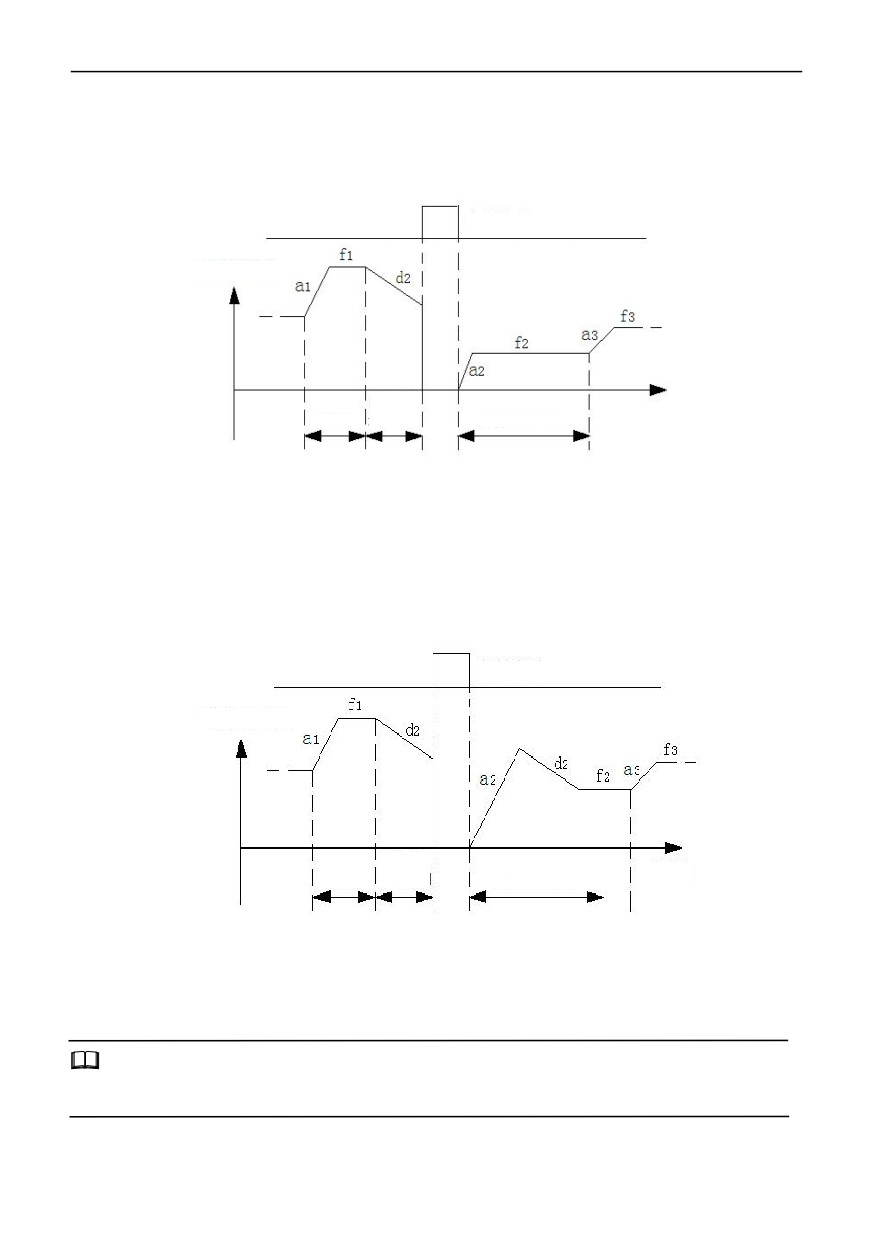
0: Restart from the first stage
Stop during operation (caused by shutdown command, fault or power failure), and start operation from the first section
after restart.
1: Start from the stage of shutdown (failure) time
In case of shutdown during operation (caused by shutdown command, fault or power failure), the inverter automatically
records the running time of the current stage, and automatically enters this stage after restarting, and continues to run for
the remaining time at the frequency defined by this stage, as shown in the following figure:
Interrupt signal
Output frequency
Stage 2
elapsed
Time
Stage
1
time
Stage 2 remaining time
a1: Stage 1 Acceleration Time
f1: Stage 1 Frequency
a2: Stage 2 Acceleration Time
f2: Stage 2 Frequency
a3: Stage 3 Acceleration Time
f3: Stage 3 Frequency
d2: Stage 3 deceleration time
Fig. F9-4 PLC starting mode 1
2: Start from the stage and frequency of shutdown (failure) time
In case of shutdown during operation (caused by shutdown command, fault or power failure), the inverter not only
automatically records the running time at the current stage but also records the running frequency at the shutdown time,
and then recovers to the running frequency at the shutdown time after starting again, and the remaining phases of the
frequency run, as shown in the following figure:
Interrupt signal
Output frequency
Stage 2
elapsed
Time
Stage 1
time
Stage 2 remaining time
a1: Stage 1 Acceleration Time
f1: Stage 1 Frequency
a2: Stage 2 Acceleration Time
f2: Stage 2 Frequency
a3: Stage 3 Acceleration Time
f3: Stage Frequency
d2: Stage 3 deceleration time
Fig. F9-5 PLC starting mode 2
Notes:
The difference between mode 1 and mode 2 is that mode 2 memorizes the operating frequency of one shutdown time
more than mode 1, and continues to operate from this frequency after restarting.
103
Finite number of continuous cycles
09.04
1~65535
1
Selection of PLC running time unit
09.05
0~1
0
0:s
1:min
Multi speed frequency 0
09.06
-upper limit frequency ~ upper limit frequency
5.00
Multi speed frequency 1
09.07
-upper limit frequency ~ upper limit frequency
10.00
Multi speed frequency 2
09.08
-upper limit frequency ~ upper limit frequency
15.00
Multi speed frequency 3
09.09
-upper limit frequency ~ upper limit frequency
20.00
Multi speed frequency 4
09.10
-upper limit frequency ~ upper limit frequency
25.00
Multi speed frequency 5
09.11
-upper limit frequency ~ upper limit frequency
30.00
Multi speed frequency 6
09.12
-upper limit frequency ~ upper limit frequency
40.00
Multi speed frequency 7
09.13
-upper limit frequency ~ upper limit frequency
50.00
Multi speed frequency 8
09.14
-upper limit frequency ~ upper limit frequency
0.00
Multi speed frequency 9
09.15
-upper limit frequency ~ upper limit frequency
0.00
Multi speed frequency 10
09.16
-upper limit frequency ~ upper limit frequency
0.00
Multi speed frequency 11
09.17
-upper limit frequency ~ upper limit frequency
0.00
Multi speed frequency 12
09.18
-upper limit frequency ~ upper limit frequency
0.00
Multi speed frequency 13
09.19
-upper limit frequency ~ upper limit frequency
0.00
Multi speed frequency 14
09.20
-upper limit frequency ~ upper limit frequency
0.00
Multi speed frequency 15
09.21
-upper limit frequency ~ upper limit frequency
0.00
The sign
of multi-speed determines the direction of operation,
and
negative
indicates
the
opposite direction
of
operation. The frequency input mode is set by 00.07=6, and the start-stop command is set by 00.06.
0 speed acceleration and deceleration time
09.22
0~3
0
0 speed running time
09.23
0.0~6553.5S(M)
0.0
09.24
1st speed acceleration and deceleration time
104
0~3
0
1st speed running time
09.25
0.0~6553.5S(M)
0.0
2nd speed acceleration and deceleration time
09.26
0~3
0
2nd speed running time
09.27
0.0~6553.5S(M)
0.0
3rd speed acceleration and deceleration time
09.28
0~3
0
3rd speed running time
09.29
0.0~6553.5S(M)
0.0
4th speed acceleration and deceleration time
09.30
0~3
0
4th speed running time
09.31
0.0~6553.5S(M)
0.0
5th speed acceleration and deceleration time
09.32
0~3
0
5th speed running time
09.33
0.0~6553.5S(M)
0.0
6th speed acceleration and deceleration time
09.34
0~3
0
6th speed running time
09.35
0.0~6553.5S(M)
0.0
7th speed acceleration and deceleration time
09.36
0~3
0
7th speed running time
09.37
0.0~6553.5S(M)
0.0
8th speed acceleration and deceleration time
09.38
0~3
0
8th speed running time
09.39
0.0~6553.5S(M)
0.0
9th speed acceleration and deceleration time
09.40
0~3
0
9th speed running time
09.41
0.0~6553.5S(M)
0.0
10th speed acceleration and deceleration time
09.42
0~3
0
10th speed running time
09.43
0.0~6553.5S(M)
0.0
11th speed acceleration and deceleration time
09.44
0~3
0
11th speed running time
09.45
0.0~6553.5S(M)
0.0
12th speed acceleration and deceleration time
09.46
0~3
0
12th speed running time
09.47
0.0~6553.5S(M)
0.0
13th speed acceleration and deceleration time
09.48
0~3
0
13th speed running time
09.49
0.0~6553.5S(M)
0.0
14th speed acceleration and deceleration time
09.50
105
0~3
0
14th speed running time
09.51
0.0~6553.5S(M)
0.0
15th speed acceleration and deceleration time
09.52
0~3
0
15th speed running time
09.53
0.0~6553.5S(M)
0.0
The above-mentioned function code is used to set the acceleration and deceleration time and running time of
programmable multi-stage speed. The acceleration and deceleration time of 16-segment speed can be set by the
acceleration and deceleration time of 1 ~ 4 segments respectively; The 16-segment running time can be set separately by
the X-segment running time.
16-speed acceleration and deceleration time is set to 0, representing acceleration and deceleration time 1 (00.16 ~
00.17); Set 1, 2 and 3 to represent acceleration and deceleration time 2 (01.13 ~ 01.14), 3 (01.15 ~ 01.16) and 4 (01.17 ~
01.18), respectively. (X take 0~15)。
Notes:
1: when the running time of a certain stage of 1:PLC is set to 0, this stage is invalid.
2: PLC process can be put into operation, suspended, reset, etc. through terminals, please refer to F7 group terminal
function definition.
3. The running direction of 3 :PLC stage is determined by the frequency plus or minus and the running command. The
actual running direction of the motor can be changed in real time by the external direction command.
Reservation
09.54
Reservation
0
Swing frequency control
09.55
0~1
0
0: prohibited
1: valid
Swing frequency operation mode
09.56
0~1
0
0:Automatic
1: Manually operation through the defined multi-function terminal
09.56 select 1. When the multi-function X terminal selects function 35, the Swing frequency is put in during operation,
otherwise the Swing frequency is invalid.
Swing amplitude control
09.57
0~1
0
0: fixed swing
The reference value of swing is the maximum output frequency of 00.12.
1: variable swing
The reference value of the swing is the given channel frequency.
Swing frequency stop/start mode selection
09.58
0~1
0
0: start according to the state memorized before shutdown
1: restart starting
Power-down storage of frequency swing state
09.59
0~1
0
0: store
1: do not store
When the power is off, the Swing state parameters are stored. This function is only valid when the mode of "Start according
to the state memorized before shutdown" is selected.
09.60
Swing preset frequency
106
0.00Hz~ ~ upper limit frequency
10.00
Swing preset frequency waiting time
09.61
0.0~3600.0s
0.0
The above function codes define the operating frequency of the inverter before entering the swing frequency operation
mode or when leaving the swing frequency operation mode and the running time at this frequency point. If the function
code 09.61≠0 (swing frequency preset frequency waiting time) is set, the inverter directly enters the swing frequency preset
frequency operation after starting, and enters the swing frequency mode after the swing frequency preset frequency waiting
time.
Swing amplitude
09.62
0.0~100.0%
0.0%
The Swing amplitude is determined by 09.57, and its reference is determined by 09.57. If 09.57=0,
then the Swing Aw = the maximum output frequency *09.62
If 09.57=1, then swing
AW = given channel frequency *09.62.
Tips:
1:
The swing frequency is restricted by the upper and lower frequencies. If it is set improperly, the swing frequency will
not work properly.
2: JOG, PID control mode, swing frequency automatically fails.
Jump frequency
09.63
0.0 ~ 50.0% (relative swing frequency amplitude)
0.0%
This function code refers to the amplitude of rapid decline after the frequency reaches the upper limit frequency of the
swing frequency, and of course it also refers to the amplitude of rapid rise after the frequency reaches the lower limit
frequency of the swing frequency.
If it is set to 0.0%, there is no sudden jump frequency.
Swing frequency rise time
09.64
0.1~3600.0s
5.0
Swing frequency falling time
09.65
0.1~3600.0s
5.0
This function code defines the running time from the lower limit frequency to the upper limit frequency and from the
upper limit frequency to the lower limit frequency.
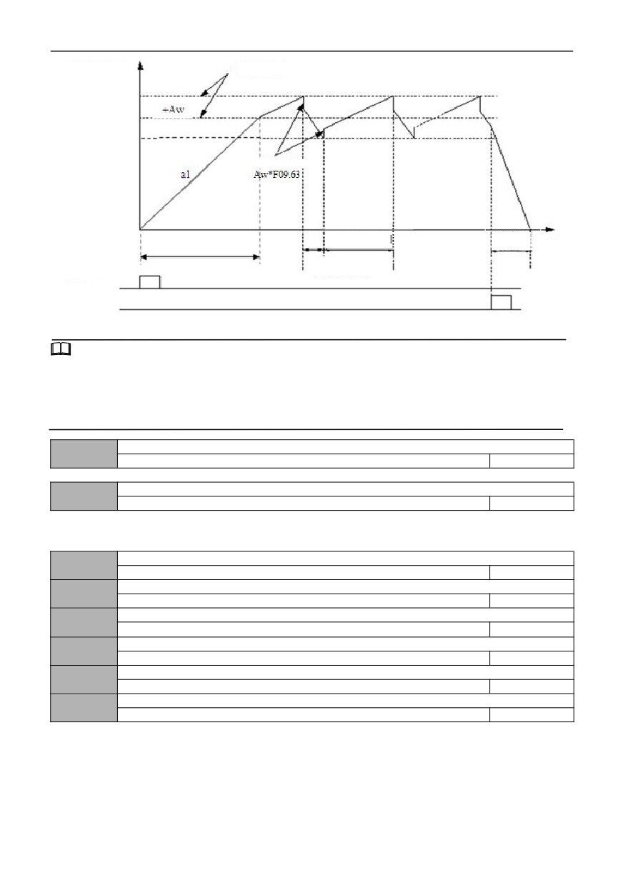
Swing frequency control is suitable for textile, chemical fiber and other industries, as well as occasions requiring traverse
and winding functions. Its typical work is shown in Figure F9-6.
Generally, the swing frequency process is as follows: first accelerate to the preset swing frequency (09.60) according to the
acceleration time, wait for a period of time (09.61), then transition to the center frequency according to the acceleration and
deceleration time, and then set the swing frequency amplitude (09.62), sudden jump frequency (09.63), swing frequency
rising time (09.64) and swing frequency falling time.
107
Operating frequency
Swing amplitude
Swing frequency upper
limit frequency
Center
Frequency swing
frequency lower limit
frequency
Jump frequency
Accelerates according to
Swing frequency
Deceleration timeaccording to
acceleration and
acceleration and deceleration time
rising time
deceleration time
Time
Swing frequency
falling time
Run command
Stop command
Fig. F9-6 Schematic diagram of Swing frequency
Tips:
1: the center frequency can be given by digital given frequency, analog quantity, pulse, PLC or multi-speed etc.
2: Automatic cancellation of frequency swing during JOG and closed-loop operation.
3: PLC runs with swing frequency. When switching between PLC sections, the swing frequency fails. After transitioning to
the set frequency of PLC according to the acceleration and deceleration setting of PLC stage, the swing frequency starts,
and when stopping the machine, it slows down according to the deceleration time of PLC stage.
Reservation
09.66
Reservation
0
Fixed length control
09.67
0~1
0
0: prohibited
1: valid
Set length
09.68
0.000~65.535(KM)
0.000
Actual length
09.69
0.000~65.535(KM)
0.000
Length magnification
09.70
0.100~30.000
1.000
Length correction coefficient
09.71
0.01~1.000
1.000
Measure the circumference of shaft
09.72
0.10~100.00CM
10.00
Number of pulses per rotation of shaft (DI6)
09.73
1~65535
1000
This set of functions is used to realize the fixed-length shutdown function.
The inverter inputs counting pulses from the terminal (HDI is defined as function 47), and the calculated length
is obtained according to the number of pulses per revolution of the speed measuring shaft (09.73) and the circumference of
the shaft (09.72).
Calculation length = count pulse number ÷ Number of pulses per revolution × Measure the circumference of shaft
The calculated length is corrected by length magnification (09.70) and length correction coefficient (09.71), and the actual
length is obtained.
108
Actual length = calculated length × Length magnification ÷ Length correction factor
When the actual length (09.69) ≥ the set length (09.68), the inverter will automatically issue a shutdown instruction to stop.
The actual length (09.69) should be cleared or modified before running again < Set the length (09.68), otherwise it will not
start.
Tips:
The actual length can be cleared with multi-function input terminal (the input terminal is defined as 46 functions, and
the length count is cleared). If the terminal is valid, the previous length count value will be cleared, and the actual length
can be counted and calculated normally after the terminal is disconnected.
The actual length is 09.69, which is automatically stored when power is cut off.
When the set length 09.68 is 0, the fixed-length shutdown function is invalid, but the length calculation is still valid.
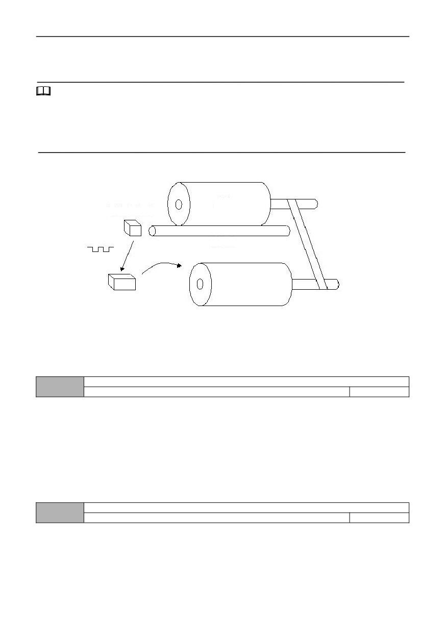
Application example of fixed-length shutdown function:
Spindle
Speed sensor
Speed measuring shaft
Motor
Inverter
Figure F9-7 Example of Long Stop Function
In Figure F9-7, the inverter drives the motor, which drives the spindle shaft to rotate through the conveyor belt, and
the speed measuring shaft contacts the spindle, so that the linear speed of the spindle is detected and transmitted to the
inverter through the counting terminal in the form of pulses. The inverter detects the pulses and calculates the actual length.
When the actual length is greater than or equal to the set length, the inverter automatically stops.
010 Group- Protective parameters
Motor Overload protection selection
10.00
0~2
1
0: prohibited
No motor overload protection (use it with caution).
1: Ordinary motor (electronic thermal relay mode, low-speed compensation)
due to the poor heat dissipation effect of ordinary motor in low-speed operation, the corresponding motor thermal
protection
value should also be adjusted appropriately. The low-speed compensation characteristic
here is to lower the overload protection threshold of motor whose operating frequency is lower than 30Hz.
2. Variable frequency motor (electronic thermal relay mode, low speed without compensation)
Due to the heat dissipation of the frequency conversion special motor is not affected by the rotating speed, there is no
need to adjust the protection value during low-speed operation.
Motor overload protection coefficient
10.01
20.0% ~ 120.0%
100.0%
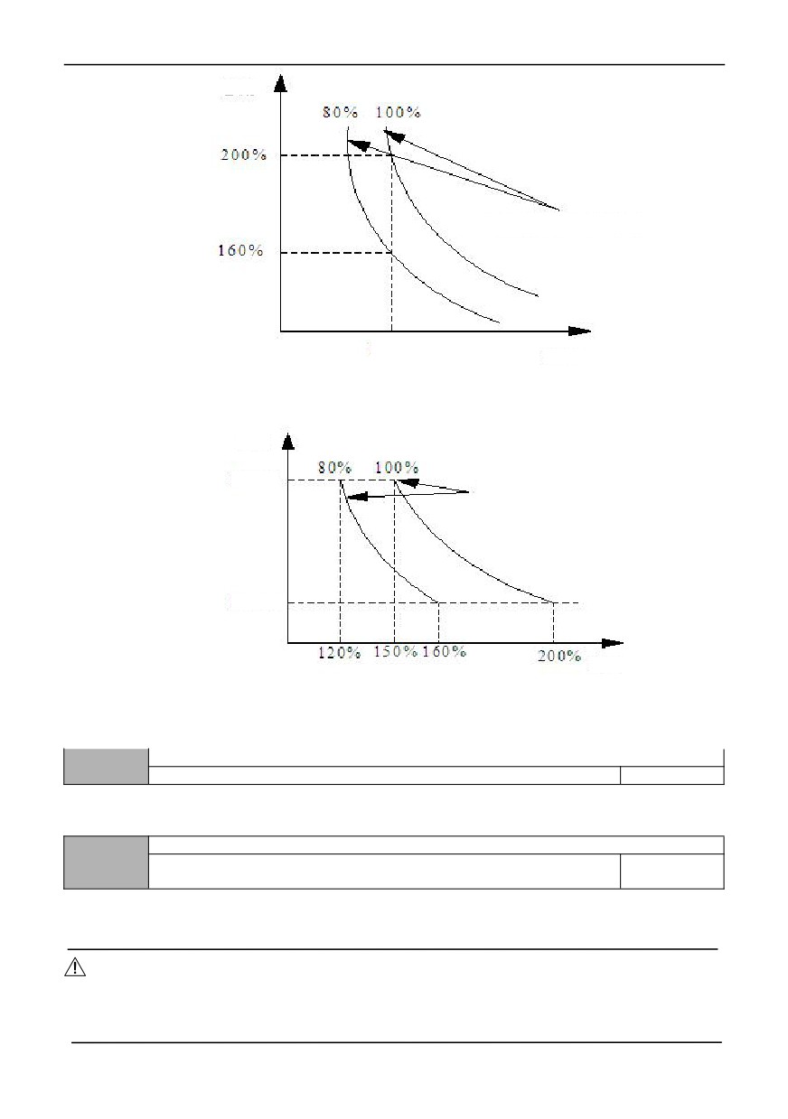
To implement valid overload protection for different types of load motors, it is necessary to set the overload protection
coefficient of motors reasonably and limit the maximum current allowed by the inverter. The motor overload protection
coefficient is the percentage of the rated current value of the motor to the rated output current value of the inverter.
When the inverter drives the motor with matching power level, the motor overload protection coefficient can be set to
100%. As shown in the figure below:
109
Current
Motor overload protection
coefficient
1 minute
Time
Figure 010-1 Motor overload protection curve
When the capacity of inverter is larger than that of motor, in order to implement valid overload protection for load
motors of different specifications, it is necessary to set the overload protection coefficient of motor reasonably as shown in
the following figure:
Time
1 hour
Motor overload protection
coefficient
1 minute
Current
Figure 010-2 Schematic diagram of motor overload protection coefficient setting
The motor overload protection coefficient can be determined by the following formula:
Overload protection coefficient of motor = maximum allowable load current/rated output current of inverter × 100%
Generally, the maximum load current refers to the rated current of the load motor. Adjustment of protection value in line.
Undervoltage protection action selection
10.02
0~1
0
0: prohibited
1: allowed (undervoltage is regarded as fault)
Undervoltage protection level
10.03
220V:180~280V
200V
Model setting
380V:330~480V
350V
This function code specifies the allowable lower limit voltage of DC bus when the inverter works normally.
Notes:
When the grid voltage is too low, the output torque of the motor will be decreased. For constant power load and
constant torque load, too low grid voltage will increase the input and output current of inverter, thus reducing the reliability
of inverter operation. Therefore, when operating for a long time under low grid voltage, the inverter power needs to be
derated.
110
Overvoltage limit level
10.04
220V:350~390V
370V
Model setting
380V:550~780V
660V
Overvoltage limit level defines the operating voltage during voltage stall protection.
Voltage limit coefficient during deceleration
10.05
0 ~ 100 0: Overvoltage stall protection is invalid
Model setting
During deceleration, the greater this value, the stronger the ability to suppress Overvoltage.
Current limit level (only V/F mode is valid)
10.06
G type: 80% ~ 200% * rated current of inverter
160%
Model setting
P type: 80% ~ 200% * rated current of inverter
120%
The current limiting level defines the current threshold of automatic current limiting operation, and its set value is the
percentage relative to the rated current of the inverter.
Notes:
In ordinary VF mode, limit amplitude with 10.06 during acceleration and constant speed operation; In vector VF mode,
the amplitude is limited by 10.06 during accelerated operation and infinite amplitude is processed during constant speed
operation; In vector mode, the amplitude limit in constant speed operation is only related to 04.20 ~ 04.21.
Selection of current limit in weak magnetic field
10.07
0~1
0
0: limited by the current limit level of 10.06
When the output frequency is within 50Hz, the amplitude is limited by 10.06.
1: limited by the current limit level converted from 10.06
When the output frequency is greater than 50Hz, the amplitude is limited by the current converted from 10.06.
Current limiting coefficient during acceleration
10.08
0 ~ 100 0: Acceleration current limit is invalid
Model setting
In the process of acceleration, the greater this value, the stronger the ability to suppress overcurrent.
Current limiting coefficient during constant speed
10.09
0~5000
40
0 ~ 100 is automatic frequency reduction, and the larger the coefficient, the faster the frequency reduction rate; 101 ~
5000 means manual frequency reduction, 101 means 0.01Hz /S, and so on, and 5000 means 50.00/s.
Drop load detection time
10.10
0.1S~60.0S
5.0
Drop load detection level
10.11
0.0 ~ 100.0% * rated current of inverter
0.0%
0: the off load drop detection is invalid
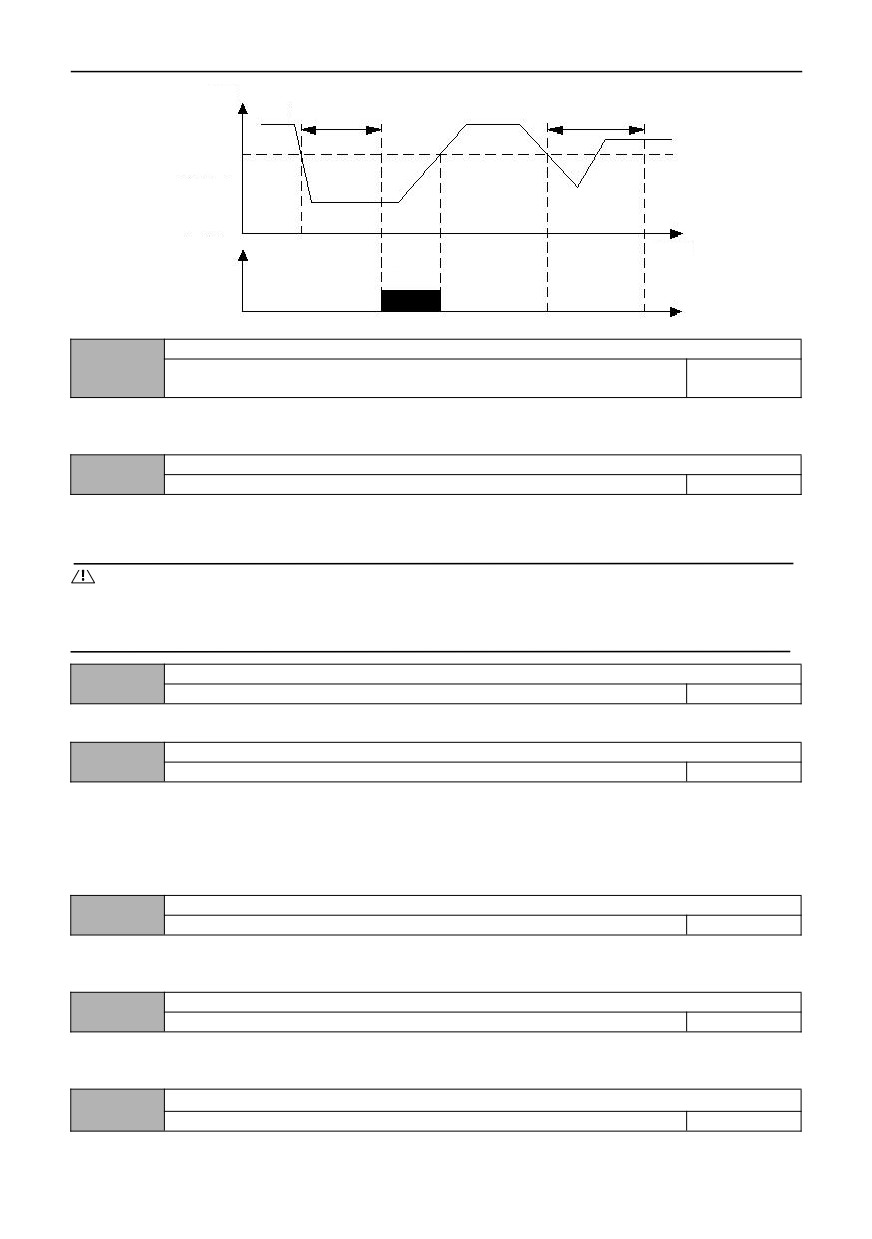
The off load detection level (10.11) defines the current threshold for the drop load action, which is set as a percentage
relative to the inverter rated current.
The off load detection time (10.10) defines that the output current of the inverter is less than the load drop detection
level (10.11) for more than a certain time, and then the load drop signal is output.
The off-load status is valid, that is, the working current of the inverter is less than the off-load detection level and the
holding time exceeds the off-load detection time.
111
Output
current
Drop-load detection time
Drop-load detection time
Drop-load
detection
level
Drop-load
Time
detection
action
Effective
Figure 010-3 Schematic diagram of drop load detection
Overload pre-alarm level
10.12
G type: 20% ~ 200% * rated current of inverter
160%
Model setting
P type: 20% ~ 200% * rated current of inverter
120%
Overload pre-alarm mainly monitors overload condition before overload protection of inverter. Overload pre-alarm level
defines the current threshold of overload pre-alarm action, and its set value is relative to the rated current of inverter.
Overload pre-alarm delay time
10.13
0.0~300s
10.0
Overload pre-alarm delay defines the delay time between the output current of inverter continuously exceeding the
amplitude of overload pre-alarm level (10.12) and the output of overload pre-alarm signal.
Notes:
By setting the parameters 10.12 and 10.13, when the output current of the inverter is greater than the overload
pre-alarm level amplitude (10.12), the inverter outputs the pre-alarm signal after delay (10.13), that is, the keypad displays
A-09.
Temperature detection threshold
10.14
0.0℃ ~ 90.0℃
65.0℃
See function description No.51 in parameter 07.18 ~ 07.21 for details.
Selection of input and output phase lose protection
10.15
0~3
Model setting
0: all prohibited
1: input prohibited, output allowed
2: Input allowed, output prohibited
3: All allowed
Manufacturer default option 1 for up to 7.5kW and above 11kW Manufacturer default option 3.
Input phase loss protection delay time
10.16
0.0S~30.0S
1.0
When the input phase lose protection is selected to be valid and the input phase lose fault occurs, the inverter will
protect E-12 after the time defined in 10.16, and stop freely.
Output phase lose protection detection reference
10.17
0% ~ 100% * rated current of inverter
50%
When the actual output current of the motor is greater than the rated current * [10.17], if the output phase failure
protection is valid, after a delay time of 5S, the inverter protection acts [E-13] and stops freely.
Output current unbalance detection coefficient
10.18
1.00~10.00
1.00
112
If the ratio of the maximum value to the minimum value in the three-phase output current is greater than this coefficient,
and the duration exceeds 10 seconds, the inverter will report the output current imbalance fault E-13. When 10.08 = 1.00,
the output current unbalance detection is invalid.
Reservation
10.19
Reservation
0
Treatment of PID feedback disconnection
10.20
0~3
0
0: no action
1: Alarm and keep running at the frequency of disconnection time
2: Protective action and free parking
3: Alarm and slow down to zero speed according to the set mode
Feedback disconnection detection value
10.21
0.0~100.0%
0.0%
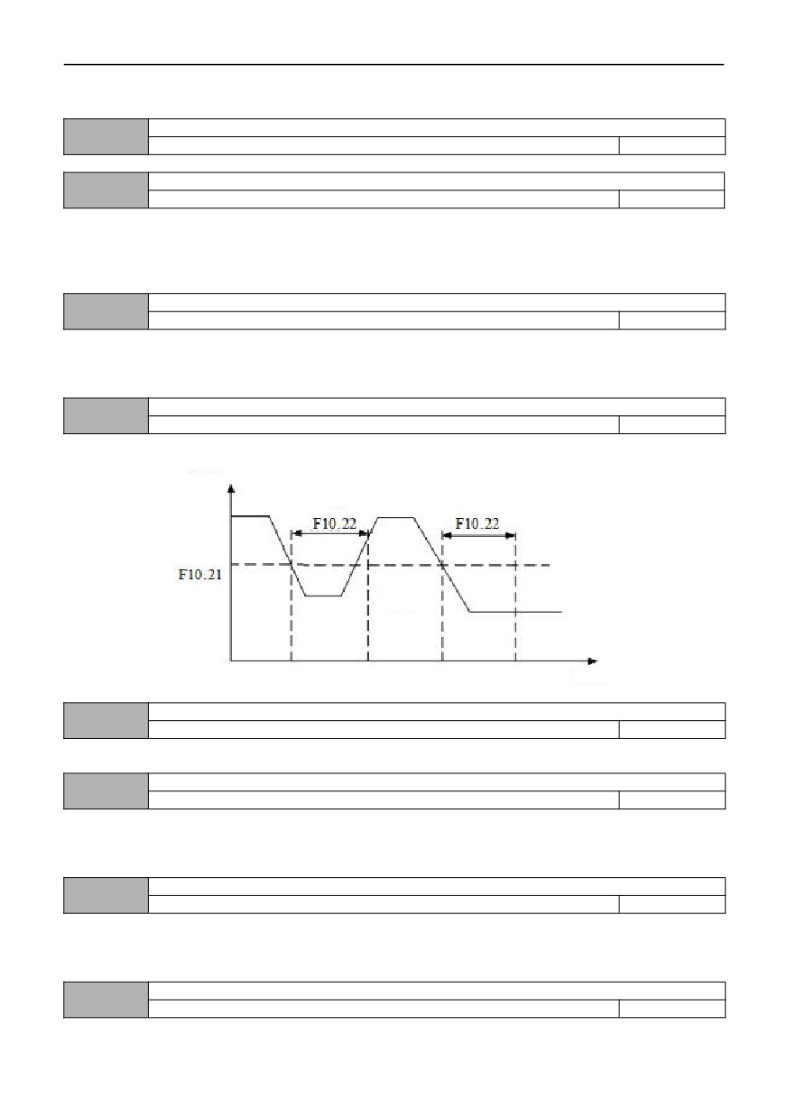
The maximum value given by PID is taken as the upper limit value of feedback disconnection detection value. In the
feedback disconnection detection time, when the feedback value of PID is continuously less than the feedback
disconnection detection value, the inverter will make corresponding protection actions according to the setting of 10.20.
Feedback disconnection detection time
10.22
0.0~3600.0S
10.0
Feedback the duration after disconnection and before protection action.
Closed-loop
feedback
value
Detection
value
Loss does
Loss
Loss
detection
not detect
detection
Time
Figure 010-4 Closed-loop feedback loss detection timing diagram
Setting of FDT1 current detection level
10.23
0.0~200.0%
0.0
See function No.62 in 07.18 ~ 07.21 for details.
Selection of RS485 communication abnormal action
10.24
0~2
1
0: protection action and free stop
1: Alarm and maintain the status quo to continue running
2: Alarm and shut down according to the set shutdown mode
RS485 communication timeout detection time
10.25
0.0~100.0s
5.0
If RS485 communication fails to receive the correct data signal within the time interval defined by this function code, it
is considered that RS485 communication is abnormal, and the inverter will make corresponding actions according to the
setting of 10.24. When this value is set to 0.0, RS485 communication timeout detection is not performed.
Keypad communication abnormal action selection
10.26
0~2
1
113
0: protection action and free stop
1: Protect actions and maintain the status quo to continue running
2: Protection action and shutdown according to the set shutdown mode
Keypad communication timeout check-out time
10.27
0.0~100.0s
1.0
If the keypad communication fails to receive the correct data signal within the time interval defined by this function
code, it is considered that the keypad communication is abnormal, and the inverter will make corresponding actions
according to the setting of 10.26.
EEFROM reading and writing error action selection
10.28
0~1
0
0: protection action and free stop
1: Alarm and continue running
Motor overload protection threshold
10.29
0 ~ 200% * rated current of motor
150%
Motor overload protection detection time
10.30
0~60000S
100
When 10.00 ten bits are 2, the output current reaches the overload protection threshold of the inverter (10.31), and
then delays the overload protection detection time of the inverter (10.32), and then reports the overload of the inverter E-09.
Inverter overload protection threshold
10.31
0 ~ 200% * rated current of inverter
150%
Inverter overload protection detection time
10.32
0~60000S
60
When 10.00 ten bits are 2, the output current reaches the overload protection threshold of the inverter (10.31), and
then delays the overload protection detection time of the inverter (10.32), and then reports the overload of the inverter E-09.
OC and module fault limit reset times
10.33
0~9999
5
When the failure times of OC and module exceed this set value, it needs to be powered on again before resetting.
Selection of encoder frequency modulation start bit
10.34
0~3
1
0: LED bits
1: LED ten bits
2:LED hundred bits
3: LED thousand bits
Reserved
10.35
0
0
011 Group-RS485 communication parameters
Protocol selection
11.00
0~1
0
Communication protocol selection
0:MODBUS
1:Automatic
Local address
11.01
0~247
1
0: Broadcast address
1~247:Slave station
114
During 485 communication, this function code is used to identify the address of the inverter.
Notes:
11.01 set 0 as the broadcast address, which can only receive and execute the commands of the upper computer, but will
not answer the upper computer.
Communication baud rate setting
11.02
0~5
3
0:2400BPS
1:4800BPS
2:9600BPS
3:19200BPS
4:38400BPS
5:115200BPS
This function code is used to define the data transmission rate between the upper computer and the inverter. The baud
rate set by the upper computer and the inverter should be consistent, otherwise the communication cannot be carried out.
The greater the baud rate is set, the faster the data communication is. However, setting too much will affect the stability of
communication.
Data format
11.03
0~5
0
0: No check(N, 8, 1)for RTU
1:Parity check (E, 8, 1)for RTU
2: Odd check (0,8,1) for RTU
3: No check (N, 8, 2)for RTU
4: Parity check (E, 8, 1)for RTU
5: Odd check (0,8,2) for RTU
Note: ASCII mode is temporarily reserved
The data format set by the upper computer and the inverter should be consistent, otherwise normal communication will not
be possible.
Local machine response delay
11.04
0~200ms
5
This function code defines the intermediate time interval between receiving the data frame of the inverter and sending
the response data frame to the upper computer. If the response time is less than the system processing time, the system
processing time shall prevail. If the delay is greater than the system processing time, after the system processes the data, it
will wait for a delay until the response delay time expires before sending the data to the upper computer.
Transmission response processing
11.05
0~1
0
0: Write operation has response
The inverter responds to all read and write commands of the upper computer.
1: Write operation does not respond
The inverter responds to all the read commands of the upper computer, but does not respond to the write
commands, so as to improve the communication efficiency.
Proportional linkage coefficient
11.06
0.01~10.00
1.00
This function code is used to set the weight coefficient of the frequency command received by inverter as slave
through the RS485 interface. The actual operating frequency of the machine is equal to the value of this function code
multiplied by the frequency setting command value received through the RS485 interface. In linkage control, this function
code can set the ratio of operating frequency of multiple inverters.
Communication function selection
11.07
00~21
00
LED bits: Communication mode selection
115
0: General model
1~4: Reserved
LED ten bits: Broadcast frequency source selection
0: Host set frequency
1: Host frequency source A
2: Host frequency source B
LED hundred bits: Reserved
LED thousand bits: Reserved
Communication display selection
11.08
0000~4444
000
LED bits: Communication bus voltage display selection
0: Normal display
1: Magnify 10 times
2: Magnify 100 times
3:Shrink 10 times
4:Shrink 100 times
Led ten bits: Communication current display selection
0: Normal display
1: Magnify 10 times
2: Magnify 100 times
3:Shrink 10 times
4:Shrink 100 times
LED hundred-digit: Operation frequency display selection
0: Normal display
1: Magnify 10 times
2: Magnify 100 times
3:Shrink 10 times
4:Shrink 100 times
LED thousand bits: Reserved
012 Group -Advanced functions and performance parameters
Energy consumption braking function setting
12.00
0~2
1
0: Invalid
1: Valid in the whole process
2: Valid only when decelerating
Energy consumption braking starting voltage
12.01
220V:340~380V
360V
Model setting
380V:660~760V
680V
Energy consumption braking return difference voltage
12.02
220V:10~100V
5V
Model setting
380V:10~100V
10V
Energy consumption braking action ratio
12.03
10~100%
100%
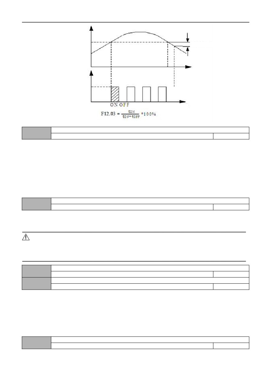
The above function codes are used to set the voltage threshold value, return difference voltage value and brake unit
utilization rate of the built-in brake unit of the inverter. If the internal DC side voltage of the inverter is higher than the
starting voltage of energy consumption braking, the built-in braking unit will act. If a braking resistor is connected at this
time, the internal pumping voltage energy of the inverter will be released through the braking resistor to reduce the DC
voltage. When the DC side voltage drops to a certain value (starting voltage-brake backlash), the built-in brake unit is
turned off.
116
Bus voltage
Starting voltage
Braking backlash
Time
Braking signal
Time
Figure 012-1 Schematic diagram of energy consumption braking
Power failure restart settings
12.04
0~2
0
0: Prohibited
When the power is turned on after power failure, the inverter will not run automatically.
1: Starting from starting frequency
When the power is turned on after power failure, if the starting conditions are met, the inverter will automatically start
running from the starting frequency point after waiting for the time defined in 12.05.
2: Speed tracking starting
When the power is turned on after a power failure, if the starting conditions are met, the inverter will automatically start and
run in speed tracking mode after waiting for the time defined in 12.05.
Waiting time for restart after power failure
12.05
0.0~60.0S
5.0
During the waiting time for restart, any operation command entered is invalid. If the shutdown command is input, the
inverter will automatically release the speed tracking restart state and return to the normal shutdown state.
Notes:
1: The valid restart after power failure is also related to the setting of 10.02. At this time, 10.02 must be set to 0.
2: This parameter will cause unexpected motor starting, which may cause potential damage to equipment and personnel.
Please use it with caution.
Automatic fault reset times
12.06
0~100
0
Automatic fault reset interval time
12.07
0.1~60.0S
3.0
100: Means unlimited times, that is, countless times
After a fault occurs during operation, the inverter stops outputting and displays the fault code. After the reset interval
set in 12.07, the inverter automatically resets the fault and restarts the operation according to the set starting mode.
The number of automatic fault resets is set by 12.06.When the number of fault reset is set to 0, there is no automatic reset
function and can only be reset manually. When 12.06 is set to 100, it means that the number of times is unlimited, that is,
countless times.
For IPM faults, external equipment faults, etc., the inverter is not allowed to conduct self-reset operation.
Cooling fan control
12.08
0~1
0
0: Automatic control mode
1: The power on process runs all the time
117
Password for running restricted function
12.09
0~65535
0
By default, the password is 0 ,and 12.10 and 12.11 items can be set; When there is a password, 12.10 and 12.11 can
only be set after the password is verified correctly.
When there is no need to operate the limit password function, the function code is set to 0.
ENTER
When setting the operation limit password, enter five digits, press the
key to confirm, and the password
will automatically take effect after one minute.
When you need to change the password, select 12.09 function code, press theENTER
key to enter the password
verification state, enter the modification state after the password verification is successful, enter the new password, press
theENTER
key to confirm, the password change is successful, and the password will automatically take effect after
one minute; Clear the password and set the running limit password to 0000.
Selection for running restricted function
12.10
0~1
0
0: Prohibited
1: Valid
When limiting the operation, as long as the cumulative operation time of the inverter exceeds the time set in 12.11, the
inverter protection acts and stops freely, and the operation panel will display E-26(RUNLT). If you want to clear the fault,
just verify 12.09 (operation restriction password) correctly, and then set 12.10 (operation restriction function selection) to 0
(invalid)to clear the operation restriction fault.
Run limit time
12.11
0~65535h
0
Note: This function parameter cannot be initialized. Please refer to 12.09 for details
Frequency drop point at instantaneous power failure
12.12
220V:180V~330V
250V
Model setting
380V:300V~550V
450V
If the inverter bus voltage drops below 12.12* rated bus voltage, and the instantaneous stop control is valid, the
instantaneous stop starts to act.
Frequency drop coefficient of instantaneous power failure
12.13
1 ~ 100 0: The instantaneous stop function is invalid
0
Droop control
12.14
0.00~10.00HZ
0.00
0.00: The droop control function is invalid
When multiple inverters drive the same load, the load distribution is unbalanced due to different speeds, which makes
the inverters with higher speed bear heavier loads. The droop control characteristic is that the speed droop changes with
the increase of load, which can make the load distribution balanced; This parameter adjusts the frequency variation of the
frequency converter with droop speed.
When 00.15=1 (high frequency mode), the upper limit of the value of this function code is 100.0Hz.
Speed tracking waiting time
12.15
0.1~5.0S
1.0
Before the inverter speed tracking starts, it will start tracking after this delay.
Speed tracking current limiting level
12.16
80% ~ 200% * rated current of inverter
100%
In the process of speed tracking, this function code plays the role of automatic current limiting. When the actual current
reaches the threshold (12.16), the inverter will reduce the frequency and limit the current, and then continue to track and
accelerate; The set value is a percentage of the rated current of the inverter.
Speed tracking speed
12.17
1~125
25
118
When the speed tracking restarts, select the speed of speed tracking. The smaller the parameter, the faster the
tracking speed. But too fast may lead to unreliable tracking.
PWM mode
12.18
0000~1311
001
Led bits: PWM synthesis mode
0: Full frequency seven segments
The current output is stable, and the calorific value of the full-band power tube is large.
1: Seven segments to five segments
The current output is stable, the calorific value of low-frequency power tube is large, and the calorific value of
high-frequency power tube is small.
LED Ten bits: PWM temperature correlation
0: Invalid
1: Valid
This function selection is valid. If the radiator temperature reaches the warning value (50 ℃ ) ,the inverter will
automatically reduce the carrier frequency until the radiator temperature no longer exceeds the warning value.
LED hundred-bits: PWM frequency correlation
0: All invalid
1: Low frequency adjustment,High frequency adjustment
2: Low frequency doesn't adjust,High frequency adjustment
3: Low frequency adjustment,High frequency doesn't adjust
When the PWM temperature is associated, after the radiator temperature reaches the warning value (50 ° C), if the low
frequency and high frequency are not adjusted, the carrier frequency remains unchanged; if the low frequency and high
frequency are adjusted, the inverter will automatically reduce the carrier frequency.
LED Thousands: Flexible PWM function.
0:Invalid
1:Valid
When this function selection is valid, the electromagnetic interference and motor noise can be reduced by changing
the implementation mode of PWM.
Voltage control function
12.19
0000~3112
2112
LED bits: AVR function
0:Invalid
1:Valid throughout
2:Invalid only when decelerating
AVR is the automatic voltage regulation function. When there is a deviation between the input voltage and the rated value
of the inverter, this function can keep the output voltage of the inverter constant to prevent the motor from operating in an
overvoltage state. This function is invalid when the output command voltage is greater than the input power supply voltage.
In the deceleration process, if the AVR does not act, the deceleration time is short, but the running current is large; The
AVR acts, the motor decelerates smoothly, the running current is small, but the deceleration time is long.
Voltage
Voltage
Output voltage when AVR is disabled
Output voltage after
Input voltage
AVR function
Rated voltage
Time
Time
Figure 012-2 Function Diagram of AVR
119