HV100 Series Frequency Inverter. User Manual (V4.0) - page 5
AI2 input corresponding physical quantity
06.06
0~2
0
0: Speed command (output frequency,-100.0% ~ 100.0%)
1: Torque command (output torque,-200.0% ~ 200.0%)
AI2 analog setting regards as a given value of torque command, and the given torque range can be -200.0% ~
200.0%. Please refer to F6 group’s detailed function description for related settings.
2: Voltage command (output voltage, 0.0% ~ 200.0% * rated voltage of motor)
AI2 input lower limit
06.07
0.00V~10.00V
0.00
AI2 lower limit corresponds to physical quantity setting
06.08
-200.0% ~ 200.0%
0.0%
AI2 input upper limit
06.09
0.00V~10.00V
10.00
AI2 upper limit corresponds to physical quantity setting
06.10
-200.0% ~ 200.0%
100.0%
AI2 input filter time
06.11
0.00S~10.00S
0.05
The above function codes define the input ranges of analog input voltage channels AI1 and AI2 and their
corresponding physical quantity percentages and filtering time constants. Among them, AI2
can be selected as
voltage/current input through J1 jumper, and its digital setting can be set according to the relationship between 0 ~ 20mA
and 0 ~ 10v. The specific setting should be based on the actual situation of the input signal.
The input filtering time constants of AI1 and AI2 are mainly used for filtering processing of analog input signals to
eliminate the influence of interference. The larger the time constant, the stronger the anti-interference ability, the more
stable the control, but the slower the response; On the contrary, the smaller the time constant, the faster the response, but
the weaker the anti-interference ability, and the control may be unstable. If the optimal value cannot be determined in
practical application, the value of this parameter should be appropriately adjusted according to whether the control is stable
or not and the situation of response delay.
Analog input anti-shake deviation limit
06.12
0.00V~10.00V
0.10
When the analog input signal fluctuates frequently near a given value, the frequency fluctuation caused by this
fluctuation can be suppressed by setting 06.12.
Zero frequency operation threshold
06.13
Zero frequency return difference ~ 50.00Hz
0.00
When 00.15=1 (high frequency mode), the maximum value of this function code is 500.0Hz.
Zero frequency return difference
06.14
0.00 ~ zero frequency operation threshold
0.00
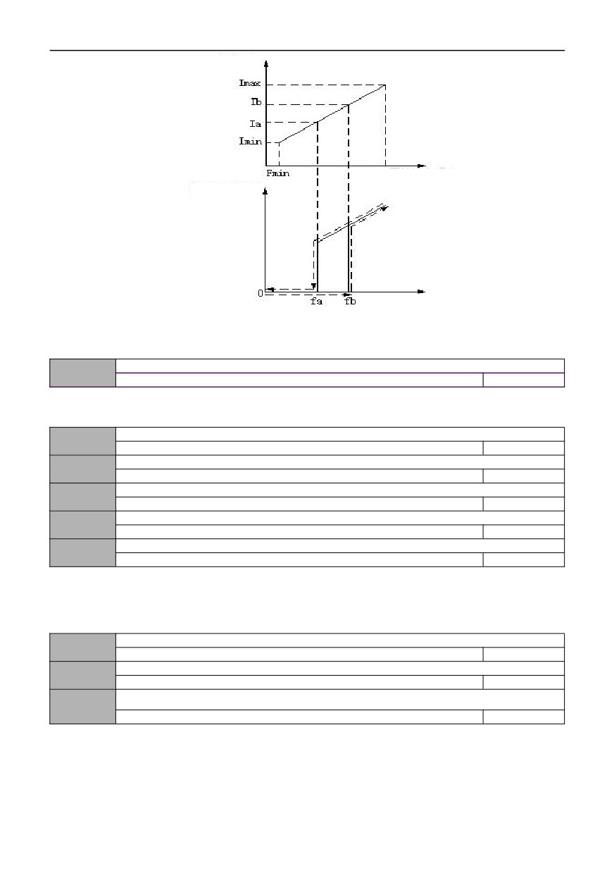
These two function codes are used to set the zero frequency return control function. Take the analog AI1 current given
channel as an example, as shown in Figure F6-1.
Starting process:
After the running command is issued, only when the analog AI1 current input reaches or exceeds a certain value Ib
and its corresponding stated frequency reaches fb, the motor starts to start and accelerates to the frequency corresponding
to the simulated AI1 current input according to the acceleration time.
Shutdown process:
In the process of running, when the current value of AI1 is reduced to Ib, the inverter will not stop immediately, and
only when the current of AI1 continues to decrease to Ia and the corresponding stated frequency is fa, will the inverter stop
outputting. Here, fb is defined as zero frequency operation threshold, which is defined by 06.13, and the value of fb-fa is
defined as zero frequency return difference, which is defined by function code 06.14.
With this function, the sleep function can be completed, the energy-saving running can be realized, and the inverter
can be prevented from starting frequently at the threshold frequency through the width of the return difference.
80
AI2 Current Input
Fmax Original Setting Frequency
Actual Set
Frequency
Original Setting Frequency
fb :Zero frequency operation threshold
fa: fb - zero frequency return difference
Figure F6-1 Schematic diagram of zero frequency function
External pulse input corresponds to physical quantity
06.15
0~1
0
0: Speed command (output frequency,-100.0% ~ 100.0%)
1: Torque command (output torque,-200.0% ~ 200.0%)
Lower limit of external pulse input
06.16
0.00~50.00kHz
0.00
The lower limit of external pulse corresponds to the setting of physical quantity
06.17
-200.0% ~ 200.0%
0.0%
upper limit of external pulse input
06.18
0.00~50.00kHz
50.00
The upper limit of external pulse corresponds to the setting of physical quantity
06.19
-200.0% ~ 200.0%
100.0%
External pulse input filtering time
06.20
0.00S~10.00S
0.05
The above function code defines the input range of the pulse input channel and the corresponding physical quantity
percentage. At this time, the multi-function terminal DI6 must be defined as the ‘pulse frequency input’ function.
The pulse input filtering time constant is mainly used for filtering process of the pulse signal. The principle is the same
as the analog input filtering time constant.
Function Selection of AO1 multifunctional Analog Output Terminal
06.21
0 -14
0
Function Selection of AO2 multifunctional Analog Output Terminal
06.22
0-14
4
Function selection of HDO multifunctional pulse output terminal
06.23
0 -14
11
The above function codes determine the corresponding relationship between multifunctional analog output terminal AO
and pulse output terminal HDO and various physical quantities, as shown in the following table:
81
HV100
Series High Performance Current Vector Inverter
Item
AO
Scope of project
Upper limit of 0v/0ma ~ AO
0~ Max output frequency
Output frequency (before slip
compensation)
Upper limit of 2V/4mA~AO
0~ Max output frequency
Output frequency
(after slip
Upper limit of 0V/0mA~AO
0~ Max output frequency
compensation)
Upper limit of 2V/4mA~AO
0~ Max output frequency
Upper limit of 0V/0mA~AO
0~ Max output frequency
Set frequency
Upper limit of 2V/4mA~AO
0~ Max output frequency
Upper limit of 0V/0mA~AO
0 ~ synchronous speed of motor
Revolving speed of motor
Upper limit of 2V/4mA~AO
0 ~ synchronous speed of motor
Upper limit of 0V/0mA~AO
0~2 times rated current
Output current
Upper limit of 2V/4mA~AO
0~2 times rated current
Upper limit of 0V/0mA~AO
0~1.2 times rated Output voltage
Output voltage
Upper limit of 2V/4mA~AO
0~1.2 times rated Output voltage
Upper limit of 0V/0mA~AO
0~800V
Bus voltage
Upper limit of 2V/4mA~AO
0~800V
Upper limit of 0V/0mA~AO
0V/0mA~10V/20mA
PID given quantity
Upper limit of 2V/4mA~AO
0V/0mA~10V/20mA
Upper limit of 0V/0mA~AO
0V/0mA~10V/20mA
PID feedback quantity
Upper limit of 2V/4mA~AO
0V/0mA~10V/20mA
Upper limit of 0V/0mA~AO
0V/0mA~10V/20mA
AI1
Upper limit of 2V/4mA~AO
0V/0mA~10V/20mA
Upper limit of 0V/0mA~AO
0V/0mA~10V/20mA
AI2
Upper limit of 2V/4mA~AO
0V/0mA~10V/20mA
Upper limit of 0V/0mA~AO
0~50KHZ
Frequency of Input pulse
Upper limit of 2V/4mA~AO
0~50KHZ
Upper limit of 0V/0mA~AO
0~2 times rated current
Torque current
Upper limit of 2V/4mA~AO
0~2 times rated current
Upper limit of 0V/0mA~AO
0~2 times rated current
Magnetic flux current
Upper limit of 2V/4mA~AO
0~2 times rated current
Upper limit of 0V/0mA~AO
0% ~ 100% * AO upper limit value
communication settings
Upper limit of 2V/4mA~AO
0% ~ 100% * AO upper limit value
The range of HDO is from the lower limit of HDO ~HDO upper limit, which corresponds to the lower limit and upper
limit of each physical quantity in the above table.
AO1 output lower limit corresponds to physical quantity
06.24
-200.0% ~ 200.0%
0.0%
AO1 output lower limit
06.25
0.00~10.00V
0.00
AO1 output upper limit corresponds to physical quantity
06.26
-200.0% ~ 200.0%
100.0%
AO1 output upper limit
06.27
0.00~10.00V
10.00
AO2 output lower limit corresponds to physical quantity
06.28
-200.0% ~ 200.0%
0.0%
82
AO2 output lower limit
06.29
0.00~10.00V
0.00
AO2 output upper limit corresponds to physical quantity
06.30
-200.0% ~ 200.0%
100.0%
AO2 output upper limit
06.31
0.00~10.00V
10.00
DO output lower limit corresponding to physical quantity (reservation)
06.32
-200.0% ~ 200.0%
0.0%
Lower limit of DO output (reservation)
06.33
0.00~50.00kHz
0.00
DO output upper limit corresponding to physical quantity (reservation)
06.34
-200.0% ~ 200.0%
100.0%
DO output upper limit (reservation)
06.35
0.00~50.00kHz
50.00
AI multi-point curve selection
06.36
0000~011
0000
LED bit: AI1 multi point curve selection
0: Forbidden
1: Effective
LED10-dight: AI2 Multi point curve selection
0: Forbidden
1: Effective
LED100-dight: analog input signal selection
0: AI1 and AI2 input signals are 0 ~ 10V
1: AI1 input signal is 4 ~ 20mA, and AI2 input signal is 0 ~ 10V
2: AI2 input signal 4 ~ 20mA, AI1 input signal 0 ~ 10V
3: AI1 and AI2 input signals are 4 ~ 20mA
LED1000-dight: Reserved
AI1 curve minimum input
06.37
0.00~【06.39】
0.00
AI1 curve minimum input corresponding setting
06.38
-200.0% ~ 200.0%
0.0%
Note: the range is associated with 06.00
AI1 curve inflection point 1 input
06.39
【06.37】~【06.41】
3.00
AI1 curve inflection point 1 input corresponding setting
06.40
-200.0% ~ 200.0%
30.0%
Note: the range is associated with 06.00
AI1 curve inflection point 2 input
06.41
【06.39】~【06.43】
6.00
AI1 curve inflection point 2 input corresponding setting
06.42
-200.0% ~ 200.0%
60.0%
Note: the range is associated with 06.00
Maximum input of AI1 curve
06.43
【06.41】~10.00
10.00
AI1 curve maximum input corresponding setting
06.44
-200.0% ~ 200.0%
100.0%
Note: the range is associated with 06.00
AI2 curve minimum input
06.45
0.00~【06.39】
0.00
AI2 curve minimum input corresponding setting
06.46
-200.0% ~ 200.0%
0.0%
Note: the range is associated with 06.06
83
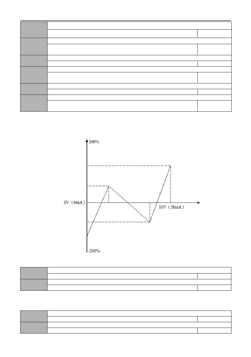
AI2 curve inflection point 1 input
06.47
【06.37】~【06.41】
3.00
AI2 curve inflection point 1 input corresponding setting
06.48
-200.0% ~ 200.0%
30.0%
Note: the range is associated with 06.06
AI2 curve inflection point 2 input
06.49
【06.39】~【06.43】
6.00
AI2 curve inflection point 2 input corresponding setting
06.50
-200.0% ~ 200.0%
60.0%
Note: the range is associated with 06.06
AI2 curve maximum input
06.51
【06.41】~10.00
10.00
AI2 curve maximum input corresponding setting
06.52
-200.0% ~ 200.0%
100.0%
Note: the range is associated with 06.06
The multi-point curves of AI1 and AI2 are selected by 06.36, and the corresponding relation of specific settings is
shown in Figure F6-2.
AI analog input
corresponds
setting quantity
AI curve
maximum input
corresponds
settings
AI curve inflection
point 1 input
corresponds
settings
AI analog input
AI curve inflection
voltage (current)
point 2
AI curve inflection
point 1
AI curve inflection
point 2 input
corresponding
settings
AI curve minimum
input corresponding
setting
Fig. F6-2 Schematic diagram of multi-point curve
AI1 input voltage protection upper limit
06.53
【06.54】~10.00V
6.80
AI1 input voltage protection lower limit
06.54
0.00V ~【06.53】
3.10
For details, please refer to the function description of No.57 (AI1 input overrun) in the function code 07.18 ~ 07.21.
007 group-digital input and output parameters
Input terminal DI1 function (when 00.01 is 2 or 3, the default function is 58)
07.00
0~65
1
Input terminal DI2 function (when 08.21 is not 0 value, the default function is 59)
07.01
0~65
2
84
Input terminal DI31 function (when 00.01 is 2 or 3, the default function is 60)
07.02
0~65
4
Input terminal DI4 function (when 00.01 is 2 or 3, the default function is 61)
07.03
0~65
7
Input terminal DI5 function (when 00.01 is 2 or 3, the default function is 62)
07.04
0~65
8
Input terminal DI6 function (when 00.01 is 2 or 3, the default function is 63)
07.05
0~65
0
HDI function of input terminal (high speed pulse input)
07.06
0~65
45
Reservation
07.07
—
0
0:
None
1:
Forward rotation control(FWD)
Terminal and COM short circuit, the inverter is running forward, only valid when 00.06=1.
2:
Reverse rotation control(REV)
Terminal and COM short circuit, inverter is running reversely, only valid when 00.06=1.
3: Three-wire control
Refer to the functional description of operation modes 2 and 3 (three-wire control modes 1 and 2) in 07.11.
4: Forward jog control
Terminal and COM short circuit, the inverter is forward jogging running, only valid when 00.06=1.
5: Reverse jog control
Terminal and COM short circuit, inverter reverse jogging running, only valid when 00.06=1.
6: Free stop control
This function has the same meaning as the free running shutdown defined in 01.08, but it is realized by
control
terminals here, which is convenient for remote control.
7: External reset signal input (RST)
When the inverter fails, the fault can be reset through this terminal. Its function is consistent with the function of
STOP/RESET
key. This function is valid under any command channel.
8: External equipment fault normally open (NO) input
9: External equipment fault normally close (NC) input
The fault signal of external equipment can be input through this terminal, which is convenient for the inverter to monitor
the fault of external equipment. After receiving the external equipment fault signal, the inverter displays E-19, that is, the
external equipment fault alarm. The fault signal can be input in two ways: normally open and normally closed.
10: Emergency stop function (brake at the fastest speed)
This function is used for emergency stop. The terminal is short-circuited with COM, and the emergency standby
deceleration time (01.36) is used to decelerate and brake.
11: Reservation
12: Frequency increment command
Terminals are short-circuited with COM, and the frequency increase, which is only valid when the frequency given
channel is digital given 2 (terminal UP/DOWN adjustment).
13: Frequency decrement command
Terminals are short-circuited with COM, and the frequency decreases, which is only valid when the frequency given
channel is digital given 2 (terminal UP/DOWN adjustment).
14: UP/DOWN terminal frequency is cleared
Clear the increment of digital frequency 2 (frequency adjusted by UP/DOWN terminal) through the terminal.
15: Multi-speed selection 1
16: Multi-speed selection 2
17: Multi-speed selection 3
18: Multi-speed selection 4
Up to 16 speeds can be selected by selecting the ON/OFF combination of these function terminals. As shown in the
table below:
85
Multi-speed
Multi speed
Multi speed
Multi speed
Segment
selection SS4
Selection SS3
Selection SS2
Selection SS1
speed
OFF
OFF
OFF
OFF
0
OFF
OFF
OFF
ON
1
OFF
OFF
ON
OFF
2
OFF
OFF
ON
ON
3
OFF
ON
OFF
OFF
4
OFF
ON
OFF
ON
5
OFF
ON
ON
OFF
6
OFF
ON
ON
ON
7
ON
OFF
OFF
OFF
8
ON
OFF
OFF
ON
9
ON
OFF
ON
OFF
10
ON
OFF
ON
ON
11
ON
ON
OFF
OFF
12
ON
ON
OFF
ON
13
ON
ON
ON
OFF
14
ON
ON
ON
ON
15
Output
frequency
15 speed
1 speed
Running command
Time
Figure F7-1 Schematic diagram of Multi speed operation
19: Acceleration or deceleration time selection TT1
20: Acceleration or deceleration time selection TT2
By selecting the ON/OFF combination of these functional terminals, you can choose up to four
acceleration/deceleration times. As shown in the table below:
Select terminal 2 for acceleration
Select terminal 1 for acceleration
Acceleration or deceleration time
and deceleration time
and deceleration time
selection
OFF
OFF
Acceleration time 1/ deceleration time 1
OFF
ON
Acceleration time 2/ deceleration time 2
ON
OFF
Acceleration time 3/ deceleration time 3
ON
ON
Acceleration time 4/ deceleration time 4
21: Running command channel selection 1
22: Running command channel selection 2
By selecting the ON/OFF combination of these functional terminals, you can choose up to three running command
channels and four ways. As shown in the table below:
86
Running command channel
Running command channel
Running command channel
selection terminal 2
selection terminal 1
OFF
OFF
Determined by function code 00.06
0: the operation panel runs the
OFF
ON
command channel
ON
OFF
1: terminal running command channel
2: communication running command
ON
ON
channel
23: Inverter Forbidden acceleration/deceleration command
When the terminal is valid, the inverter will not be affected by external signals (except shutdown command), and
maintain the current frequency running.
24: Inverter run forbidden command
When the terminal is valid, the inverter in operation is free to shut down, while starting is prohibited in standby state.
Mainly used for occasions requiring safety linkage
25: Switch to keypad run command
When the terminal is valid, the running command is forcibly converted from the current channel to the panel control,
the terminal is disconnected, and return to the previous running command channel.
26: Switch to terminal run command
When the terminal is valid, the running command is forcibly converted from the current channel to the terminal control,
the terminal is disconnected, and return to the previous running command channel.
27: Switch to communicate run command
When the terminal is valid, the running command is forcibly converted from the current channel to communication control,
the terminal is disconnected, and return to the previous running command channel.
28: Auxiliary frequency is cleared
Only valid for digital auxiliary frequency (00.08 = 0, 1, 2). When this function terminal is valid, the auxiliary frequency
will be cleared quantitatively, and the set frequency will be completely determined by the main given frequency.
29: Frequency source A switch to K*B
This terminal is valid. If 00.09 (frequency combination algorithm) selects 6, the given frequency channel will be forcibly
switched to frequency source B, and the given frequency channel will be restored to A after being invalid.
30: Frequency source A switch to A+K*B
This terminal is valid. If 00.09 (frequency combination algorithm) selects 7, the given frequency channel will be forcibly
switched to frequency source (A+k * B), and the given frequency channel will be restored to A after being invalid.
31: Frequency source A switch to A-K*B
This terminal is valid. If 00.09 (frequency combination algorithm) selects 8, the given frequency channel will be
forcibly switched to frequency source (A-k * B), and the given frequency channel will be restored to A after being invalid.
32:Reservation
33: PID control input
When the frequency given channel is PID given, and the PID input mode is manual input, the terminal is valid, and PID
running is entered. Please refer to F8 group parameter setting for detailed function codes.
34:PID control pause
Used to realize pause control of PID in running. When the terminal is valid, PID adjustment stops, and the frequency of
inverter stops running at the current frequency. After the terminal is invalid, PID adjustment will continue, and the operating
frequency will change with the change of adjustment amount.
35: Swing frequency control input
When the swing frequency starting mode is manual input, the swing frequency function is valid when the terminal is
valid. If it is invalid, it will run at the preset frequency of swing frequency. Please refer to the description of function code
09.55 ~ 09.65.
36: Swing frequency control pause
Terminal and COM short circuit, inverter pause the operation mode of swing frequency, and the frequency of inverter
stops running at the current frequency; After the terminal is invalid, continue to swing frequency running.
37: Swing frequency state reset
When this function is selected, whether in automatic or manual input mode, closing this terminal will clear the
frequency swing state information memorized in the inverter. After disconnecting this terminal, the swing frequency starts
again (if there is a preset frequency, run the preset frequency first). Please refer to the description of function code 09.55 ~
09.65.
38:PLC control input
When the PLC input mode is manually input through the defined multi-function terminal, the terminal is valid, and when
the operation command arrives, the PLC runs normally; If the terminal is invalid, when the running command arrives, it will
run at zero frequency.
39:PLC pause
It is used to realize pause control of the running PLC process. If the terminal is valid, the inverter runs at zero
frequency, and the PLC does not time; After the terminal is invalid, the inverter starts in the way of speed tracking, and
continues the PLC running. Please refer to the description of function code 09.00 ~ 09.53.
87
40: PLC reset
In the shutdown state of PLC operation mode, when this function terminal is valid, the information such as PLC operation
stage, operation time and operation frequency memorized by PLC shutdown will be cleared; After the function terminal is
invalid, the operation will be restarted. See F9 group function code description
41: Count clearance signal
Terminals are short-circuited with COM, and the internal counter is reset, which is used in conjunction with function No.42.
42: Counter trigger signal input
When a pulse is received at the counting pulse input port of the internal counter, the counting value of the counter
increases by 1 (if the counting mode is counting down, it decreases by 1), and the highest frequency of counting pulses is
200Hz. See description of function code 07.31 ~ 07.33 for details.
43 Timing trigger input
Trigger port of internal timer. See description of function code 07.35 ~ 07.36 for details.
44: Timing clearance signal
Terminals are short-circuited with COM, and the internal timer is reset, which is used in conjunction with function No.43.
45: External pulse frequency input (only valid for HDI-DI6)
The main frequency channel A selects the pulse input port with given pulse, which is only valid for DI6 and is set in
accordance with 00.07.
46: Length zero clearance
When this function terminal is valid, 09.69 (actual length) data will be cleared to prepare for recalculation of length.
Refer to 09.67 ~ 09.73 functional parameters.
47: Length count input (only valid for HDI-DI6)
It is only valid for multifunctional input terminal DI6, which receives pulse signals as a given length. Refer to 09.67 ~
09.73 group of functional parameters for the relationship between the number of input signal pulses and the length.
48: Speed and torque control switching
When the speed and torque control selection conditions are valid (terminal switching), the terminal is valid, then it is
torque control; If the terminal is invalid, it is speed control. Please refer to 04.10 ~ 04.11 for the setting of related function
codes, where 04.11 is the delay time of speed and torque switching.
49: Torque control is prohibited
Torque control mode of inverter is prohibited
50~55:Reservation
56~57:Reservation
58: Start/stop (manual)
When the terminal is valid, the frequency is given by AI1. PID control is not carried out, and it is controlled by
interlocking signal. The interlocking signal who puts into operation first starts first, and who puts into operation together
starts a small signal.
59: Operation permission (DI2)
This terminal is used to control the start and stop of inverter, which is generally controlled by external water shortage or
high voltage signal.
60: Interlock 1 (DI3)
After this terminal is connected, it is output corresponding to the open collector Y1.
61: Interlock 2 (DI4)
After the terminal is connected, it is output corresponding to the open collector Y2.
62: Interlock 3(DI5)
When this terminal is connected, it is output corresponding to the relay R1.
63: PFC start/stop (DI6)
When the terminal is valid, PID control is carried out, which is controlled by interlocking signals. The interlocking signal
who puts into operation first starts first, and who puts into operation together starts a small signal.
64: Frequency source A is switched to B and run
If the terminal is connected validly in the running state, the frequency is switched from A frequency source to B
frequency source; If the terminal is connected validly in the shutdown state, the frequency will be switched to the B
frequency source and runs.
65: The 1st group PID switch to the 2nd group PID
Times of D filtering
07.08
1~10
5
Used to set the sensitivity of the input terminal. If the digital input terminal is susceptible to interference and causes
misoperation, this parameter can be increased to enhance the anti-interference ability, but the sensitivity of the input
terminal will be reduced if the setting is too large.
Selection of terminal function detection when power on
07.09
0~1
0
88
0: the terminal operation command is invalid when power-on
In the process of power-on, even if the inverter detects that the operation command terminal is valid (closed), the
inverter will not start. Only when the terminal is closed again after disconnection can the inverter start.
1: the terminal operation command is valid when power on
In the process of power-on, the inverter can start when it detects that the terminal operation command terminal is valid
(closed).
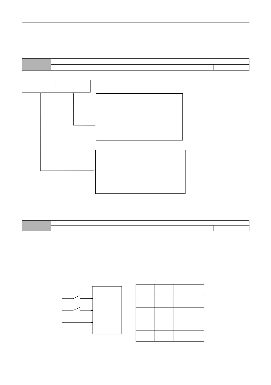
Input terminal valid logic setting (DI1~HDI)
07.10
0~7FH
00
Ten bits
bit
Bit0:DI1
terminal positive and negative
logic definition
Bit1:DI2
terminal positive and negative
logic definition
Bit2:DI3
terminal positive and negative
logic definition
Bit3:DI1
terminal positive and negative
logic definition
Bit4:DI5
terminal positive and negative
logic definition
Bit5:DI6
terminal positive and negative
logic definition
Bit6: HDI terminal positive and negative
logic definition
Bit7: reservation
0: Positive logic, that is, the connection between Xi terminal and common terminal is valid, and the disconnection is invalid
1: Anti-logic, that is, the connection between Xi terminal and common terminal is invalid, and the disconnection is valid
FWD/REV terminal control mode
07.11
0~3
0
This function code defines four different ways to control the running of inverter through external terminals.
0: Two-wire control mode 1
Xm: forward command (FWD), Xn: reverse command (REV), Xm and Xn represent any two terminals respectively
defined as FWD and REV functions in DI1-HDI. In this control mode, K1 and K2 can independently control the running and
direction of the inverter
Running
K1
K2
K1
instructions
Xm(FWD)
K2
0
0
Stop
Xn(REV)
0
1
Forward
COM
1
0
Stop
1
1
Reverse
Figure F7-2 Schematic diagram of two-wire control mode 1
89
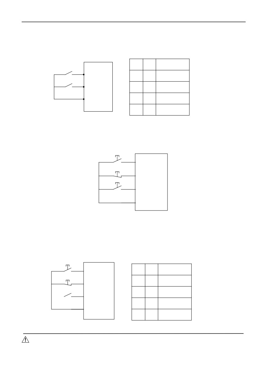
1: Two-wire control mode 2
Xm: forward command (FWD),Xn: Reverse command (REV), Xm and Xn represent any two terminals respectively
defined as FWD and rev functions in DI1-HDI. In this control mode, K1 is the running and stopping switch, and K2 is the
direction change switch.
Running
K1
K2
K1
instructions
Xm(FWD)
K2
0
0
Stop
Xn(REV)
0
1
Forward
COM
1
0
Stop
1
1
Reverse
Figure F7-3 Schematic diagram of two-wire control mode 2
2: Three-wire control mode 1
Xm: forward command (FWD), Xn: reverse command (REV), Xx: shutdown command, Xm, Xn and Xx represent any
three terminals respectively defined as FWD, REV and three-wire operation control functions in DI1-HDI. The connected
K1 and K2 are invalid before K3 is connected. When K3 is connected, K1 is triggered, and the inverter rotates forward.
When triggering K2, invert rotates reversely; When disconnecting K3, the inverter stops.
K1
Xm(FWD)
K3
Xx
K2
Xn(REV)
COM
Figure F7-4 Schematic diagram of three-wire control mode 1
3: Three-wire control mode 2
Xm: running command, Xn: running direction selection, Xx: shutdown command, Xm, Xn and Xx represent any 3
terminals respectively defined as FWD, REV and three-wire operation control functions in DI1-HDI. The connected K1 and
K2 are invalid before K3 is connected. When K3 is connected, K1 is triggered, and the inverter rotates forward; When
triggering K2 alone, it is invalid; After K1 triggers the operation, K2 is triggered again, and the running direction of the
inverter is switched. When disconnect K3, the inverter stops.
K1
Running
Xm(FWD)
K2
K1
instructions
K3
Xx
0
0
Stop
K2
0
1
Forward
Xn(REV)
1
0
Reversal
COM
1
1
Stop
Figure F7-5 Schematic diagram of three-wire control mode 2
Notes:
When the three-wire control mode 2 is running in forward rotation, the terminal defined as REV can stably reverse
when it is closed, and when it is disconnected, it will return to forward rotation.
90
UF/DOWN terminal frequency modification rate
07.12
0.01~50.00Hz/S
1.00
This function code is the frequency modification rate when setting the frequency of the UP/DOWN terminal, that is,
the amount of frequency change, when the UP/DOWN terminal is short-circuited with the COM terminal for one second;
When 00.18=1 (high frequency mode), the maximum value of this function code is 500.0 Hz/s.
Reservation
07.13
—
0
Y1 output delay time
07.14
0.0~100.0S
0.0
Y2 output delay time
07.15
0.0~100.0S
0.0
R1 output delay time
07.16
0.0~100.0S
0.0
R2 output delay time
07.17
0.0~100.0S
0.0
This function code defines the delay from the change of digital output terminal and relay state to the output change.
Open collector output terminal Y1 is set
07.18
0~62
0
Open collector output terminal Y2 is set
07.19
0~62
0
Output of programmable relay R1
07.20
0~62
3
Output of programmable relay R2
07.21
0~62
0
0: None
1: The inverter runs forward
When the inverter is in the forward running state, output indication signal.
2: Inverter reverse operation
When the inverter is in reverse operation state, output indication signal.
3: Fault output
When the inverter fails, output indication signal.
4: Frequency/speed level detection signal (FDT1)
Refer to 07.24 ~ 07.26 parameter function description.
5: Frequency/speed level detection signal (FDT2)
Refer to 07.27 ~ 07.29 parameter function description.
6: Frequency/Speed Arrival Signal (FAR)
Refer to 07.23 Parameter Function Description.
7: Indication in zero speed running of inverter
The output frequency of the inverter is 0.00Hz, but it is still in the running state.
8: Output frequency reaches upper limit
When the output frequency of the inverter reaches the upper limit frequency, output indication signal.
9: Output frequency reaches lower limit
When the output frequency of the inverter reaches the lower limit frequency, output indication signal.
10: The set lower limit of frequency reaches in running time
When the inverter is running, if the set frequency is less than or equal to the lower limit frequency, output an indication
signal.
11: Inverter overload pre-alarm signal
When the output current of the inverter exceeds the overload pre-alarm level (10.12), the indicator signal is output after
the alarm delay time (10.13). Commonly used for overload pre-alarm.
91
12:Output of counter detection signal
When the count detection value arrives, an indication signal is output, and it is not cleared until the count reset value
arrives. Please refer to the description of function code 07.33.
13: Counter reset signal output
When count reset value arrives, the indicator signal is output, please refer to the description of function code 07.32.
14:Inverter operation in ready 1
When the power-on is ready, that is, the inverter is trouble-free, the bus voltage is normal, the inverter forbidden
terminal is invalid, and the operation instruction can be directly accepted for starting (excluding the inverter operation), then
the terminal outputs an indication signal.
15: Programmable multi-speed operation is completed in one cycle
The programmable multi-speed (PLC) outputs an valid pulse signal with a signal width of 500mS after one cycle
operation.
16: The programmable multi-speed stage operation is completed
After the current operation stage of programmable multi-speed (PLC) is completed, an valid pulse signal is output with
a signal width of 500mS.
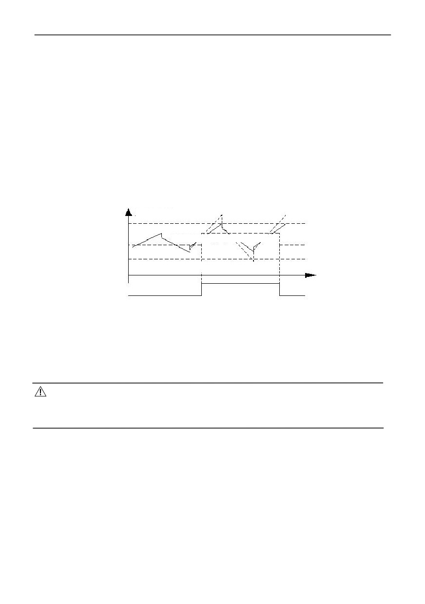
17: upper limit and lower limit of swing frequency
After selecting the swing frequency function, if the frequency fluctuation range of the swing frequency, calculated by
the center frequency, exceeds the upper limit frequency F00.13 and falls below the lower limit frequency 00.14 , there is
output an signal. As shown in the figure below:
Upper limit frequency
Center frequency of swing frequency
Lower limit frequency
Swing frequency exceeds the upper and lower limit
Figure F7-6 Schematic diagram of swing frequency amplitude limitation
18: Current limit in operation
It is the output signal when the inverter is in a current limit . Please refer to the description of function codes 10.06 ~
10.08 for current limit protection settings.
19: Overvoltage stall in operation
It is the signal output when the inverter is in overvoltage stall operation. Please refer to the description of function
code 10.04 for setting of overvoltage stall protection.
20: Undervoltage block and stop
When the DC bus voltage is lower than the undervoltage limit level, there is an indication signal.
Notes:
When the Bus is under-voltage during shutdown, digital tube displays “PoFF”; When the bus is under-voltage during
operation, if 10.02=0, the digital tube displays “PoFF”; if 10.02=1, the digital tube displays E-07 in fault, and the warning
indicator lights up at the same time.
21 Sleeping State
When the inverter is in the sleep state, the inverter will output indication signal.
22: Alarm signal of inverter
If there are the cases in the inverter of PID disconnection, RS485 communication failure, panel communication failure,
EEPROM reading and writing failure, encoder disconnection, etc., the inverter will output an indication signal.
23:AI1>AI2
When the analog input AI1>AI2, the inverter outputs the indication signal. Please refer to 06.05 ~ 06.11 parameter
description for details of analog input.
24: Output when length reach
When the actual length (09.69) is greater than or equal to the set length (09.68), an indication signal is output. The
length counting terminal DI6 is set to function No.47.
25: Timing time arrives
When the actual timing time is ≥ 07.36 (set timing time), the inverter will output the indication signal.
26: Dynamic braking action
When the inverter dynamic braking runs, it outputs indication signal. Please refer to the function code 12.00 ~ 12.03
for the setting of dynamic braking function.
27: DC brake action
92
When the inverter DC braking runs, it outputs indication signal. For DC brake setting, please refer to function codes 01.00 ~
01.12.
28: Flux braking action
When the inverter runs the flux braking, it outputs indication signal. For flux braking setting, please refer to function
codes 01221.
29: Torque in limit
When the control mode is torque control, an indication signal is output. For details of torque control, please refer to group
04.10 ~ 04.23 parameter description.
30: Over-torque indication
The inverter is set according to 04.22 ~ 04.24, and outputs corresponding indication signals.
31: Auxiliary motor 1
32: Auxiliary motor 2
Terminal function of auxiliary motor 1 and 2 cooperate with process PID function module, that will realize simple
constant pressure water-supply function in one drive to control three motor.
33: The accumulated running time has arrived
When the inverter running limit time (12.11) reached, it outputs indication signal.
34 ~ 49: multi-speed or simple PLC operation segment number indication
Items 34 ~ 49 of the output terminal function respectively correspond to the 0 ~ 15 segments of multi-speed or simple
PLC . When the corresponding segment number, which is set by the output terminal, has arrived, then the inverter outputs
an indication signal.
50:Inverter operation indication
When the inverter is in the forward or reverse running state, it outputs indication signal.
51: Temperature arrival indication
When the actual temperature (D-33 ~ D-34) is higher than the temperature detection limit (10.14), the inverter outputs
an indication signal.
52: indication of Inverter shutdown or zero speed running
53~54:Reservation
55: communication settings
Please refer to the communication protocol.
56:Inverter operation in ready 2
It has the same function as the above No.14 (Inverter operation in ready 1), except that when the inverter is running, it
outputs an indication signal.
57: AI1 input overrun
When the value of analog input AI1 is greater than 06.53(AI1 input voltage protection upper limit) or less than
06.54(AI1 input voltage protection lower limit), an indication signal is output.
58:output current is beyond the limit
59: Interlock 1 Output
60: Interlock 2 Output
61: Interlock 3 Output
62: Output when frequency and current detection level arrive at the same time
When the output frequency of the inverter rises higher than the set value of FDT1 level setting (07.25), and the output
current reaches the set value of 10.23, it outputs an valid signal (open collector signal, which will become low level after the
resistor is pulled up). While the output frequency drops below FDT1 signal (set value-hysteresis value), or the output
current is less than the set value of 10.23, it outputs an invalid signal (high impedance state).
Effective logic setting of output terminal (Y1~Y2)
07.22
0~3H
0
Bit0: valid logic definition of Y1 terminal
Bit1: valid logic definition of Y2 terminal
0: indicates positive logic, that is valid for connection between Yi terminal and common terminal, and is invalid for
disconnection.
1: means anti-logic, that is invalid for connection between Yi terminal and common terminal is invalid, and valid for
disconnection.
When 07.22=0, is valid for connection between terminals Y1, Y2
and the common terminal, while invalid for
disconnection.
When 07.22=1, is invalid for connection between Y1 terminal and common terminal, but the opposite is valid; while
invalid for connection between Y2 terminal and common terminal, but disconnection is valid
When 07.22=2, is valid for connection between Y1 terminal and common terminal, but the opposite is invalid; while
invalid for connection between Y2 terminal and common terminal, but disconnection is valid
When 07.22=3,is invalid for connection between terminals Y1, Y2
and the common terminal, while valid for
disconnection.
The frequency reaches the FAR detection width
07.23
0.0 ~ 100.0% * [00.12] maximum frequency
100.0%
This function is a supplementary explanation to the function No.6 of function code 07.18 ~ 07.21. When the output
frequency of the inverter is within the positive and negative detection width of the set frequency, the terminal outputs an
valid signal (open collector signal, which is low level after the resistance is pulled up). As shown in the figure below:
93
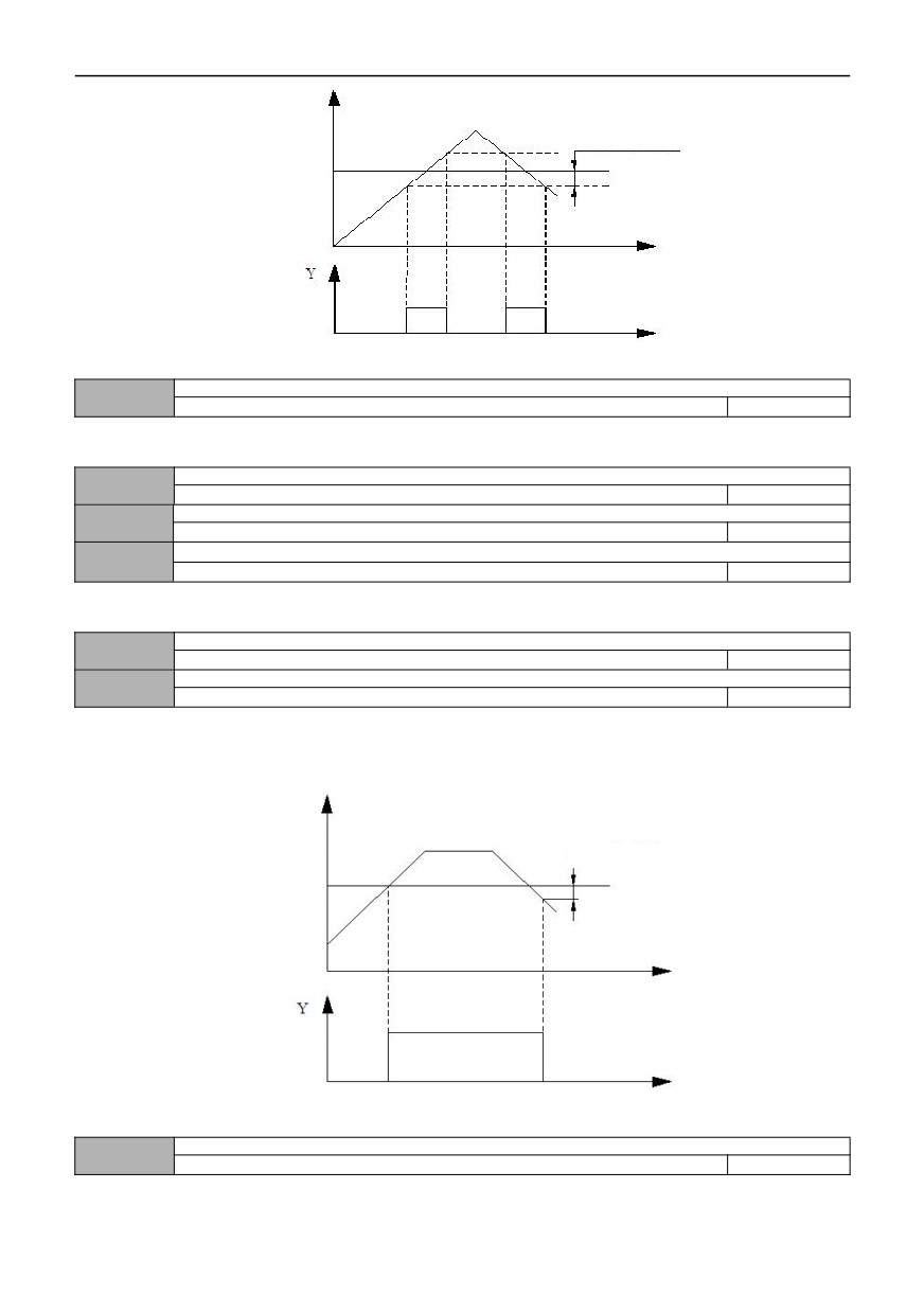
FAR detection amplitude
Set frequency
Time
Time
Figure F7-7 Schematic diagram of frequency arrive
FDT1 detection mode
07.24
0~1
0
0: speed setting value
1: speed detection value
FDT1 level setting
07.25
0.00Hz~【00.13】upper limit frequency
50.00
FDT1 hysteresis value
07.26
0.0~100.0%*【07.25】
2.0%
FDT2 detection mode
07.27
0~1
0
0: speed setting value
1: speed detection value
FDT2 level setting
07.28
0.00Hz~【00.13】upper limit frequency
25.00
FDT2 hysteresis value
07.29
0.0~100.0%*【07.28】
4.0%
The above function codes (07.24 ~ 07.29) are supplementary descriptions for functions No.4 and No.5 of function
codes 07.18 ~ 07.21. When the output frequency of the inverter rises above the set value of FDT level, it outputs an valid
signal (open collector signal, which is low level after the resistor is pulled up). When the output frequency drops below FDT
signal (set value-hysteresis value), it outputs an invalid signal. As shown in the figure below:
Set value of FDT
FDT hysteresis value
level
Time
Time
Figure F7-8 Schematic diagram of frequency level detection
Processing in the Count arrival
07.30
0~3
3
94
0: stop counting and output
1: stop counting and continue outputting
2:cycle the counting,and stop output
3: cycle counting, and continue to output
When the count value of the counter reaches the value, set by function code 07.32, the corresponding action of the inverter
is performed.
Starting condition of Counting
07.31
0~1
1
0: Always start when powered on
1: Start when running, will stop when stopping
The above premise is that there is a counting pulse input
Setting reset value of the counter
07.32
【07.33】~65535
0
Setting detection value of counter
07.33
0~【07.32】
0
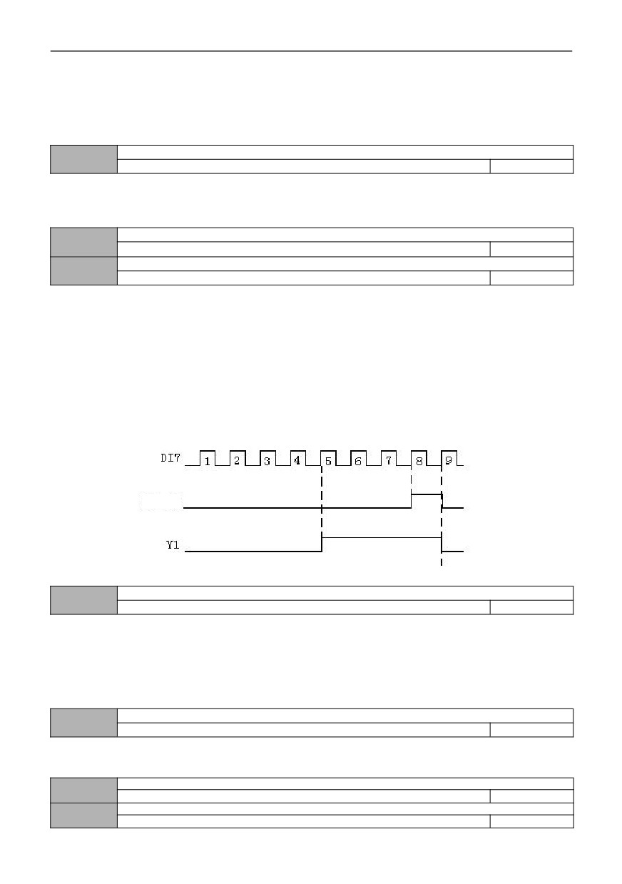
This function code defines the reset value and detection value of the counter. When the counting value of the counter
reaches the value, set by function code 07.32, the corresponding multi-function output terminal (counter reset signal output)
outputs an valid signal and clears the counter.
When the count value of the counter reaches the value, set by function code 07.33, an valid signal is output at the
corresponding multi-function output terminal (counter detection signal output). If counting continues and exceeds the value,
set by function code 07.32, the output valid signal will be cancelled when the counter is cleared.
As shown in the following figure, the programmable relay output is set as the reset signal output, and open collector
output Y1 set as counter detection output, 07.32 as 8 and 07.33 as 5. When the detection value is 5, Y1 keeps to output an
valid signal; When the reset value reaches 8, the relay outputs an valid signal of one pulse period and clears the counter. At
the same time, Y1, the relay cancel the output signal.
Relay
Figure F7-9 Schematic diagram for counter setting of reset and detection
Processing of Timing arrival
07.34
0~3
3
0: stop timing and output
1: stop timing and continue output
2:cycle timing, stop output
3: cycle counting, continue to output
When the count value of the counter reaches the value, set by function code 07.36, the corresponding action of the
inverter is performed.
Timing starting condition
07.35
0~1
1
0: Always start when powered on
1: Start when running,will stop when stopping
Setting of the timing time
07.36
0~65535S
0
Y1 delay time of disconnect
07.37
0.0~100.0s
0.0
95
Y2 delay time of disconnect
07.38
0.0~100.0s
0.0
R1 delay time of disconnect
07.39
0.0~100.0s
0.0
R2 delay time of disconnect
07.40
0.0~100.0s
0.0
008 group -PID control parameters
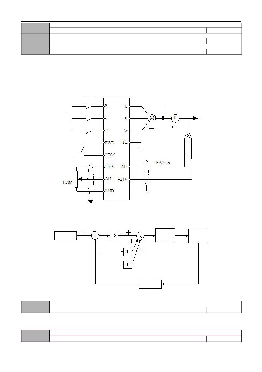
By setting this parameter group, a complete control system of analog feedback can be formed.
Control system of analog feedback: the setting value is input with AI1, and the physical value of the controlled object is
converted into 4 ~ 20mA current, which is input through AI2 of the inverter. The current goes through the built-in PI
regulator, so that forms an analog closed-loop control system, as shown in the below figure:
Breaker
Drive part
Power
supply
FWD/Stop
command
Sensor
Setting value
Figure F8-1 Schematic diagram of analog feedback control system
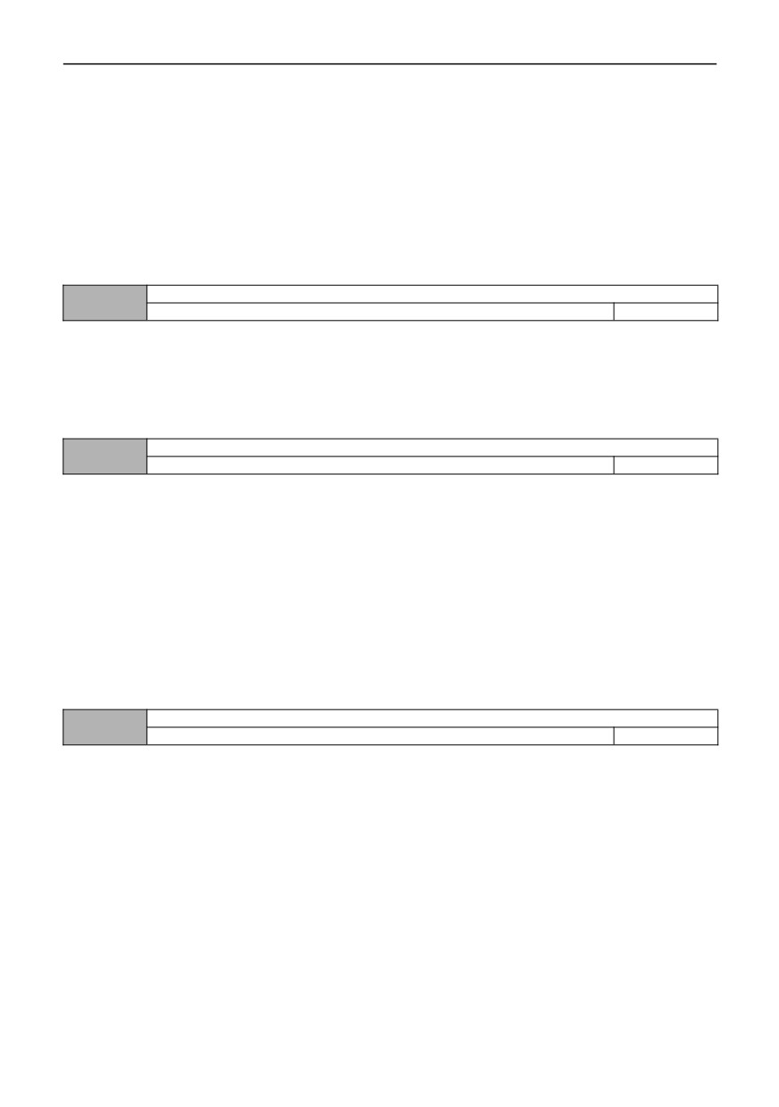
PID regulation functions are as follows:
Drive part
Controlled
Setting value
object
Feedback
quantity
Feedback
regulation
Fig. F8-2 PID regulation schematic diagram
PID operation mode
08.00
0~1
0
0: Automatic
1: manually input through the defined multi-function terminal
PID setting channel selection
08.01
0~6
0
96
0:Number setting
PID setting value is setting in using numbers,through the function code 08.02.
1:AI1
PID setting value is set by external analog signal AI1 (0 ~ 10V/0-20mA).
2:AI2
PID setting value is set by external analog signal AI2 (0 ~ 10V).
3: Pulse setting
PID setting value is given by external pulse signal.
4: RS485 communication
The PID setting value is set by the communication.
5: pressure setting value (MPa)
See 08.25~08.26 for detail
6: Panel potentiometer setting
Set of digital setting value
08.02
0.0~100.0%
50.0%
When using analog feedback, this function code can set the setting value of closed-loop control through using the
operation panel. But this function is valid only when the digital setting channel of closed-loop is selected (08.01 is 0).
For example, in the closed-loop control system of constant pressure water supply, the setting of this function code
should fully consider the counting relationship between the range of the remote pressure gauge and its output feedback
signal. For example, the range of the pressure gauge is 0 ~ 10 MPa, which corresponds to the output voltage of 0 ~ 10 V,
and we need 6 MPa pressure, so we can set the digital value into 6.00V, so when the PID regulation is stable, the required
pressure is 6 MPa.
Selection of PID feedback channel
08.03
0~7
0
0:AI1
The feedback value of PID is set by the external electric analog signal AI1.
1:AI2
The feedback value of PID is set by the external analog signal AI2.
2:AI1+ AI2
The feedback value of PID is determined by the sum of AI1 and AI2.
3:AI1-AI2
The feedback value of PID is determined by the difference between AI1 and AI2. When the difference is negative, the
feedback value of PID defaults to 0.
4:MAX{AI1,AI2}
5:MIN{AI1,AI2}
6: Pulse setting
7: RS485 communication
Advanced characteristic setting of PID controller
08.04
0000~101
000
LED bit: PID regulation characteristics
0: positive effect
When the feedback signal is higher than the set value of PID, the output frequency of the inverter is required to
decrease (means that the feedback signal is reduced), so that the PID can reach the balance. All that means a positive
characteristic. Such as using for tension control of winding machine and constant pressure water supply control.
1: negative effect
When the feedback signal is higher than the set value of PID, the output frequency of inverter is required to rise (that is,
the feedback signal is reduced), so that the PID can reach balance. All that means a negative characteristic. Such as
tension control of winding machine and central air conditioning control.
LED bit: Proportional-integral control characteristics (reservation)
0: constant proportional-integral control
1: automatic proportional-integral control
LED hundred-digit: integral control characteristic
0: stop integral adjustment when the frequency reaches the upper and lower limits
1: when the frequency reaches the upper and lower limits, continue the integral adjustment
For systems requiring rapid response, it is recommended to cancel the continuous integral adjustment
LED thousand bits: reservation
97
Proportional gain KP1
08.05
0.01~100.00s
2.50
Integral time Ti1
08.06
0.01~10.00s
0.10
Differential time Td1
08.07
0.01~10.00s
0.00
0.00: No derivative adjustment
Proportional gain (Kp):
The adjustment intensity of the whole PID regulator is determined by this. And the greater the P is, the greater the
adjustment intensity is. But if in too large state, there is easy to produce oscillation.
When the feedback deviates from the set value, the deviation and output become the regulating value of proportion. If
the deviation is constant, the regulating value is also constant. Proportional adjustment can quickly show out the feedback
changes, but it is impossible to achieve error-free control by proportional control alone. The larger the proportional gain is,
the faster the adjustment speed of the system will be, but if too large, oscillation will occur. The adjustment method is to set
the integration time for a longer time, and the differentiation time for zero, then use proportional control to make the system
run. With changing the size of the given quantity, it can observe the stable deviation (static difference) between the
feedback signal and the set value. If the static difference changes in the direction of the set value (for example, if the set
value is increased and the feedback value is always less than the set value after the system is stable), then increasing the
proportional gain continues. Otherwise reduce the proportional gain, and repeat the above process until the static
difference is relatively small (It's hard to make it without any static errors)
Integral time (ti):
Determine the speed of PID regulators to do the integral adjustment of deviation.
When the feedback deviates from the set value, the output adjustment value need to continuously accumulate. And if
the deviation persists, the adjustment value continuously increases until there is no deviation. Integral regulator can validly
eliminate static difference. If the integral regulator is too strong, there will be repeated overshoot, which will make the
system oscillate. Generally, the adjustment of integration time parameters is from large to small, and the integration time is
gradually adjusted, while the effect of system adjustment is observed,all until the stable speed of the system meets the
requirements.
Differential time (Td):
Determine the strength of PID regulator to adjust the rate of deviation change.
When the feedback changes with the set deviation, the rate of deviation change and output become the regulating value of
proportion, which is only related to the direction and magnitude of deviation change, but has nothing to do with the direction
and magnitude of deviation itself. when the feedback signal changes, the function of derivative adjustment is to adjust
according to the changing trend of it, so as to restrain the change of it. Please use derivative regulator with caution,
because derivative regulator is easy to amplify the interference of the system, especially the interference from large
changing frequency.
Sampling period T
08.08
0.01~100.00s
0.10
0.00: Automatic
Sampling period is the period to sample the feedback value, and the regulator operates once in each sampling period.
The larger the sampling period, the slower the response, but the better the suppression effect on interference signal, so it is
generally unnecessary to set it.
Deviation limit
08.09
0.0~100.0%
0.0%
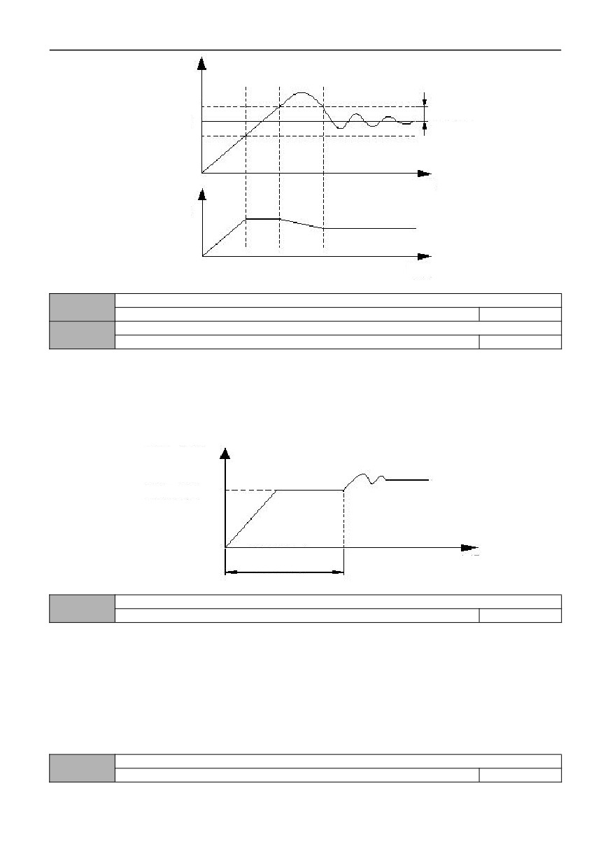
The deviation limit is the ratio of the set value and the absolute value,which means the absolute deviation value
between system feedback value and the set value. When the feedback value is within the deviation limit, PID control does
not work. As shown in the figure below, setting a reasonable deviation limit can prevent the system from frequently
adjusting near the target value, which is helpful to improve the stability of the system.
98
Feedback
quantity
Given
Deviation limit
quantity
Time
Output
frequency
Time
Figure F8-3 Schematic diagram of deviation limit
Closed loop preset frequency
08.10
0.00 ~ upper limit frequency
0.00
Preset frequency holding time
08.11
0.0~3600.0s
0.0
This function code defines the frequency and running time of inverter before PID is put into operation when PID control
is valid. In some control systems, in order to make the controlled object reach the preset value quickly, the inverter forcibly
outputs a certain frequency value of 08.10 and a frequency holding time of 08.11 according to the setting of this function
code. That is, when the control object is close to the control target, the PID controller is put into operation to improve the
response speed. As shown in the figure below:
Output frequency
Preset frequency
Preset frequency
Time
Holding time
Figure F8-4 Schematic diagram of closed-loop preset frequency operation
Sleep mode
08.12
0~2
1
0: Invalid
1: Sleep when feedback pressure exceeds or falls below sleep threshold
This mode is the first sleep mode of PID, as shown in Figure F8-5
2: Sleep when feedback pressure and output frequency are stable
This mode is the second sleep mode of PID. There are two situations (as shown in Figure F8-6):
1) if the feedback value is less than the given value and greater than the given value *(1-set deviation [08.14]), the
change of output frequency is within 6%, and then sleep after the sleep delay time [08.17].
2) If the feedback value rises above the given value, keep the sleep delay time [08.17] and then go to sleep. On the
contrary, if the feedback value drops below the awakening threshold [08.16], wake up immediately.
Selection of sleep shutdown mode
08.13
0~1
0
99