HV100 Series Frequency Inverter. User Manual (V4.0) - page 3
HV100
Series High Performance Current Vector Inverter
008group-PID Control Parameter
Function
Setting
Name
Content
Factory
Alteration
code
range
0: Automatic
PID operation
08.00
1: Manually operation through the defined multi-function
0~1
0
×
mode
terminal
0: Digital given
1: AI1
2: AI2
PID setting
08.01
3: Pulse given
0~6
0
○
channel selection
4: RS485 communication
5: Pressure given(MPa、Kg)
6: Potentiometer given
When using analog feedback, this function code realizes
setting the given quantity of closed-loop control with the
Set by digital
0.0~
08.02
keypad, and this function is effective only when the
50.0%
○
quantity
100.0%
digital given channel of closed-loop is selected (08.01 is
0).
0: AI1
1: AI2
2: AI1+AI2
PID feedback
3: AI1-AI2
08.03
0~7
0
○
channel selection
4: MAX{AI1,AI2}
5: MIN{AI1,AI2}
6: Pressure given
7: RS485 communication
LED single digit:PID polarity selection
0: Positive
1: Negative
LED10 digit: )Scaling characteristics
0: Constant proportional integral regulation
Advanced
1: Automatic proportional intergral regulation
characteristic
08.04
LED100 digit: Integral regulation characteristic
000~111
000
×
setting of PID
0: when the frequency reaches the upper and lower
controller
limit,stop the integral adjustments
1: when the frequency reaches the upper and lower
limit,continue the integral adjustments
LED1000 digit: Reserved
Proportional gain
0.01~
08.05
The speed of PID adjustment is set by two parameters:
2.50
○
KP1
100.00
proportional gain and integration time. For fast
adjustment, it is necessary to increase proportional gain
Integration time
0.01~
08.06
and reduce integration time; for slow adjustment, it is
0.10
○
Ti1
10.00s
necessary to reduce proportional gain and increase
integration time. Under normal circumstances, the
Differential time
0.01~
08.07
differential time is not set; 0.0: no differentiation.
0.00
○
Td1
10.00s
40
HV100
Series High Performance Current Vector Inverter
Sampling period is the sampling period of feedback, and
the regulator operates once in each sampling period.
The larger the sampling period, the slower the response,
0.01~
08.08
Sampling period T
0.10
○
but the better the suppression effect on interference
10.00s
signal, so it is generally unnecessary to set it; 0.00:
automatic.
The deviation limit is the ratio of the absolute value of the
deviation between the feedback amount and the given
0.0~
08.09
Deviation limit
0.0%
○
amount of the system. When the feedback amount is
100.0%
within the deviation limit, the PID adjustment will not act.
This function code defines the frequency and running
time of inverter before PID is put into operation when PID
0.00~Upper
Closed loop preset
08.10
control is effective. In some control systems, in order to
limit
0.00
○
frequency
frequency
make the controlled object reach the preset value
quickly, the inverter forcibly outputs a certain frequency
value of 08.10 and a frequency holding time of 08.11
according to the setting of this function code. That is,
Preset frequency
when the control object is close to the control target, the
0.0~
08.11
0.0
×
holding time
PID controller is put into operation to improve the
3600.0s
response speed.
0: Invalid
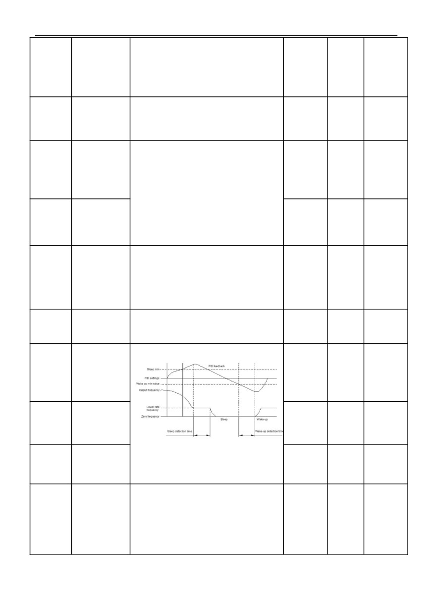
1: Sleep when the feedback pressure exceeds or falls
below the sleep threshold
08.12
Sleep mode
0~3
1
×
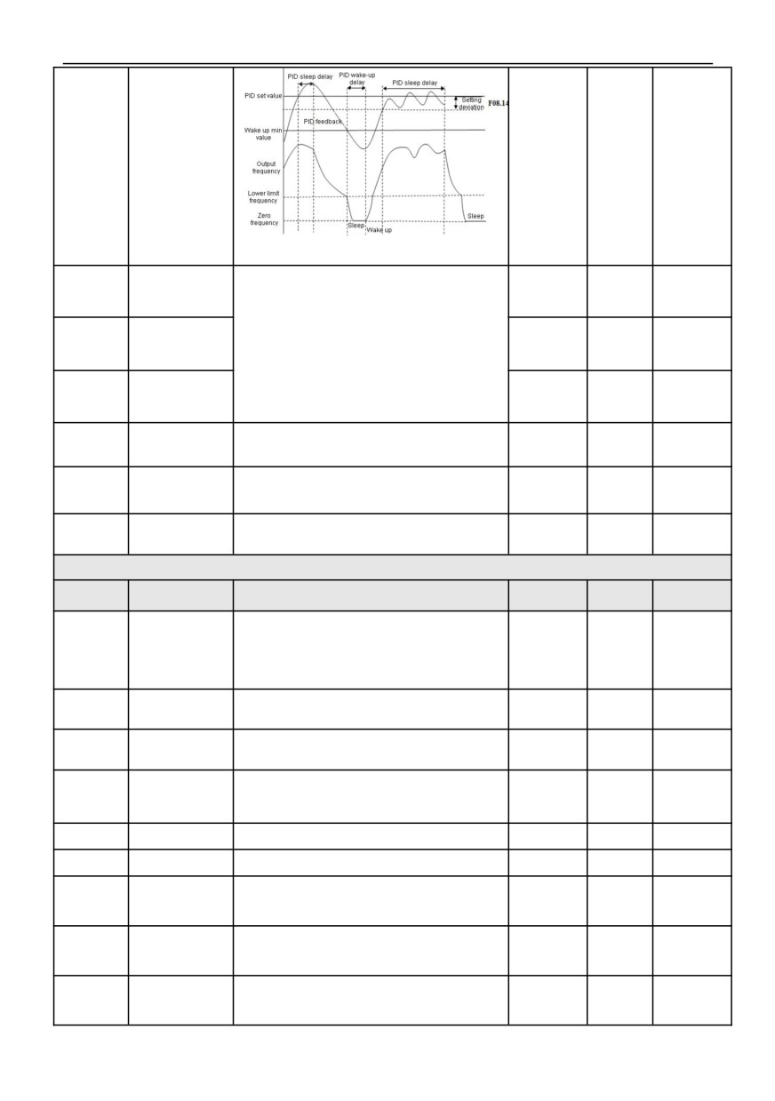
2: Sleep when feedback pressure and output frequency
are stable
3: Reserved
Selection of sleep
0: Deceleration stop
08.13
0~1
0
○
stop mode
1: Free stop
Deviation between
feedback and set
08.14
0.0~10.0%
0.5%
○
pressure when
entering sleep
0.0 ~
08.15
Sleep threshold
200.0% * set
100.0%
○
pressure
0.0 ~
08.16
Wake threshold
08.12=1 schematic diagram (sleep mode 1)
200.0% * set
90.0%
○
pressure
0.0~
08.17
Sleep delay time
100.0
○
3600.0s
41
0.0~
08.18
Wake delay time
5.0
○
3600.0s
08.12=2 schematic diagram (sleep mode 2)
Proportional gain
0.01~
08.19
1.00
○
KP2
The speed of PID adjustment is set by two parameters:
100.00
proportional gain and integration time. For fast
adjustment, it is necessary to increase proportional gain
Integration time
0.01~
08.20
and reduce integration time; for slow adjustment, it is
0.10
○
Ti2
10.00s
necessary to reduce proportional gain and increase
integration time. Under normal circumstances, the
Differential time
0.01~
08.21
differential time is not set; 0.0: no differentiation.
0.00
○
Td2
10.00s
Upper limit cut-off
frequency of PID
【08.23】~
08.22
Set PID upper limit cut-off frequency
50.00
×
300.00Hz
Lower limit cut-off
frequency of PID
—300.00Hz
08.23
Set PID lower limit cutoff frequency
0.00
×
~【08.22】
0.00Hz~
08.24
Sleep frequency
Set Sleep frequency
0.00
×
【00.13】
009Group-PLC、Multistage speed、Swing frequency and Fix length control
Function
Setting
Name
Content
Factory
Alteration
code
range
0: stop after single cycle
Selection of PLC
1: Keep the final value running after a single cycle
09.00
0~3
0
×
operation mode
2: Limited times continuous cycle
3: Continuous cycle
0: Automatic
Operation mode of
09.01
1: Manually operation through the defined multi-function
0~1
0
×
PLC
terminal
Memory of PLC
0: Not store
09.02
running power
1: Remember the stage and frequency of power-down
0~1
0
×
failure
time
0: Restart
1: Start from the stage of shutdown (failure) time
09.03
PLC starting mode
0~2
0
×
2: Start from the stage and frequency of shutdown
(failure) time
Finite number of
09.04
Set PLG Finite cycle number
1~65535
1
○
continuous cycles
Selection of PLC
09.05
0: s
1: min
0~1
0
×
running time unit
-Upper limit
Multistage speed
frequency~
09.06
Set Multistage speed frequency 0
5.00
○
frequency 0
Upper limit
frequency
-Upper limit
Multistage speed
frequency~
09.07
Set Multistage speed frequency 1
10.00
○
frequency 1
Upper limit
frequency
-Upper limit
Multistage speed
frequency~
09.08
Set Multistage speed frequency 2
15.00
○
frequency 2
Upper limit
frequency
42
HV100
Series High Performance Current Vector Inverter
-Upper limit
Multistage speed
frequency~
09.09
Set Multistage speed frequency 3
20.00
○
frequency 3
Upper limit
frequency
-Upper limit
Multistage speed
frequency~
09.10
Set Multistage speed frequency 4
25.00
○
frequency 4
Upper limit
frequency
-Upper limit
Multistage speed
frequency~
09.11
Set Multistage speed frequency 5
30.00
○
frequency 5
Upper limit
frequency
-Upper limit
Multistage speed
frequency~
09.12
Set Multistage speed frequency 6
40.00
○
frequency 6
Upper limit
frequency
-Upper limit
Multistage speed
frequency~
09.13
Set Multistage speed frequency 7
50.00
○
frequency 7
Upper limit
frequency
-Upper limit
Multistage speed
frequency~
09.14
Set Multistage speed frequency 8
0.00
○
frequency 8
Upper limit
frequency
-Upper limit
Multistage speed
frequency~
09.15
Set Multistage speed frequency 9
0.00
○
frequency 9
Upper limit
frequency
-Upper limit
Multistage speed
frequency~
09.16
Set Multistage speed frequency 10
0.00
○
frequency 10
Upper limit
frequency
-Upper limit
Multistage speed
frequency~
09.17
Set Multistage speed frequency 11
0.00
○
frequency 11
Upper limit
frequency
-Upper limit
Multistage speed
frequency~
09.18
Set Multistage speed frequency 12
0.00
○
frequency 12
Upper limit
frequency
-Upper limit
Multistage speed
frequency~
09.19
Set Multistage speed frequency 13
0.00
○
frequency 13
Upper limit
frequency
-Upper limit
Multistage speed
frequency~
09.20
Set Multistage speed frequency 14
0.00
○
frequency 14
Upper limit
frequency
-Upper limit
Multistage speed
frequency~
09.21
Set Multistage speed frequency 15
0.00
○
frequency 15
Upper limit
frequency
0th stage speed
Set the 0th stage speed acceleration and deceleration
09.22
acceleration and
0~3
0
○
time
deceleration time
0th stage speed
09.23
running time
Set the 0th stage speed running time
0.0~6553.5s
0.0
○
(min)
1st speed
09.24
acceleration and
Set the 1st stage speed acceleration and deceleration
0~3
0
○
deceleration time
time
1st speed running
0.0~6553.5s
09.25
time
Set the 1st stage speed running time
0.0
○
(min)
2nd speed
Set the 2nd stage speed acceleration and deceleration
09.26
acceleration and
0~3
0
○
time
deceleration time
2nd speed running
0.0~6553.5s
09.27
time
Set the 2nd stage speed running time
0.0
○
(min)
3rd speed
Set the 3rd stage speed acceleration and deceleration
09.28
acceleration and
0~3
0
○
time
deceleration time
3rd speed running
09.29
time
Set the 3rd stage speed running time
0.0~6553.5s
0.0
○
(min)
43
HV100
Series High Performance Current Vector Inverter
4th speed
09.30
acceleration and
Set the 4th stage speed acceleration and deceleration
0~3
0
○
deceleration time
time
4th speed running
time
0.0~6553.5s
09.31
Set the 4th stage speed running time
0.0
○
(min)
5th speed
Set the 5th stage speed acceleration and deceleration
09.32
acceleration and
0~3
0
○
time
deceleration time
5th speed running
time
0.0~6553.5s
09.33
Set the 5th stage speed running time
0.0
○
(min)
6th speed
Set the 6th stage speed acceleration and deceleration
09.34
acceleration and
0~3
0
○
time
deceleration time
6th speed running
time
0.0~6553.5s
09.35
Set the 6th stage speed running time
0.0
○
(min)
7th speed
Set the 7th stage speed acceleration and deceleration
09.36
acceleration and
0~3
0
○
time
deceleration time
7th speed running
0.0~6553.5s
09.37
Set the 7th stage speed running time
0.0
○
time
(min)
8th speed
Set the 8th stage speed acceleration and deceleration
09.38
acceleration and
0~3
0
○
time
deceleration time
8th speed running
0.0~6553.5s
09.39
Set the 8th stage speed running time
0.0
○
time
(min)
9th speed
Set the 9th stage speed acceleration and deceleration
09.40
acceleration and
0~3
0
○
time
deceleration time
9th speed running
0.0~6553.5s
09.41
Set the 9th stage speed running time
0.0
○
time
(min)
10th speed
Set the 10th stage speed acceleration and deceleration
09.42
acceleration and
0~3
0
○
time
deceleration time
10th speed
0.0~6553.5s
09.43
Set the 10th stage speed running time
0.0
○
running time
(min)
11th speed
Set the 11th stage speed acceleration and deceleration
09.44
acceleration and
0~3
0
○
time
deceleration time
11th speed
0.0~6553.5s
09.45
Set the 11th stage speed running time
0.0
○
running time
(min)
12th speed
Set the 12th stage speed acceleration and deceleration
09.46
acceleration and
0~3
0
○
time
deceleration time
12th speed
0.0~6553.5s
09.47
Set the 12th stage speed running time
0.0
○
running time
(min)
13th speed
Set the 13th stage speed acceleration and deceleration
09.48
acceleration and
0~3
0
○
time
deceleration time
13th speed
0.0~6553.5s
09.49
Set the 13th stage speed running time
0.0
○
running time
(min)
14th speed
Set the 14th stage speed acceleration and deceleration
09.50
acceleration and
0~3
0
○
time
deceleration time
14th speed
0.0~6553.5s
09.51
Set the 14th stage speed running time
0.0
○
running time
(min)
15th speed
Set the 15th stage speed acceleration and deceleration
09.52
acceleration and
0~3
0
○
time
deceleration time
15th speed
0.0~6553.5s
09.53
Set the 15th stage speed running time
0.0
○
running time
(min)
09.54
Reserved
—
—
0
◆
44
HV100
Series High Performance Current Vector Inverter
Swing frequency
0: Invalid
09.55
0~1
0
×
control
1: Effective
0: Automatic
Swing frequency
09.56
1: Manually operation through the defined multi-function
0~1
0
×
operation mode
terminal
Swing amplitude
0: Fixed swing
09.57
0~1
0
×
control
1:Variable swing
Swing frequency
0: Start according to the state memorized before
09.58
stop/starting mode
stopping
0~1
0
×
selection
1: Restart
Power-down
storage of
0: Store
09.59
0~1
0
×
frequency swing
1: Not store
state
The frequency at which the frequency converter operates
0.00Hz~
Swing preset
before it enters the swing operation mode or when it
09.60
Upper limit
10.00
○
frequency
leaves the swing operation mode and the time it runs at
frequency
this frequency point. If the function code 09.61≠0 (swing
frequency preset frequency waiting time) is set, the
inverter directly enters the swing frequency preset
Swing preset
frequency operation after starting, and enters the swing
0.0~
09.61
frequency waiting
0.0
×
time
frequency mode after the swing frequency preset
3600.0s
frequency waiting time.
The amplitude of Swing frequency is determined by
09.62, and the operating frequency of swing frequency is
0.0~
09.62
Swing amplitude
0.0%
○
restricted by the upper and lower frequencies. If it is set
100.0%
improperly, the Swing frequency will not work normally.
This function code refers to the amplitude of rapid
decline after the frequency reaches the upper limit
0.0~50.0%
frequency of the swing frequency, and of course it also
(Relative
09.63
Jump frequency
swing
0.0%
○
refers to the amplitude of rapid rise after the frequency
frequency
reaches the lower limit frequency of the swing frequency.
amplitude)
If it is set to 0.0%, there is no sudden jump frequency.
Swing frequency
This function code defines the running time from the
0.1~
09.64
5.0
○
rise time
lower limit frequency to the upper limit frequency and
3600.0s
Swing frequency
from the upper limit frequency to the lower limit
0.1~
09.65
5.0
○
falling time
frequency.
3600.0s
09.66
Reserved
—
—
0
◆
Fixed length
0: Invalid
09.67
0~1
0
×
control
1: Effective
This set of functions is used to realize the fixed-length
0.000~
09.68
Set length
shutdown function.
0.000
○
65.535(KM)
The frequency converter inputs counting pulses from the
terminal (HDI defined as function 47 ), and obtains the
0.000~
09.69
Actual length
calculated length according to the number of pulses per
0.000
○
65.535(KM)
revolution of the speed measuring shaft (09.73 ) and the
circumference of the shaft (09.72 ).
Length
0.100~
09.70
Calculation length = count pulse number ÷ Number of
1.000
○
magnification
30.000
pulses per revolution × Measure the circumference of
shaft.
The calculated length is corrected by length
Length correction
09.71
0.01~1.000
1.000
○
coefficient
magnification (09.70) and length correction coefficient
(09.71), and the actual length is obtained.
45
HV100
Series High Performance Current Vector Inverter
Measure the
Actual length = calculated length × Length magnification
0.10~
09.72
circumference of
÷ Length correction factor.
10.00
○
100.00CM
shaft
When the actual length (09.69) ≥ the set length (09.68),
the inverter will automatically issue a shutdown
Number of pulses
instruction to stop. The actual length (09.69) should be
09.73
per rotation of
1~65535
1024
○
shaft (HDI)
cleared or modified before running again < Set the length
(09.68), otherwise it will not start.
010 group-Protect Parameters
Function
Setting
Name
Content
Factory
Alteration
code
range
LED single digit: motor overload protect mode:
0: Forbid
1: Common motor(Electronic thermal relay mode,low
speed with compensation)
2: Variable frequency motor (Electronic thermal relay
mode,low speed without compensation)
3: User defined mode
Motor Overload
LED10 digit: inverter overload protect mode:
10.00
protection
0: Forbid
000~123
11
×
selection
1: Common mode
2: User defined mode
LED100 digit: inverter overload alarm :
0: Forbid
1: Effective
LED1000 digit: Reserved
Note: please refer to 10.29 ~ 10.32 for the description of
user defined overload protection.
Motor overload
20.0%~
10.01
protection
20.0%~120.0%
100.0%
×
120.0%
coefficient
Undervoltage
0: Forbid
10.02
protection action
0~1
0
×
selection
1: Allowed (undervoltage is regarded as fault)
220V: 180~
280V
Undervoltage
This function code specifies the allowable lower limit
200V
Type
10.03
×
protection level
voltage of DC bus when the inverter works normally.
380V: 330~
setting
480V
350V
220V: 350~
390V
Overvoltage limit
Overvoltage limit level defines the operating voltage
370V
Type
10.04
×
level
380V: 600~
setting
during overvoltage stall protection.
780V
660V
Voltage limit
In the process of deceleration, the larger this value is, the
Type
10.05
coefficient during
stronger the ability to suppress overvoltage is.
0~100
×
setting
deceleration
0: Overvoltage stall protection is invalid.
Current limit
80%~
Overcurrent limit level defines the operating current
Type
10.06
level(only VF
200%* INV
×
during overcurrent stall protection.
setting
mode is valid)
rated current
Selection of
current limit in
0: Limited by 10.06 current limit level
10.07
0~1
0
×
weak magnetic
1: Limited by the converted current limit level of 10.06
field
Current limiting
In the process of acceleration, the larger this value is, the
Type
10.08
coefficient during
stronger the ability of restraining overcurrent is. 0:
0~100
×
setting
acceleration
acceleration current limit is invalid.
Current limiting
0 ~ 100 is automatic frequency reduction, and the larger
10.09
coefficient during
the coefficient, the faster the frequency reduction rate;
0~5000
40
×
constant speed
101 ~ 5000 means manual frequency reduction, 101
46
means 0.01Hz /s, and so on, and 5000 means 50.00/s.
Drop load
The load drop detection time (10.10) defines that the
10.10
0.1S~60.0S
5.0
○
detection time
output current of the frequency converter is less than the
load drop detection level (10.11) for more than a certain
Drop load
time, and then the load drop signal is output; 0: the load
0~100%*
10.11
INV rated
0%
○
detection level
drop detection is invalid.
current
By setting the parameters 10.12 A-09 10.13 ,when the
20%~
Overload
Type
10.12
200%* INV
○
pre-alarm level
output current of the frequency converter is greater than
setting
rated current
the overload pre-alarm level amplitude (10.12 ), the
Overload
frequency converter outputs the pre-alarm signal after
10.13
pre-alarm delay
0.0~30.0s
10.0
○
delay (10.13 ), which is displayed on the keypad
time
Temperature
By setting function No.51 in function codes 07.18 ~
0.0℃~
10.14
detection
07.21, when the temperature reaches this setting, an
65.0℃
×
threshold
90.0℃
indication signal is output.
0: Prohibit
Selection of input
1: Input protection invalid, output protection valid
Type
10.15
and output phase
0~3
×
lose protection
2: Input protection valid, output protection invalid
setting
3: All valid
When the input phase lose protection is selected to be
Input phase loss
effective and the input phase lose fault occurs, the
10.16
protection delay
0.0~30.0s
1.0
○
time
inverter will protect E-12 after the time defined in 10.16,
and stop freely.
When the actual output current of the motor is greater
Output phase lose
protection
than the rated current * [10.17 ], if the output phase
0%~100%*
10.17
INV rated
25%
×
detection
failure protection is effective, after a delay time of 5S ,the
reference
current
inverter protection will act [E-13], and stop freely.
If the ratio of the maximum value to the minimum value in
Output current
the three-phase output current is greater than this
unbalance
10.18
coefficient, and the duration exceeds 10 seconds, the
0.01~50.00
10.00
×
detection
coefficient
inverter will report the output current imbalance fault
E-13.
10.19
Reserved
—
—
0
◆
0: No action
1: Alarm and maintain operation at the frequency of
Treatment of PID
disconnection time
10.20
feedback
0~3
0
×
disconnection
2: Protection action and free stop
3: Alarm and decelerate to zero speed according to the
set mode
The maximum value given by PID is taken as the upper
limit value of feedback disconnection detection value. In
Feedback
the feedback disconnection detection time, when the
0.0~
10.21
disconnection
feedback value of PID is continuously less than the
0.0%
○
detection value
100.0%
feedback disconnection detection value, the inverter will
make corresponding protection actions according to the
setting of 09.20.
Feedback
Feedback the duration after disconnection and before
0.0~
10.22
disconnection
10.0
○
detection time
protection action.
3600.0S
Setting of FDT1
10.23
current detection
See function No.62 in 07.18 ~ 07.21 for details
0.~200.0%
0
◆
level
47
HV100
Series High Performance Current Vector Inverter
Selection of
0: Protection action and free stop
RS485
10.24
1: Alarm and maintain the status to continue operation
0~2
1
×
communication
abnormal action
2: Alarm and stop according to the stop mode
If RS485 communication fails to receive the correct data
signal within the time interval defined by this function
RS485
code, it is considered that RS485 communication is
communication
10.25
abnormal, and the inverter will make corresponding
0.0~100.0s
0.0
○
timeout detection
time
actions according to the setting of 10.24. When this value
is set to 0.0, RS485 communication timeout detection is
not performed.
Keypad
0: Protection action and free stop
communication
10.26
1: Alarm and maintain the status to continue operation
0~2
1
×
abnormal action
selection
2: Alarm and stop according to the stop mode
If the keypad communication fails to receive the correct
Keypad
data signal within the time interval defined by this
communication
10.27
function code, it is considered that the keypad
0.0~100.0s
1.0
○
timeout check-out
time
communication is abnormal, and the inverter will make
corresponding actions according to the setting of 10.26.
EEFROM reading
0: Protection action and free stop
10.28
and writing error
0~1
0
×
action selection
1: Alarm and maintain the status to continue operation
Motor overload
0~200%*
10.29
protection
When the 10.00 bit is set to 3, the output current reaches
Motor rated
150%
×
threshold
the motor overload protection threshold (10.29), and then
current
Motor overload
delays the motor overload protection detection time
10.30
protection
0~60000S
100
○
(10.30) and reports the motor overload E-08.
detection time
Inverter overload
0~200%*
10.31
protection
When 10.00 bit is 2, the output current reaches the
INV rated
150%
×
threshold
overload protection threshold of inverter (10.31), and
current
then delays the overload protection detection time of
Inverter overload
10.32
protection
inverter (10.32), and then reports the overload of inverter
0~60000S
60
○
detection time
E-09.
OC and module
When the failure times of OC and module exceed this set
10.33
fault limit reset
0~9999
5
○
times
value, it needs to be powered on again before resetting.
0: LED units
Selection of
encoder frequency
1: LED tens
10.34
0~3
0
○
adjustment start
2: LED hundreds
bit
3: LED thousands
10.35
Reserved
—
—
0
◆
011Group-RS485 communication parameters
Function
Setting
Name
Content
Factory
Alteration
code
range
Protocol selection
0: MODBUS
11.00
0~1
0
×
1: User defined
11.01
Local address
0: Broadcast address
1~247: Slave station
0~247
1
×
Communication
baud rate setting
0: 2400BPS
1: 4800BPS
2: 9600BPS
11.02
0~5
3
×
3: 19200BPS
4: 38400BPS
5: 115200BPS
48
HV100
Series High Performance Current Vector Inverter
0: No check(N,8,1)for RTU
1: Parity check(E,8,1)for RTU
2: Odd parity check(0,8,1)for RTU
11.03
Date format
0~5
1
×
3: No check(N,8,2)for RTU
4: Parity check(E,8,2)for RTU
5: Odd parity check(0,8,2)for RTU
Local machine
response delay
This function code defines the intermediate time interval
time
between receiving the data frame of the inverter and
sending the response data frame to the upper computer.
If the response time is less than the system processing
11.04
time, the system processing time shall prevail. If the
0~200ms
5
×
delay is longer than the system processing time, the
system will delay waiting after processing the data, and
then send the data to the upper computer until the
response delay time is up.
Transmission
0: Write response
11.05
response
0~1
0
×
processing
1: Write not response
Proportional
This function code is used to set the coefficient of the
linkage coefficient
frequency command received through the RS485
interface when the inverter is used as a slave. The actual
operating frequency is equal to the value of this function
11.06
0.01~10.00
1.00
○
code multiplied by the frequency setting command value
received through the RS485 interface. In linked control,
this function code can set the ratio of the running
frequency of multiple inverters.
LED single digit: Communication mode selection
0: General mode
1: Reserved
2: Reserved
3: Reserved
Transmission
4: Reserved
11.07
00~24
00
×
mode selection
LED10 digit: Broadcast frequency source selection
0: host set frequency
1: Host frequency source A
2: Host frequency source B
LED100 digit: Reserved
LED1000 digit: Reserved
49
LED single digit: Display and selection of communication
bus voltage
0: Normal display
1: Magnify 10 times
2: Magnify 100 times
3: Shrink 10 times
4: Shrink 100 times
LED10 digit: Communication current display selection
0: Normal display
1: Magnify 10 times
2: Magnify 100 times
3: Shrink 10 times
Communication
11.08
4: Shrink 100 times
000~444
000
×
display selection
LED100 digit: Operation frequency display selection
0:Normal display
1: Magnify 10 times
2: Magnify 100 times
3: Shrink 10 times
4: Shrink 100 times
LED1000 digit: Reserved
012 Group-Advanced functions and performance parameters
Function
Setting
Name
Content
Factory
Alteration
code
range
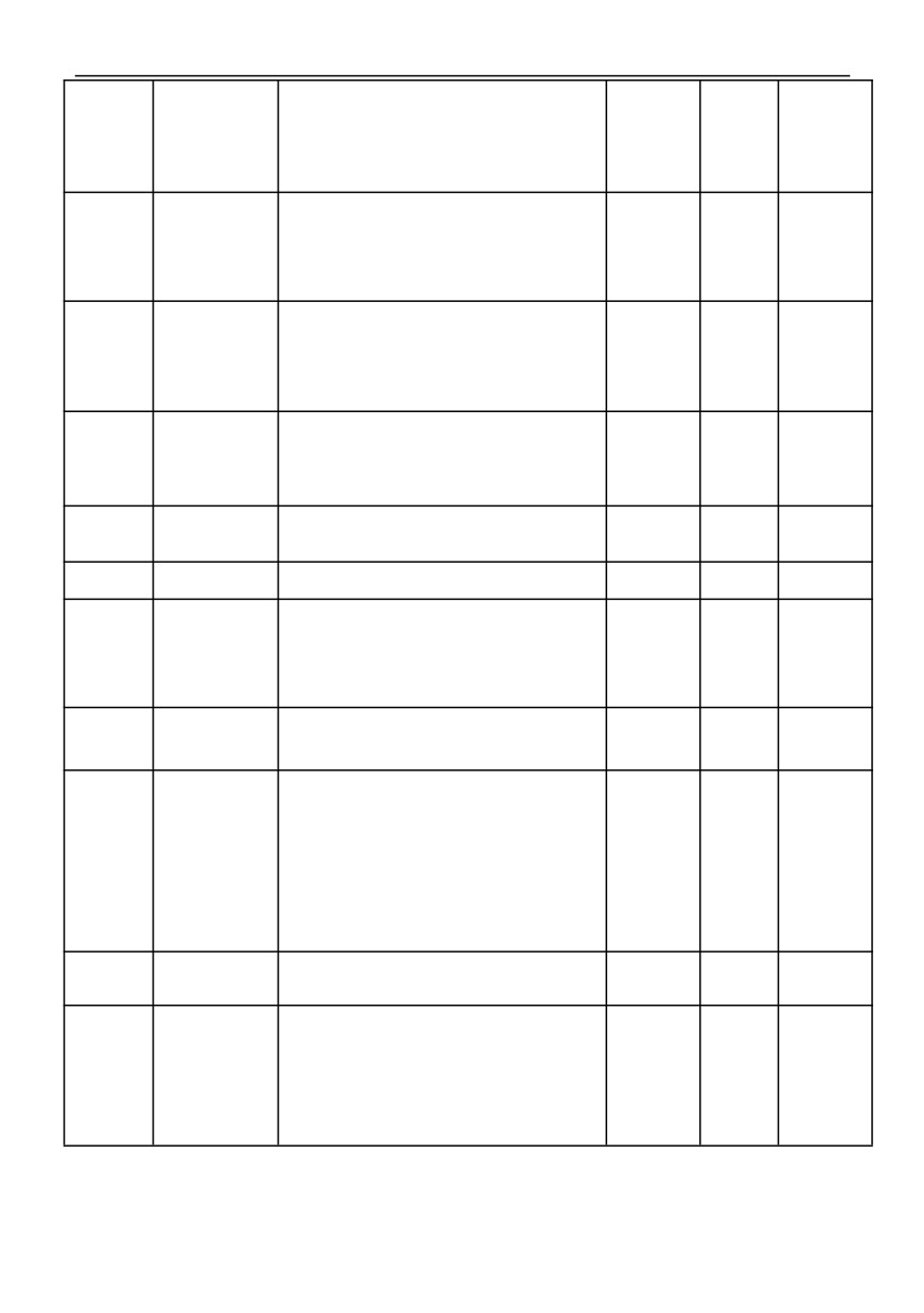
Energy
consumption
0: Invalid
12.00
braking function
1: Valid throughout
0~2
1
×
setting
2: Only valid when decelerating
220V:
Energy
340 ~ 380V
consumption
360V
Type
12.01
○
braking starting
380V:
setting
voltage
660 ~ 760V
680V
Energy
220V:
10 ~
consumption
100V
braking return
5V
Type
12.02
difference voltage
○
380V:
10 ~
setting
100V
10V
Energy
consumption
12.03
10~100%
100%
○
braking action
ratio
Power failure
restart settings
0: Forbid
12.04
1: Starting from starting frequency
0~2
0
×
2: Speed tracking start
Waiting time for
restart after power
During the waiting time for restart, any operation
failure
instruction entered is invalid. If the shutdown command
12.05
is input, the inverter will automatically release the speed
0.0~60.0s
5.0
×
tracking restart state and return to the normal shutdown
state.
50
HV100
Series High Performance Current Vector Inverter
Automatic
fault
reset times
The frequency of automatic fault reset is set by 12.06.
When the number of fault resets is set to 0, there is no
12.06
automatic reset function, and it can only be reset
0~100
0
×
manually. When 12.06 is set to 100, the number of times
is unlimited, that is, countless times.
Automatic
fault
reset interval
After a fault occurs during operation, the inverter stops
outputting and displays the fault code. After the reset
12.07
interval set in 12.07, the inverter automatically resets the
0.1~60.0s
3.0
×
fault and restarts the operation according to the set
starting mode.
Cooling fan control
0: automatic control mode
1: Always running during power-on
12.08
2. The fan will work when the temperature is higher than
0~2
0
○
50℃, and the fan will not work when the temperature is
lower than 45℃.
Password
for
running restricted
function
By default, the password is 0 ,and 12.10 and 12.11 can
12.09
be set; When there is a password, 12.10 and 12.11 can
0~65535
0
○
only be set after the password is verified correctly.
Selection
for
running restricted
0: Forbid
12.10
0~1
0
○
function
1:Effective
12.11
Run limit time
Set Run limit time
0~65535(h)
0
×
Frequency drop
point at
220V:180 ~
instantaneous
330V
If the inverter bus voltage drops below 12.12* rated bus
power failure
250V
Type
12.12
voltage, and the instantaneous stop control is effective,
×
380V:300 ~
setting
the instantaneous stop starts to act.
550V
450V
Frequency drop
coefficient
of
The larger the value is, the faster the frequency reduction
12.13
instantaneous
rate is.
0~100
0
○
power failure
0: the instantaneous stop function is invalid.
0.00: The droop control function is invalid
When multiple inverters drive the same load, the load
distribution is unbalanced due to different speeds, which
makes the inverters with higher speeds bear heavier
0.00
~
12.14
Dropping control
0.00
×
loads. The droop control characteristic is that the speed
10.00Hz
droops with the increase of load, which can make the
load evenly distributed; This parameter adjusts the
frequency variation of inverter with drooping speed.
Speed tracking
Before the inverter speed tracking starts, start tracking
12.15
0.1~5.0S
1.0
×
waiting time
after the delay.
Speed tracking
current
limiting
level
In the process of speed tracking, this function code plays
the role of automatic current limiting. When the actual
80
%
~
current reaches the threshold
(12.16), the inverter
12.16
200 % * INV
100%
×
reduces the frequency and limits the current, and then
continues to track and accelerate; The set value is a
Rtd current
percentage relative to the rated current of the inverter.
51
Speed tracking
When speed tracking restarts, select the speed of speed
speed
tracking. The smaller the parameter, the faster the
tracking speed. But too fast may lead to unreliable
12.17
tracking.
1~125
25
×
LED single digit: PWM synthesis mode
0: Full frequency seven segment
1: The seven paragraph turns to the five paragraph
LED10-digit: temperature correlation
0: Forbid
1:Effective
LED100-digit: Frequency correlation
0: All invalid
12.18
PWM mode
0000~1311
001
×
1: Low frequency adjustment,High frequency adjustment
2: Low frequency doesn't adjust,High frequency
adjustment
3: Low frequency adjustment,High frequency doesn't
adjust
LED1000-digit: Soft PWD function
0: invalid
1:Effective
Voltage
control
function
LED single digit: AVR function
0: Forbid
1: All Effective
2: Forbid only slow down
LED10 digit: Overmodulation selection
0: invalid
1:Effective
12.19
LED100 digit: Choice of death compensation
0000~3112
2112
×
0: Forbid
1:Effective
LED1000 digit: Shock suppression selection
0: invalid
1: Oscillation suppression mode 1
2: Oscillation suppression mode 2
3: Oscillation suppression mode 3
Oscillation
0.00
~
Type
12.20
suppression
Set oscillation suppression start frequency
○
300.00Hz
setting
starting frequency
Magnetic flux
braking selection
This parameter is used to adjust the magnetic flux
braking ability of the inverter during deceleration. The
larger this value is, the stronger the magnetic flux braking
ability is. To a certain extent, the shorter the deceleration
time, the parameter generally does not need to be set.
12.21
0~100
0
○
When this value is 0, this function is invalid.
When the overvoltage limit level is set low, turning on this
function can shorten the deceleration time appropriately.
When the overvoltage limit level is set high, it is not
necessary to turn on this function.
Energy
saving
control coefficient
0: Invalid
1: Automatic
12.22
0~100
0
○
Note: Energy-saving operation is only effective for
ordinary V/F control
Multi-speed
0: Forbid
12.23
priority enable
0~1
0
×
1: Multi segment speed takes precedence over 00.07
JOG
priority
0: Invalid
12.24
enable
0~1
0
×
1: JOG has the highest priority
52
HV100
Series High Performance Current Vector Inverter
Special function
LED single digit: AO2 and DO selection
0: AO2 Effective
1: DO Effective
LED10 digit: IPM Fault setting
0: Shield the fault
12.25
000~110
010
×
1: the fault is Effective
LED100 digit: input phase failure rest selection
0: Unable to reset
1: it can be reset after the power supply is normal
LED1000 digit: Reserved
Upper
limit
Set Upper limit frequency of oscillation suppression
frequency
of
0.00~
12.26
50.00
○
300.00Hz
oscillation
suppression
Oscillation
When 12.19 kilobits =1 (oscillation suppression mode
suppression
1), the PWM mode is forced to be five-segment; When
12.27
1~500
50
○
12.19 kilobits =2 (oscillation suppression mode 2), the
coefficient
original mode remains unchanged, and these two modes
can be adjusted by oscillation suppression coefficient
Oscillation
(12.27). In special occasions, if the first two modes cant
suppression
suppress the oscillation, use the oscillation suppression
voltage
mode 3 (12.19 thousands of bits =3 ), and adjust it
0.0~25.0%*
12.28
5.0
○
Rtd volt
together with the parameters 12.27 (oscillation
suppression coefficient) and 12.28 (oscillation
suppression voltage).
Wave-by-wave
current limiting
LED single digit: Selection of wave by wave current
and
limiting acceleration
anti-overvoltage
0: Forbid
action options
1:Effective
LED10 digit: Selection in wave by wave current limiting
deceleration
0: Forbid
12.29
1:Effective
0000~1111
011
○
LED100 digit: Selection of wave by wave current limiting
and constant speed
0: Forbid
1:Effective
LED1000 digit: Anti-overvoltage action selection
0: Forbid
1:Effective
Special function
LED single digit: Direct-Start function select
selection
0: Forbid
1: Effective
LED 10 digit: display selection of over-torque alarm A-05
Type
12.30
00~11
○
0: Forbid
setting
1: Effective
LED100 digit: Reserved
LED1000 digit: Reserved
013 Group-Reserved
014 Group Keypad function setting and parameter management
Function
Setting
Name
Content
Factory
Alteration
code
range
M-FUNC function
selection
0: JOG(Point control)
1: Forward/Reverse switch
14.00
2: Clear”▲/▼ “frequency setting
0~4
0
×
3: Local/Remote operation switch(Reserved)
4: Reverse direction
STOP/RST key
0: Only valid for keypad control
function Selection
1: Effective for both keypad and terminal control
14.01
0~3
3
○
2: Effective for keypad and communication control
3: Valid for all control modes
53
HV100
Series High Performance Current Vector Inverter
STOP+RUN key
0: Forbid
14.02
emergency stop
0~1
1
○
1: Free stop
function
Closed
loop
This function code is used to correct the display error
display coefficient
between the actual physical quantity
(pressure, flow,
0.01
~
14.03
etc.) and the given or feedback quantity
(voltage,
1.00
○
100.00
current) during closed-loop control, and has no influence
on closed-loop adjustment.
Load
speed
This function code is used to correct the display error of
0.01
~
14.04
display coefficient
1.00
○
speed scale, and has no influence on the actual speed.
100.00
Line
speed
This function code is used to correct the display error of
0.01
~
14.05
coefficient
linear speed scale, and has no influence on the actual
1.00
○
100.00
speed.
Encoder
14.06
The larger the value, the faster the encoder adjusts
1~100
70
○
adjustment rate
Monitoring
parameter
14.07
selection 1 in
The monitoring items of the main monitoring interface
0~57
0
○
running state
can be changed by changing the set values of the above
(main display)
function codes. For example, if
14.07=5, that is, the
Monitoring
output current d-05 is selected, the default display item of
parameter
the main monitoring interface is the current output
14.08
selection 2 in
current value during operation.
0~57
5
○
running state
(Auxiliary display)
Monitoring
parameter
14.09
selection 1 in stop
0~57
1
○
The monitoring items of the main monitoring interface
state (main
can be changed by changing the set values of the above
display)
function codes. For example, if
14.09=6, that is, the
Monitoring
output voltage d-06 is selected, the default display item
parameter
of the main monitoring interface will be the current output
14.10
selection 2 in stop
voltage value when the machine stops.
0~57
13
○
state (Auxiliary
display)
Parameter display
mode selection
LED ones: function parameter display mode selection
0: display all function parameters
1: only display the parameters that are different from the
factory value
2: only display the parameters modified after the last
power-on (reserved)
LED ten digits: monitor parameter display mode
selection
14.11
0000~1112
0100
○
0: only display main monitor parameters
1: Main and auxiliary display alternately (interval time 1s)
LED hundreds: adjust frequency display selection
0: display frequency
1: Only display status monitoring parameters
Thousands of LED: Panel ▲/▼ key adjustment enable
0: Valid
1: invalid
Parameter
initialization
0: No operation
1: All parameters except motor parameters are restored
14.12
to factory settings
0~3
0
×
2: Restore all user parameters to factory settings
3: Clear fault record
0: Modify all Parameter (Some parameters cannot be
modified during operation)
1: only the frequency settings 00.07 and 00.10 and this
function code can be modified
14.13
Parameter protect
0~2
0
○
2: All parameters except this function code are forbidden
to be modified
Note: the above restrictions are invalid for this function
code and 14.13
54
HV100
Series High Performance Current Vector Inverter
0: No operation
1: Upload parameters to the keypad
2: Download all function code parameters to the inverter
3: Download all function code parameters except motor
parameters to the inverter
Note 1: When selecting parameter download, the
14.14
Parameter copy
0~3
0
×
software will judge whether the inverter power
specifications are consistent. If they are inconsistent, the
parameters related to the model will not be modified.
Note 2: Only the external keyboard KB2 has the copy
function, and the normal keyboard copy will prompt an
error.
14.15
Software version
1.00~99.99
4.12
◆
14.15~14.16 View only, cannot be modified.
14.16
Keypad version
1.00~99.99
1.00
◆
0.4
~
This parameter can only be viewed and cannot be
Type
14.17
INV rated power
999.9KW
◆
modified.
setting
(G/P)
0: G type (constant torque load model)
1: P type (load type of fan and water pump)
Note 1: After setting as P type machine, the motor
Inverter
type
parameters will be refreshed automatically, and it can be
14.18
0~1
0
×
selection
used as a higher gear special frequency converter for fan
and water pump without changing any parameters.
Note 2: This parameter cannot be initialized, please
modify it manually
015 Group-Multiple pumps water supply parameters
Function
Setting
Name
Content
Factory
Alteration
code
range
Terminal
delay
15.00
The delay time when the pump is switched on and off.
0.0~600.0s
0.1
○
time
Polling time is the time to switch the variable frequency
15.01
Polling time
pump regularly, which is only valid when a single pump
0.0~600.0h
48.0
○
works.
Lower limit
When the feedback pressure is higher than the set
frequency for
pressure and the frequency drops to the lower limit
0.0
~
15.02
35.00
×
reducing the
frequency of pump reduction, the pump is reduced after
600.00HZ
number of pumps
the delay time of pump reduction.
This parameter is used in the "one drive three constant
Main pump
0.0
~
15.03
pressure water supply", the main pump start delay time
0.0
○
Start-up delay time
3600.0s
after the main and auxiliary pumps are switched.
Auxiliary pump
0: Direct start
15.04
0~1
0
×
Start-up mode
1: Soft start
Add pump delay
0.0
~
15.05
The delay time used for adding the pump,
10.0
○
time
3600.0s
Reduce
pump
0.0
~
15.06
The delay time used for reduce the pump,
10.0
○
delay time
3600.0s
0.00 ~ 60.00
15.07
Sensor range
10.00
○
(MPa、Kg)
If 08.01=5, select the sensor range (15.07) and the given
pressure (15.08) according to the field conditions.
0.00
~
15.08
Pressure setting
【 15.07 】
5.00
○
(MPa、Kg)
016 Group-Photovoltaic water pump MPPT parameters
55
Function
Setting
Name
Content
Factory
Alteration
code
range
Lack of water
16.00
0~250s
10
○
detect time
0
~ MPPT
MPPT low point
If the bus voltage (d-12) is higher than the set value of
High
16.01
350/200V
○
operating Voltage
MPPT high working voltage (16.02), it will run at the
operating
maximum frequency; if it is lower than the set value of
voltage
MPPT high working voltage (16.01), it will be operated
【16.01】~
MPPT high point
according to
(bus voltage/MPPT high point operating
1000 /
16.02
537/311V
○
operating Voltage
voltage)
* Maximum frequency operation. If the bus
【16.01】~
voltage reaches the MPPT low point operating voltage
500
Photovoltaic pump
(16.01), it will run at the lowest water output frequency
(16.04). If the inverter runs above the lowest water
80.0
~
water
shortage
frequency and the output current is less than Motor
300.0%*
detection current
16.03
no-load current
* Photovoltaic water pump water
High
150.0
○
corresponds to the
shortage detection current corresponds to the ratio of
operating
ratio of no-load
no-load current
(16.03). After the photovoltaic water
voltage
current
pump water shortage detection time (16.00), the inverter
Minimum
reports water shortage fault E-32.
operating
0.00Hz
~
16.04
frequency of
Upper limit
20.00
○
photovoltaic water
frequency
pump
d-xx Group-Monitoring parameter group and fault record
Function
Alteratio
Name
Setting range
Factory
code
n
d-00
Output frequency
0.00~Max output frequency【00.13】
0
◆
d-01
Settings frequency
0.00~Max output frequency【00.13】
0
◆
0.00~Max output frequenc【00.13】Note: the running
d-02
Motor estimated frequency
frequency of the motor is calculated from the
0
◆
estimated speed of the motor
d-03
Main frequency
0.00~Max output frequency【00.13】
0
◆
d-04
Auxiliary frequency
0.00~Max output frequency【00.13】
0
◆
d-05
Output current
0.0~6553.5A
0
◆
d-06
Output voltage
0~999V
0
◆
d-07
Output Torque
-200.0~+200.0%
0
◆
d-08
Motor rotation speed(rpm)
0~36000(rpm)
0
◆
d-09
Motor power factor
0.00~1.00
0
◆
d-10
Running line speed(m/s)
0.01~655.35(m/s)
0
◆
d-11
Setting line speed(m/s)
0.01~655.35(m/s)
0
◆
d-12
DC bus voltage(V)
0~999V
0
◆
d-13
Input voltage(V)
0~999V
0
◆
d-14
PID setting value(V)
0.00~10.00V
0
◆
d-15
PID feedback value(V)
0.00~10.00V
0
◆
d-16
Analog input AI1(V/mA)
0.00~10.00V
0
◆
d-17
Analog input AI2(V)
0.00~10.00V
0
◆
d-18
Pulse frequency input (KHz)
0.00~50.00kHz
0
◆
d-19
Analog output AO1(V/mA)
0.00~10.00V
0
◆
d-20
Analog output AO2(V)
0.00~10.00V
0
◆
0 ~ 7fh Note: After expanding to binary, it
means
d-21
Input terminal status
0
◆
HDI/DI6/DI5/DI4/DI3/DI2/DI1 from high to low
0 ~ FH Note: After expanding to binary, it
means
d-22
Output terminal status
0
◆
R2/R1/Y2/Y1 from high to low
0~FFFFH
BIT0: Start/Stop
BIT1: Forward/Reverse
BIT2: Zero speed operation
BIT3: Reserved
Operation
status
of
frequency
BIT4: Acceleration
d-23
0
◆
converter
BIT5: Deceleration
BIT6: Constant speed
BIT7: Pre-excitation
BIT8: Motor parameter tuning
BIT9: Over current limiting
BIT10: Over voltage limiting
56
BIT11: Torque limiting
BIT12: Speed limiting
BIT13: Speed control
BIT14: Torque control
BIT15: Reserved
Multi segment speed mode,current
d-24
0~15
0
◆
segment number
d-25
Pulse frequency output(Hz)
0~50000Hz
0
◆
d-26
Reserved
—
0
◆
d-27
Current count
0~65535
0
◆
d-28
Set count value
0~65535
0
◆
d-29
Current timing value(S)
0~65535S
0
◆
d-30
Setting timing value(S)
0~65535S
0
◆
d-31
Current length
0.000~65.535(KM)
0
◆
d-32
Setting length
0.000~65.535(KM)
0
◆
d-33
Radiator temperature1
0.0℃~+110.0℃
0
◆
d-34
Radiator temperature2
0.0℃~+110.0℃
0
◆
Accumulated running time of the
d-35
0~65535H
0
◆
machine(h)
Accumulated power-on time of the
d-36
0~65535H
0
◆
machine(h)
Accumulated running time of the
d-37
0~65535H
0
◆
FAN(h)
Accumulated electricity consumption
d-38
0~9999KWH
0
◆
(Low position)
Accumulated electricity consumption
d-39
0~9999KWH(*10000)
0
◆
(High position)
d-40
PID Pressure feedback
0.00~60.00(MPa、Kg)
0.00
◆
d-41
Output frequency
0.0~6553.5KW
0.0
◆
d-42
PID Pressure setting
0.00~60.00(MPa、Kg)
0.00
◆
d-48
4th fault type from last
0~34
0
◆
d-49
3rd fault type from last
0~34
0
◆
d-50
2nd fault type from last
0~34
0
◆
d-51
Latest fault type
0~34
0
◆
d-52
Operating frequency at latest fault
0.00~【00.13】Upper limit frequency
0
◆
d-53
Output current at latest fault
0.0~6553.5A
0
◆
d-54
DC bus voltage at latest fault
0~999V
0
◆
0~7FH
d-55
DI status at latest fault
Note: after expanding to binary,
it
means
0
◆
HDI/DI6/DI5/DI4/DI3/DI2/DI1 from high to low
0~FH
d-56
DO status at latest fault
Note: After expanding to binary, it
means
0
◆
R2/R1/Y2/Y1 from high to low
d-57
Inverter status at latest fault
0~FFFFH
0
◆
57
Chapter VII Description of Function Parameters
000 group-basic operating parameters
LCD language (only valid for LCD keypad)
00.00
0~2
0
0: Chinese
1: English
2:Reservation
Functional macro definition
00.01
0~20
0
0:General model
1: Single pump constant pressure water supply mode
2: One inverter with two working (1 variable frequency pump +2 power frequency pumps) water supply mode
3: Three-pump cycle soft start (3 variable frequency pumps) water supply mode
4: Photovoltaic pump water supply mode
5: CNC machine tool control mode
6: Fire patrol mode
7: EPS power mode
8~20:Reservation
Note: Initialize parameters first, and then set macro functions. Options 2 and 3 are detailed in the description of water
supply parameters.
Control mode
00.02
0~4
Model setting
0: Common V/F control
When more than one motor needs to be driven by a single inverter, and when the motor parameter self-learning cannot
be carried out correctly or the parameters of the controlled motor cannot be obtained by other means, the control mode is
selected. This control mode is the most commonly used motor control mode, which can be used in any occasion with low
requirements on motor control performance.
1: Advanced V/F control
This control mode introduces the idea of flux closed-loop control, which can greatly improve the torque response of
motor control in the whole frequency band and enhance the torque output ability of motor at low frequency, and at the same
time, it is not too sensitive to motor parameters like field-oriented vector control. This control mode is especially suitable for
some occasions with certain requirements on starting torque (such as wire drawing machine, ball mill, etc.)
2. SVC mode(SVC)-Open-loop current vector control (motor parameter sensitive mode)
The real current vector control mode has not only the high torque output performance of magnetic flux control mode,
but also the flexible torque output effect, which can be described as a combination of rigidity and flexibility. However, this
control mode is sensitive to motor parameters, so it is best to enable dynamic self-learning of motor parameters before
using it, otherwise the effect is not good.
3:Reserved
4. Separate V/F control
In this control mode, the output voltage and frequency of the inverter can be controlled independently, instead of
simply satisfying the constant V/F relationship, it can generally be used in the fields of variable frequency power supply,
EPS and so on.
Note: The factory default is 1 for below 55KW and 0 for above 75KW.
Run command channel selection
00.03
0~2
0
This function code selects the physical channel where the inverter accepts operation commands such as running and
stopping.
0: The operation panel runs the command channel
Operation control is implemented by the, RUN
,STOP/RESET
M-FUNC
and other keys on the operation panel.
1: Terminal operation command channel
58
Operation control is implemented by multi-function terminals defined as FWD, REV, JOG forward rotation, JOG
reverse rotation and other functions.
2: Communication operation command channel
Operation control is implemented by the upper controller through communication.
Notes:
Even in the running process, by modifying the set value of the function code, the running command channel can be
changed. Please set it carefully!
Selection of main frequency source A
00.04
0~11
9
0: Digital setting 1 (press keyboard key
, encoder+00.10)
The
initial value of frequency setting is 00.09, which can be adjusted by using operation panel key or digital
encoder. The modified frequency value will be stored in 00.09 after power failure (if you want this frequency not to be stored,
you can set 00.07 to 1.
1: Digital setting 2(UP/DOWN terminal +00.10)
The initial value of frequency setting is 00.10, and the operating frequency is changed by the on-off of multifunctional
terminals externally defined as UP/DOWN function (see 07 Group X terminal frequency increasing and decreasing item
function number for details). When the UP terminal and COM terminal are closed, the frequency rises; When the DOWN
terminal and COM terminal are closed, the frequency drops; The frequency remains unchanged when the UP/DOWN
terminal is closed or disconnected from the COM terminal at the same time. If frequency power-down storage is set, the
modified frequency value will be stored in 00.10 after power-down. The rate at which the UP/DOWN terminal modifies the
operating frequency can be set by function code 07.12.
Tips:
Whether
it is panel key adjustment or terminal UP/DOWN adjustment, the set value is superimposed with an
adjustment amount on the basis of 00.09 or 00.10, and the final frequency output value is from the lower limit frequency to
the maximum output frequency. The adjustment amount of terminal UP/DOWN adjustment can be cleared by selecting 0
for the UP/DOWN terminal frequency through X terminal. TheM-FUNC adjustment
amount of the panel can
also be cleared by selecting the clear key frequency setting.
2: Digital setting 3 (communication setting)
Change the set frequency through the serial port frequency setting command. See Group 011 communication
parameters for details.
3: AI1 analog setting (0 ~ 10V/20mA)
The frequency setting is determined by the analog voltage/current of AI1 terminal, and the input range is:
See the definition of function 06.00 ~ 06.05 for the related setting of DC 0 ~ 10V/20mA.
4: AI2 analog setting (0 ~ 10V)
The frequency setting is determined by the analog voltage/current of AI1 terminal, and the input range is:
See definition of function code 06.06 ~ 06.11 for related setting of DC 0 ~ 10 V.
5: Pulse setting(0~50Hz)
The frequency setting is determined by the terminal pulse frequency (it can only be input by DI6, see 07.05 definition),
and the input pulse signal specification: the high level range is 15 ~ 30V; The frequency range is 0 ~ 50khz. See the
definition of function code 06.15 ~ 06.20 for related settings.
6: Simple PLC
To select the given frequency mode of simple PLC, it is necessary to set the function code 09.00 ~ 09.05; Function
codes 09.06 ~ 09.21 are used to determine the operating frequency of each stage of PLC, and function codes 09.22 ~
09.53 respectively define the acceleration and deceleration time and operation time of each stage of PLC.
7:Multi- speed settings
Choose this frequency setting mode, and the inverter runs in multi-speed mode. It is necessary to set F7 group “X
terminal as multi-speed selection”and
009
groups of
“multi-speed frequency” function codes to determine the
corresponding relationship between a given number of multi-speed segments and a given frequency.
8: PID control
If this frequency setting mode is selected, the operation mode of inverter is process PID control. At this time, 008 sets
of process PID parameters and analog given and pulse given related function codes need to be set. Operating frequency of
inverter is the frequency value after PID action. Please refer to the detailed description of 008 group functions for specific
settings.
9: Keyboard potentiometer setting
The operating frequency is adjusted by operating the potentiometer on the keyboard, and the adjusting frequency
range of the potentiometer is fixed from 0 to the maximum output frequency [00.12].
10: MPPT given(Solar water pump)
11: Potentiometer
59