HV100 Series Frequency Inverter. User Manual (V4.0) - page 2
Chapter V Operation and display
5.1 keypad description
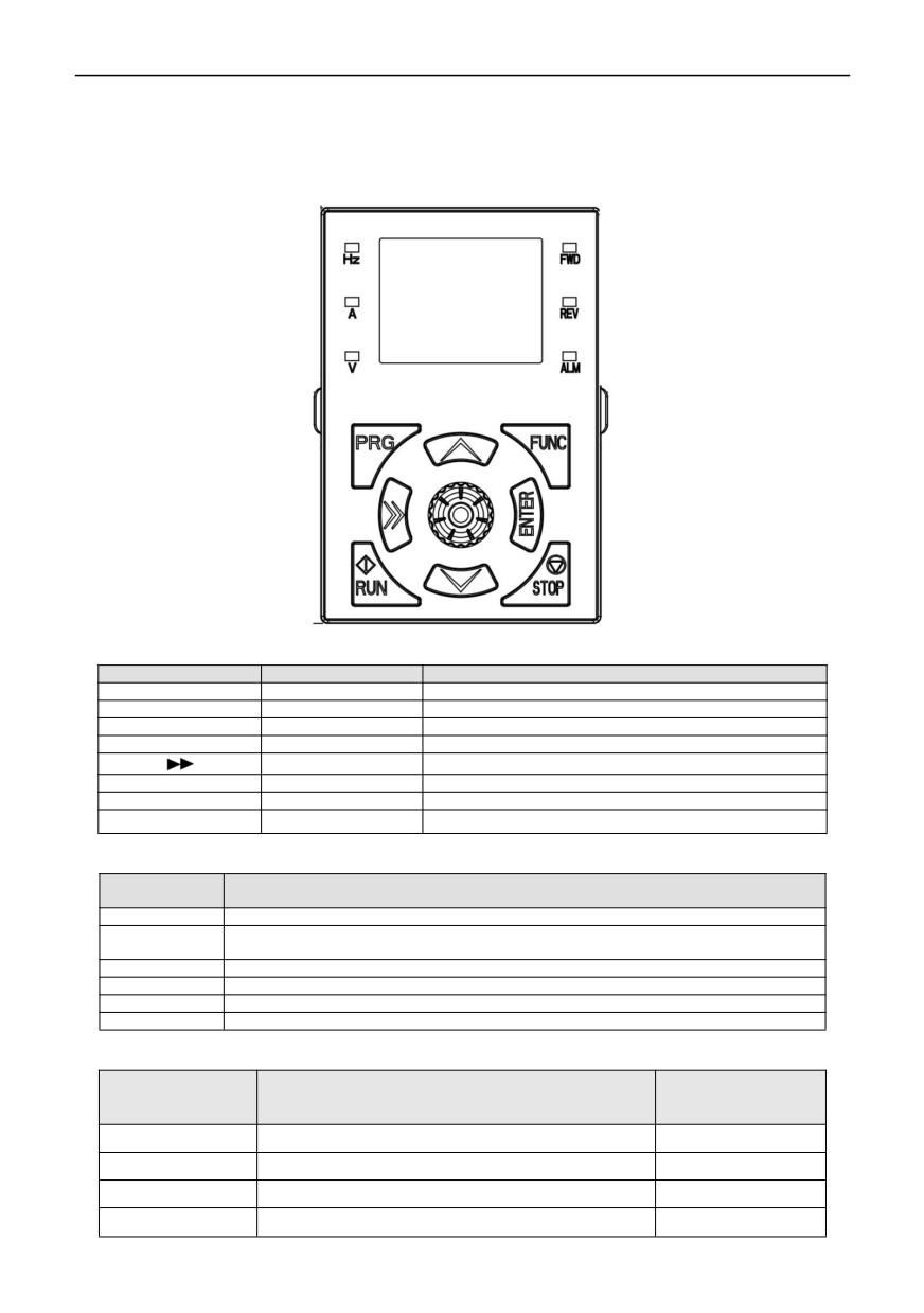
5.1.1 Diagram of keypad
5.1.2 Key Description
Key symbol
Name
Functional Description
PRG
Programming key
Menu entry or exit, parameter modification
ENTER
Confirm key
Enter the menu and confirm the parameter setting
▲
Incremental key
Increment of data or function code
▼
Decreasing key
Decrement of data or function code
Shift key
Select parameter modification bit and display content
RUN
Operation key
Operation under keyboard operation mode
STOP
Stop key
Stop operation
FUNC
Multifunctional keys
Select according to function toggle
5.1.3 Description of function indicator lamp
Indication lamp
Description
name
REV
Inverter reverse indicator lamp, which indicates reverse operation state when it is on.
Inverter forward rotation indicator lamp, when the lamp is on, it indicates forward operation
FWD
status.
ALM
Fault indicator light, which indicates that it is in a fault state.
Hz
Frequency unit
A
Current unit
V
Voltage unit
5.1.4 Description of the combination of function indicator lights:
Combination of
LED display meaning
Symbol
indicator lights
Hz+A
Revolving speed of motor
r/min
A+V
Time (seconds)
s
Hz+V
Actual value of percentage
%
Hz+A+V
Temperature
℃
20
5.2 Operation process
5.21 Parameter setting
The three-level menus are:
1. Function code group number (level 1 menu);
2. Function code label (secondary menu);
3. Set value of function code (Level 3 menu).
Note: When operating the third-level menu, press PRG or ENTER to return to the second-level menu. The difference
between them is: press ENTER to store the set parameters in the control keypad, then return to the secondary menu and
automatically transfer to the next function code; Press PRG to directly return to the secondary menu, without storing
parameters, and keep staying at the current function code.
In the third-level menu state, if the parameter has no blinking bit, it means that the function code cannot be modified.
Possible reasons are:
1) The function code is an unmodified parameter. Such as actual detection parameters, operation record parameters,
etc.
2) The function code cannot be modified in running state, and can only be modified after shutdown.
5.2.2 Fault reset
After the inverter fails, the inverter will prompt relevant fault information. The user can reset the fault through the
STOP/RESET key on the keyboard or the terminal function. After the fault is reset, the inverter is in standby mode. If the
inverter is in a fault state and the user does not reset the fault, the inverter is in a running protection state and the inverter
cannot run.
5.2.3 Self-learning of motor parameters
Choose the vector control operation mode, before the inverter runs, the nameplate parameters of the motor must be
accurately input, and the inverter matches the standard motor parameters according to the nameplate parameters; The
vector control mode is highly dependent on the motor parameters, and accurate parameters of the controlled motor must
be obtained in order to obtain good control performance.
21
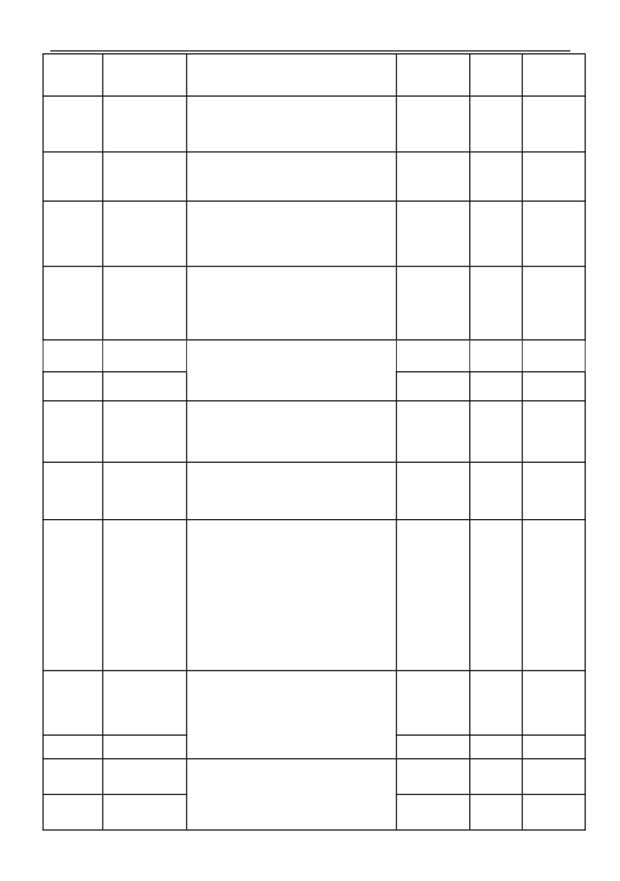
Chapter VI Functions and Parameter Table
Symbols in the menu are described as follows
×: Parameters that can be modified in any state
○: Non modifiable parameters in operation state
◆: Actual test parameter, cannot be modified
◇: The manufacturer' parameters can only be modified by the manufacturer, but not by the user.
000 group-Basic Parameters
Function
Name
Content
Setting range
Factory
Alteration
code
LCD language
0: Chinese
00.00
(only valid for LCD
0~1
0
○
1: English
keypad)
0: General model
1: Single pump constant pressure water supply mode
2: One inverter with two power (1 variable frequency
pump +2 power frequency pumps) water supply mode
3: Three-pump cycle soft start (3 variable frequency
Functional macro
pumps) water supply mode
00.01
0~20
0
×
definition
4: Solar pump water supply mode
5: CNC machine tool control mode
6: Fire patrol mode
7: EPS power mode
8~20:Reserved
Note: Please initialize parameters before setting
macro functions.
0: Common V/F Control (manual torque boost)
1: Advanced V/F Control (Automatic torque boost)
2: SVC mode(SVC)
Type
00.02
Control Mode
3: Reserved
0~4
×
setting
4: Separatable V/F Control
Note: this parameter cannot be initialized, please
modify it manually
0: The keypad runs the command channel
Run command
1: Terminal operation command channel
00.03
0~2
0
○
channel selection
2: Communication operation command channel
22
0: Digital setting 1(press keyboard key▲/▼, encoder
+00.10)
1: Digital setting 2(UP/DOWN terminals +00.10)
2: Digital setting 3(Communication setting)
3: AI1 analog setting(0~10V/20mA)
Selection of main
4: AI2 analog setting(0~10V)
00.04
frequency source
5: Pulse setting(0~50KHZ)
0~11
9
○
A
6: Simple PLC
7: Multi-speed setting
8: PID control
9: Keyboard potentiometer (Compatible encoder)
10:MPPT given (solar water pump)
11: Keyboard potentiometer
0: Digital setting 1(press keyboard key▲/▼, encoder
+00.10)
1: Digital setting 2(UP/DOWN terminals +00.10)
2: Digital setting 3(Communication setting)
3: AI1 analog setting(0~10V/20mA)
Selection of
4: AI2 analog setting(0~10V)
auxiliary
00.05
5: Pulse setting(0~50KHZ)
0~11
3
○
frequency source
B
6: Simple PLC
7: Multi-speed setting
8: PID control
9: Keyboard potentiometer (Compatible encoder)
10:MPPT given (solar water pump)
11: Keyboard potentiometer
0: Main frequency source A
1: A+K*B
2: A-K*B
3: ︱A-K*B︱
4: MAX(A,K*B)
5: MIN(A,K*B)
6: Switch from A to K*B(A takes precedence over
Frequency source
K*B)
00.06
7: Switch from A to (A+K*B)(A takes precedence over
0~8
0
○
given way
A+K*B)
8: Switch from A to (A-K*B)(A takes precedence over
A-K*B)
Note 1: Frequency switching needs to be realized
through terminal cooperation
Note 2: Compared with the given mode of this
frequency source, frequency swing control has higher
priority.
00.07
Digital setting1
LED single digit: power down store
000
○
0: store
1: not store
LED 10-digit: stop keep
0: keep
1: stop not keep
000~111
LED 100-digit: ▲/▼key、UF/DOWN negative
frequency regulation
0: invalid
1: valid
00.08
Digital setting2
000
○
LED 1000-digit: Reserved
Frequency source
This set value is the initial value of frequency digital
0.00Hz~
00.09
digital given 1
50.00
○
given 1
【00.13】
setting
23
HV100
Series High Performance Current Vector Inverter
Frequency source
This set value is the initial value of frequency digital
0.00Hz~
00.10
digital given 2
50.00
○
given 2
【00.13】
setting
Setting of auxiliary
frequency source
K is the weight coefficient of auxiliary frequency
00.11
0.01~10.00
1.00
○
weight coefficient
source
K
Low frequency
band: MAX
{50.00,
The maximum output frequency is the highest
【00.13】}~
Max output
frequency allowed by the inverter, and it is the
300.00
00.12
50.00
×
frequency
benchmark for setting the acceleration and
High frequency
deceleration time.
band: MAX
{50.0,
【00.13】}~
300.0
Upper limit
【00.14】~
00.13
Operating frequency cannot exceed this frequency
50.00
×
frequency
【00.12】
Lower limit
Operating frequency cannot be lower than this
0.00Hz~
00.14
0.00
×
frequency
frequency
【00.13】
LED single digit: High and lower frequency mode
selection
0: Lower frequency mode(0.00~300.00Hz)
1: High frequency mode(0.0~300.0Hz)
LED 10-digit: Acceleration and deceleration reference
Frequency output
selection
00.15
00~11
00
×
mode
0: Maximum output frequency
1: Target output frequency
LED 100-digit: Reserved
LED 1000-digit: Reserved
Note: High frequency mode is only effective for VF
control
0.1 ~3600.0S
Acceleration
Time required for inverter to accelerate from zero
0.4 ~4.0KW
Type
00.16
○
Time 1
frequency to maximum output frequency
7.5S
setting
5.5 ~30.0KW
15.0S
37~132KW
30.0S
Deceleration
Time required for inverter to decelerate from
Type
00.17
160~630KW
○
Time 1
maximum output frequency to zero frequency
setting
60.0S
0: Forward direction
1: Reverse direction
Running direction
00.18
2: Forbidden reverse operation
0~2
0
×
setting
Note: This function code setting is valid for running
direction control of all running command channels
1.0~16.0KHz
0.4~4.0KW
6.0KHz
When silent operation is needed, the carrier
5.5~30KW
Carrier frequency
frequency can be appropriately increased to meet the
Type
00.19
4.5KHz
○
setting
requirements, but increasing the carrier frequency will
setting
37~132KW
increase the calorific value of the inverter.
3.0KHz
160~630KW
1.8KHz
24
0~65535
Note1: 0~9: No password protection
00.20
User password
Note2: Password is set successfully, waiting for 3
0~65535
0
○
minutes to take effect
Note3: Write protection is not valid for this parameter
and cannot be initialized
01group:Start-Stop Control Parameters
Function
Name
Content
Setting range
Factory
Alteration
code
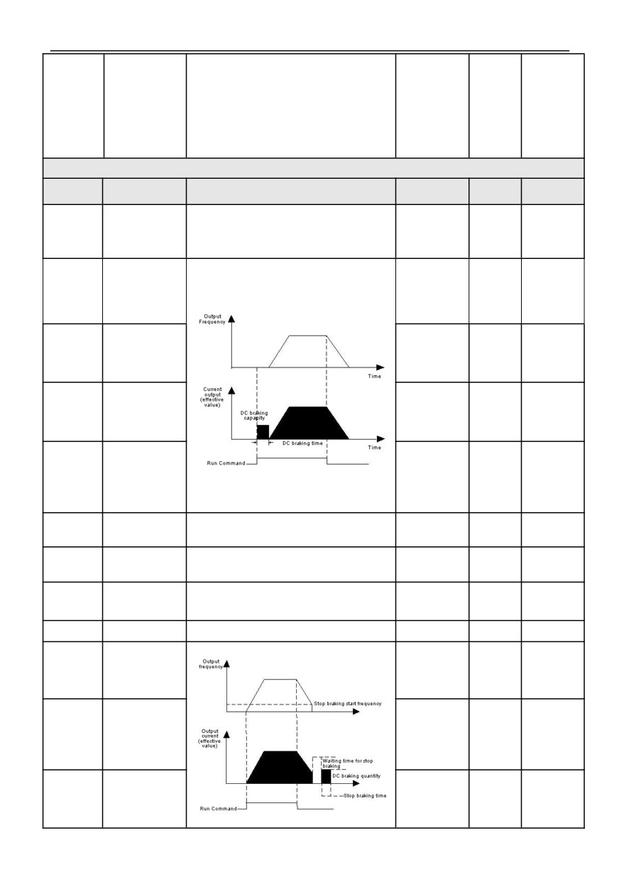
0: Starting frequency starting
01.00
Starting mode
1: DC breaking+starting frequency starting
0~2
0
×
2: Speed tracking starting
01.01
Starting frequency
0.00~50.00Hz
1.00
○
Starting frequency
01.02
0.0~100.0s
0.0
○
Holding time
Starting DC
0.0~150.0%
01.03
0.0%
○
braking current
*Rated current
Starting DC
01.04
0.0~100.0s
0.0
○
braking time
Acceleration/
0: Straight line Acceleration / Deceleration
01.05
Deceleration
0~1
0
×
1: S-Curve Acceleration / Deceleration
mode
Time proportion at
01.06
the beginning of S
Set Time proportion at the beginning of S curve
10.0~50.0%
20.0%
○
curve
Time proportion at
01.07
Set Time proportion at the end of S curve
10.0~50.0%
20.0%
○
the end of S curve
0: Deceleration to stop
01.08
Stop mode
0~1
0
×
1: Free stop
Start frequency of
0.00~【00.13】
01.09
DC braking during
Upper limit
0.00
○
stop
frequency
Waiting time for
01.10
DC braking during
0.0~100.0s
0.0
○
stop
0.0~150.0%*
01.11
DC braking current
Motor Rated
0.0%
○
current
25
HV100
Series High Performance Current Vector Inverter
Time for DC
01.12
braking during
0.0~100.0s
0.0
○
stop
Acceleration
Type
01.13
Set Acceleration Time 2
○
Time 2
setting
Deceleration
0.1~3600.0S
Type
01.14
Set Deceleration Time 2
○
Time 2
0.4~4.0KW
setting
Acceleration
7.5S
Type
01.15
Set Acceleration Time 3
○
Time 3
5.5~30KW
setting
Deceleration
15.0S
Type
01.16
Set Deceleration Time 3
○
Time 3
37~132KW
setting
Acceleration
40.0S
Type
01.17
Set Acceleration Time 4
○
Time 4
160~630KW
setting
60.0S
Deceleration
Type
01.18
Set Deceleration Time 4
○
Time 4
setting
Selection of
acceleration and
01.19
0: second
1: minute
2: 0.1second
0~2
0
○
deceleration time
unit
Jog forward
01.20
running frequency
0.00~【00.13】
5.00
○
setting
Set Jog forward running / reverse operation frequency
setting
Jog reverse
01.21
running frequency
0.00~【00.13】
5.00
○
setting
Jog Acceleration
0.1~3600.0S
Type
01.22
Set Jog Acceleration time
○
time
0.4~4.0KW
setting
7.5S
5.5~30.0KW
15.0S
37~132KW
40.0S
Jog Deceleration
Type
01.23
Set Jog Deceleration time
160~630KW
○
time
setting
60.0S
Jog Interval time
01.24
Set Jog Interval time setting
0.0~100.0s
0.1
○
setting
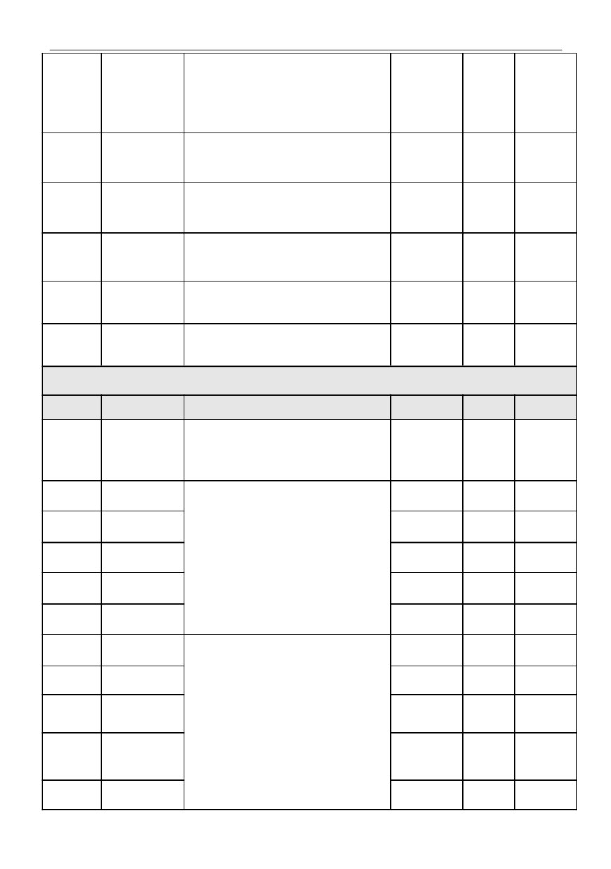
0.00~Upper
01.25
Jump frequency 1
0.00
○
limit frequency
Jump frequency 1
0.00~Upper
01.26
0.00
○
range
limit frequency
0.00~Upper
01.27
Jump frequency 2
0.00
○
limit frequency
Jump frequency 2
0.00~Upper
01.28
0.00
○
range
limit frequency
0.00~Upper
01.29
Jump frequency 3
0.00
○
limit frequency
Jump frequency 3
0.00~Upper
01.30
0.00
○
range
limit frequency
Action when the
0: Run at the lower limit frequency.
set frequency is
1: zero frequency operation after delay time
01.31
lower than the
(there is no delay when starting).
0~2
0
×
lower limit
2: Shutdown after a delay time
frequency
(there is no delay when starting).
26
HV100
Series High Performance Current Vector Inverter
Stop delay time
when frequency is
lower than lower
Set stop delay time when frequency is lower than
01.32
0.0~3600.0s
10.0
○
limit frequency
lower limit frequency (Simple dormancy)
(Simple
dormancy)
0.0~
Zero frequency
This parameter is the percentage of the rated current
01.33
150.0%*Rated
0.0
×
braking current
of the motor.
current
Forward and
The waiting time for a inverter to transition from
01.34
reverse dead zone
forward operation to reverse operation, or from
0.0~100.0s
0.0
○
time
reverse operation to forward operation.
Forward and
0: Over 0Hz frequency switching
01.35
reverse switching
1: Over start frequency switching
0~1
0
×
mode
Emergency stop
It is only valid for function No.10 in digital input
01.36
standby
0.1~3600.0s
1.0
○
terminal (07.00 ~ 07.06).
deceleration time
Current holding
time for DC
Set Current holding time for DC braking during
01.37
0.0~100.0s
0.0
○
braking during
shutdown
shutdown
002 group-Motor Parameters
Function
Name
Content
Setting range
Factory
Alteration
code
0: AC asynchronous motor
Selection of motor
1: Reserved
02.00
0~1
0
×
type
Note: This parameter cannot be initialized, please
modify it manually
Motor rated
Model
02.01
0.4~999.9KW
×
power
setting
Motor rated
0.01Hz~
02.02
50.00
×
frequency
【00.13】
Set according to the parameters of motor nameplate.
Please configure the corresponding motor according
Motor rated
Model
02.03
to the power of the inverter. If the power difference is
0~60000RPM
×
rotating speed
setting
too large, the control performance of the inverter will
obviously decrease.
Motor rated
Model
02.04
0~999V
×
Voltage
setting
Motor rated
Model
02.05
0.1~6553.5A
×
current
setting
Stator resistance
Model
02.06
of asynchronous
0.01~20.000Ω
×
setting
motor
Rotor resistance of
Model
02.07
asynchronous
0.01~20.000Ω
×
setting
motor
Inductance of
stator and rotor of
Model
02.08
0.1~6553.5mH
×
asynchronous
If the motor is tuned, the set values from 02.06 to
setting
motor
02.10 will be updated after the tuning is finished.
Mutual inductance
between stator
Model
02.09
and rotor of
0.1~6553.5mH
×
setting
asynchronous
motor
No-load current of
Model
02.10
asynchronous
0.01~655.35A
×
setting
motor
27
02.11
Reserved
—
—
0
◆
~02.15
0: No action
Motor tuning
02.16
1: Static tuning
0~2
0
×
selection
2: No-load complete tuning
Pre-excitation
holding time of
Model
02.17
Note: This parameter is invalid for VF control.
0.00~10.00S
×
asynchronous
setting
motor
003 group-Reserved
004group- Speed loop and torque control parameters
Function
Name
Content
Setting range
Factory
Alteration
code
Speed loop
04.00
(ASR1)
0.000~6.000
3.0
○
proportional gain
Speed loop(ASR1)
0.000~
04.01
0.50
○
Integral time
32.000S
04.02
ASR1 filter time
Function codes 01.00 ~ 01.07 are valid in vector
0.000~0.100S
0.000
○
constant
control without PG
Switch low point
0.00Hz~
04.03
5.00
○
frequency
【04.07】
Speed loop
04.04
(ASR2)
0.000~6.000
2.0
○
In vector control mode, the speed response
proportional gain
characteristics of vector control are changed by
Speed loop(ASR2)
setting the proportional gain p and integration time i of
0.000~
04.05
the speed regulator.
1.00
○
Integral time
32.000S
ASR2 filter time
04.06
0.000~0.100S
0.000
○
constant
Switch high point
04.03】~
04.07
10.00
○
frequency
【00.13】
Positive slip
compensation
50.0%~
04.08
coefficient of
In vector control mode, this function code parameter
100.0%
○
200.0%
vector control
is used to adjust the speed stability accuracy of the
(electric state)
motor. When the motor is overloaded and the speed
is low, increase this parameter, otherwise decrease
this parameter. The positive slip coefficient
compensates the speed when the motor slip is
positive, whereas the negative slip coefficient
Negative slip
compensates the speed when the motor slip is
compensation
negative. This set value is the percentage of the rated
50.0%~
04.09
coefficient of
100.0%
○
slip frequency of the motor.
200.0%
vector control
(braking state)
0: Speed
Selection of speed
04.10
1: Torque
0~2
0
×
and torque control
2: Condition effective (terminal switching)
Speed and torque
04.11
Set speed and torque switching delay time
0.01~1.00S
0.05
×
switching delay
0: keypad digital given
Torque command
1: AI1
04.12
0~3
0
○
selection
2: AI2
3: Communication given
28
HV100
Series High Performance Current Vector Inverter
Keyboard digital
The set value is a percentage of the rated current of
-200.0%~
04.13
0.0%
○
setting torque
the motor
200.0%
Speed limit
channel selection
0: keypad digital given1
04.14
1 for torque control
1: AI1
0~2
0
○
mode (forward
2: AI2
direction)
Speed limit
channel selection
0: keypad digital given2
04.15
1 of torque control
1: AI1
0~2
0
○
mode (reverse
2: AI2
direction)
Keyboard digital limit speed 1 to a limit relative to the
Keyboard digital
maximum output frequency. This function code
04.16
0.0~100.0%
100.0%
○
limit speed 1
corresponds to the limit value of forward speed when
04.14=0.
Keyboard digital limit speed 2 to a limit relative to the
Keyboard digital
maximum output frequency. This function code
04.17
0.0~100.0%
100.0%
○
limit speed 2
corresponds to the limit value of reverse speed when
04.15=0.
04.18
Torque rise time
0.0~10.0S
0.1
○
Torque rise/down time defines the time when the
torque rises from 0 to the maximum value or falls from
the maximum value to 0.
04.19
Torque fall time
0.0~10.0S
0.1
○
G type: 0.0%~
Electric torque
Set the Electric torque limit of vector mode, which is a
200.0%160.0%
Type
04.20
limitation in vector
○
percentage of the rated current of the motor.
P type: 0.0%~
setting
mode
200.0%120.0%
G type: 0.0%~
Brake torque
Set the brake torque limit of vector mode, which is a
200.0%160.0%
Type
04.21
limitation in vector
○
percentage of the rated current of the motor.
P type: 0.0%~
setting
mode
200.0%120.0%
0: Detection invalid
1: Continue to run after detecting torque at constant
speed
2: Continue to run after detecting torque during
operation
3: Cut off the output after the torque is detected at
constant speed
Torque detection
4: Cut off the output after detecting torque in operation
04.22
0~8
0
×
action selection
5: Continue running after insufficient torque is
detected at constant speed
6: Continue to run after insufficient torque is detected
during operation
7: Cut off the output after detecting insufficient torque
at constant speed
8: Cut off the output after detecting insufficient torque
during operation
G type: 0.0%~
When the actual torque is within
04.24
(torque
Torque detection
detection time) and continuously exceeds
04.23
200.0%150.0%
Type
04.23
×
level
(torque check out level), the inverter will make
P type: 0.0%~
setting
corresponding actions according to the setting of
200.0%110.0%
04.22. When the set value of torque detection level is
100%, it corresponds to the rated torque of the motor.
Torque detection
04.24
0.0~10.0S
0.0
×
time
Cutoff frequency
As the starting torque of the motor is not enough,
0.00~
04.25
of static friction
10.00
○
increasing the set value of 04.26 can increase the
300.00Hz
coefficient
starting torque. When the speed exceeds the set
value of
04.25, the increased torque will slowly
Setting of static
decrease to the given torque within the set time of
04.26
0.0~200.0
0.0
○
friction coefficient
04.27.
29
HV100
Series High Performance Current Vector Inverter
Static friction
04.27
coefficient
0.00~600.00s
0.00
×
maintenance time
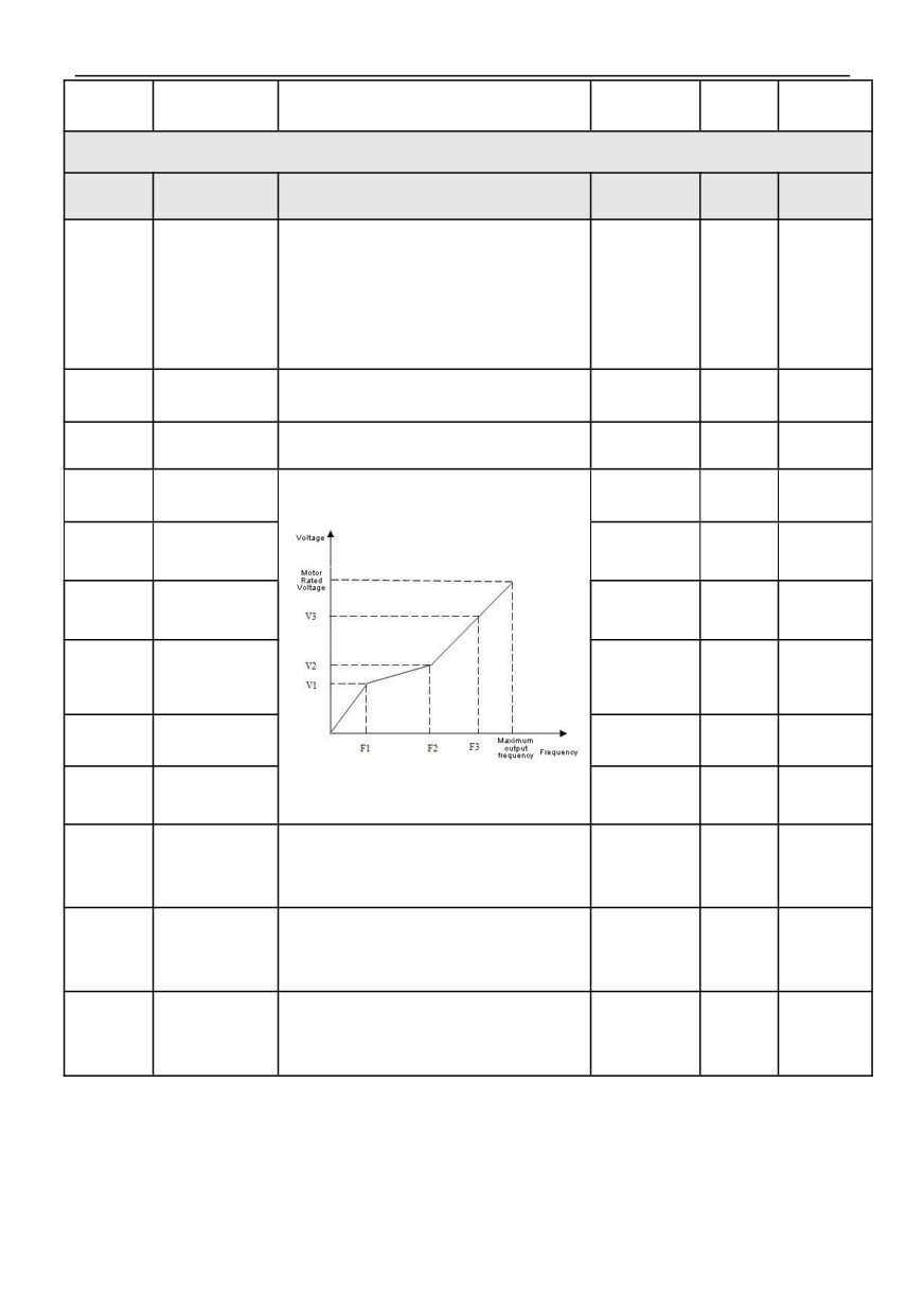
005Group-V/F Control Parameter
Function
Name
Content
Setting range
Factory
Alteration
code
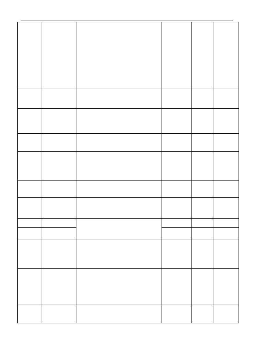
0: Linear curve
1: Torque reduction curve 1(1.3 power)
2: Torque reduction curve 1(1.5 power)
05.00
V/F curve setting
3: Torque reduction curve 1(1.7 power)
0~5
0
×
4: Square curve
5: V/F curve set by user (determined from 05.01 to
05.06)
Torque boost
Manual torque boost. This setting is a percentage
Model
05.01
0.0~30.0%
×
setting
relative to the rated voltage of the motor.
setting
Torque boost
0.00~Rated
05.02
Set Cutoff frequency of torque boost
15.00
×
cutoff frequency
frequency
0.00~
05.03
V/F frequency F1
Frequency
12.50
×
value F2
05.04
V/F voltage V1
0.0~V2
25.0%
×
Frequency
value 01~
05.05
V/F frequency F2
25.00
×
Frequency
value F3
05.06
V/F voltage V2
V1~V3
50.0%
×
Frequency
05.07
V/F frequency F3
value 01~
37.50
×
【02.02】
V2~100.0%*
05.08
V/F voltage V3
75.0%
×
rated volt
The speed of asynchronous motor will decrease after
V/F control slip
being loaded. Slip compensation can make the speed
0.0~200.0%*
05.09
frequency
0.0%
○
of motor close to its synchronous speed, thus making
rated speed
compensation
the speed control accuracy of motor higher.
This parameter is used to adjust the response speed
V/F control slip
of slip frequency compensation. The larger the setting
05.10
frequency filter
1~10
3
○
of this value, the slower the response speed and the
coefficient
more stable the motor speed.
V/F control torque
When the free torque increases, this parameter is
frequency
used to adjust the response speed of torque
Type
05.11
0~10
○
compensation
compensation. The larger this value is, the slower the
setting
filter coefficient
response speed and the more stable the motor speed.
30
HV100
Series High Performance Current Vector Inverter
0: VF semi-separated mode, voltage open loop output
1: VF semi-separated mode, voltage closed loop
output
2: VF fully separated mode, voltage open-loop output
3: VF fully separated mode, voltage closed-loop
output
Selection of
Note 1: When VF separate control is selected, please
05.12
separate V/F
turn off the dead zone compensation function of the
0~3
0
×
control
inverter
Note 2: The concept of semi-separation is that the
frequency and voltage of the inverter still maintain the
relationship of frequency conversion and
transformation during starting. When the frequency
reaches the set frequency, the voltage and frequency
are separated
0: Digital given
Voltage given
05.13
1: AI1
0~2
0
○
channel
2: AI2
0: AI1
Voltage feedback
1: AI2
05.14
channel of voltage
0~1
0
×
Note: this parameter is only valid for closed-loop
closed-loop output
output mode
Digitally set the
In the open-loop output mode, the maximum output
0.0~200.0%*
05.15
output voltage
100.0%
○
voltage is 100.0% of the rated voltage of the motor.
rated volt
value
Used to limit the maximum deviation amplitude of
Deviation limit of
voltage regulation in closed-loop mode, so as to limit
0.0~5.0%*
05.16
motor closed-loop
2.0%
×
the voltage within a safe range and ensure the reliable
rated volt
adjustment
operation of equipment.
Maximum voltage
of VF curve in
This voltage represents the output voltage of the
0.0~100.0%*
05.17
80.0%
×
semi-separated
inverter
rated volt
mode
Controller
This function code represents the speed of voltage
adjustment period
05.18
adjustment. If the voltage response is slow, this
0.01~10.00s
0.10
×
of voltage
parameter value can be appropriately reduced.
closed-loop output
05.19
Voltage rising time
0.1~3600.0S
10.0
○
05.19 ~ 05.20 is only valid for the voltage open-loop
output mode after complete separation.
05.20
Voltage drop time
0.1~3600.0S
10.0
○
0: Alarm and maintain operation with the voltage at
Voltage feedback
the time of disconnection
05.21
disconnection
1: Alarm and reduce the voltage to limiting voltage for
0~2
0
×
processing
operation
2: Protective action and free parking
The maximum value of the given voltage is taken as
the upper limit value of the feedback disconnection
Voltage feedback
detection value. In the feedback disconnection
0.0~100.0%*
05.22
disconnection
detection time, when the voltage feedback value is
2.0%
○
detection value
continuously less than the feedback disconnection
rated volt
detection value, the inverter will make corresponding
protection actions according to the setting of 05.21.
Voltage feedback
Duration before protection action after voltage
05.23
disconnection
0.0~100.0S
10.0
○
feedback disconnection.
detection time
31
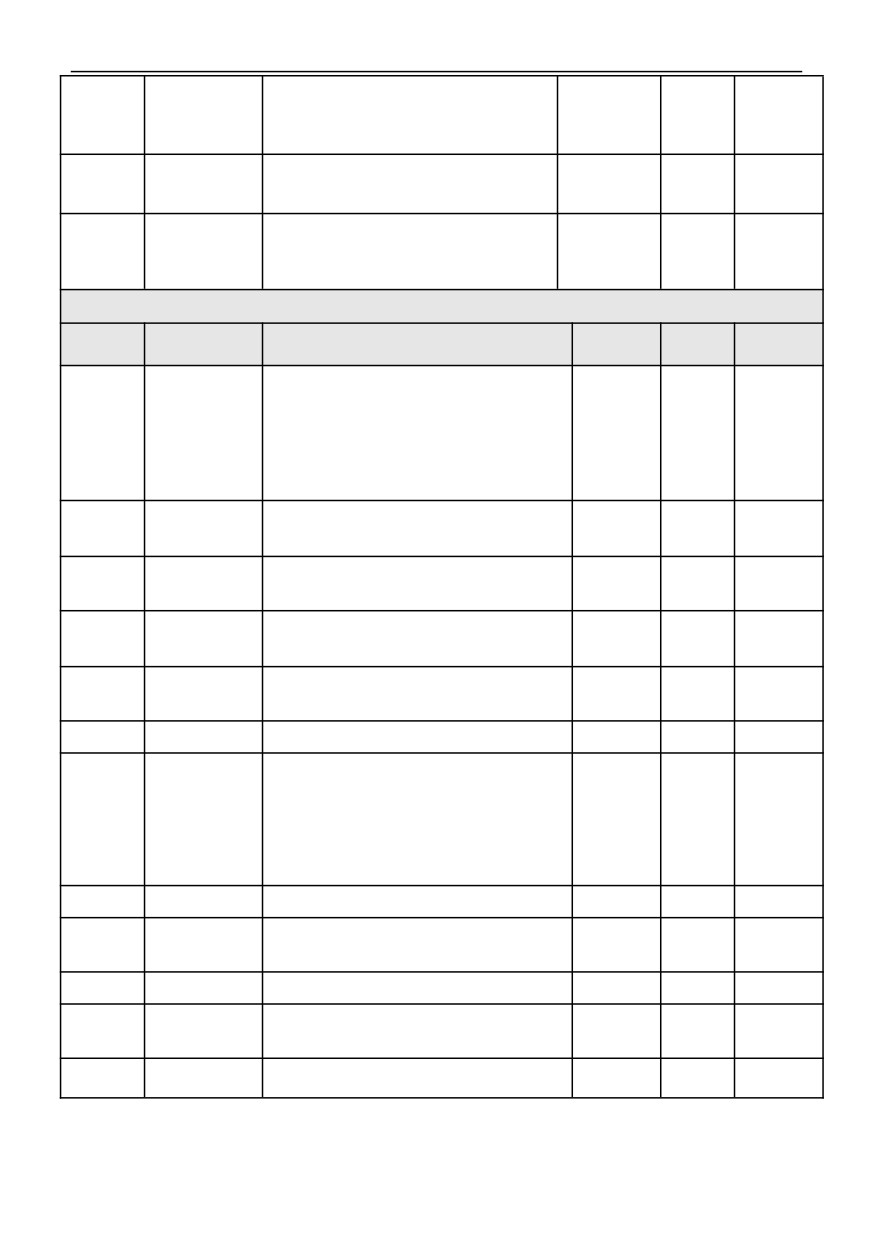
This voltage represents the output voltage of the
Limiting voltage of
inverter, and setting this parameter reasonably can
0.0~100.0%*
05.24
voltage feedback
80.0%
○
prevent equipment damage caused by voltage
rated volt
disconnection
overshoot at the time of disconnection.
DC Bus
If DC bus voltage less than the parameter value,the
05.25
undervoltage
system will report "E-34".
0~1000V
0
○
detection value
If the parameter value set 0, the function is invalid.
If DC bus voltage is the equals of the parameter
Reset DC Bus
05.26
value,the system will reset the fault "E-34"and run
0~1000V
0
○
undervoltage fault
automatically.
006 group-Analog and pulse input and output parameters
Function
Setting
Name
Content
Factory
Alteration
code
range
0: Speed command(output frequency,-100.0%~
AI1 input
100.0%)
06.00
corresponding
1: Torque command(output torque,-200.0%~200.0%)
0~2
0
×
physical quantity
2: Voltage command(output voltage, 0.0%~200.0%*
Rated voltage)
0.00V/0.00m
AI1 input lower
A~
06.01
Set AI1 lower limit
0.00
○
limit
10.00V/20.0
0mA
AI1 lower limit
corresponds to
Set AI1 lower limit corresponding setting, which
-200.0%~
06.02
0.0%
○
physical quantity
corresponds to the percentage of upper limit frequency.
200.0%
setting
0.00V/0.00m
AI1 input upper
A~
06.03
Set AI1 upper limit
10.00
○
limit
10.00V/20.0
0mA
AI1 upper limit
corresponds to
Set AI1 upper limit corresponding setting, which
-200.0%~
06.04
100.0%
○
physical quantity
corresponds to the percentage of upper limit frequency.
200.0%
setting
AI1 input Filter
0.00S~
06.05
Set AI1 Filter time
0.05
○
time
10.00S
0: Speed command(output frequency,-100.0%~
AI2 input
100.0%)
06.06
corresponding
1: Torque command(output torque,-200.0%~200.0%)
0~2
0
×
physical quantity
2: Voltage command(output voltage, 0.0%~200.0%*
Rated voltage)
AI2 input lower
0.00V~
06.07
Set AI2 lower limit
0.00
○
limit
10.00V
AI2 lower limit
corresponds to
Set AI2 lower limit corresponding setting, which
-200.0%~
06.08
0.0%
○
physical quantity
corresponds to the percentage of upper limit frequency.
200.0%
setting
AI2 input upper
0.00V~
06.09
Set AI2 upper limit
10.00
○
limit
10.00V
AI2 upper limit
corresponds to
Set AI2 upper limit corresponding setting, which
-200.0%~
06.10
100.0%
○
physical quantity
corresponds to the percentage of upper limit frequency.
200.0%
setting
AI2 input Filter
Set AI2 Filter time
0.00S~
06.11
0.05
○
time
10.00S
32
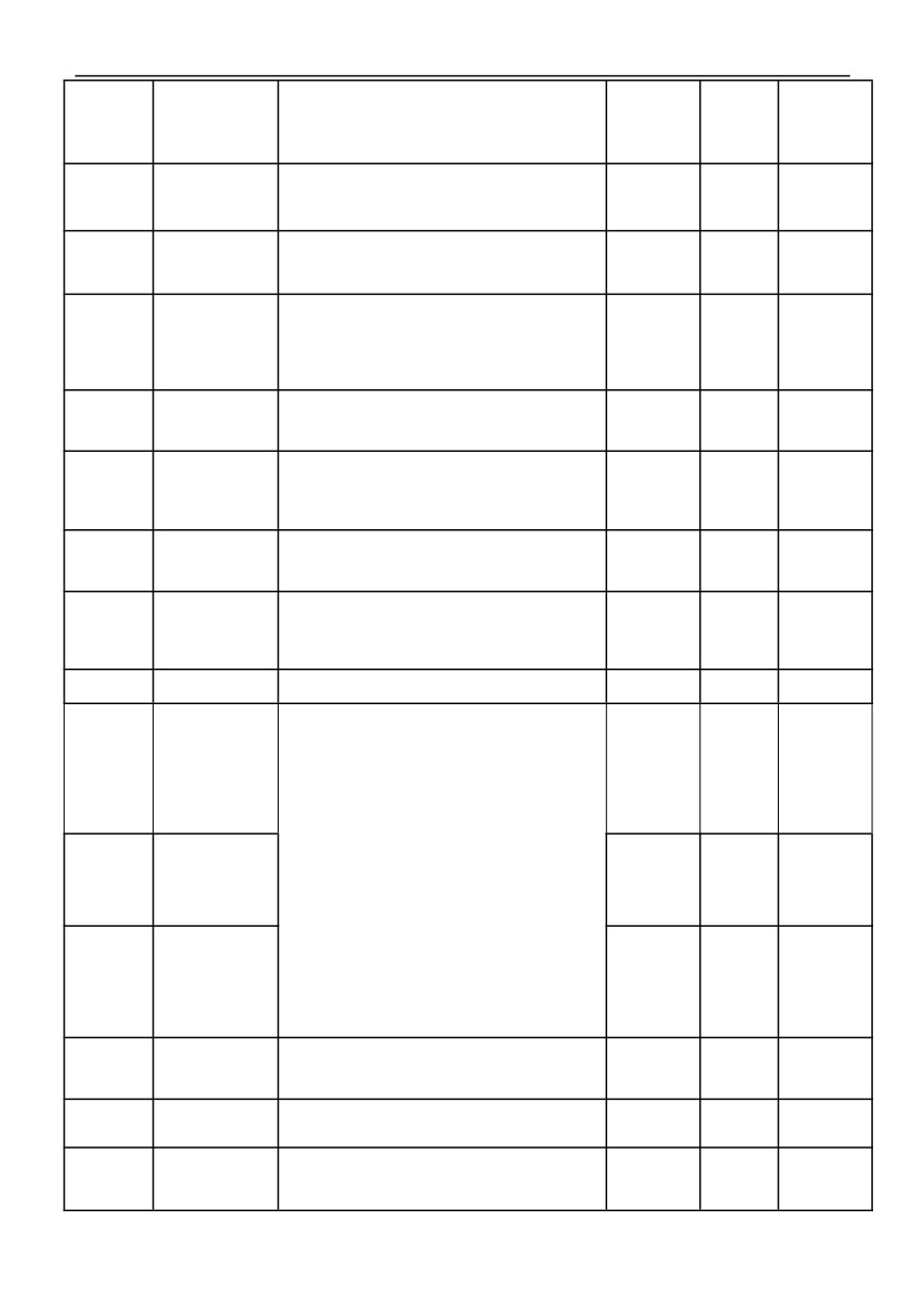
HV100
Series High Performance Current Vector Inverter
Analog input
When the analog input signal fluctuates frequently near a
0.00V~
06.12
anti-shake
given value, the frequency fluctuation caused by this
0.00
○
10.00V
deviation limit
fluctuation can be suppressed by setting 06.12.
Zero
Zero frequency
When 00.15=1 (high frequency mode), the maximum
frequency
06.13
operation
0.00
○
value of this function code is 500.0Hz.
backlash~
threshold
50.00Hz
0.00~Zero
Zero frequency
frequency
06.14
Set Zero frequency return difference
0.00
○
return difference
operation
threshold
External pulse
0: Speed command(output frequency,-100.0%~
input corresponds
06.15
100.0%)
0~1
0
×
to physical
1: Torque command(output torque,-200.0%~200.0%)
quantity
Lower limit of
0.00~
06.16
external pulse
Set the input lower limit frequency of external pulse HDI
0.00
○
50.00kHz
input
The lower limit of
external pulse
Set the external pulse HDI lower limit to the
-200.0%~
06.17
corresponds to the
corresponding setting, which is a percentage relative to
0.0%
○
200.0%
setting of physical
the maximum output frequency.
quantity
upper limit of
0.00~
06.18
external pulse
Set the upper limit frequency of external pulse HDI input
50.00
○
input
50.00kHz
The upper limit of
external pulse
Set the external pulse HDI upper limit to the
-200.0%~
06.19
corresponds to the
corresponding setting, which is a percentage relative to
100.0%
○
200.0%
setting of physical
the maximum output frequency.
quantity
External pulse
0.00S~
06.20
Set External pulse input filtering time
0.05
○
input filtering time
10.00S
0: Output frequency (before slip compensation)
Function Selection
of AO1
1: Output frequency (after slip compensation)
06.21
Multifunctional
2: Set frequency
0~14
0
○
Analog Output
Terminal
3: Motor speed (estimated value)
4: Output current
5: Output voltage
Function Selection
6: DC Bus Voltage
of AO2
7: PID given value
06.22
Multifunctional
0~14
4
○
Analog Output
8: PID feedback value
Terminal
9: AI1
10: AI2
Function selection
11: Input pulse frequency
of HDO
12: Torque current
06.23
multi-function
0~14
11
○
pulse output
13: Flux current
terminal
14: Communication setting
AO1 output lower
limit corresponds
Set AO1 output lower limit corresponds to physical
-200.0%~
06.24
0.0%
○
to physical
quantity
200.0%
quantity
AO1 output lower
0.00~
06.25
Set AO1 output lower limit
0.00
○
limit
10.00V
AO1 output upper
limit corresponds
Set AO1 output upper limit corresponds to physical
-200.0%~
06.26
100.0%
○
to physical
quantity
200.0%
quantity
33
AO1 output upper
0.00~
06.27
Set AO1 output upper limit
10.00
○
limit
10.00V
AO2 output lower
limit corresponds
Set AO2 output lower limit corresponds to physical
-200.0%~
06.28
0.0%
○
to physical
quantity
200.0%
quantity
AO2 output lower
0.00~
06.29
Set AO2 output lower limit
0.00
○
limit
10.00V
AO2 output upper
limit corresponds
Set AO2 output upper limit corresponds to physical
-200.0%~
06.30
100.0%
○
to physical
quantity
200.0%
quantity
AO2 output upper
0.00~
06.31
Set AO2 output upper limit
10.00
○
limit
10.00V
DO output lower
limit
Set DO output lower limit corresponding to physical
-200.0%~
06.32
corresponding to
0.0%
○
quantity
200.0%
physical quantity
(reservation)
DO output lower
0.00~
06.33
Set DO output lower limit
0.00
○
limit (reservation)
50.00kHz
DO output upper
limit
Set DO output upper limit corresponding to physical
-200.0%~
06.34
corresponding to
100.0%
○
quantity
200.0%
physical quantity
(reservation)
DO output uppper
0.00~
06.35
Set DO output uppper limit
50.00
○
limit (reservation)
50.00kHz
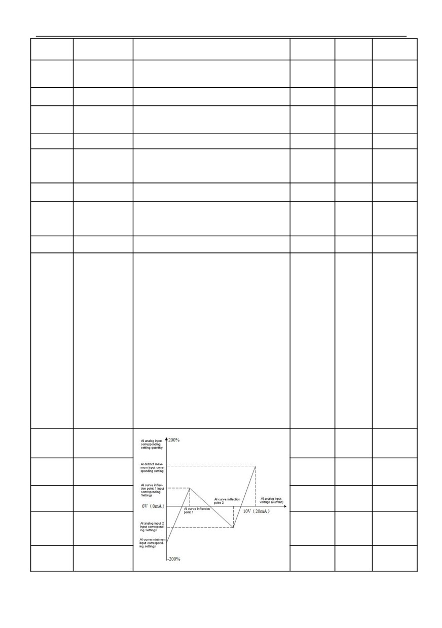
LED single digit: AI1 Multi point curve selection
0: Forbidden
1:Effective
LED10-digit: AI2 Multi point curve selection
0: Forbidden
AI Related
1:Effective
06.36
parameters
000~311
000
×
selection
LED100-digit: constant of analog signal selection
0: AI1 and AI2 input analog 0~10V
1:AI1input analog 4~20mA, AI2 input analog 0~10V
2: AI2 input analog 4~20mA, AI1 input analog0~10V
3: AI1 and AI2 input analog 4~20V
LED1000-digit: Reserved
AI1 curve
0.00~
06.37
0.00
○
minimum input
【06.39】
AI1 curve
minimum input
-200.0%~
06.38
0.0%
○
corresponding
200.0%
setting
AI1 curve
【06.37】~
06.39
inflection point 1
3.00
○
input
【06.41】
AI1 curve
inflection point 1
-200.0%~
06.40
input
30.0%
○
200.0%
corresponding
setting
AI1 curve
【06.39】~
06.41
inflection point 2
6.00
○
input
【06.43】
34
HV100
Series High Performance Current Vector Inverter
AI1 curve
inflection point 2
-200.0%~
06.42
input
60.0%
○
200.0%
corresponding
setting
AI1 curve
【06.41】~
06.43
10.00
○
maximum input
10.00
AI1 curve
maximum input
-200.0%~
06.44
100.0%
○
corresponding
200.0%
setting
AI2 curve
0.00~
06.45
0.00
○
minimum input
【06.47】
AI2 curve
minimum input
-200.0%~
06.46
0.0%
○
corresponding
200.0%
setting
AI2 curve
【06.45】~
06.47
inflection point 1
3.00
○
【06.49】
input
AI2 curve
inflection point 1
-200.0%~
06.48
input
30.0%
○
200.0%
corresponding
setting
AI2 curve
【06.47】~
06.49
inflection point 2
6.00
○
【06.51】
input
AI2 curve
inflection point 2
-200.0%~
06.50
input
60.0%
○
200.0%
corresponding
setting
AI2 curve
【06.49】~
06.51
10.00
○
maximum input
10.00
AI2 curve
maximum input
-200.0%~
06.52
100.0%
○
corresponding
200.0%
setting
0.00V/0.00m
AI1 input voltage
A~
06.53
protection upper
6.80
○
limit
10.00V/20.0
When the value of analog input AI1 is greater than 06.53,
0mA
or AI1 input is less than 06.54, the inverter Y terminal or
relay R outputs "AI1 input overrun" ON signal, which is
used to indicate whether the AI1 input voltage is within
0.00V/0.00m
AI1 input voltage
the set range.
A~
06.54
protection lower
3.10
○
limit
10.00V/20.0
0mA
007group-digital input and output parameters
Function
Setting
Name
Content
Factory
Alteration
code
range
0: None
1: Forward rotation control(FWD)
Input terminal DI1
2: Reverse rotation control(REV)
function (when
3: Three-wire control
07.00
00.01 is 2 or 3, the
0~65
1
×
default function is
4: Forward jog control
58)
5: Reverse jog control
6: Free stop control
7: External rest signal input(RST)
35
HV100
Series High Performance Current Vector Inverter
8: External equipment fault normally open (NO) input
9: External equipment fault normally close (NC) input
10: Emergency stop function (brake at the fastest speed)
11: External stop control
Input terminal DI2
12: Frequency increase control(UP)
function (when
13: Frequency decrease control(DOWN)
07.01
00.01 is 2 or 3, the
0~65
2
×
default function is
14: UP/DOWN terminal frequency clear
59)
15: Multi-speed selection1
16: Multi-speed selection2
17: Multi-speed selection3
18: Multi-speed selection4
19: Acc/Dec time selection TT1
20: Acc/Dec time selection TT2
21: Run command1
22: Run command2
23: Forbidden acceleration/deceleration
Input terminal DI3
function (when
24: Inverter run forbidden command
07.02
00.01 is 2 or 3, the
0~65
4
×
25: Switch to keypad run command
default function is
60)
26: Switch terminal run command
27: Switch communicate run command
28: Auxiliary frequency reset
29: Frequency source A switch to K*B
30: Frequency source A switch to A+K*B
31: Frequency source A switch to A-K*B
32: Reserved
Input terminal DI4
33: PID control input
Power (when
34: PID control pause
07.03
00.01 is 2 or 3, the
0~65
7
×
35: Swing frequency control input
default function is
61)
36: Swing frequency control pause
37: Rest Swing frequency status
38: PLC control input
39: PLC pause
40: PLC reset
Input terminal DI5
41: Count clearance signal
function (when
07.04
00.01 is 2 or 3, the
42: Count trigger signal
0~65
8
×
default function is
43: Timing trigger signal
62)
44: Timing clearance signal
45: Pulse frequency signal (only valid for HDI )
46: Length clearance
47: Length count signal (only valid for HDI )
Input terminal DI6
48: Speed torque switch
function (when
49: Torque control forbidden
07.05
00.01 is 2 or 3, the
0~65
0
×
default function is
50~57: Reserved
63)
58: Start/Stop
59: Operating permits
60: Interlock1
61: Interlock2
62: Interlock2
63: PFC start/stop
64: Frequency source A is switched to B and run
HDI function of
input terminal
65: PID 1 switch to PID 2
07.06
0~65
45
×
(high speed pulse
input)
07.07
Reserved
—
—
0
◆
07.08
Times of DI
1: Represents 2ms scanning time unit
1~10
5
○
36
HV100
Series High Performance Current Vector Inverter
filtering
Selection of
terminal function
0: Terminal running command is invalid when power on
07.09
0~1
0
○
detection when
1: Terminal running command is valid when power on
power on
0 means positive logic, that is, the Xi terminal is
connected with the public terminal effectively, and the
Input logic set
disconnection is invalid
07.10
0~7FH
00
×
(DI1~HDI)
1 means anti-logic, that is, the connection between Xi
terminal and public terminal is invalid, and the
disconnection is effective
0: Two-line control mode1
1: Two-line control mode2
07.11
FWD/REV mode
0~3
0
×
2: Three-wire control mode1
3: Three-wire control mode2
UF/DOWN
When 00.15=1 (high frequency mode), the maximum
0.01~
07.12
terminal frequency
1.00
○
modification rate
value of this function code is 500.0Hz/s:.
50.00Hz/S
07.13
Reserved
—
—
0
◆
Y1 output delay
07.14
0.0~100.0s
0.0
×
time
07.15
Y2 output delay
This function code defines the time delay from the
0.0~100.0s
0.0
×
time
change of state of terminals Y1 and Y2 and relays R1
R1 output delay
07.16
and R2 to the change of output.
0.0~100.0s
0.0
×
time
R2 output delay
07.17
0.0~100.0s
0.0
×
time
0: None
1: FWD run
2: REV run
3: Fault output
4 Frequency/speed detection signal (FDT1)
Open collector
5:Frequency/speed detection signal (FDT2)
07.18
output terminal Y1
6: Frequency/speed arrival signal (010R)
0~62
0
×
setting
7: Indication in zero speed operation of inverter
8: Out frequency upper limit
9: Out frequency lower limit
10: The lower limit value of the set frequency reaches at
runtime
11: Overload alarm signal of inverter
12: Counter detection output
13: Counter reset output
14: Inverter ready to run 1
15: Programmable multi-speed operation is completed in
one cycle
16: Programmable multi-speed stage operation
Open collector
07.19
output terminal Y2
completed
0~62
0
×
setting
17: Swing frequency upper and lower limit
18: Current limiting operation
19: Over voltage stall action
20: Under-voltage lockout stop
21: Sleeping
22: Alarm signal (PID disconnection, RS485
37
HV100
Series High Performance Current Vector Inverter
communication failure, keypad communication failure,
EEFROM reading and writing failure, encoder
disconnection alarm, etc.)
23: AI1>AI2
24: length reach output
25: Timing time arrives
26: Dynamic braking action
Programmable
07.20
0~62
3
×
27: DC braking action
relay R1 output
28: Flux braking in action
29: Torque is being limited
30: Over torque indication
31: Auxiliary motor 1
32: auxiliary motor 2
33: Accumulated running time reached
34~49: Multi-stage speed or simple PLC operation
stage number indication
50: Running indicator signal
51: Temperature reached indication
52: Indication when the inverter is stopped or running at
zero speed
53: reserved
54: reserved
Programmable
55: Communication settings
07.21
0~62
0
×
relay R2 output
56: The inverter is ready for operation 2
57: AI1 input limit exceeded
58: The output current exceeds the limit
59: Interlock 1 output
60: Interlock 2 output
61: Interlock 3 output
62: Output when frequency and current detection level
arrive at the same time
0: means positive logic,that is, the connection between:
Effective logic
Yi terminal and public terminal is effective, and the
disconnection is invalid
07.22
setting of output
0~3H
0
×
1: means negative logic, that is, the connection between:
terminal (Y1~Y2)
Yi terminal and public terminal is invalid, and the
disconnection is effective
The frequency
0.0~
07.23
reaches the FAR
100.0%*
10.0%
○
detection width
【00.13】
FDT1 detection
0: Frequency set value
07.24
0~1
0
○
mode
1: Frequency test value
38
0.00Hz~
07.25
FDT1 level set
50.00
○
【00.13】
0.0~
07.26
FDT1 lag value
100.0%*
2.0%
○
【07.25】
FDT2 detection
0: Frequency set value
07.27
0~1
0
○
mode
1: Frequency test value
0.00Hz~
07.28
FDT2 level set
25.00
○
【00.13】
Refer to 07.25 ~ 07.26 schematic diagram.
0.0~
07.29
FDT2 lag value
100.0%*
4.0%
○
【07.28】
0: Stop counting, stop output
1: Stop counting, continue to output
07.30
Counter reach
0~3
3
×
2: Cycle counting, stop output
3: Cycle counting, continue to output
Counter start
0: Always start after power-on
07.31
0~1
1
×
condition
1: Start when running, stop when stopping
Counter reset
【07.33】~
07.32
This function code defines the count reset value and
0
○
value setting
65535
detection value of the counter. When the count value of
the counter reaches the value set by function code
11.21, the corresponding multi-function output terminal
(counter reset signal output) outputs an effective signal
07.33
Counter detection
and clears the counter.
0~【07.32】
0
○
value setting
0: Stop timing, stop output
1: Stop timing, continue to output
07.34
Timing time reach
0~3
3
×
2: Cycle timing, stop output
3: Cycle timing, continue to output
0: Always start
07.35
Timing start
0~1
1
×
1: Run start Stop stop
07.36
Timing timer
Set Timing timer
0~65535s
0
○
07.37
Y1 OFF delay time
0.0~100.0s
0.0
×
07.38
Y2 OFF delay time
This function code defines the time delay from the
0.0~100.0s
0.0
×
change of state of switch output terminals Y1 and Y2 and
07.39
R1 OFF delay time
relays R1 and R2 to the change of output.
0.0~100.0s
0.0
×
07.40
R2 OFF delay time
0.0~100.0s
0.0
×
39