HV100 Series Frequency Inverter. User Manual (V4.0) - page 1
Contents
Contents
1
Chapter I Safety Information
3
1.1 Marks and definitions of safety information
3
1.2 Use range
3
1.3 Installation Environment
3
1.4 Installation safety matters
4
1.5 Use safety matters
5
Chapter II Standard Specifications of Products
6
2.1 Technical specifications
6
2.2 Inverter model description
9
2.3 Size of chassis and keyboard
9
2.4 Rated current output meter
11
2.5 Selection of Braking Resistance Table
11
Chapter III Storage and Installation
13
3.1 Storage
13
3.2 Installation site and environment
13
3.3 Installation space and direction
13
Chapter IV Wiring
14
4.1 Main circuit wiring diagram
14
4.2 Connecting terminal Figure
14
4.2.1 The function description of the main circuit terminal is as follows:
14
4.2.2 The terminal for controlling loop
15
4.2.3 Jumper settings of main control board
16
4.3 Basic wiring diagram
16
4.4 Matters needing attention for Wiring
18
4.4.1 Main circuit wiring
17
4.4.2 Control circuit wiring (signal line)
18
4.4.3 Grounding wire
19
4.5 Matters needing attention for specific application
18
4.5.1 Type selection
19
4.5.2 Matters needing attention in motor use
19
Chapter V Operation and display
20
5.1 keypad description
20
5.1.1 Diagram of keypad
20
5.1.2 Key Description
20
5.1.3 Description of function indicator lamp
20
5.2 Operation process
21
5.21 Parameter setting
21
5.2.2 Fault reset
21
5.2.3 Self-learning of motor parameters
21
Chapter VI Functions and Parameter Table
22
Chapter VIII EMC (Electromagnetic Compatibility)
60
8.1 Definitions
129
8.2 Introduction to EMC Standards
126
1
8.3 EMC guidance
126
8.3.1 Influence of harmonics:
126
8.3.2 Electromagnetic interference and installation precautions:
126
8.3.3 Treatment method of interference of peripheral electromagnetic equipment
126
8.3.4 Measures to deal with interference caused by inverter to peripheral equipment:
126
8.3.5 Leakage current and treatment:
127
8.3.6 Precautions for installing EMC input filter at power input end:
130
Chapter IX Fault Diagnosis and Countermeasures
128
9.1 Fault Alarm and Countermeasures
128
9.2 Exception handling
130
Appendix 1: Modbus communication protocol
131
Appendix 2: Description of macro parameter setting
144
Appendix 3: Parameter description of soft start water supply of three pump circulation
144
Warranty agreement
146
2
Chapter I Safety Information
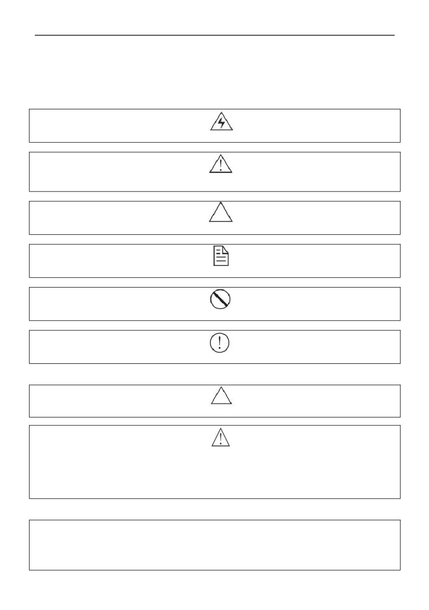
1.1 Marks and definitions of safety information
The safety clauses described in this User‘s manual are very important, which can ensure you to use the inverter safely,
and prevent yourself or the people around you from being hurt and the property in the working area from being damaged.
Please be fully familiar with the following icons and meanings, and be sure to observe the precautions indicated, and then
continue to read this user‘s manual.
Danger
This symbol indicates that failure to operate as required may cause death or serious injury.
Warning
This symbol indicates that if you do not operate as required, it will cause moderate personal injury or minor injury and
certain material loss.
Attention
This symbol indicates matters needing attention in operation or use.
Prompt
This symbol prompts the user with some useful information.
The following two icons are supplementary descriptions of the above signs:
Prohibition
It means something that must not be done.
Enforcement
Indicates something that must be done.
1.2. Use range
Attention
This inverter is suitable for general industrial three-phase AC asynchronous motors.
Warning
● And in equipment (nuclear power control equipment, aerospace equipment, transportation equipment, life support
system, safety equipment, weapon system, etc.) which may threaten life or harm human body due to inverter failure or
working error, please consult our company in advance for special purpose.
● This product is manufactured under the strict supervision of the quality management system, but safety protection
measures must be taken to prevent the inverter from expanding the scope of the accident when it is used in important
equipment.
1.3 Installation Environment
● is installed indoors and in well-ventilated places, and should be installed vertically to ensure the best cooling effect.
additional ventilation devices may be required in horizontal installation.
● The environmental temperature should be within the range of-10 ~ 40℃. If the temperature exceeds 40℃, please
remove the upper cover. If the temperature exceeds 50℃, it needs external forced heat dissipation or derating. Users are
advised not to use the inverter in such a high temperature environment, because this will greatly reduce the service life of
the inverter.
3
● The environmental humidity is required to be lower than 90%, and there is no condensation of water droplets.
● it is installed in a place with vibration less than 0.5G to prevent falling damage. The inverter is not allowed to suffer
sudden impact.
● it is installed in an environment far away from electromagnetic fields and free of inflammable and explosive
substances.
1.4 Installation safety matters
Danger
● Do not work with wet hands.
● It is strictly forbidden to carry out wiring operations without completely disconnecting the power supply.
● When the inverter is powered on, please do not open the cover or carry out wiring operation, otherwise there is a
danger of electric shock.
● When wiring and inspection are carried out, it must be carried out 10 minutes after the power supply is turned off,
otherwise there is a danger of electric shock.
Warning
● Do not install inverters with damaged or missing components to avoid personal accidents and property losses.
● The main circuit terminal must be firmly connected with the cable, otherwise the inverter may be damaged due to
poor contact.
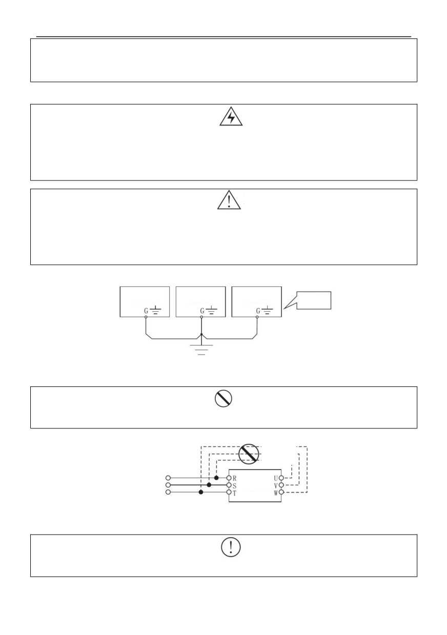
● For the sake of safety, the grounding terminals of inverters must be grounded reliably. To avoid the influence of
grounding common impedance interference, multiple inverters should be grounded by one-point grounding, as shown in
Figure 1-1.
Inverter
Inverter
Inverter
Correct
grounding
mode
Grounding bus (connected at the same point)
Figure 1-1
Prohibition
● It is forbidden to connect the AC power supply to the output terminals U, V and W of the inverter, otherwise the
inverter will be damaged, as shown in Figure 1-2.
Prohibition
AC
Power
Inverter
Inverter
Figure 1-2
Enforcement
● When it is on the input power supply side of the inverter. Be sure to configure a fuse-free circuit breaker for circuit
protection to prevent the accident from expanding due to the failure of the inverter.
4
Attention
● The electromagnetic contactor should not be installed on the output side of the inverter, because the contactor will
turn on and off when the motor is running, which will produce operating overvoltage and cause damage to the inverter.
However, configuration is still necessary for the following three situations:
The frequency conversion governor used for energy-saving control, the system often works at rated speed, and in
order to realize economic operation, it is necessary to cut off the inverter.
Participate in important process flow, cant shut down for a long time, and need to switch between various control
systems to improve system reliability.
When one inverter controls multiple motors. Users should pay attention to the fact that the contactor must not act
when the inverter has output!
1.5 Use safety matters
Danger
● Do not operate with wet hands.
● For inverters with stored for more than one year, the voltage regulator should be used to gradually increase the
voltage to the rated value when powering on, otherwise there is danger of electric shock and explosion.
●Don’t touch the inside of the inverter after it is powered on, and don’t put bars or other objects into the inverter,
otherwise it will cause electric shock death or the inverter can’t work normally.
●Please do not open the face cover when the inverter is powered on, otherwise there is a danger of electric shock.
● Use the restart function after power failure with caution, otherwise it may cause personal injury or death.
Warning
●If it runs over 50Hz, it is necessary to ensure the speed range of motor bearings and mechanical devices in use.
●Mechanical devices requiring lubrication, such as reduction boxes and gears, should not run at low speed for a long
time, otherwise their service life will be shortened and even equipment will be damaged.
● When the ordinary motor runs at low frequency, it must be derated because of its poor heat dissipation effect. If it is a
constant torque load, it must adopt the forced heat dissipation mode of motor or adopt a special frequency conversion
motor.
● Please cut off the input power of the inverter when it is not used for a long time, so as to avoid the inverter being
damaged or even causing fire due to foreign matter entering or other reasons.
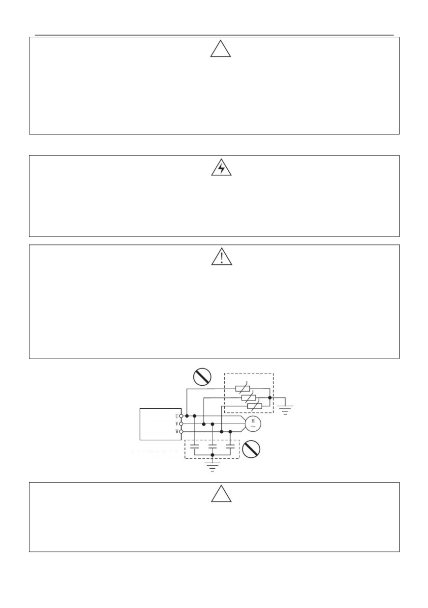
● Since the output voltage of the inverter is PWM pulse wave, please do not install capacitors or surge current
absorbers (such as piezoresistors) at its output end, otherwise the inverter will fail and trip, and even the power
components will be damaged. If installed, be sure to remove it. As shown in figure 1 -3.
Pro
hibit
Surge current absorber
ion
Inverter
Prohibition
Power factor compensation capacitor
Figure 1-3
Attention
● Before the motor is used for the first time or placed for a long time before reuse, the motor insulation shall be
checked and the measured insulation resistance shall be ensured to be no less than 5MΩ.
● If you need to use the inverter outside the allowable working voltage range, you need to configure a step-up or
step-down device for transformation processing.
● In the area where the altitude exceeds 1,000 meters, the heat dissipation effect of the inverter will deteriorate due to
the thin air, so it needs to be derated. Generally, it needs to be derated by about 10% for every 1000m increase.
5
Chapter II Standard Specifications of Products
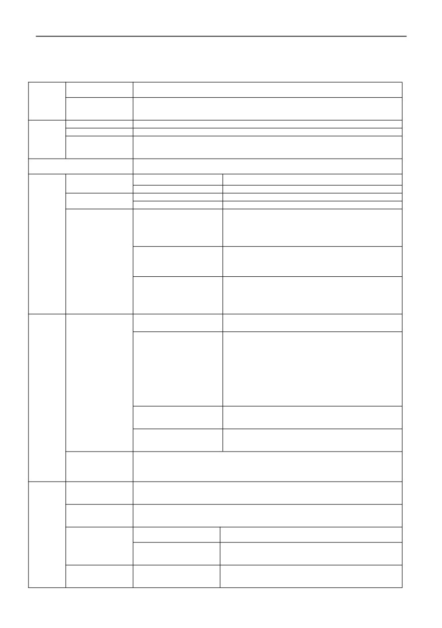
2.1 Technical specifications
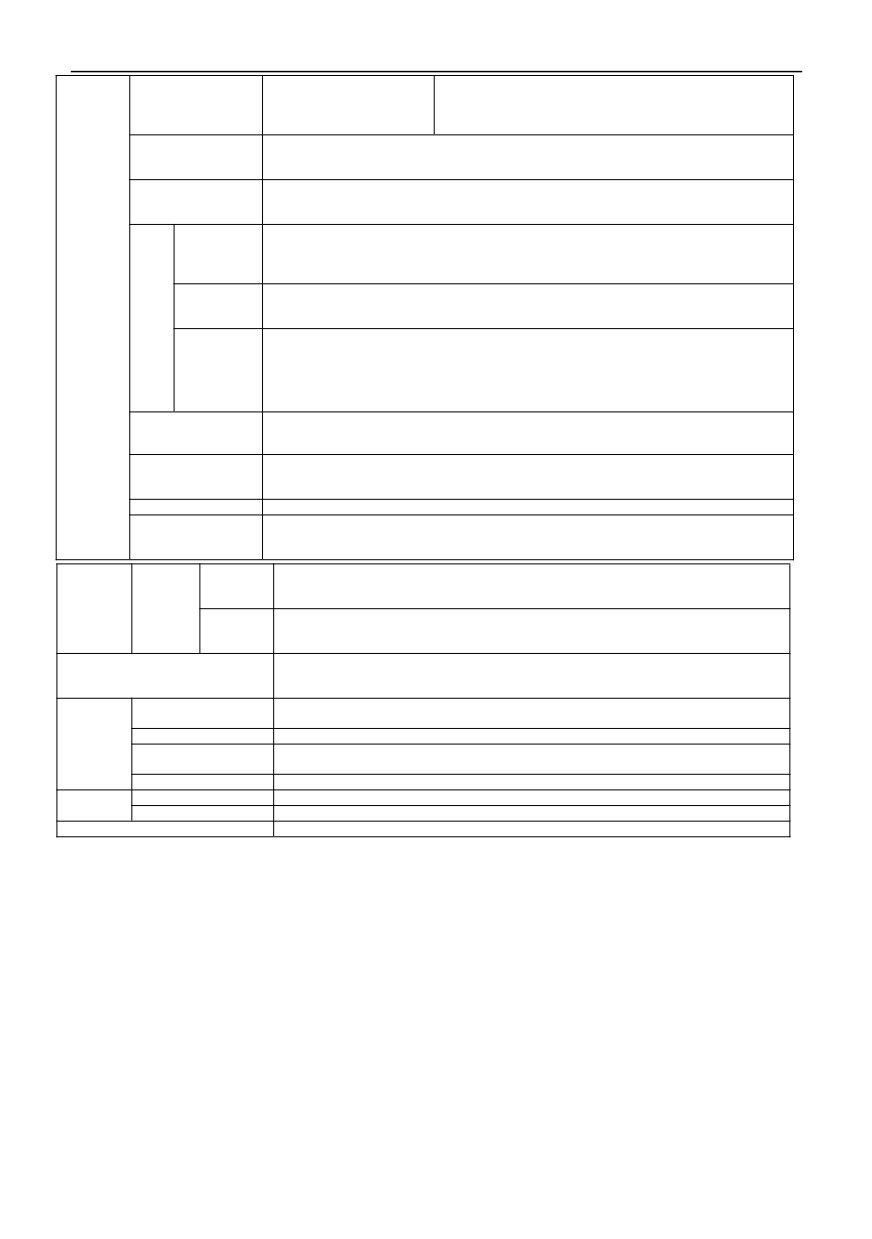
Rating Voltage ,
Three-phase (G3/G4 series) 380V-480V, 50/60HZ
Frequency
Single&Three-phase (G1/G2 series)
220 V: 50/60 Hz
Input
Three-phase (G3 series) : AC 380~440 (-15%~+10%)
Allowable range
Three-phase (G4 series) : AC 460~480 (-15%~+10%)
of voltage
Single&Three-phase (G1/G2 series) : AC220V±15%
Voltage
G1/G2 series; 0~220V, G3 series; 0~440 V, G4 series; 0~480 V
Frequency
Low frequency mode: 0 ~ 300 Hz; high frequency mode: 0 ~ 3000 Hz
Output
G type machine: 110% long-term; 150% 1 minute ;200% 4 seconds
Overload capacity
P type machine: 105% long-term ;120% 1 minute; 150% 1 second
V/F control, advanced V/F control, V/F separation control and PG-free current vector
Control mode
control
Frequency setting
Analog end input
0.1% of the maximum output frequency
Resolution
Digital settings
0.01Hz
Frequency
Analog input
Within 0.2% of the maximum output frequency
accuracy
Digital input
Set the output frequency within 0.01%
The reference frequency can be set arbitrarily from 0.5
Hz to 3000 Hz, and the multi-point V/F curve can be set
V/F curve (voltage
arbitrarily. You can also choose a variety of fixed curves
frequency characteristic)
Control
such as constant torque, torque reduction 1, torque
charact
reduction 2 and square torque
eristic
Manual setting: 0.0 ~ 30.0% of rated output
Automatic boost: automatically determine the boost
V/F control
Torque boost
torque according to the output current and motor
parameters
Whether in acceleration, deceleration or stable
operation, the motor stator current and voltage can be
Automatic current and
automatically detected, which can be suppressed within
voltage limiting
the allowable range according to the unique algorithm
to minimize the possibility of system fault tripping
voltage frequency
Automatically adjust output voltage-frequency ratio
characteristic
according to motor parameters and unique algorithm
Starting torque:
150% rated torque at 3.0Hz (VF control)
150% rated torque at 1.0Hz (advanced VF control)
150% rated torque at 0.5Hz (without PG current vector
control)
Torque characteristic
Running speed steady-state accuracy: ≤± 0.2% rated
Sensorless
vector
synchronous speed
control
Speed fluctuation: ≤± 0.5% rated synchronous speed
Control
Torque response: ≤20ms (without PG current vector
charact
control)
eristic
Without any restriction, the parameters can be
Self-determination of
automatically detected under static and dynamic
motor parameters
conditions to obtain the best control effect
Full-range current closed-loop control, completely
Current and voltage
avoiding current impact, with perfect overcurrent and
suppression
overvoltage suppression function
Especially for users with low grid voltage and frequent fluctuation of grid voltage, the
Running
system can maintain the longest possible operation time according to the unique
undervoltage
algorithm and residual energy allocation strategy even in the range below the
suppression
allowable voltage
Multi speed and
16-stage programmable multi-stage speed control and multiple operation modes are
Swing frequency
optional. Swing frequency operation: preset frequency and center frequency can be
operation
adjusted, and state memory and recovery after power failure
PID control
Built-in PID controller
(preset frequency). Standard configuration RS485
RS485
communication function, multiple communication protocols can be selected, with
communication
linkage synchronous control function
Typical
DC voltage 0 ~ 10 V, DC current 0 ~ 20 mA (upper and
functio
Analog input
lower limits are optional)
n
Frequency setting
keypad setting, RS485
interface setting, UP/DOWN
Digital input
terminal control, and various combination settings with
analog input can also be made.
2
Y-terminal open collector outputs and two
Output signal
Digital output
programmable relay outputs (TA/TB/TC), with up to 61
functions
6
HV100
Series High Performance Current Vector Inverter
2 analog signals are output, and the output range can be
flexibly set between 0 ~ 20mA or 0 ~ 10V, which can
Analog output
realize the output of physical quantities such as set
frequency and output frequency
Automatic voltage
According to the needs, three modes can be selected: dynamic voltage stabilization,
stabilizing
static voltage stabilization and non-voltage stabilization, so as to obtain the most
operation
stable operation effect
Acceleration and
0.1s ~ 3600.0min can be set continuously, and S-type and linear mode can be
deceleration
selected
Time setting
Energy
consumpti
Energy consumption braking starting voltage, return difference voltage and energy
on
consumption braking rate can be continuously adjusted
Brake
Direct
Starting frequency of DC braking during shutdown:
0.00
~ [00.13] upper limit
current
frequency
Bra
Brake
Braking time: 0.0 ~ 100.0 s; Braking current: 0.0% ~ 150.0% rated current
ke
Magnetic
flow
0 ~ 100 0: invalid
Brake
Low noise
The carrier frequency is continuously adjustable from 1.0 kHz to 16.0 kHz to minimize
operation
the noise of the motor
Revolving speed
It can realize the smooth restart and instantaneous stop restart of the motor in
tracking speed
operation
Restart facility
Counter
One internal counter is convenient for system integration
Upper and lower limit frequency setting, frequency jump operation, reverse operation
Operating function
limit, slip frequency compensation, RS485 communication, frequency increment and
decrement control, fault self-recovery operation, etc
Output frequency, output current, output voltage, motor speed, set
Running
frequency, module temperature, PID setting, feedback amount,
State
keypad
analog input and output, etc
Display
display
The last six fault records, the record of six operation parameters such as output
Alarm
frequency, set frequency, output current, output voltage, DC voltage and module
Content
temperature during the last fault trip.
Over-current, over-voltage, under-voltage, module failure, electronic thermal relay,
Protection function
overheating, short circuit, input and output phase failure, abnormal tuning of motor
parameters, internal memory failure, etc.
Ambient
-10℃ ~+40℃ (the ambient temperature is 40℃ ~ 50℃, please use it at a reduced
temperature
level)
Environ
Ambient humidity
5% ~ 95% RH, no water condensation
ment
Surrounding
Indoor (no direct sunlight, corrosion, flammable gas, oil mist, dust, etc.)
environment
Altitude
1000 meters above the use of derating, every 1000 meters up derating 10%
Structu
Protection grade
IP20
re
Cooling mode
Air-cooled with fan control
Installation method
Wall mounted, cabinet mounted
7
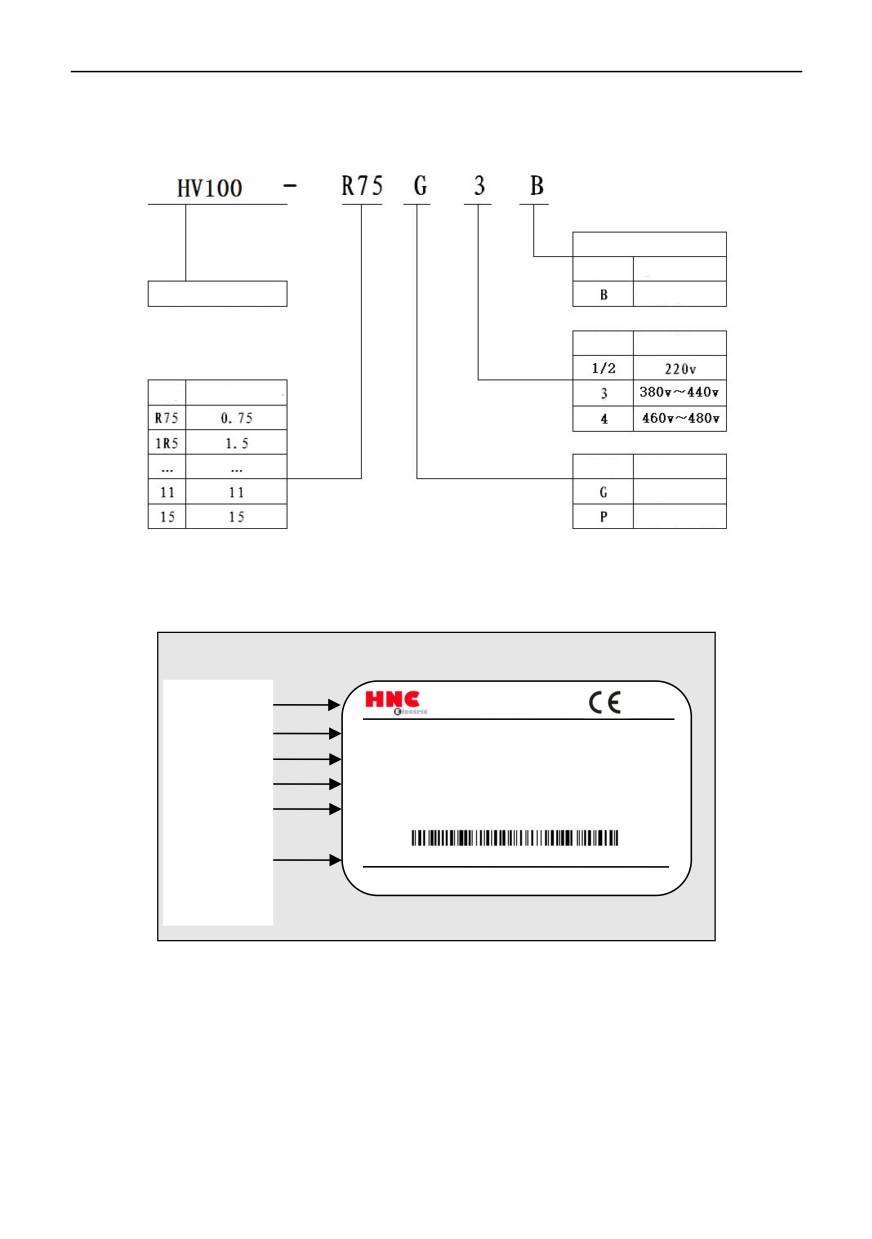
2.2 Inverter model description
2.2.1 Product naming
Brake unit
Empty
No
Inverter series
Built-in
Code
Voltage class
Code
Adaptation motor
power
Code
Type
General
Fan/Pump
type
Figure 2-1 Naming Rules
2.2.2 Nameplate marking
Rated nameplate
Company Logo
Inverter model
MODEL: HV100-004G3
Nominal power
POWER:
4KW
Rated input
INPUT:
3PH AC 380~440V
50Hz/60Hz
Rated output
OUTPUT:
3PH AC 0~440V 8.5A 0~500Hz
Manufacturing code
S/ N:
Serial number
HNC Electric Limited
Figure 2-2 nameplate
8
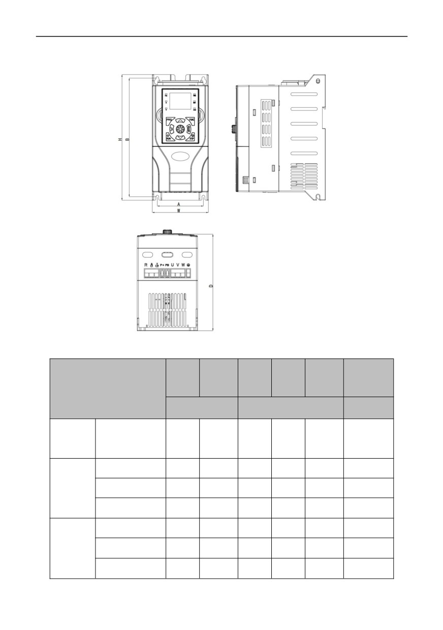
2.3 Size of inverter and keyboard
Figure 2-3 Dimensions of Inverter 0.75KW~30KW
Installation
A
B
H
W
D
hole
(mm)
(mm)
(mm)
(mm)
(mm)
Model No.
(mm)
Mounting
Exterior dimensions
dimension
Single
phase
0.4KW-2.2KW
78
200
212
95
154
5
AC220V
0.4KW-2.2KW
78
200
212
95
154
5
Three
phase
4KW-5.5KW
129
230
240
140
180.5
5
AC220V
7.5KW-15KW
188
305
322
205
199
6
Three
0.75KW-4KW
78
200
212
95
154
5
phase
5.5KW-11KW
129
230
240
140
180.5
5
AC380
~480V
15KW-30KW
188
305
322
205
199
6
9
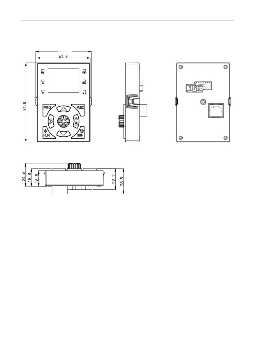
Keyboard dimensions:
10
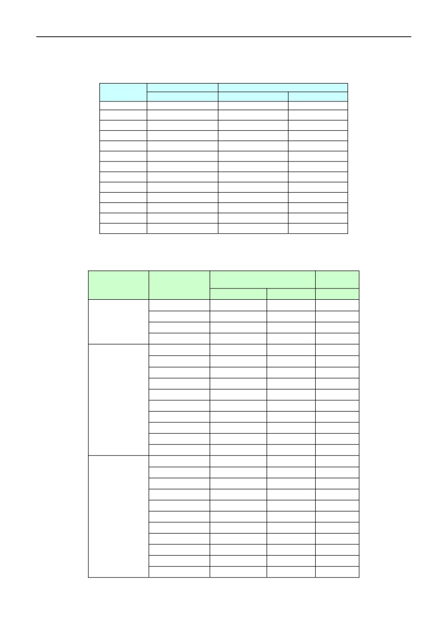
2.4 Rated current output table
Single - phase
Three-phase
Voltage
220V
220V
380~480V
Power(KW)
Current
(A)
Current
(A)
Current
(A)
0.4
2.3
2.1
-
0.75
4
3.8
2.1
1.5
7
7.2
3.8
2.2
9.6
9
5.1
4
-
13
9
5.5
-
25
13
7.5
-
32
17
11
-
45
25
15
-
60
32
18.5
-
-
37
22
-
-
45
30
-
-
60
2.5 Selection of Braking Resistance Table
Braking
Inverter power
Brake resistance specification
Voltage(V)
torque
(KW)
W
Ohm
10%ED
0.4
80
200
125
Single-phase 220
0.75
80
150
125
series
1.5
100
100
125
2.2
100
70
125
0.4
90
300
125
0.75
150
110
125
1.5
250
100
125
2.2
300
65
125
Three-phase 220
4
400
45
125
series
5.5
800
22
125
7.5
1000
16
125
11
2300
12
125
15
3000
9
125
11
2300
12
125
0.75
140
750
125
1.5
300
400
125
2.2
400
250
125
4
750
150
125
5.5
1100
100
125
Three-phase 380~
7.5
1500
75
125
480 series
11
2200
50
125
15
3000
38
125
18.5
4000
32
125
22
4500
27
125
30
6000
20
125
11
Notes:
1. Please select the resistance value specified by our company.
2. Our company will not be liable for any damage to the inverter or other equipment caused by the use of brake resistors
other than those provided by our company.
3. The safety and flammability of the environment must be considered in the installation of the brake resistor, and the
distance from the inverter should be at least 100 mm.
4. The parameters in the table are for reference only, not as standards.
12
Chapter III Storage and Installation
3.1 storage
This product must be placed in a packing box before installation. If it is not used temporarily, please pay attention to
the following items when storing:
● It must be placed in a dry place without dirt;
● The storage environment temperature is within the range of -20℃ to +65℃;
● The relative humidity of the storage environment is in the range of 0% to 95%, and there is no condensation;
● The storage environment contains no corrosive gas or liquid;
● It is best to be placed on a shelf and packaged for storage. It is best not to store the inverter for a long time.
Long-term storage will lead to deterioration of electrolytic capacitor. If long-term storage is required, it must be ensured that
it is electrified once within half a year for at least 5 hours. When inputting, the voltage must be slowly increased to the rated
voltage value by a voltage regulator.
3.2 Installation site and environment
Note: the environmental conditions of the installation site will affect the service life of the inverter. Please install the
inverter in the following places:
● Ambient temperature:-5 ~ 40℃ and good ventilation;
● Places without dripping water and low temperature;
● Places without sunlight, high temperature and serious dust falling;
● Places without corrosive gases and liquids;
● Places with less dust, oil and gas and metal dust;
● Places without vibration and easy to maintain and check;
● Places without electromagnetic noise interference;
3.3 Installation space and direction
● For the convenience of maintenance, enough space should be left around the inverter. As shown in the figure.
● In order to achieve good cooling effect, the inverter must be installed vertically and the air circulation should be
smooth.
●If the installation is not secure. After installing a flat plate under the base of the inverter, it is installed on a loose plane,
and the stress may cause damage to the main circuit parts, thus damaging the inverter;
● The wall of installation shall be made of incombustible materials such as iron plates.
● Multiple inverters are installed in the same cabinet. When installing from top to bottom, pay attention to the spacing,
and add a diversion baffle in the middle or install it in a staggered way.
13
Chapter IV Wiring
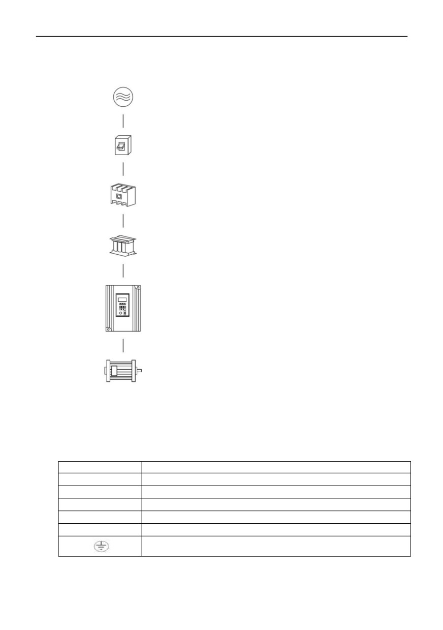
4.1 Main circuit wiring diagram
Power supply: Please pay attention to whether the voltage levels
are consistent, so as not to damage the inverter.
Fuseless switch: please refer to the corresponding table.
Leakage switch: please use leakage switch with high-order
harmonic protection.
Magnetic contactor:
Note: please do not use electromagnetic contactor as the power
switch of frequency converter.
Ac reactor: when the output capacity is greater than 1000KVA, it is
recommended to install an AC reactor to improve the power factor.
Inverter:
Be sure to properly connect the main circuit and control signal line
of the inverter.
Be sure to set the inverter parameters correctly.
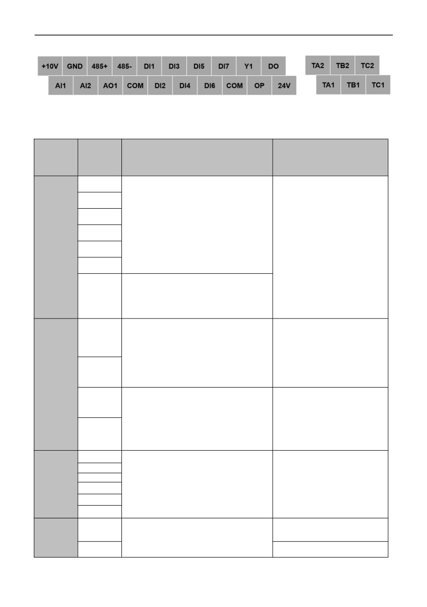
4.2 Connecting terminal Figure
4.2.1 The function description of the main circuit terminal is as follows:
Terminal name
Function description
R、S、T
Three-phase power input Terminal
P+、 P-
External brake unit reserved terminal
P+、PB
External braking resistor reserved terminal (0.75KW~30.0KW)
P+、 P1
Reserved terminal of external DC reactor
U、V、W
Three-phase AC output terminal
Ground terminal
14
4.2.2 The terminal for controlling loop
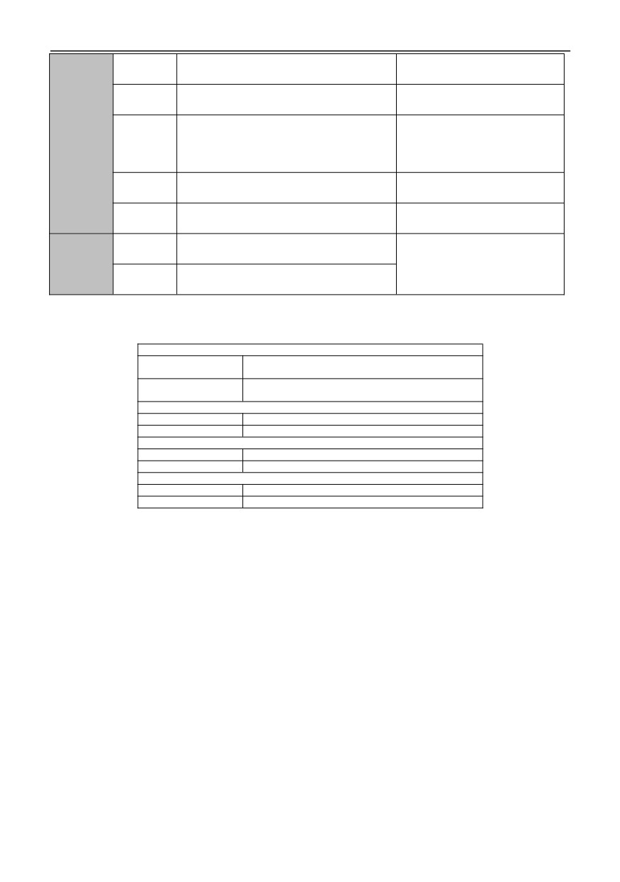
Function description of control circuit terminal
Classifica
Terminal
Description of functions
Specification
tion
label
DI1
DI2
Short circuit between DI(DI1, DI2, DI3, DI4, DI5,
DI3
DI6, HDI) ~ COM is valid, and its functions are
set by parameters 07.00 ~ 07.06 respectively
DI4
Multifuncti
(common terminal: com).
onal digital
Input, 0 ~ 24V level signal, active at
input
DI5
low level, 5mA.
terminal
DI6
HDI can be used as a common multi-function
terminal, and can also be programmed as a
DI7(HDI)
high-speed pulse input port. see 07.06
functional description for details.
AI1 receives analog voltage/current input. The
voltage and current are selected by jumper JP3.
AI1
The factory default input voltage. If the current
INPUT, input voltage range: 0 ~ 10v
is to be input, just adjust the jumper cap to Cin
(input impedance: 100KΩ), input
position. AI2 only receives voltage input. See
current range: 0 ~ 20ma (input
the description of function code 06.01 ~ 06.10
impedance: 500Ω).
Analog
AI2
for the setting of measuring range. (reference
input and
ground: GND)
output
AO1 provides analog voltage/current output,
terminals
which can represent 14 physical quantities.
OUTPUT, 0 ~ 10v DC voltage.
AO1
The output voltage and current are selected by
Output voltages of AO1 and AO2
jumper JP4, and the factory default output
terminals are PWM waveforms
voltage. If you want to output current, just jump
from the central processing unit.
AO2
the jumper cap to Co1 position. See description
The output voltage is proportional
(Reserved)
of function codes 06.21 and 06.22 for details.
to the width of PWM waveform.
(reference ground: GND)
TA1
TA1-TB1 and TA2-TB2 are
normally closed;
TB1
TA1-TC1 and TA2-TC2 are
Relay
TC1
Programmable relay output terminals are
normally open.
output
defined as multi-functions, with 62 types. See
TA2
Contact capacity: 250vac/2a (cos ф
terminal
07.20 and 07.21 for details.
= 1);
TB2
250VAC/1A(COSФ=0.4),30VDC/1
TC2
A.
1. Switching capacity: 50mA/30V
Open
HDO
Programmable defined as multifunctional
2. Output frequency range:
Collector
collector output terminals, up to 62 kinds. See
0~50kHz
output
07.18 and 07.19 for details.
1. Switching capacity: 50mA/30V
terminal
Y1
2. Output frequency range: 0~1kHz
15
+24V is the circuit common power supply of
+24V
Maximum output current 200mA
digital signal input terminal
+10V is the circuit common power supply of
+10V
Maximum output current 20mA
analog input and output terminals
The factory default is OP connected to +24V.
When using external signals to drive DI1~DI6,
DC power
OP
OP needs to be connected to the external
External power input terminal
supply
power supply and disconnected from the +24V
power supply terminal
Digital signal and +24V power supply reference
COM
Internally isolated from GND
ground
Analog signal and +10V power supply reference
GND
Isolated internally from COM
ground
485+
RS485+
Standard RS485 communication
Communic
interface is not isolated from GND.
ation
Please use twisted pair or shielded
interface
485-
RS485-
wire.
4.2.3 Jumper settings of main control board
JP2
Represents 485 communication terminal resistance
OFF
is not connected
Represents 485 communication terminal resistance
ON
is connected
JP3
Cin
Represents AI1 input current signal, 4-20mA
Vin
Represents AI1 input voltage signal, 0-10V
JP4
Vo1
Represents AO1 output voltage signal, 0-10V
Co1
Represents AO1 output current signal, 4-20mA
JP5
Vo2(Reserved)
Represents AO2 output voltage signal, 0-10V
Co2(Reserved)
Represents AO2 output current signal, 4-20mA
4.3 Basic wiring diagram
Inverter wiring is divided into main circuit and control circuit. The user can lift the cover of the shell, and the main circuit
terminal and the control circuit terminal can be seen at this time. The user must connect accurately according to the
following wiring circuits.
16
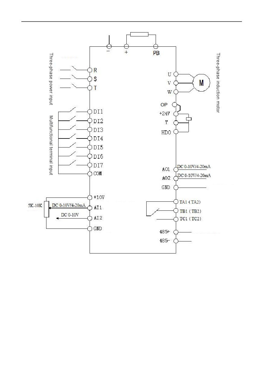
Braking resistance
Circuit breaker
Default
Open collector output 1
Open collector output 2
(Reserved)
For the selection of
Relay R1
voltage and
Relay R2
Potentiometer
current signals,
refer to jumpers on
the previous page
R485 Communication
Basic operation wiring diagram
4.4 Matters needing attention for Wiring
4.4.1 Main circuit wiring
●When wiring , please implement wiring in accordance with the provisions of electrical laws and regulations to ensure
safety.
● For power supply wiring, please use isolation wire or line pipe, and ground both ends of the isolation layer or line
pipe;
● Please install an air circuit breaker NPB between the power supply and the input terminals (R, S, T). (If using the
leakage circuit breaker, please use the circuit breaker with high frequency countermeasures).
● Please arrange the power line and control line separately, and do not place them in the same trunking.
● Do not connect the AC power supply to the inverter output terminals (U, V, W);
● The output wiring must not touch the metal part of the inverter housing, otherwise it may cause a short circuit to the
ground.
● Components such as phase-shifting capacitors, LC and RC noise filters cannot be used at the output end of inverter.
● The main circuit wiring of inverter must be far away from other control equipment.
17
● When the wiring between the inverter and the motor exceeds 50m (220V series) and 100m (380V class), high dv/dt
will be generated in the coil of the motor, which will damage the interlayer insulation of the motor. Please use the AC motor
dedicated to the inverter or install a reactor on the inverter side.
● When the distance between the inverter and the motor is long, please reduce the carrier frequency, because the
larger the carrier, the greater the leakage current of higher harmonic on the cable, which will have adverse effects on the
inverter and other equipment.
4.4.2 Control circuit wiring (signal line)
The signal line should not be placed in the same slot as the main circuit wiring, otherwise interference may occur.
Please use shielded wires for signal wires, and ground them at one end. The wire diameter is 0.5-2mm² 1 shielded wire is
recommended for the control line. Use the control terminals on the control keypadcorrectly as required.
4.4.3 Grounding wire
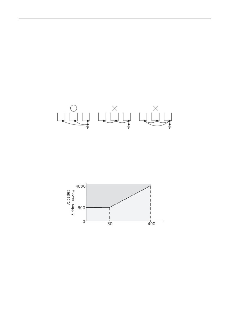
Please use the third grounding method (below 100Ω) to ground the grounding wire terminal E; Please use the
grounding wire according to the technical basic length and size of electrical equipment; Never share the grounding
electrode with large power equipment such as electric welding machine and power machinery, and the grounding wire
should be as far away from the power line of large power equipment as possible; Please use the grounding wiring mode of
multiple inverters in the following figure (a) to avoid the loop of (b) or (c).
● Grounding wiring must be as short as possible.
●Please properly ground the grounding terminal E, and never connect to the zero line.
(a) Correct
(b) Error
(c) Error
4.5 Matters needing attention for specific application
4.5.1 Type selection
(1) Installation of reactor
When the inverter is connected to a large-capacity power transformer (above 600kVA) or the phase-advancing
capacitor is switched, the power input circuit will produce excessive peak current, which may damage the components of
the converter. To prevent this, please install DC reactor or AC reactor. This also helps to improve the power factor on the
power supply side. In addition, when thyristor converters such as DC drivers are connected to the same power supply
system, DC reactors or AC reactors must be set regardless of power supply conditions.
Power - tuned reactor is
required
No reactor required
Inverter Capacity (KVA)
Installation conditions of reactor
(2) Inverter capacity
When running a special motor, please make sure that the rated current of the motor is not higher than the rated output
current of the inverter. In addition, when running multiple induction motors in parallel with a inverter, the capacity of the
inverter should be selected so that 1.1 times of the total rated current of the motors is less than the rated output current of
the inverter.
(3) Starting torque
The starting and accelerating characteristics of the motor driven by inverter are limited by the overload rated current of
the combined inverter. Compared with the starting of general commercial power supply, the torque characteristic is smaller.
If a large starting torque is required, please increase the capacity of the inverter by one level or increase the capacity of the
motor and inverter at the same time.
(4) Emergency stop
Although the protection function will act and the output will stop when the inverter fails, the motor cannot be stopped
suddenly at this time. Therefore, please set mechanical stop and hold structure on the mechanical equipment that needs
emergency stop.
18
(5) Special options
Terminals PB(+) and P1(+) are terminals for connecting with special optional items. Do not connect machines other
than special options.
(6) Precautions related to reciprocating load
When the inverter is used for reciprocating loads (cranes, elevators, punching machines, washing machines, etc.), if
150% or more of the current flows repeatedly, the service life of IGBT inside the inverter will be shortened due to thermal
fatigue. As a general standard, when the carrier frequency is 4kHz and the peak current is 150%, the starting/stopping
times are about 8 million times.
Especially when low noise is not required, please reduce the carrier frequency. In addition, please reduce the peak
current during reciprocating to less than 150% by reducing the load, prolonging the acceleration and deceleration time, or
increasing the capacity of the inverter by one level (during the trial run for these purposes, please confirm the peak current
during reciprocating and adjust it as needed). In addition, when used in cranes, it is suggested to make the following
choices to ensure the motor torque and reduce the current of the inverter, because the starting/stopping action during JOG
is fast. · The capacity of the inverter should ensure that its peak current is lower than 150%. The capacity of inverter should
be more than 1 level larger than that of motor.
4.5.2
Matters needing attention in motor use
(1) It is used for existing standard motors
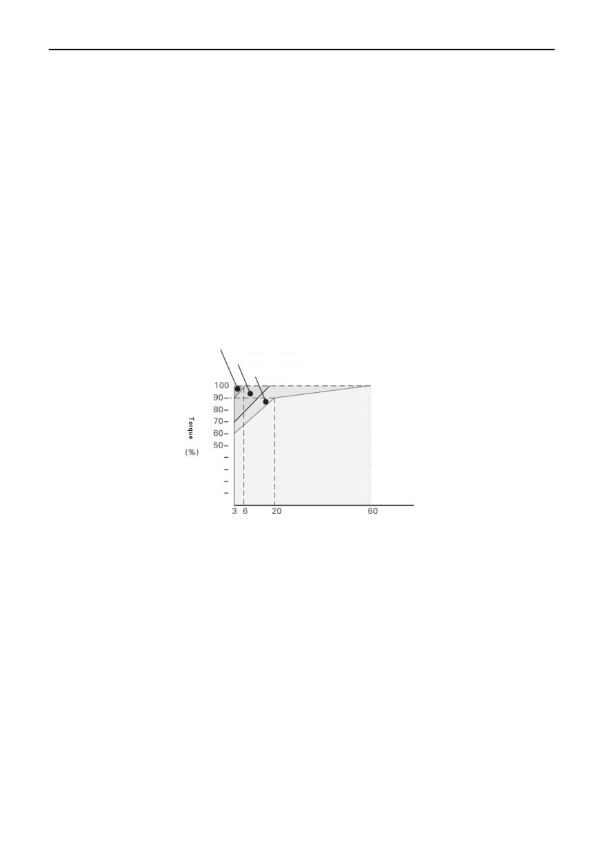
Low speed domain
Compared with the standard motor driven by commercial power supply, the loss caused by using inverter will increase
somewhat. In the low speed range, the cooling effect will deteriorate and the temperature of the motor will increase.
Therefore, in the low speed range, please reduce the load torque of motor. The allowable load characteristics of our
standard motor are shown in the figure. In addition, when 100% continuous torque is required in low speed range, please
discuss whether to use the special motor for inverter.
25%ED (or 15 minutes)
40%ED (or 20 minutes)
60%ED (or 40 minutes)
Continuous
Frequency (Hz)
Allowable load characteristics of our standard motor
(2) Matters needing attention for special motors
The rated current of the pole-changing motor is different from that of the standard motor. Please confirm the maximum
current of the motor and select the corresponding inverter. Be sure to switch the number of poles after the motor stops. If
switching is performed during rotation, the regeneration overvoltage or overcurrent protection circuit will act and the free
running of the motor will stop.
Motor with brake
When using inverter to drive motor with brake, if the brake circuit is directly connected to the output side of inverter, the
brake will not open due to the low voltage during starting. Please use the motor with brake with independent brake power
supply, and connect the brake power supply to the power supply side of the inverter. In general, when using a motor with a
brake, the noise in the low speed range may become larger.
(3) Power transmission structure (reducer, belt, chain, etc.)
When the gearbox, gearbox and reducer with oil lubrication mode are used in the power transmission system, the oil
lubrication effect will become worse if they only run continuously in the low speed range, so please pay attention. In
addition, when running at high speed above 60Hz, problems such as noise of power transmission structure, service life,
strength caused by centrifugal force, etc. will occur, so please pay full attention to it.
19
//////////////////////