HV100 Series Frequency Inverter. User Manual (V4.0) - page 4
Selection of auxiliary frequency source B
00.05
0 ~ 11 (same as main frequency channel selection)
3
0: digital setting 1 (press keyboard key
, encoder+00.10)
1: digital setting 2(UP/DOWN terminal adjustment)
2: digital setting 3 (communication setting)
3: AI1 analog setting (0 ~ 10V/20mA)
4: AI2 analog setting (0 ~ 10V)
5: Pulse setting (0 ~ 50 kHz)
6:Simple PLC
7:Multi-speed settings
8: PID control
9: Keyboard potentiometer setting(compatible encoder)
10:MPPT given(solar water pump)
11: Keyboard potentiometer
All meanings of auxiliary frequency given channel are the same as those of main frequency given channel, please
refer to 00.04 for detailed description.
Frequency source given way
00.06
0~9
0
0: main frequency source A
1:A+K*B
The main frequency, given channel a frequency, and the auxiliary frequency, given channel b frequency, are multiplied
by the weight coefficient k, and then the two frequencies are added as the final given frequency of the inverter.
2:A-K*B
The main frequency, given channel A frequency, and the auxiliary frequency, given channel B frequency, are
multiplied by the weight coefficient k, and then the two frequencies are subtracted as the final given frequency of the
inverter.
3:︱A-K*B︱
The main frequency, given channel A frequency, and the auxiliary frequency, given channel B frequency, are
multiplied by the coefficient k, and then the two frequencies are subtracted as the final given frequency of the inverter.
4:MAX(A,K*B)
After multiplying the given channel A frequency of the main frequency and the given channel B frequency of the
auxiliary frequency by the weight coefficient K, compare the two frequencies and take the larger one as the final given
frequency of the inverter.
5:MIN(A,K*B)
After multiplying the given channel A frequency of the main frequency and the given channel B frequency of the
auxiliary frequency by the weight coefficient K, compare the two frequencies, and take the smaller one as the final given
frequency of the inverter.
6: switch A to K*B
This function is used in conjunction with the 29th function item of DI1~HDI function in F7 group parameters. When
00.06 =6 and the function of X terminal is selected as 29, the X terminal is valid and the given frequency source is switched
from A to K * B; X terminal is invalid, the frequency source returns to a ..
7: Switch between A and (A+K*B)
This function is used in conjunction with function item No.30 of terminal DI1 ~ X8 function in F7 group parameters.
When 00.06=7 and X terminal function is selected as 30, the X terminal is valid and the frequency given source is switched
from A to (A+K * B); When the X terminal is invalid, the frequency source returns to A.
8: Switch between A and ( A-K * B)
This function is used in conjunction with function item No.31 of terminal DI1 ~ x8 function in F7 group parameters.
When 00.06=8 and X terminal function is selected as 31, the X terminal is valid and the frequency given source is switched
from A to (A-K * B); When the X terminal is invalid, the frequency source returns to A.
Notes:
The given frequency is still limited by the starting frequency, upper and lower frequencies, etc. The positive and
negative frequency determines the running direction of the inverter.
Where K is the weight coefficient of auxiliary frequency source b, please refer to the detailed description of 00.11
function code for specific settings.
Digital setting 1
00.07
0000~1111
0000
LED single digit: power down store
0: store
60
When the inverter is powered on, the panel frequency increment is initialized to the value saved in EEPROM during the
last power failure.
1:not store
When the inverter is powered on, the panel frequency increment is initialized to 0.
LED 10-digit: stop keep
0: keep
When the inverter stops, the frequency set value is the final modified value.
1: Stop not keep
When the inverter stops, the set frequency is restored to 00.09.
LED 100-digit:
key、Negative frequency adjustment
0: invalid
1: valid
When the selection is valid, the positive and negative adjustment of frequency can be realized by operating keyboard
keys.
Digital setting 2
00.08
0000~1111
0000
LED single digit: power down store
0:store
When the inverter is powered on, the terminal frequency increment is initialized to the value saved in EEPROM during
the last power failure.
1:not store
When the inverter is powered on, the terminal frequency increment is initialized to 0.
LED 10-digit: stop keep
0: keep
When the inverter stops, the frequency set value is the final modified value.
1: Stop not keep When the inverter is not stopped, the set frequency is restored to 00.10.
LED 100-digit: UP/DOWN negative frequency regulation
0: invalid
1: valid
Select valid, terminal UP/DOWN can realize the positive and negative adjustment of frequency.
Frequency source digital given 1 setting
00.09
0.00Hz~【00.13】upper limit frequency
50.00
When the frequency channel is defined as digital given 1 (the main frequency source is 0 and the auxiliary frequency
source is 0), this function parameter is the initial set frequency given by the digital frequency of the inverter panel.
Frequency source digital given 2 setting
00.10
0.00Hz~【00.13】upper limit frequency
50.00
When the frequency channel is defined as digital given 2 (the main frequency source and auxiliary frequency source are
1), this function parameter is the initial set frequency of the frequency given by the inverter terminal.
Setting of auxiliary frequency source weight coefficient K
00.11
0.01~10.00
1.00
K is the weight coefficient of auxiliary frequency source
Max output frequency
00.12
Low frequency band: max {50.00, [00.13]} ~ 300.00; high frequency band: max
50.00
{50.0, [00.13]} ~ 300.0
Upper limit frequency
00.13
【00.14】~【00.12】
50.00
Lower limit frequency
00.14
0.00Hz~【00.13】
0.00
61
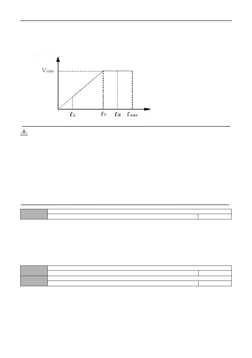
The maximum output frequency is the highest frequency allowed by the inverter, which is the benchmark for setting
acceleration and deceleration time, as shown in the figure fmax below. The basic operating frequency is the minimum
frequency corresponding to the highest voltage output by the inverter, which is generally the rated frequency of the motor,
as shown in the figure below. The maximum output voltage Vmax is the corresponding output voltage when the inverter
outputs the basic operating frequency, which is generally the rated voltage of the motor; Vmax;as shown in the following
figure; FH and FL are defined as upper limit frequency and lower limit frequency respectively, as shown in Figure 00-1:
Output voltage
Output frequency
Figure 00-1 Schematic diagram of voltage and frequency
Notes:
1. The maximum output frequency, upper limit frequency and lower limit frequency should be carefully set according to the
nameplate parameters and operating conditions of the actual controlled motor, otherwise the equipment may be damaged.
2. The limit range of upper frequency is valid for JOG operation, while the limit range of lower frequency is invalid for JOG
operation.
3. In addition to the upper limit frequency and the lower limit frequency, the output frequency of the inverter during
operation is also limited by the set values of parameters such as starting frequency, starting frequency of DC braking during
shutdown and jumping frequency.
4. The relationship among maximum output frequency, upper limit frequency and lower limit frequency is shown in the
above figure 00-1. Please pay attention to the order of magnitude when setting.
5. The upper and lower limit frequencies are used to limit the actual output frequency of the motor. If the set frequency is
higher than the upper limit frequency, it will run at the upper limit frequency; Run at the lower limit frequency if the set
frequency is lower than the lower limit frequency (the running state when the set frequency is lower than the lower limit
frequency is also related to the setting of function code 01.31); If the set frequency is less than the starting frequency, it will
run at zero frequency when starting.
Frequency output mode
00.15
0000~011
0000
LED single digit: high and low frequency mode selection
0: Low frequency mode (0.00~300.00HZ)
1: High frequency mode (0.0~300.0HZ)
LED 10-digit: acceleration and deceleration reference selection
0: Maximum output frequency as the reference
1: Target output frequency as the reference
LED 100-digit: reserved
LED 1000-digit: reserved
The high frequency mode is only effective for V/F control
Acceleration time 1
00.16
0.1~3600.0S
Model setting
Deceleration time 1
00.17
0.1~3600.0S
Model setting
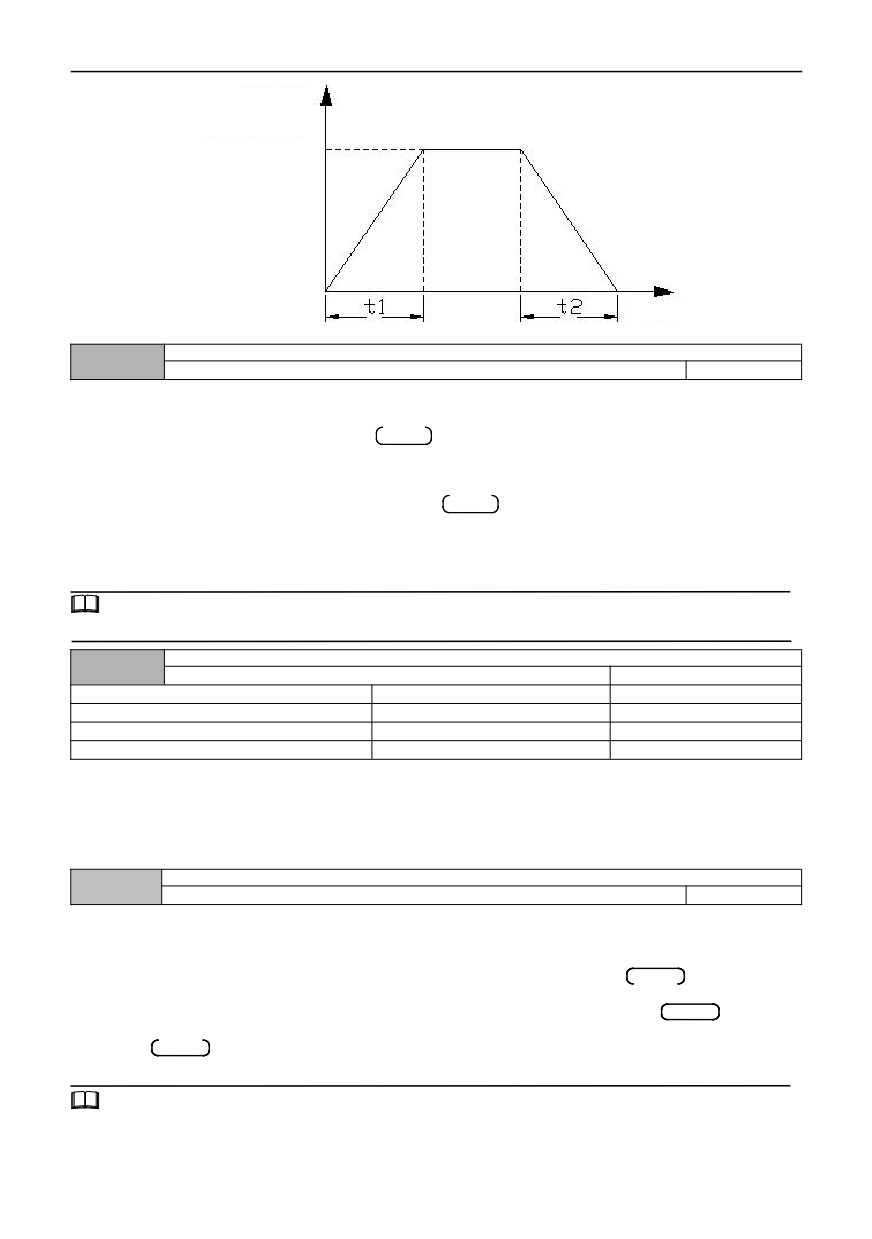
The acceleration time refers to the time required for the inverter to accelerate from zero frequency to the maximum
output frequency, as shown in the figure below at t1. Deceleration time refers to the time required for the inverter to
decelerate from the maximum output frequency to zero frequency, t2 as shown in the figure below.
There are four groups of acceleration and deceleration time parameters of this series of inverters, and the acceleration and
deceleration time of the other three groups is defined in the function codes 01.13 ~ 01.18. The factory default acceleration
and deceleration time is determined by the model. If you want to select other acceleration and deceleration time groups,
please select them through the multi-function terminal (please refer to the function codes 07.00 ~ 07.06). The acceleration
and deceleration time of JOG operation are defined separately in 01.22 and 01.23.
62
Output frequency
Max output frequency
Time
Figure 00-2 Schematic diagram of acceleration time and deceleration time
Running direction setting
00.18
0~2
0
0: Forward direction
When this mode is selected, the actual output phase sequence of the inverter is consistent with the default phase
sequence of the system. At this time, the keys RUN
on the panel and FWD terminal functions become forward
control.
1: Reverse direction
When this mode is selected, the actual output phase sequence of the inverter will be opposite to the default phase
sequence of the system. At this time, the functions of keys RUN
and FWD terminals on the panel are changed to
reverse control.
2. Forbidden reverse operation
In any case, the motor can only run forward. This function is suitable for situations where reverse operation may bring
danger or property loss. Given the reverse command, the inverter runs at zero speed.
Tips:
This function code setting is valid for running direction control of all running command channels.
Carrier frequency setting
00.19
1.0~16.0KHz
Model setting
0.4~4.0KW
6.0KHz
1.0~16.0KHz
5.5~30KW
4.5KHz
1.0~16.0KHz
37~132KW
3.0KHz
1.0~10.0KHz
160~630KW
1.8KHz
1.0~5.0 KHz
This function code is used to set the carrier frequency of PWM wave output by inverter. The carrier frequency will affect
the noise when the motor is running, and the carrier frequency can be appropriately increased to meet the requirements
when silent operation is required. However, increasing the carrier frequency will increase the calorific value of the inverter
and the electromagnetic interference to the outside world.
When the carrier frequency exceeds the factory set value, the inverter needs to be derated. Generally, the inverter
current needs to be derated by about 5% for every 1KHz increase of download wave.
User password
00.20
0~65535
0
The user password setting function is used to prohibit unauthorized personnel from consulting and modifying function
parameters.
In order to avoid misoperation, user passwords less than 10 are invalid.
When setting the user password, enter any number not less than 10, press the keyENTER to confirm, and the
password will take effect automatically after 3 minutes.
When you need to change the password, select the 00.20 function code, press the keyENTER
to enter the
password verification state, enter the modification state after the password verification is successful, enter a new password,
press the keyENTER
to confirm, and the password will automatically take effect after 3 minutes.
Please keep your password properly. If you forget it, please ask the manufacturer for service.
Tips:
Please keep the password, and consult the manufacturer if it is lost.
63
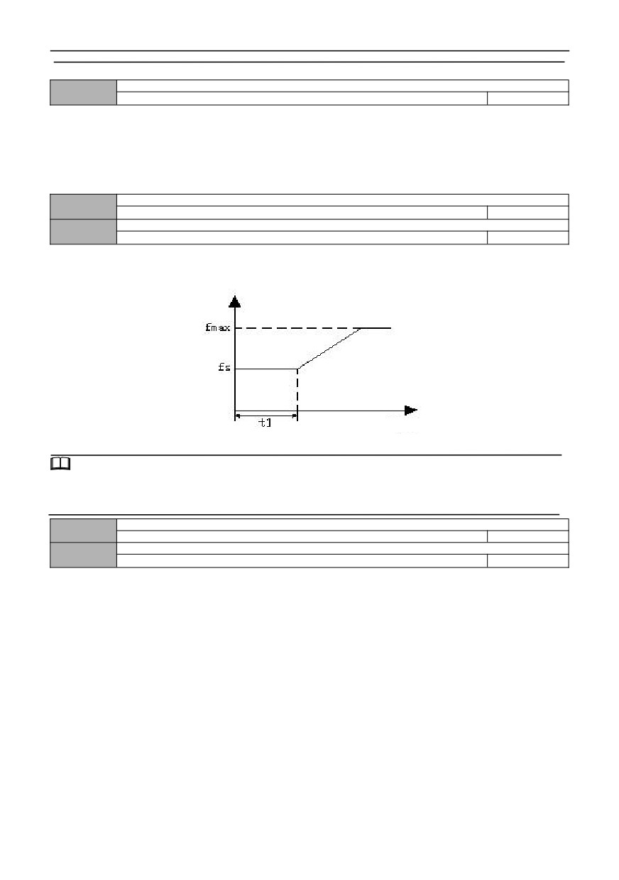
Group 01-start-stop control parameters
Starting mode
01.00
0~2
0
0: Starting frequency starting
Start according to the set starting frequency (01.01 ) and starting frequency holding time (01.02 ).
1: DC braking+starting frequency starting
First DC brake (refer to 01.03 and 01.04), and then start according to mode 0.
2. Speed tracking starting
In case of power-on after power failure, if the starting conditions are met, the inverter will automatically start running in
the mode of speed tracking after waiting for the time defined in 12.15.
Starting frequency
01.01
0.00~50.00Hz
1.00
Starting frequency holding time
01.02
0.0~600.0s
0.0
Starting frequency refers to the initial frequency when the inverter starts. As shown in the figure fs below, for some
systems with large starting torque, setting reasonable starting frequency can validly overcome the problem of starting
difficulty. The starting frequency holding time refers to the time that the inverter keeps running at the starting frequency
during the starting process, as shown in the figure below at t1. Schematic diagram of startup frequency is as follows:
Time
Figure 01-1 Diagram of Start Frequency
Tips:
1、The start frequency is not limited by the lower limit frequency. The JOG frequency is not limited by the lower limit
frequency but is limited by the starting frequency.
2. When 00.15=1 (high frequency mode), the upper limit of starting frequency is 500.0Hz.
Starting DC braking current
01.03
0.0 ~ 150.0% * rated current of motor
0.0%
Starting DC braking time
01.04
0.0~100.0s
0.0
The starting DC braking current is set as a percentage relative to the rated output current of the inverter.
When starting DC braking time is 0.0s, there is no DC braking process. As shown in the figure below:
64
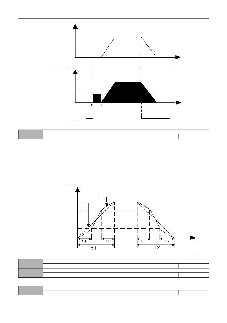
Output Frequency
Time
Current output
(effective values)
DC braking
capacity
DC braking time
Time
Run Command
Figure 01-2 Diagram of starting DC brake
Acceleration / deceleration mode
01.05
0~1
0
0: Straight line acceleration / deceleration
The relationship between output frequency and time increases or decreases according to a constant slope, as shown
in the following figure.
1: S-curve acceleration / deceleration
The relationship between output frequency and time increases or decreases according to the S-shaped curve. When
acceleration starts and speed arrives, and when deceleration starts and speed arrives, the speed set value is in the
S-shaped curve state. This can make acceleration and deceleration smooth and reduce the impact on the load. S-curve
acceleration and deceleration mode is suitable for the start and stop of transporting and transferring loads, such as
elevators and conveyor belts. As shown in the figure below: t1 is acceleration time, t2 is deceleration time, ts is start time of
S curve, te is end time of S curve, 01.06=ts/t1,01.07=te/t2.
Output
Frequency
Curve
Straight-line
Running
time
Figure 01-3 Schematic diagram of acceleration and deceleration of straight line and S curve
Time proportion at the beginning of S curve
01.06
10.0~50.0%
20.0%
Time proportion at the end of S curve
01.07
10.0~50.0%
20.0%
See the S-curve acceleration and deceleration term in 01.05.
Stop mode
01.08
0~1
0
0: deceleration to stop
65
After receiving the shutdown command, the inverter gradually reduces the output frequency according to the
deceleration time, and stops after the frequency drops to zero. If the shutdown DC braking function is valid, the DC braking
process will be executed after reaching the shutdown DC braking start frequency (according to 01.09 setting, a shutdown
DC braking waiting time may be required), and then the shutdown will be performed.
1: Free stop
After receiving the shutdown command, the inverter immediately terminates the output, and the load stops freely
according to the mechanical inertia.
Start frequency of DC braking during stop
01.09
0.00 ~ [00.13] upper limit frequency
0.00
Waiting time for DC braking during stop
01.10
0.0~100.0s
0.0
DC braking current during stop
01.11
0.0 ~ 150.0% * rated current of motor
0.0%
Time for DC braking during stop
01.12
0.0: DC brake does not operate
0.0
0.1~100.0s
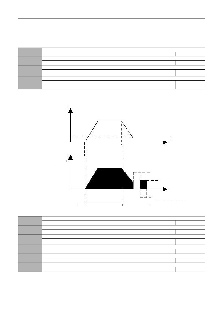
The set value of DC braking current during shutdown is a percentage relative to the rated current of the inverter. When
the stop braking time is 0.0s, there is no DC braking process. As shown in the figure below:
Output
Frequency
Stop braking start
frequency
Output current
(effective)
Stop braking waiting time
DC braking capacity
Stop braking time
Run Command
Figure 01-4 Diagram of shutdown DC brake
Acceleration time 2
01.13
0.1~3600.0
Type setting
Deceleration time 2
01.14
0.1~3600.0
Type setting
Acceleration time 3
01.15
0.1~3600.0
Type setting
Deceleration time 3
01.16
0.1~3600.0
Type setting
Acceleration time 4
01.17
0.1~3600.0
Type setting
Deceleration time 4
01.18
0.1~3600.0
Type setting
Four groups of acceleration and deceleration time can be defined and can be controlled by different groups of terminals
To select the acceleration and deceleration time 1 ~ 4 during the operation of the inverter, please refer to the definition of
the terminal function of increasing deceleration time 07.00 ~ 07.06.
66
Tips:
Acceleration and deceleration time 1 is defined in 00.16 and 00.17.
Selection of acceleration and deceleration time unit
01.19
0~2
0
0: Second
1: Minute
2:0.1 second
This function code defines the dimension of acceleration and deceleration time.
Jog forward running frequency setting
01.20
0.00 ~ [00.13] upper limit frequency
5.00
Jog reverse running frequency setting
01.21
0.00 ~ [00.13] upper limit frequency
5.00
Jog acceleration time
01.22
0.1~3600.0s
Type setting
Jog deceleration time
01.23
0.1~3600.0s
Type setting
Jog Interval time
01.24
0.1~100.0s
0.1
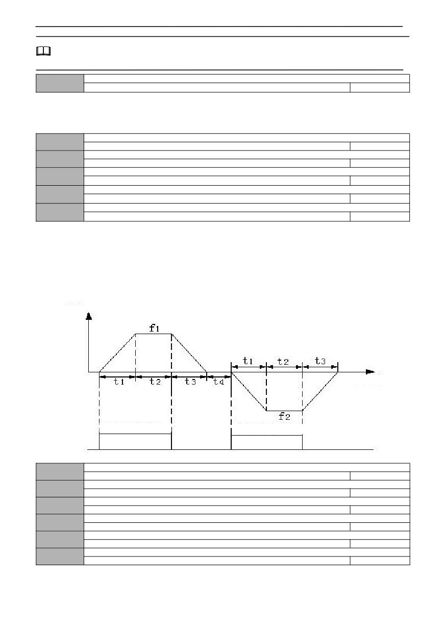
01.20 ~ 01.24 defines relevant parameters during jog operation. As shown in fig. 01-5, t1 and t3 are the actual jog
acceleration and deceleration time; t2 is JOG time; t4 is jog interval time (01.24); 01 is the running frequency of forward jog
(01.20); f2 is the reverse jog operation frequency (01.21). The actual jog acceleration time t1 is determined according to the
following formula:
t1=01.20*01.22/00.12
Similarly, the actual jog deceleration time t3 can be determined as follows:
t3=01.21*01.23/00.12
Where 00.12 is the maximum output frequency.
Output
Time
Forward jog command
Reverse jog command
Figure 01-5 JOG Operation Diagram
Jump frequency 1
01.25
0.00 ~ upper limit frequency
0.00
Jump frequency 1 range
01.26
0.00 ~ upper limit frequency
0.00
Jump frequency 2
01.27
0.00 ~ upper limit frequency
0.00
Jump frequency 2 range
01.28
0.00 ~ upper limit frequency
0.00
Jump frequency 3
01.29
0.00 ~ upper limit frequency
0.00
Jump frequency 3 range
01.30
0.00 ~ upper limit frequency
0.00
67
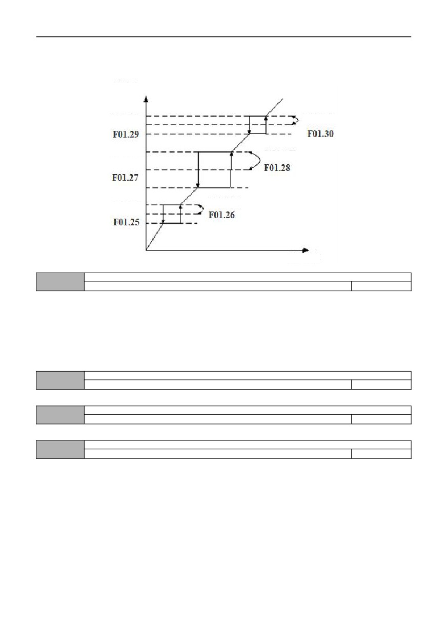
The above function codes are functions set to make the output frequency of inverter avoid the resonance frequency
point of mechanical load. The set frequency of the inverter can be given by jumping near some frequency points according
to the following figure. Its specific meaning is that the frequency of the inverter will never run stably within the jumping
frequency range, but will pass through this range during acceleration and deceleration.
Set frequency
after jump
Jump Frequency
Jump range
Jump range
Jump Frequency
Jump range
Jump Frequency
Set frequency
Figure 01-6 Diagram of Jump Frequency
Action when the set frequency is lower than the lower limit frequency
01.31
0~2
0
0: Run at the lower limit frequency.
When the set frequency is lower than the set value of the lower limit frequency (00.14), the inverter operates at the
lower limit frequency.
1: Zero frequency operation after delay time
When the set frequency is lower than the set value of the lower limit frequency (00.14), the inverter runs at zero
frequency after a delay time (01.32).
2: Shutdown after a delay time
When the set frequency is lower than the set value of the lower limit frequency (00.14), the inverter stops after a delay
time (01.32).
Stop delay time when frequency is lower than lower limit frequency (simple dormancy)
01.32
0.0~3600.0s
10.0
See 01.31 parameter description for details.
Zero frequency braking current
01.33
0.0~150.0%
0.0
This parameter is the percentage of the rated current of the motor.
Forward and reverse dead zone time
01.34
0.0~100.0s
0.0
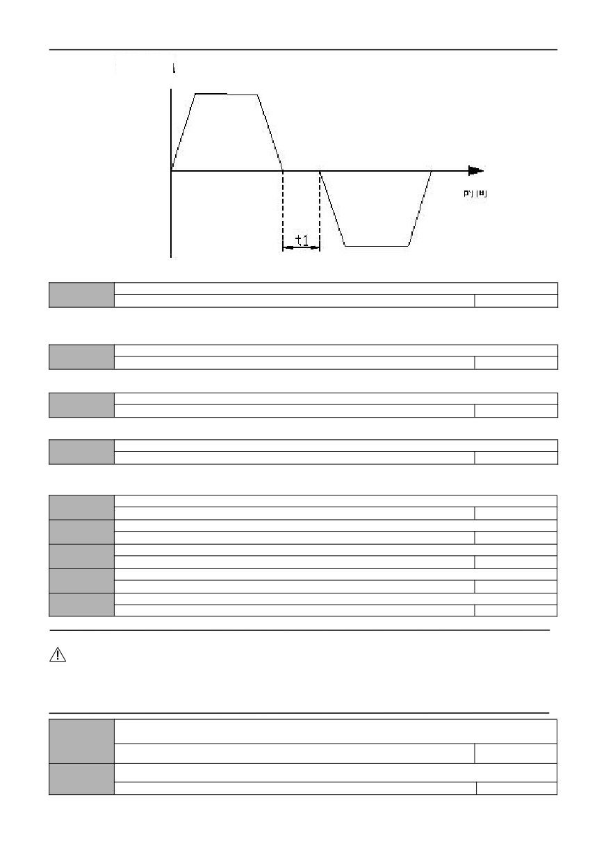
The waiting time for the inverter to transition from forward operation to reverse operation, or from reverse operation to
forward operation, as shown in the t1 figure below. The waiting frequency of switching transition is also related to the
setting of 01.35.
68
Output
frequency
Time
Figure 01-7 Schematic diagram of forward and reverse dead time
Forward and reverse switching mode
01.35
0~1
0
0: Over 0Hz frequency switching
1: Over start frequency switching
Emergency stop standby deceleration time
01.36
0.1~3600.0S
1.0
For details, please refer to the function description of No. 10 in the digital input terminal (07.00~07.06).
Current holding time for DC braking during shutdown
01.37
0.0~100.0S
0.0
002 Group- Motor parameters
Selection of motor type
02.00
0~1
0
0: AC asynchronous motor
1: reserved
Motor rated Power
02.01
0.4~999.9KW
Model setting
Motor rated frequency
02.02
0.01Hz~【00.12】Max output frequency
50.00
Motor rated speed
02.03
0~60000RPM
Model setting
Motor rated voltage
02.04
0~999V
Model setting
Motor rated current
02.05
0.1~6553.5A
Model setting
Notes:
The above function codes must be set according to the motor nameplate parameters. Please configure the
corresponding motor according to the power of the inverter. If the power difference is too large, the control performance of
the inverter will obviously decrease.
Stator resistance of asynchronous motor
02.06
0.01~20.000Ω
Model setting
Rotor resistance of asynchronous motor
02.07
0.01~20.000Ω
Model setting
69
Inductance of stator and rotor of asynchronous motor
02.08
0.1~6553.5mH
Model setting
Mutual inductance between stator and rotor of asynchronous motor
02.09
0.1~6553.5mH
Model setting
No-load current of asynchronous motor
02.10
0.01~655.35A
Model setting
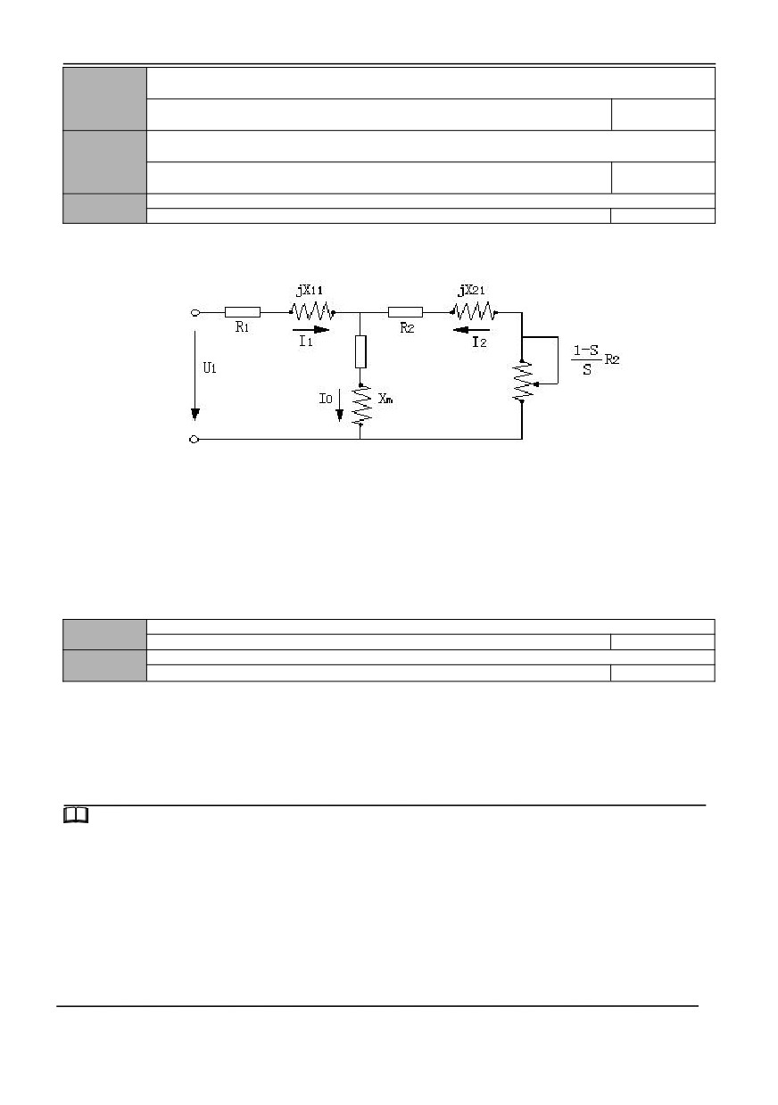
The specific meanings of the above motor parameters are shown in Figure F2-1.
Fig. F2-1 steady-state equivalent circuit diagram of asynchronous motor
R1, jx11, R2, jxI21, Xm and Io in Figure F2-1 respectively represent stator resistance, stator leakage inductance, rotor
resistance, rotor leakage inductance, mutual inductance and no-load current.
If the motor is tuned, the set values from 02.06 to 02.10 will be updated after the tuning is finished.
After the rated power of asynchronous motor is changed to 02.01, the parameters from
02.03 to
02.10 are
automatically updated to the default parameters of asynchronous motor with corresponding power (02.02 is the rated
frequency of motor, which is not within the range of default parameters of asynchronous motor and needs to be set by the
user according to the nameplate).
02.11~
Reserved
02.15
Reserved
0
Motor tuning selection
02.16
0~3
0
0: No action
1. Static tuning
Parameter measurement mode when the motor is in a static state, which is suitable for situations where the motor and
the load cannot be separated.
2. No-load Complete tuning
The complete parameter measurement mode of the motor is adopted as far as possible when the motor can be
separated from the load.
Tips:
1:When 02.16 is set to 2, if there is over current and tuning fault during tuning, It is necessary to check whether the output
is out of phase and whether the models match
2:When 02.16 is set to 2, When complete tuning is carried out, the motor shaft should be separated from the load, and the
complete tuning of the motor with load is prohibited;
3:Before starting the motor parameter tuning, make sure that the motor is in a stopped state, otherwise the tuning cannot
be performed normally.
4:In some occasions (such as the motor can not be separated from the load, etc.), when complete tuning is inconvenient or
the user has low requirements for motor control performance, static tuning can be performed.
5:If tuning is impossible and the user already knows the accurate motor parameters, the user can directly input the motor
nameplate parameters (02.01 ~ 02.14), and the superior performance of the inverter can still be exerted. The tuning is
unsuccessful, protect the action and display E-21.
70
Pre-excitation holding time of asynchronous motor
0.00~10.00S
0.4 ~4.0KW
0.02S
02.17
5.5~30KW
0.05S
Model setting
37~132KW
0.10S
160~630KW
0.20S
Note: This parameter is invalid for VF control
003 group- Reserved
004 group-Speed loop and torque control parameters
Speed loop (ASR1) proportional gain
04.00
0.000~6.000
1.000
Speed loop(ASR1) Integral time
04.01
0.000~32.000S
1.000
ASR1 filter time constant
04.02
0.000~0.100S
0.000
Switch low point frequency
04.03
0.00Hz~【04.07】
5.00
Speed loop (ASR2) proportional gain
04.04
0~6.000
1.500
Speed loop(ASR2) Integral time
04.05
0.00~32.000S
0.500
ASR2 filter time constant
04.06
0.000~0.100S
0.000
Switch high point frequency
04.07
04.03 ~ [00.13] upper limit frequency
10.00
Function codes 04.00 ~ 04.07 are valid without PG vector control.
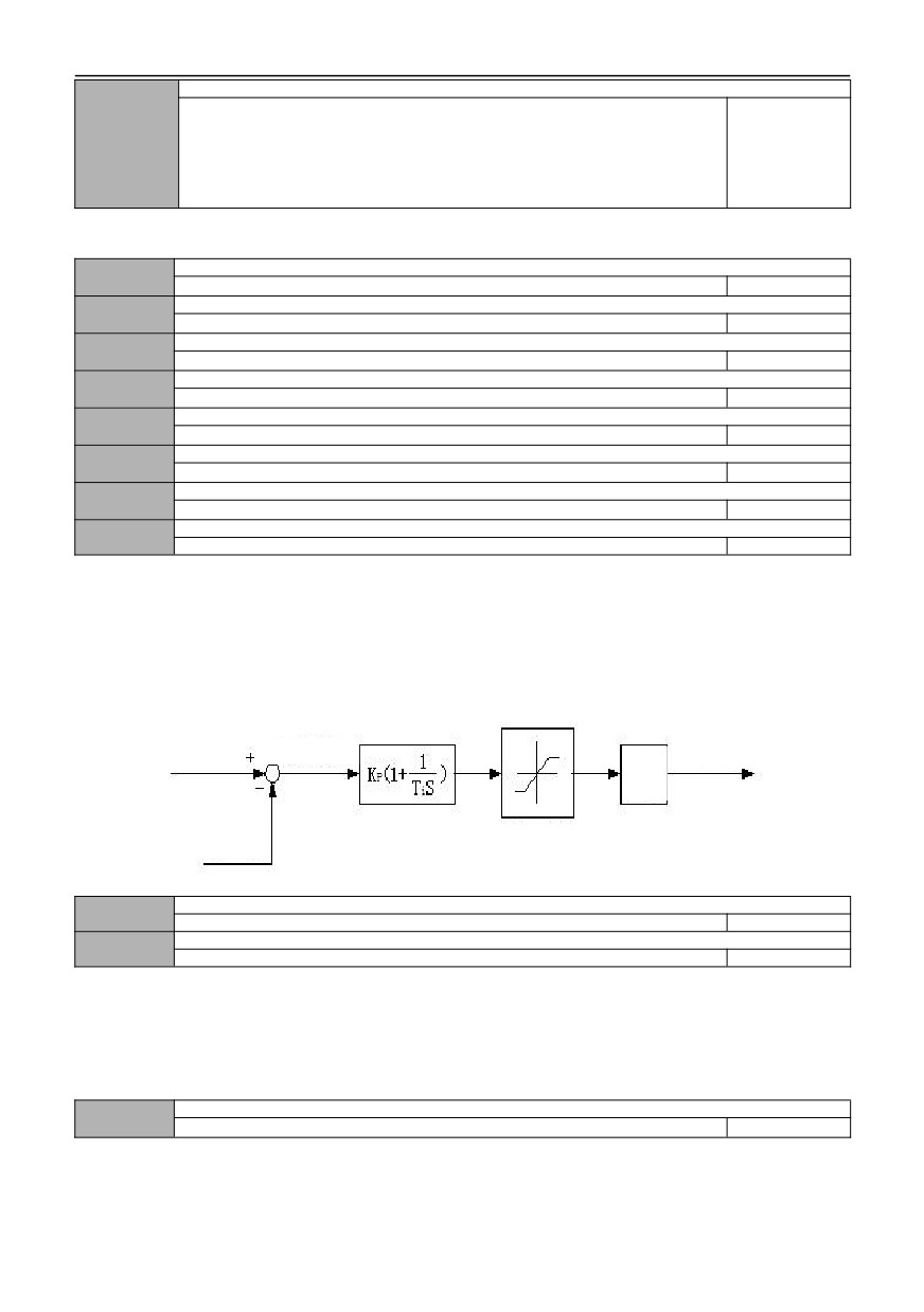
In vector control mode, the speed response characteristics of vector control are changed by setting the proportional
gain p and integration time i of the speed regulator.
The composition of the speed regulator (ASR) is shown in Figure F4-1. In the figure, KP is the proportional gain P, TI
is the integral time I ..
Frequency
(speed) command
Torque
current
Speed error
given +
Output
filter
Actual
Torque limit
speed
Fig. F4 -1 simplified diagram of speed regulator
Positive slip compensation coefficient of vector control (electric state)
04.08
50.0% ~ 200.0% * rated slip frequency
100.0%
Negative slip compensation coefficient of vector control (braking state)
04.09
50.0% ~ 200.0% * rated slip frequency
100.0%
Under the vector control mode, the above function code parameters are used to adjust the speed stability accuracy of
the motor. When the motor is under heavy load and the speed is low, increase this parameter, otherwise decrease this
parameter.
The positive slip coefficient compensates the speed when the motor slip is positive, whereas the negative slip
coefficient compensates the speed when the motor slip is negative.
Selection of speed and torque control
04.10
0~2
0
0: Speed
When there is no PG current vector control, the control object is speed control.
1:Torque
Torque control is the control object without PG current vector control. Please refer to 04.12 ~ 04.24 for related
parameter settings.
71
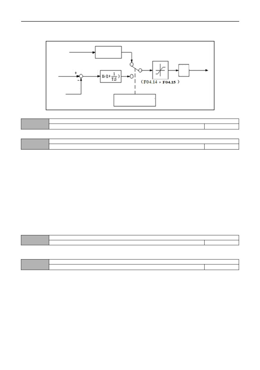
2. Condition effective(terminal switching)
The control object without PG current vector control is controlled by the switch input terminal (DI) defined as speed and
torque control switching. Please refer to function description No.48 of 07 parameter group, DI terminal function.
The external
torque command Primary delay
filtering
Torque
current
Speed Limit
Speed
Outpu
given
Value
Error
t filter
Actual
Speed
Actual Speed (Speed
Limit Value)
Fig. F4-2 simplified block diagram of torque control
Speed and torque switching delay
04.11
0.01~1.00S
0.05
This function code defines the delay time when switching torque and speed mode.
Torque command selection
04.12
0~3
0
This function code sets the torque given channel during torque control.
0:Keypad digit given
Torque commands are given by keypad digit. See 04.13 settings for setting values.
1:AI1
Torque command is set by analog input AI1. The positive and negative input of AI1 corresponds to the
torque
command value in the positive and negative directions.
When using this function, users need to set the physical quantity corresponding to AI1 input as torque instruction, and
also set the corresponding curve of AI1 and the filtering time of AI1 input. Please refer to the description of function code
06.00 ~ 06.05.
2:AI2
Torque command is set by analog input AI1. The positive and negative input of AI1 corresponds to the torque
command value in the positive and negative directions.
When using this function, users need to set the physical quantity corresponding to AI1 input as torque instruction, and
also set the corresponding curve of AI1 and the filtering time of AI1 input. Please refer to the description of function code
06.06 ~ 06.11.
3: Communication given
Torque instruction is given by RS485 communication.
Keyboard digital setting torque
04.13
-200.0% ~ 200.0% * rated current of motor
0.0%
The set value of this function code corresponds to the torque instruction, and is selected as the torque set value given
by keypad digit.
Speed limit channel selection 1 for torque control mode (forward direction)
04.14
0~2
0
This function code sets the forward speed limit channel during torque control.
0:Keypad digit given 1
See 04.16 Settings for details.
1:AI1
The forward speed limiting channel in torque control is given by AI1. Please refer to the description of function code
06.00 ~ 06.05.
2:AI2
The forward speed limiting channel during torque control is given by AI2. Please refer to the description of function
code 06.06 ~ 06.11.
72
Speed limit channel selection 2 of torque control mode (reverse direction)
04.15
0~2
0
This function code sets the reverse speed limit channel during torque control.
0:Keypad digit given 2
See 04.17 Settings for details.
1:AI1
The reverse speed limit channel for torque control is given by AI1. Please refer to the description of function code
06.00 ~ 06.05.
2:AI2
The reverse speed limit channel for torque control is given by AI2. Please refer to the description of function code
06.06 ~ 06.11.
Keyboard numbers limit speed 1
04.16
0.0 ~ 100.0% * [00.12] maximum frequency
100.0%
Keyboard numerals limit speed 1 to a limit relative to the maximum output frequency. This function code corresponds
to the limit value of forward speed when 04.14=0.
Keyboard digital limit speed 2
04.17
0.0 ~ 100.0% * [00.12] maximum frequency
100.0%
Keyboard digital limit speed 2 to a limit relative to the maximum output frequency. This function code corresponds to
the limit value of reverse speed when 04.15=0.
Torque rise time
04.18
0.0S~10.0S
0.1
Torque fall time
04.19
0.0S~10.0S
0.1
Torque rise/fall time defines the time when the torque rises from 0 to the maximum value or falls from the maximum
value to 0.
Electric torque limitation in vector mode
04.20
G type: 0.0% ~ 200.0% * motor rated current 180.0%
Model setting
P type: 0.0% ~ 200.0% * rated current of motor 120.0%
Brake torque limitation in vector mode
04.21
G type: 0.0% ~ 200.0% * rated current of motor 180.0% P type: 0.0% ~ 200.0% *
Model setting
rated current of motor 120.0%
The above function code defines the magnitude of torque limit value when vector control is performed
Torque detection action selection
04.22
0~8
0
Torque detection level
04.23
G type: 0.0% ~ 200.0% * rated current of motor 150.0% P type: 0.0% ~ 200.0% *
rated current of motor 110.0%
Model setting
Torque detection time
04.24
0.0~10.0S
0.0
When the actual torque is within 04.24 (torque detection time) and continuously exceeds 04.23 (torque check level),
the inverter will make corresponding actions according to the setting of 04.22. When the set value of torque detection level
is 100%, it corresponds to the rated torque of the motor.
0: Detection invalid
Torque detection is not performed.
1: Continue to run after detecting torque at constant speed
Over-torque is detected only in the constant speed operation process, and after the torque is detected, the inverter
continues to run.
2: Continue to run after detecting torque during operation
After the torque is detected in the whole operation process, the inverter continues to run.
3: Cut off the output after the torque is detected at constant speed
Over-torque is detected only in the constant speed operation process, and after the torque is detected, the inverter
stops output, and the motor slides to stop freely.
4: Cut off the output after detecting torque in operation
After the torque is detected in the whole running process, the inverter stops outputting and the motor slides and stops
freely.
73
5: Continue running after insufficient torque is detected at constant speed
Insufficient torque is detected only in the constant speed operation process, and after the detection of insufficient
torque, the inverter continues to run.
6: Continue to run after insufficient torque is detected during operation
Insufficient torque is detected in the whole operation process, and the inverter continues to run.
7: Cut off the output after detecting insufficient torque at constant speed
Only in the process of constant speed operation, whether the torque is insufficient is detected, and after the insufficient
torque is detected, the inverter stops outputting, and the motor slides and stops freely.
8: Cut off the output after detecting insufficient torque during operation
After insufficient torque is detected in the whole running process, the inverter stops outputting and the motor slides and
stops freely.
Cutoff frequency of static friction coefficient
04.25
0.00~300.00Hz
10.00
Setting of static friction coefficient
04.26
0.0~200.0
0.0
Static friction coefficient maintenance time
04.27
0.00~600.00s
0.0
As the starting torque of the motor is not enough, increasing the set value of 04.26 can increase the starting torque.
When the speed exceeds the set value of 04.25, the increased torque will slowly decrease to the given torque within the set
time of 04.27.
005 group -VF control parameters
完成情况
V/F curve setting
05.00
0~5
0
This set of function codes defines the V/F curve setting mode of the motor to meet different load characteristic
requirements. According to the definition of 05.00, you can choose five fixed curves and one custom curve.
0: linear curve
The linear curve is suitable for ordinary constant torque load, and the output voltage has a linear relationship with the
output frequency. See straight line 0 in figure F5-1.
1: torque reduction curve 1(1.3 power)
Torque reduction curve 1, the output voltage and output frequency are 1.3 power. See curve 1 in figure F5-1.
2: torque reduction curve 2(1.5 power)
Torque reduction curve 2, the output voltage and output frequency are 1.5 power. See curve 2 in figure F5-1.
3: torque reduction curve 3(1.7 power)
Torque reduction curve 3, the output voltage and output frequency are 1.7 power. See curve 3 in figure F5-1.
4: Square curve
The square curve is suitable for square torque loads such as fans and pumps to achieve the best energy-saving effect,
and the output voltage has a square curve relationship with the output frequency. See curve 4 in figure F5-1.
5: V/F curve set by user (determined from 05.01 to 05.06)
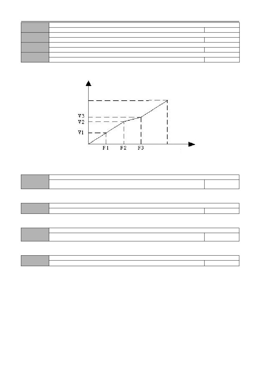
When 05.00 is selected as 5, the user can customize the V/F curve from 05.03 to 05.08, and define the V/F curve by
adding (V1, 01), (V2, F2), (V3, F3) and the polyline of origin and maximum frequency point, which is suitable for special
load characteristics. As shown in figure F5 -1.
74
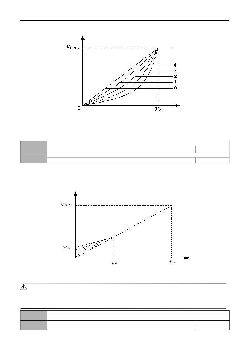
Output
voltage
Output
frequency
Vmax: Maximum output voltage
Fb: Maximum output frequency
Fig. F5-1 V/F curve diagram
Torque boost setting
05.01
0.0 ~ 30.0% rated Voltage of motor
Model setting
Torque boost cutoff frequency
05.02
0.0~ Motor rated Power
15.00
In order to compensate for the low-frequency torque characteristics, some boost compensation can be made for the
output voltage. When this function code is set to 0.0%, it is automatic torque lifting, and when any value is not 0.0%, it is
manual torque lifting mode. 05.02 defines the lifting cut-off frequency point fz when manual torque lifting is performed, as
shown in Figure F5-2.
Vb- manual torque increase
Figure F5-2 Schematic diagram of torque boost
Notes:
1: Under normal V/F control mode, automatic torque boost mode is invalid.
2: Automatic torque boost is only valid in advanced V/F control mode.
V/F frequency value F1
05.03
0.00~ Frequency value F2
12.50
V/F Voltage V1
05.04
0.0 ~ voltage value V2
25.0%
75
V/F frequency value F2
05.05
Frequency value 01 ~ frequency value F3
25.00
V/F Voltage value V2
05.06
Voltage value v1 ~ voltage value V3
50.0%
V/F frequency value F3
05.07
Frequency value F2 ~ rated frequency of motor
37.50
V/F Voltage value V3
05.08
Voltage value v2 ~ 100.0% * rated voltage of motor
75.0%
Schematic diagram of voltage and frequency is as follows:
Voltage
Maximum
output
voltage
Maximum
Frequency
output
frequency
Figure F5-3 Schematic diagram of V/F curve set by users
V/F control slip frequency compensation
05.09
0.0 ~ 200.0% * rated slip
0.0%
The speed of asynchronous motor will decrease after being loaded. Slip compensation can make the speed of motor
close to its synchronous speed, thus making the speed control accuracy of motor higher.
V/F control slip frequency filter coefficient
05.10
1~10
3
This parameter is used to adjust the response speed of slip frequency compensation. The larger the setting of this
value, the slower the response speed and the more stable the motor speed.
V/F control torque frequency compensation filter coefficient
05.11
0~10
Model setting
When the free torque increases, this parameter is used to adjust the response speed of torque compensation. The
larger this value is, the slower the response speed and the more stable the motor speed.
Selection of separate V/F control
05.12
0~3
0
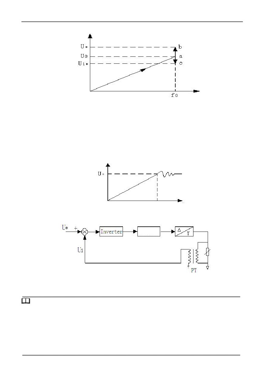
0: VF semi-separated mode, voltage open loop output
In this control mode, the inverter starts according to the normal V/F curve, and then adjusts the voltage to the set target
voltage value after reaching the set frequency point. In this mode, the voltage has no feedback, and the target voltage
value is set as an open loop. As shown in the figure.
76
Output
voltage
Output
frequency
Figure F5-4 Voltage Control Mode 0
F0—— set frequency, V0—— rated voltage corresponding to set frequency, U */U1 * —— set value of a given channel in
05.13.
As shown in the above figure, after the frequency of point A is stabilized, the voltage adjustment begins. According to
the target voltage value and the input voltage, the voltage point may move to point b (increase) or point c (decrease) until it
reaches to the target value.
1: VF semi-separated mode, voltage closed loop output
The only difference between this mode and mode 0 is that it introduces a voltage closed loop, which can stabilize the
voltage by PI adjustment for the deviation between the feedback voltage and the given voltage. It can compensate the
target voltage deviation caused by load change, and make the voltage control precision higher and the response faster, as
shown in the following figure
Output
voltage
Time
Figure F5-5 Voltage Control Mode 1
This control method is widely used in EPS power supply and other fields, and its control principle block diagram is as
follows:
LC Filter
U*—— set value of a given channel in 05.13
U1——analog feedback voltage value (PT)
PT—— Electric quantity transmitter
Figure F5-6 EPS control principle
Tips:
The corresponding relationship between analog feedback channel voltage and actual voltage from 06.06 to 06.11 is
uniquely determined by the voltage transmitter (PT), and its calculation method is as follows:
Assume that U * = 120% * Ue = 456 V (AI1 setting )
PT transformation ratio =50 (input AC 0-500V, output DC 0-10V)
Then when the output reaches to the target voltage of 456V, the feedback voltage of PT output is
456/50V=9.12V
When the upper limit input of AI1 is 10V, the determined input voltage is 500V, and the ratio relative to the rated voltage is
500/380=132%
Therefore, 06.09(AI2 input upper limit voltage) is set to 10.00V, and 06.10(AI2 upper limit corresponding setting) is set to
132%.
77
2: VF fully separated mode, voltage open-loop output
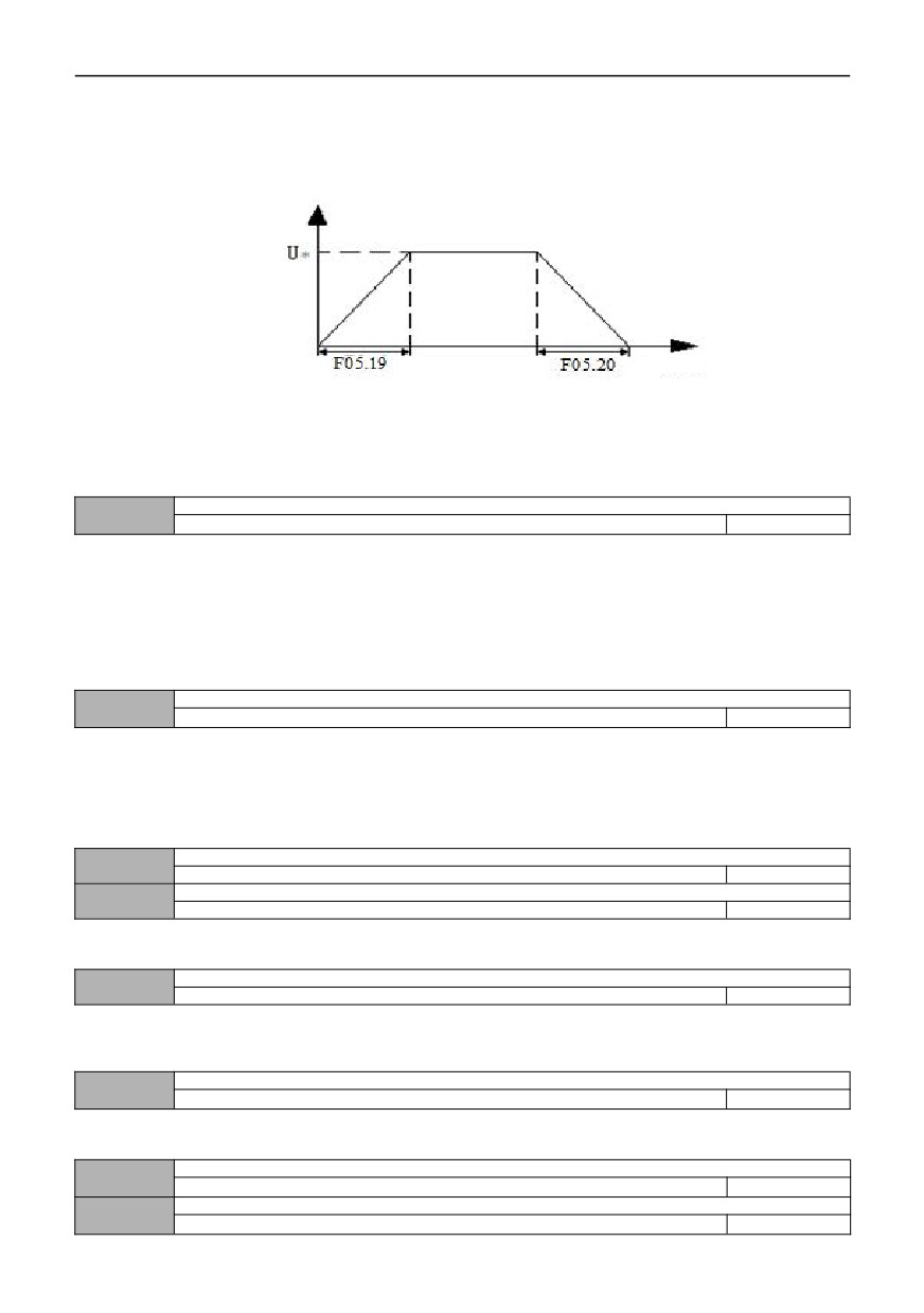
In this mode, the output frequency and voltage of the inverter are completely independent, and the frequency is
accelerate and decelerate according to the defined acceleration and deceleration time, while the voltage is adjusted to the
target value according to the rising/falling time defined by 05.19 and 05.20. As shown in the figure, this control mode is
mainly applied to the design of some variable frequency’s power supplies.
Output
voltage
Time
Figure F5-7 Voltage Control Mode 2
3: VF fully separated mode, voltage closed-loop output
The only difference between this mode and mode 2 is that it introduces a voltage closed loop, which can stabilize the
voltage by PI adjustment for the deviation between the feedback voltage and the given voltage. It can compensate the
target voltage deviation caused by load change, and make the voltage control precision higher and the response faster, as
shown in the following figure
Voltage given channel
05.13
0~2
0
0: Digital given
Set the target voltage value by function code 05.15.
1:AI1
The target voltage value is given by the analog AI1. Pay attention to the physical quantity corresponding to AI1, and
06.00 should be set to 2 (voltage command).
2:AI2
The target voltage value is given by the analog AI2. Pay attention to the physical quantity corresponding to AI2, and
06.00 should be set to 2 (voltage command).
Voltage feedback channel of voltage closed-loop output
05.14
0~1
0
0:AI1
The target voltage value is given by the analog AI1. Pay attention to the physical quantity corresponding to AI1, and
06.00 should be set to 2 (voltage command).
1:AI2
The target voltage value is given by the analog AI2. Pay attention to the physical quantity corresponding to AI2, and
06.00 should be set to 2 (voltage command).
Digitally set the output voltage value
05.15
0.0 ~ 200.0% * rated voltage of motor
100%
Deviation limit of motor closed-loop adjustment
05.16
0.0 ~ 5.0% * rated voltage of motor
2.0%
Used in limited closed loop mode, allow voltage regulate to maximum deviation amplitude, so as to limit the voltage
within a safe range and ensure the reliable running of equipment.
Maximum voltage of VF curve in semi-separated mode
05.17
0.0 ~ 100.0% * rated voltage of motor
80.0%
This function defines the maximum voltage point when starting the equipment according to the voltage and frequency
curve. Reasonable setting of this function can validly prevent the voltage overshoot during starting and ensure the reliable
running of the equipment.
Controller adjustment period of voltage closed-loop output
05.18
0.01~10.00s
0.10
This function code represents the speed of voltage adjustment. If the voltage response is slow, this parameter value can
be appropriately reduced.
Voltage rising time
05.19
0.1~3600.0S
10.0
Voltage drop time
05.20
0.1~3600.0S
10.0
78
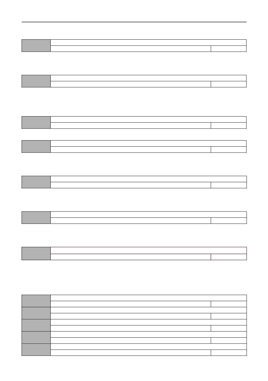
This function code defines the time of voltage rise and fall in the control mode where V and F are completely separated,
that is, mode 2.
Voltage feedback disconnection processing
05.21
0~2
0
0: Alarm and maintain operation with the voltage at the time of disconnection
1: Alarm and reduce the voltage to limiting voltage for operation
2: Protect action and free stop
Voltage feedback disconnection detection value
05.22
0.0 ~ 100.0% * rated voltage of motor
2.0%
The maximum value of the given voltage is taken as the upper limit value of the feedback disconnection detection
value. In the feedback disconnection detection time, when the voltage feedback value is continuously less than the
feedback disconnection detection value, the inverter will make corresponding protection actions according to the setting of
05.21.
Voltage feedback disconnection detection time
05.23
0. 0~100.0s
10.0
Duration before protection action after voltage feedback disconnection.
Limiting voltage of voltage feedback disconnection
05.24
0.0 ~ 100.0% * rated voltage of motor
80.0%
This function code defines the maximum amplitude of the output voltage of the inverter, which means that even if the
protection fails, the final output voltage can also be limited within the allowable safety range when the output feedback is
disconnected and the voltage is continuously raised out of control, thus greatly ensuring the safety of subsequent load
work.
DC Bus undervoltage test value
05.25
0~1000V
0
If the parameter value set 0, the function is invalid. If the DC bus voltage is lower than the parameter value, the system
will report "E-34".
Reset value of DC Bus undervoltage fault
05.26
0~1000V
0
If DC bus voltage is the equals of the parameter value,the system will reset the fault "E-34"and run automatically.
006 group - analog and pulse input and output parameters
AI1 input corresponding physical quantity
06.00
0~2
0
0: Speed command (output frequency,-100.0% ~ 100.0%)
1: Torque command (output torque,-200.0% ~ 200.0%)
AI1 analog setting regards as a given value of torque command, and the given torque range can be -200.0% ~
200.0%. Please refer to F6 group’s detailed function description for related settings.
2: Voltage command (output voltage, 0.0% ~ 200.0% * rated voltage of motor)
AI1 input lower limit
06.01
0.00V/0.00mA~10.00V/20.00mA
0.00
AI1 lower limit corresponds to physical quantity setting
06.02
-200.0% ~ 200.0%
0.0%
AI1 input upper limit
06.03
0.00V/0.00mA~10.00V/20.00mA
10.00
AI1 upper limit corresponds to physical quantity setting
06.04
-200.0% ~ 200.0%
100.0%
AI1 input filter time
06.05
0.00S~10.00S
0.05
79