HV100 Series Frequency Inverter. User Manual (V4.0) - page 8

Appendix
2: Description of macro parameter setting
Functional
Setting
Automatically modify
macro
Commissioning steps
parameters
parameter list
definition
Step1:Initialization of parameter settings
(14.12=2);
Step2: Function macro selection (00.01 = 1);
Step3: Set the sensor range (15.07);
Single pump
00.04=8;08.01=5;14.07=42;
Step4: Determine the feedback type of the sensor,
constant
00.01=1
14.08=40;14.09=42;
and input the voltage feedback signal by default for
pressure water
14.10=40。
AI1 and AI2, or select the input current feedback
supply mode
signal for AI1 through the jumper seat JP3;
Step5: Set the target pressure, which can be set by
parameter 15.08 or by keyboard up and down
keys.
One inverter
Step1:Initialization of parameter settings
with two
(14.12=2);
working (1
Step2:Function macro selection(00.01=2 or 3);
variable
00.03=1;00.04=8;08.01=5;
Step3: Set the sensor range (15.07);
frequency
00.01=2
Step4: Determine the feedback type of the sensor,
pump +2
14.07=42;14.08=40;
and input the voltage feedback signal by default for
power
14.09=42;14.10=40;
AI1 and AI2, or select the input current feedback
frequency
07.00=58;07.01=59;
signal for AI1 through the jumper seat JP3;
pumps) water
07.02=60;07.03=61;
Step5: Set target pressure, which can be set by
supply mode
07.04=62;07.05=63;
parameter 15.08, or by keyboard up and down
Three-pump
07.18=59;07.19=60;
keys;
cycle soft start
07.20=61。
Step6: For details, refer to the description of water
(3 variable
00.01=3
supply parameters for soft start-up of three pumps.
frequency
pumps) water
supply mode
Water supply
00.03=1;00.04=10;
Step1:Initialization of parameter settings
mode of
00.01=4
16.00=0;16.04=0.00;
(14.12=2);
photovoltaic
pump
12.13=80。
Step2:Function macro selection(00.01=4).
Control mode
00.02=2;00.03=1;00.04=3;
Step1:Initialization of parameter settings
of NC machine
00.01=5
00.12=80.00;00.13=80.00;
(14.12=2);
tool
00.16=0.5;00.17=2.0。
Step2:Function macro selection(00.01=5).
00.02=0;00.03=1;
00.16=80.00;01.08=1;
02.03=2950;05.00=5;
Step1:Initialization of parameter settings
Fire patrol
05.01=2.0;05.03=1.25;
(14.12=2);
mode
00.01=6
05.04=2.0;05.05=5.00;
Step2:Function macro selection(00.01=6).
05.06=15.0;05.07=50.00;
05.08=100.0;10.01=120.0;
10.06=200;10.12=180。
Step1:Initialization of parameter settings
EPS power
00.02=4;05.12=0;
00.01=7
(14.12=2);
mode
05.17=100.0;12.19=002.
Step2:Function macro selection(00.01=7).
140
Appendix 3: Parameter description of soft start water supply of three
pump circulation
Function
Name
Setting range
Minimum
Factory
Change
code
unit
setting
0: invalid
2:(1 set of frequency conversion
Multi-pump water
pump +2 sets of power frequency
00.01
1
0
×
supply mode selection
pump)
3:Three pump circulation soft start (3
frequency conversion pumps)
Run command channel
1: terminal operation command
00.03
1
0
×
selection
channel
Main frequency source
00.04
8: PID control setting
1
0
×
selection
07.00
Input terminal DI1
1
58
×
function
07.01
Input terminal DI2
1
59
×
function
33. PID control input
07.02
Input terminal DI3
1
60
×
58: Start/stop (manual)
function
59: Operation allowed
07.03
Input terminal DI4
1
61
×
60: Interlock 1
function
61: Interlock 2
07.04
Input terminal DI5
62: Interlock 3
1
62
×
function
63:PFC start/stop
07.05
Input terminal DI6
1
63
×
function
07.06
Input terminal HDI
1
0
×
function
Open collector output
07.18
1
59
×
terminal Y1 is set
Open collector output
07.19
1
60
×
terminal Y2 setting
59: Interlock 1 output
Output of
60: Interlock 2 Output
07.20
programmable relay
61: Interlock 3 Output
1
61
×
R1
Programmable relay
07.21
1
0
×
R2 output
0: Automatic
Operation input mode
08.00
1: manually input through the defined
1
0
×
of PID
multi-function terminal
0: number given
1:AI1
08.01
PID given channel
2:AI2
1
0
○
selection
3: Pulse given
4: RS485 communication
Given the digital
0.0~100.0%
08.02
0.1%
50.0%
○
quantity setting
0:AI1
1:AI2
2:AI1+ AI2
Selection of PID
3:AI1-AI2
08.03
1
0
○
feedback channel
4:MAX{AI1,AI2}
5:MIN{AI1,AI2}
6: Pulse given
7: RS485 communication
LED bit: PID polarity selection 0:
positive 1: negative
LED ten bits: proportional adjustment
characteristic 0: constant proportional
integral adjustment
1: automatic variable proportion
Advanced
integral adjustment LED hundred bits:
08.04
characteristic setting of
integral adjustment characteristic 0:
1
000
×
PID controller
when the frequency reaches the
upper and lower limits, stop integral
adjustment
1: when the frequency reaches the
upper and lower limits, continue
integral adjustment
LED thousand bits: reservation
141

08.05
Proportional gain KP
0.01~100.00
0.01
1.00
○
08.06
Integration time Ti
0.01~10.00s
0.01s
0.10
○
0.01~10.00s
08.07
Differential time Td
0.0:No derivative
0.01s
0.00
○
0.01~10.00s
08.08
Sampling period T
0.00: Automatic
0.01s
0.10
○
08.09
Deviation limit
0.0~100.0%
0.1%
0.0%
○
Closed loop preset
08.10
0.00 ~ upper limit frequency
0.01Hz
0.00
○
frequency
Preset frequency
08.11
0.0~3600.0s
0.1s
0.0
×
holding time
0: invalid
1: Sleep when feedback pressure
exceeds or falls below sleep
08.12
Sleep mode
1
1
×
threshold
2: Sleep when feedback pressure
and output frequency are stable
Selection of sleep
0: deceleration and shutdown
08.13
1: free stop
1.00
0
○
shutdown mode
Feedback when
0.0~20.0%
entering sleep and
08.14
Note: This function parameter is only
0.1%
5.0%
○
setting the pressure
valid for the second sleep mode
deviation deviation limit
0.0 ~ 200.0% Note: This threshold is
the percentage of the given pressure,
08.15
Sleep threshold
0.1%
100.0%
○
and this function parameter is only
valid for the first sleep mode
0.0 ~ 200.0%
Note:
08.16
Awakening threshold
This threshold is the percentage of
0.1%
90.0%
○
the given pressure
08.17
Sleep delay time
0.0~3600.0s
0.1S
100.0
○
08.18
Wake delay time
0.0~3600.0s
0.1S
5.0
○
Terminal access
15.00
0.0~600.0s
0.1S
0.1
○
disconnection delay
15.01
Polling time
0.0~600.0h
0.1h
48.0
○
Lower limit frequency
15.02
0.0~600.00HZ
0.01HZ
0.00
×
of reducing pump
15.05
Add pump delay time
0.0~3600.0s
0.1S
10.0
○
Reduce pump delay
15.06
0.0~3600.0s
0.1S
10.0
○
time
08.24
Sleep frequency
0.00Hz~ ~ upper limit frequency
0.01HZ
0.00
×
I.
Operating instructions for One inverter with two working and three-pump cycle soft start:
1.
One inverter with two working means that the inverter only starts the first frequency conversion speed regulation,
and the others are directly connected to the power grid.
2.
Three-pump cycle soft start means that each inverter starts, and the power grid is delayed after starting; Start first
shall be connected the grid first, and then the one start later shall be used for speed regulation.
II.
Description of the use of external terminals and the working process of the booster pump:
1.
Input terminal DI1 and ~ DI6 have their functions fixed at the factory.
When 00.01 selects 2 or 3, the input terminals DI1 ~ DI6 fix its water supply function.
2.
Corresponding relationship between X terminal, Y terminal and relay
After DI3 is short-circuited with COM, it corresponds to the output of No.59 interlock 1 in 07.18 ~ 07.21, which is
referred to as No.1 pump for convenience of explanation. After DI4 is shorted to COM, it corresponds to the output of No.60
interlock 2 in 07.18 ~ 07.21, which is referred to as No.2 pump for short; After DI5 is shorted to COM, it corresponds to the
output of No.61 interlock 3 in 07.18 ~ 07.21, which is referred to as No.3 pump for short.
142
3.
Differences between DI1 and DI6
DI1 and DI6 cannot be switched on at the same time. DI1 is manually controlled to start and stop, and only one pump
can be started at a time. The frequency is given by AI1, and PID adjustment is not performed. DI6 controls the start and
stop under the multi-pump water supply mode, and carries out PID adjustment.
4.
Manually control the working process of starting and stopping the pump
After DI1 and COM are short-circuited, the order of pump starting is Start first, start trumpet together. For example,
only after DI5 is connected, only the No.3 pump is turned on; If DI4 and DI5 are connected at the same time, only the No.2
pump will be turned on; If DI3, DI4 and DI5 are connected at the same time, only the No.1 pump will be started.
5.
Working process of multi-pump water supply mode
After DI6 and COM are short-circuited, the order of pump startup is Start first, start smaller power ones together, and
carry out PID control.
(1) When 00.01=2 (one change and two work is valid), if all three pumps are put into operation, after the system is
powered on, first turn on the No.1 pump and start the No.1 variable frequency pump to work. When the working frequency
of No.1 variable frequency pump reaches 50Hz, the pump adding time will be delayed (15.05). If the measured pressure
does not reach the system set pressure, the No.2 power frequency pump will be switched on. When the working frequency
of No.1 variable frequency pump reaches 50Hz again, the No.3 power frequency pump will be switched on if the measured
pressure still does not reach the system set pressure. If the measured pressure is greater than or equal to the set pressure
of the system, the working frequency of No.1 variable frequency pump drops to the lower limit frequency of pump reduction
(15.02 ), and the No.3 power frequency pump will be disconnected after the pump reduction delay (15.06 ). If the measured
pressure is still greater than or equal to the set pressure of the system, and the working frequency of No.1 variable
frequency pump is less than or equal to the lower limit frequency of pump reduction (15.02
(2) When 00.01=3 (three pump circulation is valid), if all three pumps are put into operation, after the system is
powered on, connect pump No. 1 first and start the frequency conversion work of pump No. 1. When the No.1 pump works
at 50Hz, after adding pump delay (15.05), if the measured pressure does not reach the set pressure of the system,
disconnect the No.1 pump, and turn on the No.2 pump and the No.1 power frequency pump. At this time, the No.1 pump
changes from frequency conversion state to power frequency state, and the No.2 pump works in frequency conversion
state. When the No.2 pump works at 50Hz, after adding pump delay (15.05), if the measured pressure still fails to reach the
set pressure of the system, disconnect the No.2 pump, and turn on the No.3 pump and the No.2 power frequency pump. At
this time, the No.2 pump is switched from the variable frequency pump to the power frequency state, while the No.3 pump
is still in the power frequency state. When the working frequency of No.3 pump drops to the lower limit frequency of pump
reduction (15.02 ), after pump reduction delay (15.06 ), if the measured pressure is greater than or equal to the set
pressure of the system, disconnect the No.1 power frequency pump; When the working frequency of No.3 pump is less
than or equal to the lower limit frequency of pump reduction (15.02 ), after the pump reduction delay (15.06 ), if the
measured pressure is still greater than or equal to the set pressure of the system, disconnect the No.2 power frequency
pump; Finally, only the No.3 variable frequency pump works.
Note: All three pumps shall be put into operation if one with three are required. If you need one with two,
choose two pumps at will; If you need to one with one, choose one pump to put it into operation at will; They are
all in accordance with the rules of putting in first, starting first, and putting in the smaller power ones first.
6.
Terminal access disconnection delay
The signal is out of sync due to the delay of the contactor terminal connection and disconnection, which requires the
terminal input disconnection delay (15.00 ) to adjust.
7.
Description of DI2 terminal
DI2 is the operation permission terminal, which is connected to the normally closed point of external fault relay, and is
generally controlled by external water shortage or high voltage signal. If there is no external fault detection, it needs to be
short-circuited with COM.
III.
The application of STOP/RST key
1.
14.01 The factory default is 3, that is, the STOP/RST key is valid when the terminal controls the operation mode. If the
keyboard is used to stop the machine, it is necessary to re-access the DI2 and DI6 terminals or re-power them on before
they can work normally.
2.
When 14.01=0, the STOP/RST key is invalid during terminal control, and only resets the inverter fault. In general,
14.01 is set to 0 to prevent misoperation of keyboard shutdown, and it is necessary to re-access DI2 and DI6 terminals or
re-power them on before they can work normally.
III.
Working process in case of failure during water supply
1.
In case of external failure of the variable frequency pump, stop the failed pump first, and then switch the No.1 power
frequency pump to the variable frequency pump. For example, No.1, No.2 and No.3 pumps are all turned on, while No.1
and No.3 are all power frequencies. In case of inverter failure, stop No.2 pump first, then switch No.3 power frequency to
the variable frequency pump, and continue power frequency on No.1; If the external fault of No.3 pump is relieved, it can be
put into use normally.
2.
In case of internal failure of variable frequency pump, all pumps are stopped. After the failure of inverter is reset by
keyboard, the normal working state is restored.
IV. Function setting
143
1.
To turn on the water supply function, you need to set 00.01 as option 2 or 3. Please refer to the instructions for specific
selection.
2.
To start the PID function, set 00.04=8, and then set the required PID parameters in the 008 group. See the manual for
details.
3.
14.01 is set to 0, that is, the keyboard stop key is invalid.
V. Wiring diagram of water supply
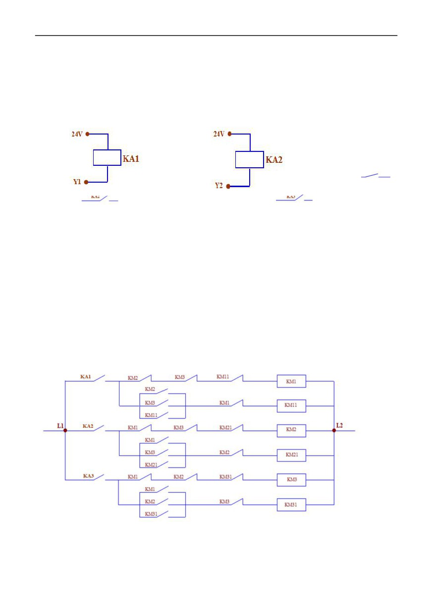
1、Schematic diagram of relay with open collectors Y1 and Y2:
2. Introd
In the foll
mally closed terminal,
Represe
resents relay KA1(Y1 control on
control board),
represents relay KA2 (Y2 control on control board),
represents relay KA3 (R1
on control board); KM1, KM2 and KM3 are contactors for controlling No.1, No.2 and No.3 variable frequency pumps
respectively, and KM11, KM21 and KM31 are contactors for controlling No.1, No.2 and No.3 power frequency pumps
respectively.
(Note: Figure 1 and Figure 2 below are only sketch logic diagrams, if you need fault relay or indicator light, add
them yourself.)
3. Introduction of contactor interlocking and self-locking (as shown in Figure 1)
KM11, KM2 and KM3 cannot be turned on when KM1 is turned on.
KM1 cannot be switched on when KM11 is switched on.
KM21, KM1 and KM3 cannot be connected when KM2 is connected.
When KM21 is switched on, KM2 cannot be switched on.
KM31, KM1 and KM2 cannot be connected when KM3 is connected.
KM1 cannot be switched on when KM11 is switched on.
Figure 1:
144
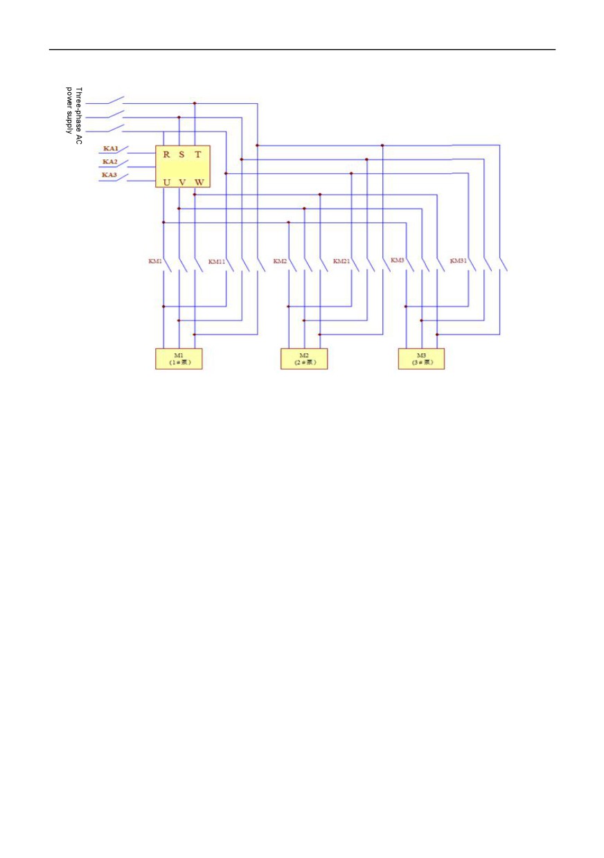
Figure 2:
Inverter
145
Warranty agreement
1 The warranty period of this product is 18 months (subject to the information of fuselage bar code). During the warranty
period, if the product breaks down or is damaged under normal use according to the instruction manual, our company is
responsible for free maintenance.
2 During the warranty period, if the damage is caused by the following reasons, a certain maintenance fee will be charged:
A. machine damage caused by errors in use and self-repair or modification without authorization;
B. machine damage caused by fire, flood, abnormal voltage, other natural disasters and secondary disasters;
C. hardware damage caused by man-made falling and transportation after purchase;
D. machine damage caused by not operating in accordance with the user's manual provided by our company;
E failures and damages caused by obstacles other than machines (e.g. external equipment factors);
3 In case of product failure or damage, please fill in the contents of Product Warranty Card correctly and in detail.
4. The collection of maintenance fees shall be subject to the maintenance price list newly adjusted by our company.
5 This warranty card will not be reissued under normal circumstances. Please keep this card and show it to maintenance
personnel during warranty.
6. If there is any problem in the service process, please contact our agent or our company in time.
146