HV390 Series Frequency Inverter. User Manual (Version: 3.1.14) - page 4
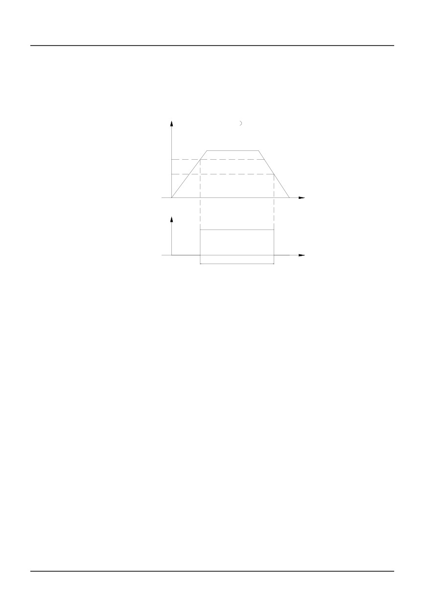
which is used inconjunction with parameters P6.12~P6.15.
output frequency(Hz
FDT
FDT level - FDT lag
Time(S)
0
Frequency
detecting
signal
Time(S)
T
Fig. 6-21 Frequency detection threshold 1 and 2
6
7:High limit frequency arriving
When the drive’s output frequency reaches high limit frequency, the terminal outputs indication
signal.
7
8: Low limit frequency arriving
When the drive’s output frequency reaches low limit frequency, the terminal outputs indication signal.
8
9: Overload signal
When overload occurs, the terminal outputs indication signal.
9
10: Over current stall
When over current stall occurs in running state, terminal outputs indication signal.
10
11: Over voltage stall
When over voltage stall occurs in running state, the terminal outputs indication signal.
11
12: External stoppingcommand
During running process, when external fault signal is received by the digital input terminals, the drive reports
ER11 fault, and the terminal outputs indication signal at the same time.
12
13: Preset counting value arriving
Set up counting value of the drive’s internal counter. The drive inputs counting pulses via external
80
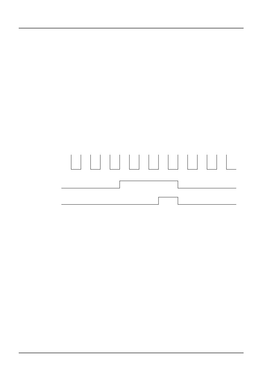
terminals DIi (I=1~5),and the drive’s internal counter counts this signal. When the preset value
arrives, Yi outputs an indication signal. Whenthe next external counting pulse signal arrives,Yi 's
output signal recovers, and the counter restarts to count again at the same time.
13
14: Specified counting value arriving
When DIi inputsexternal counting pulse signal and the countingvalue reaches specified value defined
by p6.17 (See Fig. 6-22), Y1 outputsan indication signal, Y1 does not recover until speicified value
arrives.
As shown in Fig. 6-22, if P6.16=5, P6.17=3, when DIiinputs the 3th pulse, Y1 outputs anindication
signal. When DIi inputs the 5th pulse, Y1 outputs specified value arriving signal. Y1 will recover when
the 6th pulse arrives.
0
1
2
3
4
5
1
2
3
DI1
Y1
Programmable
relay
1
Fig. 6-22 Preset counting value arriving and specified counting value arriving
14
15: Low voltage lockup signal
When DC busvoltage is lower than the low voltage limit, the panel LED displays “LU”, and the
terminal outputs indication signal at the same time.
15
16: Overload pre-alarm
According to PD.04~PD.06overload pre-alarm setup,when the output current is higher than thesetting value,
the terminal outputs indicationsignal.
16
17: Drive failure signal
When fault occurs, the terminal outputs indication signal
17
18: Zero speed running
When the drive’s running frequency is zero, the terminal outputs indication signal.
For example, in the following three conditionsthe terminals output indication signal:
81
z
FWD/REV dead time running period;
z
The phase when the setup frequency islower than the start frequency when theinverter starts
from zero frequency;
z
In Dec process output frequency is lowerthan initial frequency of DC injectionbraking.
18
19:End signal of stage of program operation
In program operation mode, when a stage is finished, the inverter outputs a pulse with width of
250ms.
19
20: End signal of stage of program operation
In program operation mode, when a cycle is finished, the inverter outputs a pulse with width of
250ms.
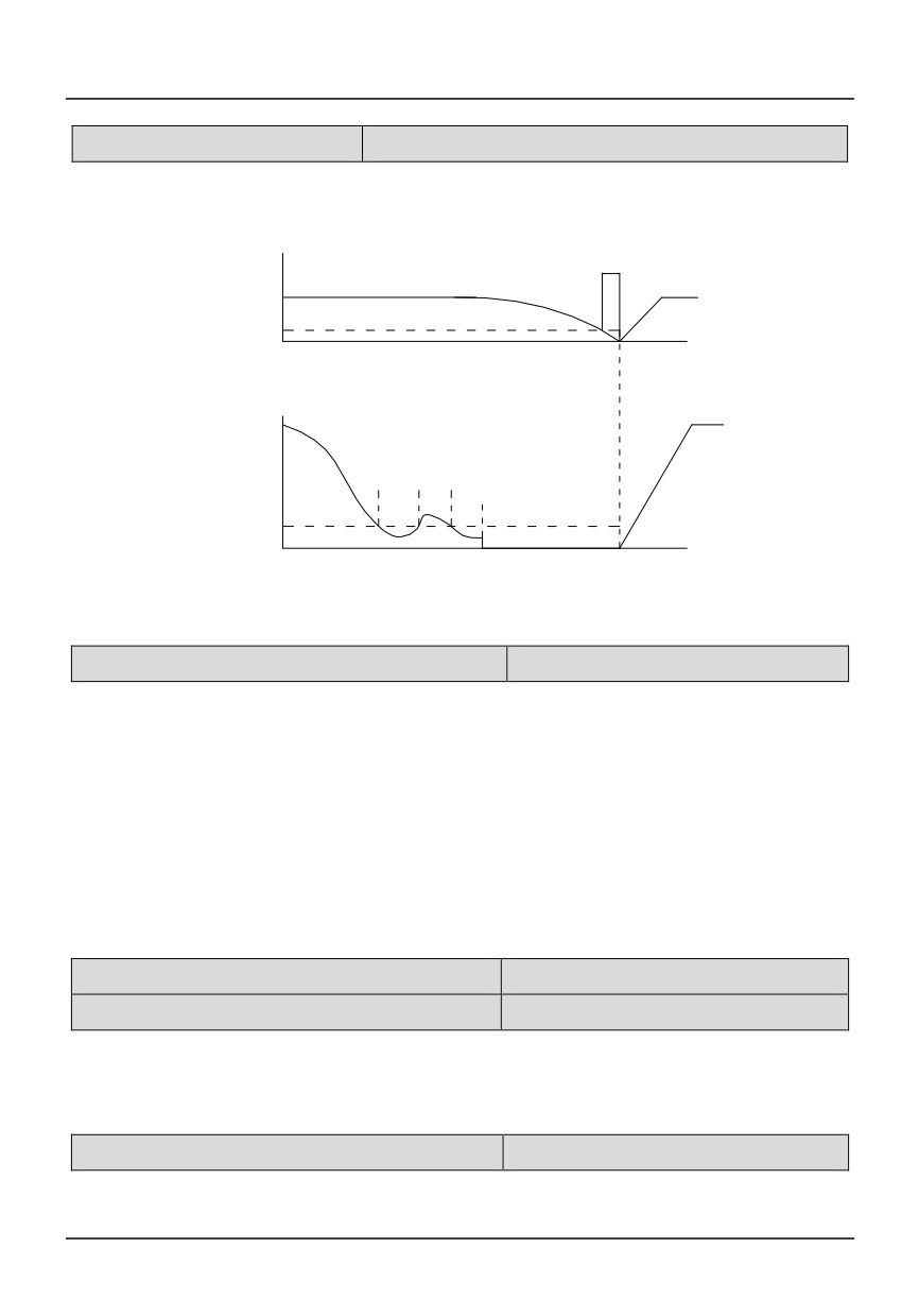
P6.11 Frequency arriving width (FAR)
Setting range:0.0~10.00Hz
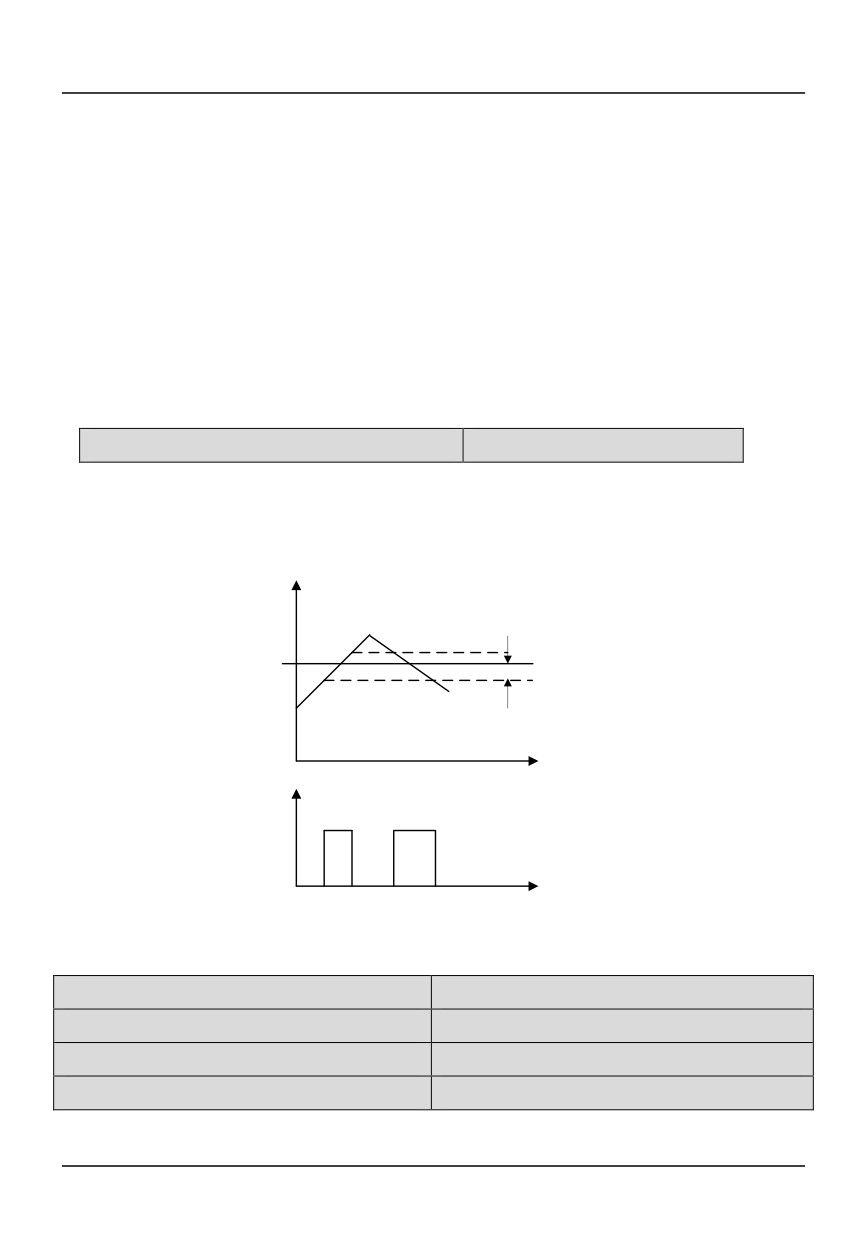
When output terminal function is selected as frequency arriving signal, this function is used to detect
output frequency range. When error between output frequency and setting value is less than FAR, the
terminal outputs indication signal, as shown in Fig.6-24.
Output frequency
Detection width
Time
Yi
Time
Fig.6-24 FAR and FAR detection width
P6.12 FDT1 level
Setting range: 0.0~600.0Hz
P6.13 FDT1 lag
Setting range: 0.0~10.00Hz
P6.14 FDT2 level
Setting range: 0.0~600.0Hz
P6.15 FDT2 lag
Setting range: 0.0~10.00Hz
82
If output frequency exceeds certain value, the terminal outputs indication signal, and this signal is
called FDT level.
If output frequency decreases, the terminal continues to outputs indication signal, until the output
frequency is lowered to the FDT signal width and exceeds certain width, this width is called FDT signal lag,
as shown in Fig.6-21 and 6-23.
P6.16 Preset value arriving
Setting range:0~9999
P6.17Specified value arriving
Setting range:0~9999
For P6.16 and P6.17 function, please refer to definition of terminal function 13, 14.
P6.18 Terminal logic
Setting range:0~255
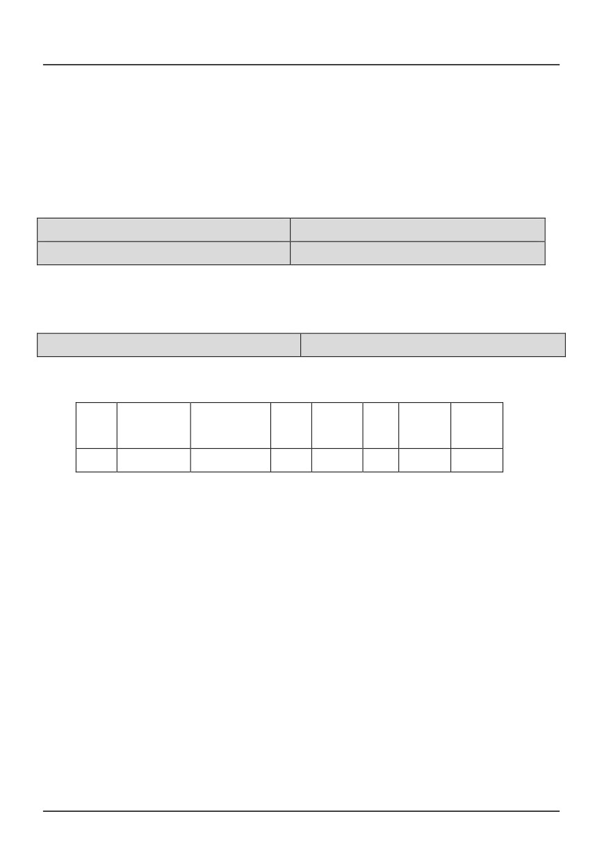
This parameter defines positive or negative logic of terminals.
Y1
RESERVE
RESERVED
DI5
DI4
DI3
DI2
DI1
D
Bit7
Bit6
Bit5
Bit4
Bit3
Bit2
Bit1
Bit0
Note:
a.
If bit 0 is set to 0, it means positive logic, and 1 for negative logic. Factory setting of all terminals
are positive logic;
b.
In positive logic mode, terminal DIi is enabled if it is connected to the common terminal, and
disabled if disconnected;
In negative logic mode, terminal DIi is disabled if it is connected to the common terminal, and
enabled if disconnected;
In positive logic mode, terminal Yi closes when its output signal is valid;
In negative logic mode, terminal Yi opens when its output signal is valid;
Only decimal number can be set to the drive (including display). When negative logic is selected,
conversion from binary code to Hex value isshown as below:
Setting value ==(2*Y1)7+(2*DI5)4 +(2*DI4)3 +(2*DI3)2+(2*DI2)1+DI1
For example,
if DI5 and DI4 select negative logic and others are positive logic, then:
83
Setting value =(2*1)4+(2*1)3 +(2*0)2+(2*0)1+0=16+8=24
P7 Analog input terminal function
P7.00 AI1 filter time
Setting range: 0.05-5.00S
P7.01 Minimum AI1
0.0-100.0%(10V)
P7.02 Frequency corresponding to P7.06
0.00 ~ Maximum frequency
P7.03 Maximum AI1
0.0-100.0%(10V)
P7.04 Frequency corresponding to P7.08
0.00 ~ Maximum frequency
P7.05 AI2 filter time
Setting range: 0.05-5.00s
P7.06 Minimum AI2
0.0-100.0%(10V/20mA)
P7.07 Frequency corresponding to P7.06
0.00 ~ Maximum frequency
P7.08 Maximum AI2
0.0-100.0%(10V/20mA)
P7.09 Frequency corresponding to P7.09
0.00 ~ Maximum frequency
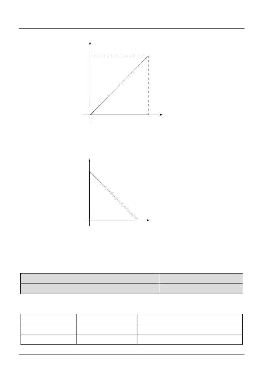
Reference signal from external input (AI1, AI2) is filtered and amplified, and then its relationship with
frequency setting is shown as curve 1 in Fig. 6-25 or curve 2 in Fig.6-26.
AI2 can input current signal (4~20mA), P7.06 should be set to 20% except that S1 (AI2) is in “I”
position,
P7.10 FWD/REV dead time range
Setting range: 0~10% Maximum input signal
If polarity control is selected (P0.06= 2 or 3), FWD/REV dead time is set by this parameter. Refer to
parameter P0.06 and fig 6-1 for details.
P7.11 AI0 filter time
Setting range: 0.05-5.00S
P7.12 Minimum AI0
0.0-100.0%
P7.13 Frequency corresponding toP7.12
0.00 ~ Maximum frequency
P7.14 Maximum AI0
0.0-100.0%
P7.15 Frequency corresponding to P7.13
0.00 ~ Maximum frequency
Reference signal(AI1) from keypad potentiometer is filtered and amplified, and then its relationship with
frequency setting is shown as curve 1 in Fig. 6-25 or curve 2 in Fig. 6-26.
84
Hz
output frequency
Maximum value
corresponding to the
frequency
(F7.04)
Minimum value
Maximum value
Input signal
0
(F7.01)
Minimum value corresponding
(F7.03)
to the frequency(F7.02)
Fig. 6-25 curve 1: relationship between reference and frequency setting
output frequency
Hz
Minimum value corresponding to the
frequency(F7.02)
Input signal
0
Minimum
Maximum value
(F7.01)
(F7.03)
Maximum value corresponding to the
frequency(F7.04)
Fig. 6-26 curve 2: relationship between reference and frequency setting
P8 Analog output terminal
P8.00 AO1 output selection
Setting range:0~9
P8.01 AO2 output selection
Setting range:0~9
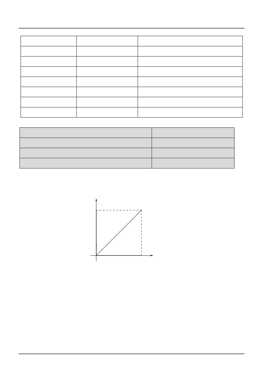
Inverter's state represented by analog outputsignal is defined by the function codes P8.00 and P8.01,
as shown below.
P8.00/P8.01
Drive state
Description
0
Running frequency/speed
0~ highest running frequency/speed
1
Frequency setting/speed
0~ highest running frequency/speed
85
2
Output current
0~ 2×rated current
3
Output voltage
0~+200% rated voltage
4
Output torque
-200%~+200% rated torque current
5
PI reference
0~10V
6
PI feedback
0~10V
7
Bus voltage
0-800V
8
Analog input AI1
0-10V
9
Analog input AI2
0-10V
P8.02 Minimum AO1
Setting range:0.00~100.0%
P8.03 Minimum value corresponding to F8.02
Setting range:0.00~100.0%
P8.04 Maximum AO1
Setting range:0.00~100.0%
P8.05 Maximum value corresponding to F8.04
Setting range:0.00~100.0%
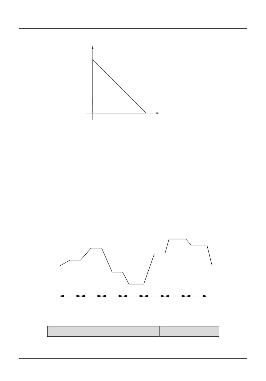
This function code is used to setup maximum/minimum value of analog output signal (0~10V), and the
relationship between these values and P8.00 is shown in Fig. 6-27 and 6-28.
Output(F8.00)
Corresponding to
the maximum
(F8.05)
AO1 Output signal
0
Minimum value
Maximum value
(F8.02)
(F8.04)
Corresponding to the minimum
value(F8.03)
Fig. 6-27 Relationship between maximum/minimum AO1 and F8.00
For example, connect AO1 with a voltage meter (range: 0~5V) to indicate operating frequency, and the
range of operating frequency is
0~50Hz
(Maximum frequency=50Hz), then F8.00=0(=frequency),
F8.02=0(=0V), F8.03=0(0Hz), F8.04=50%(=5V), F8.05=100%(=50Hz).
86
output(F8.00)
Corresponding to the
minimum value
(F8.03)
AO1 Output signal
0
Minimum value
Maximum value
(F8.02)
(F8.04)
Corresponding to the
maximum
(F8.05)
Fig. 6-28 Relationship between maximum/minimum AO1 and F8.00
P9 Program operating parameters
P9 parameter group is function code of programming operation.
Both programming operation and multi-frequency operation are used for realizing the inverter's
variable speed running accordingto certain regulations.
One cycle of programming operation is shown in Fig. 6-29, f1~f7 and T1~T7 will be defined in the
following function codes.
f6
f7
f2
f5
f1
f3
f4
T1
T2
T3
T4
T5
T6
T7
Fig. 6-29 Programming operation
P9.00 Programming operation function
Setting range:0, 1,2
0: Single cycle (Stop after a single cycle)
87
1: Continuous cycle (Continue cycle operation according to setup phase parameters)
2: Maintain the final value (maintain the non-zero operating frequency of last stage after completing
one cycle)
P9.01 Programming operation time setting unit
Setting range:0、1
0:second
1:minute
P9.02 Stage timing T1
Setting range:0.0~3600.0
P9.03 Stage timing T2
Setting range:0.0~3600.0
P9.04 Stage timing T3
Setting range:0.0~3600.0
P9.05 Stage timing T4
Setting range:0.0~3600.0
P9.06 Stage timing T5
Setting range:0.0~3600.0
P9.07 Stage timing T6
Setting range:0.0~3600.0
P9.08 Stage timingT7
Setting range:0.0~3600.0
P9.09 Stage timingT8
Setting range:0.0~3600.0
P9.10 Stage timingT9
Setting range:0.0~3600.0
P9.11 Stage timingT10
Setting range:0.0~3600.0
P9.12 Stage timingT11
Setting range:0.0~3600.0
P9.13 Stage timingT12
Setting range:0.0~3600.0
P9.14 Stage timingT13
Setting range:0.0~3600.0
P9.15 Stage timingT14
Setting range:0.0~3600.0
P9.16 Stage timingT15
Setting range:0.0~3600.0
Parameters P9.02~P9.16 are used to set running time of each stage.
P9.17 T1Running mode
Setting range:0~7
P9.18 T2Running mode
Setting range:0~7
P9.19 T3Running mode
Setting range:0~7
P9.20 T4Running mode
Setting range:0~7
P9.21 T5Running mode
Setting range:0~7
88
P9.22 T6Running mode
Setting range:0~7
P9.23 T7Running mode
Setting range:0~7
P9.24 T8Running mode
Setting range:0~7
P9.25 T9Running mode
Setting range:0~7
P9.26 T10Running mode
Setting range:0~7
P9.27 T11Running mode
Setting range:0~7
P9.28 T12Running mode
Setting range:0~7
P9.29 T13Running mode
Setting range:0~7
P9.30 T14Running mode
Setting range:0~7
P9.31 T15Running mode
Setting range:0~7
P9.17~P9.31 are used to set operating direction and Acc time of each stage:
0 :Run forward Acc/Dec time is 1; 1:Run forward Acc/Dec time is 2; 2 :Run forward Acc/Dec time is
3; 3:Run forward Acc/Dec time is 4;4 : Run reverse Acc/Dec time is 1; 5 : Run reverse Acc/Dec time is 2; 6 :
Run reverse Acc/Dec time is 3; 7 : Run reverse Acc/Dec time is 4;
P9.32 Record function
Setting range:0~2
0: Record function disabled
In programming operation state, if user press stop key, counter value of present program will not be
recorded. Input running command again, program will run from the first stage.
1: Record function enabled
In programming operation state, program will pause when stop key is pressed. Input running command
again, program will run from the breakpoint.
When the drive stops, user can clear counter value of current program by setting function code P9.00 again.
2: Record function enabled ,
In programming operation state, program will pause when stop key is pressed. Input running command
again, program will run from the breakpoint,
When the drive stops, user can clear counter value of current program by setting function code P9.00 again.
PA PID parameter
FA parameter group defines parameters of PID control function.
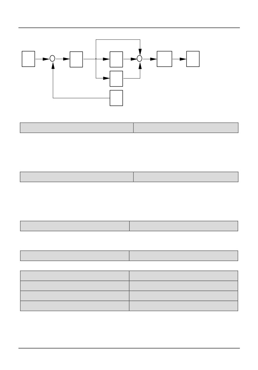
PID control function diagram is shown below, where P is proportional gain, I is integration time, D is
differential time.
89
+
+
+
Reference
Acc/
Frequency
P
I
Dec
-
+
D
Feedback
PA.00 PID control characteristic
Setting range:0、1
0: Positive characteristic
The Motor speed is required to increases with thereference speed.
1: Negativecharacteristic
The motor speed isrequired to decrease when the reference valueincreases.
PA.01 Reference selection
Setting range:0、1、2、3
0:Panel Digital setting
1: External analog signal AI1
2: External analog signal AI2
3:Rs-485 communication setting
PA.02 Feedback channel selection
Setting range:0、1
1: External analog signal AI1 (0~10V)
2: Analog signal AI2 (0~10V or 4~20mA)
PA.03 Digital setting of reference
Setting range:0.00V~10.00V
Digital reference is set by UP/DOWN keypad.
PA.04 Minimum referenc
Setting range:0.0~100.0%
PA.05 Maximum reference
Setting range:0.0~150.0%
PA.06 Minimum feedback
Setting range:0.0~100.0%
PA.07 Minimum feedback
Setting range:0.0~150.0%
By setting parameter PA.04~PA.07, actual value of reference and feedback can be displayed
accurately.
90
PA.08 Proportional gain
Setting range:0.0~10.00
PA.09 Integration timeTi
Setting range:0.00(no integration)~99.99s
PA.10 Integration timeTi
Setting range:0.00(no differentiation)~99.99s
PA.11 Sample cycle T
Setting range:0.00(do not specify T)~99.99s
Setup parameters of PID regulator
PA.12 Error limit
Setting range:0.0~15.0%((corresponding to close loop input))
Definition: relative error of close loop system = | input value
- feedback value
| /
inputvalue×100%.
If relative error of close loop system is biggerthan the setting value of error limit, then thePID
regulator will adjust the error.
If relative error of close loop system is in the setting range of error limit, then stop PIDregulating, PID
regulator's output maintainsconstant.
PA.13 Level of abnormal feedback signal
Setting range:0~100%
This function code defines abnormal level of feedback signal.
Definition: Abnormal level = |reference - feedback|/reference×100%
PA.14 Detection time of abnormal feedback signal
Setting range:0~3600S
This function code defines the detection time of abnormal feedback signal. When feedback signal
exceeds abnormal level and hold time exceeds the detection time, action at abnormal signal (ER.06) will be
executed. When this parameter is set to 0, the abnormal feedback signal detect function is disable.
PA.15 Reserved
PA.16 PID Sleep control
Setting range:0~2
0: No sleep function;
1: Internal waking up, which is controlled by parameters PA.17~PA.20;
2: External input terminal, which is controlled by terminal function 26 (PID waking terminal), is
decided by parameter P6.02~P6.08.
PA.17 Delay time of sleeping
Setting range:0.0~3600S
PA.18 Sleeping frequency
Setting range:0.0~600.0Hz
PA.19 Delay time of waking
Setting range:0.0~60S
91
PA.20 Waking value
Setting range:0.0~100%actual value
For PID control, parameters PA.17~ PA.20 define delay time of sleeping, sleeping frequency, delay
time of waking and waking value.
PID input
Delay time of waking
( PA. 19)
Actual value
( PA. 20)
PID
(Output frequency)
td=
Delay time of sleeping
PA. 17
t<td
td
Sleeping frequency
time
( PA. 18)
stop
run
Fig. 6-30 PID sleeping and waking
Pb Traverse function
Pb.00 Traverse mode
Setting range:0、1
0: Auto mode
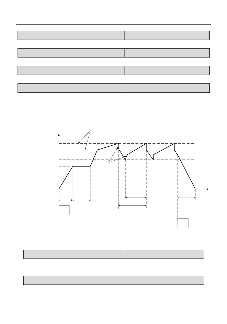
At first, the drive operates at preset frequency oftraverse operation (Pb.01) for certain time (Pb.02),
andthen enter traverse mode automatically.
1: Manual mode
If the multi-function terminal (DIi is set to terminal function 20) is enabled, the drive will enter traverse
mode. If theterminal is disabled, the drive will exit traverse operationand operate at the preset traverse
frequency (Pb.01).
Pb.01 Preset traverse frequency
Setting range:0.00~600.0Hz
Pb.02 Hold time of preset traverse frequency
Setting range:0.0~3600s
Pb.01 defines drive’s operating frequency before entering traverse operation. In auto mode, Pb.02
defines the hold time of preset traverse frequency before traverse operation. In manual mode, Pb.02 setting
is invalid. Refer to Fig. 6-31 for details.
Pb.03 Preset central frequency
Setting range:0.00~400.0 Hz
Traverse operation is shown in Fig. 6-31.
92
Pb.04 Travers amplitude
Setting range:0.0~50%
Travers amplitude = Preset central frequency×Fb.04
Pb.05 Step frequency
Setting range:0.0~50%
Refer to Fig. 6-31. If it is set at 0, then there willbe no step frequency.
Pb.06 Traverse cycle
Setting range:0.1~999.9S
It defines the period of traverse operationincluding rising and falling time.
Pb.07 Rise time oftriangular wave
Setting range:0.0~100.0%
It defines the rising time (Pb.06×Pb.07 s) of traverse operation, and falling time (Fb.06×(1-Fb.07) s).
Please refer to Fig. 6-31.
Traverse amplitude
Operating frequency Hz
AW= Fset*Pb.04
Upper limit of traverse frequency
FH
central frequency Pb.03
Lower limit of traverse frequencyFL
Preset traverse frequency
Step frequency
Pb.01
=AW*Pb.05
t
Accerlate
Hold time of
Rise time of
Decelerate
according to
preset traverse
triangular wave
according to
=Pb.07*Pb.06
Acc time
frequency
Dec time
Pb.02
Traverse cyclePb.06
Run command
Stop command
Fig. 6-31 Traverse operation
PC Communication and Bus control function
Pc.00 Baud rate selection
Setting range:0~5
Select baud rate of serial communication
0:1200BPS
1:2400 BPS
2:4800 BPS
3:9600 BPS
4:19200 BPS5:38400 BPS
Pc.01 Data Format
Setting range:0~8
Data format of serial communication protocol:
0:
8,N,2 For RTU
(MODBUS) (Default)
93
1:
8,E,1 For RTU
(MODBUS)
2:
8,O,1 For RTU
(MODBUS)
3:
7,N,2 For ASCII (MODBUS)
4:
7,E,1 For ASCII (MODBUS)
5:
7,O,1 For ASCII (MODBUS)
6:
8,N,1 free communication format
7:
8,E,1 free communication format
8:
8,O,1 free communication format
9:
8,N,2 For RTU (MODBUS)master model
Pc.02 Local address
Setting range:1~32
When the host is communicating with severalinverters, inverter's address is defined in thisfunction code.
。
Pc.03 Communication timeout detect
Setting range:0.0、0.1~100.0s
The setting value is 0:No communicationovertime protection.
The setting value isn't 0, in RS485communication control mode, if thecommunication between the
inverter and thehost is still abnormal in the time defined by Pc.03, ER05 fault is displayed and the
inverteracts according to the setting value ofPc.05.
Pc.04 Response delay
Setting range:0 ~1000ms
Response delay refers to the time from the drivereceiving and executing the command of the hostto
returning reply frame to the host.
Pc.05 EEROM Store function
Setting range:0、1
0:The parameter is stored into EEROM in communication.
l:The parameter is not stored into EEROM in communication.
Pd Faults and protection parameters
Pd.00 Motor overloadprotection mode
Setting range:0,1,2
0: No protection
1: Common motor protection
Since cooling conditions of common motordeteriorates at low speed, please lower the motor’s
thermalprotection threshold at this time.
2: Variable frequency motor protection
94

Since the variable frequency motorapplies forced air-cooling, the protection parametersneedn't be
adjusted during low speed running.
Pd.01 Motor overloadprotection factor
Setting range:20.0%-150.0%
Heat dissipation becomes worse at low frequency, and high temperature will reduce service life of the
motor. Through setting threshold of the electronic thermal overload relay, overload current and current limit
will be proportionally adjusted.
When motor capacity is lower than that of the drive, this function is used provide overheat protection for
the motor.
When several motors are driven by the same variable speed drive, this function is disabled. When
display readings reaches 100%, overload protection will be trigged
Pd.02 Over voltage stall selection
Setting range:0,1
Over voltage stall selection
0: Disabled;
1:Enabled
In inverter's Dec process, the actual motorspeed may be higher than the outputsynchronized speed
of the inverter due to theload inertia. At this time, the motor will feed theenergy back to the inverter, resulting
in thevoltage rise on the inverter's DC bus. If nomeasures being taken, tripping will occur dueto over
voltage.
The overvoltage stall protection function is thatduring the Dec running, the inverter detects thebus
voltage and compares it with the stallovervoltage point defined by PD.03. If the busvoltage exceeds the stall
overvoltage point, theinverter will stop reducing its output frequency.When the detected bus voltage is lower
thanthe point, the Dec running will be restored, asshown in Fig.6-32.
95
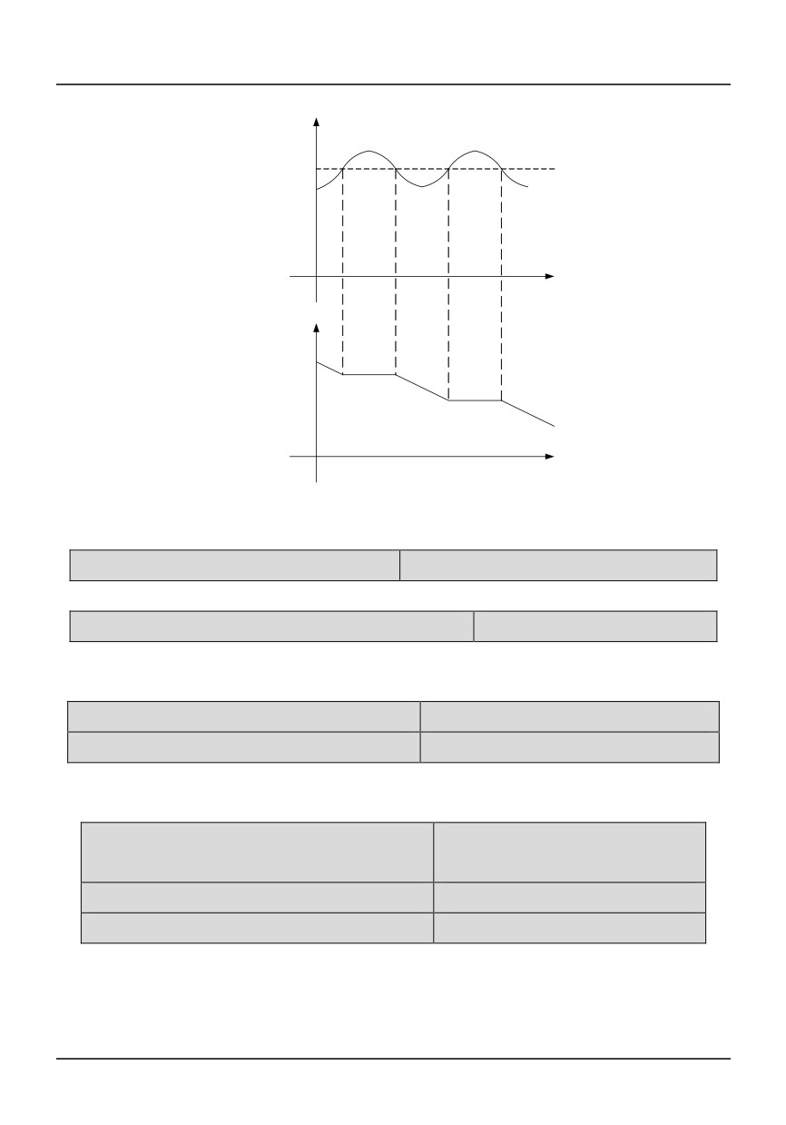
DC Bus voltage
Stall over voltage point
time
Output frequency
time
Fig. 6-32 Over voltage stall function
Pd.03 Stall over voltage point
Setting range:115.0%~150.0%
Stall over ovtage point = 115.0%~150.0% inverter’s rated peak voltage
Pd.04 Selection of overload pre-alarm detection
Setting range:0,1
0:Overload is only monitored during constant speed operation, and alarms when overload occurs;
1:Overload is monitored all the time, and alarms when overload occurs;
Pd.05 Overload detection threshold
Setting range:20-180%
Pd.06 Overload pre-alarm delay
Setting range:0-60.0s
PD.05 defines the threshold value for overload alarm. It is a percentage of rated current.
Setting range:20.0~150.0%(drive’s
Pd.07 Auto current limiting threshold
rated output current)
Pd.08 Frequency decrease rate during
Setting range:0.00-99.99Hz/S
Pd.09 Action mode of auto current limiting
Setting range:0、1、2
Auto current limiting function is used to limit theload current under the preset current (PD.07) in real
timeto avoid trip due to over-current. This function isespecially useful for the applications of larger
loadinertia or sharp change of load.
96
PD.07 defines the threshold for current limiting. Itssetting is a percentage of drive’s rated current Ie. PD.08
defines the decreasing rate of outputfrequency when the drive is in auto currentlimiting status. If PD.08 is
set too small, overload fault may occur.If PD.08 is set too big, the drive may be in energygeneration status
for long time that may result inovervoltage protection.
The action mode of auto current limiting functionis decided by PD.09:
PD.09= 0: disabled;
PD.09= 1:auto current limiting is effective duringacceleration or deceleration but ineffective
atconstant speed;
PD.09= 2: auto current limiting is effective duringacceleration/deceleration and constant speed;
Pd.10 Auto reset
Setting range:0~5
0: disabled;
1~5: times of fault reset;
Pd.11 Auto reset interval
Setting range:2~20s
When fault occurs, the drive stops output. After the time defined by PD.11, the drive resets fault
automatically and continue running.
PD.10 defines the times of auto fault reset. If PD.10=0, auto reset function is disabled, and user can only
reset fault in manual mode.
Pd.12 Relay action in Auto reset
Setting range:0、1
This parameter determine the relay action in auto reset period of the inverter.
0:no action
1:action
Pd.13Act selection at undervoltage fault
Setting range:0、1、2
0:
When undervoltage occurs, fault relay does not act, and fault code will not be saved.
1:
When undervoltage occurs during running, fault relay acts and fault code will be saved. When
undervoltage occurs during stop state, fault relay does not act, and fault code will not be saved.
2:
When undervoltage occurs in running or stopping state, fault relay acts and fault code will be
saved.
Pd.14Input missing phase (valid for 132kw model)
Setting range:0~1
0: Disabled; No input phase protection function
1: Enabled; Allow input phase protection (three-phase power input is valid)
97
Pd.15Output missing phase (valid for 132kw model)
Setting range:0~1
0: Disabled;No output phase protection function
1: Enabled; Allow output phase protection (three-phase power input is valid)
Pd.16 Under voltage point
380V voltage level Setting range:250~
440 220V voltage level Setting range:
200~260
380V voltage level :default value is 400v(DC voltage).
220V voltage level :default value is 250v(DC voltage).
In some case when the input voltage is low or not stable, the value can be adjusted to avoid under
voltage fault.
PE Factory reserved
PE.00 Keyboard frequency setting lock function
Setting range:0~1
0:Keyboard frequency settings are not locked, you can change the frequency of the inverter settings
by keyboard keys;
1:The keyboard frequency setting lock can not change the frequency setting frequency of the
inverter through the keyboard up and down key, and can only change the frequency setting frequency of the
converter by changing the P0.11
PE.01 Terminal start delay
Setting range:0.0~20.0s
Used to set the setting Di terminal from breaking to the closed state changes, the frequency converter
for the delay time of the change
PE.02 Terminal stop delay
Setting range:0.0~20.0s
Used to set the di terminal from the closed to the broken state changes, the frequency converter for the
delay time of the change
PE.03 MUDBUSrespond
Setting range:0~1
0:MODBUS protocol response write command
1:MODBUS protocol does not respond to the write command
PE.04 Acceleration and deceleration time switching
Setting range:0.00~600.00Hz
frequency
When the deceleration time switching frequency is 0, according to the 1 inverter deceleration time
operation, deceleration time switching frequency is not 0, when the operation frequency is less than pe.04,
98
according to the first deceleration time operation, when the operation frequency is greater than pe.04, in
accordance with the second plus deceleration time operation.
PE.05 is reserved for special users
PF Factory reserved
PF.00~PF.19 are reserved parameters for individual consumer.
PH Display function
PH.00 running displayparameters selection
Setting range:0~14
HV390 drive has 15 state parameters in running state. User can scroll through them by pressing ►►
key during running process. Function code PH.00 defines the default display parameter after starting, which
includes:
0: Frequency setting
1: Running frequency
2: Output current
3: Output voltage
4: Bus voltage
5: Overload rate
6: Preset line speed
7: Running line speed
8: Output torque
9: PI reference
10:PI feedback
11:Reserved
12:Analog input AI1
13:Analog input AI2
14:I/O status(0~511)
Inpt/output IO status correspond as blow:
relay1
Y1
reserved
reserved
DI5
DI4
DI3
DI2
DI1
Bit8
Bit7
Bit6
Bit5
Bit4
Bit3
Bit2
Bit1
Bit0
PH.01 Display parameters at stop
Setting range:0~8
99
HV390 drive has 9 state parameters in stopping state. User can scroll through them by pressing ►►
key during stop state.
Function code PH.01 defines the default display parameter upon power on, which includes:
0: Frequency setting
1: Preset line speed
2: DC Bus voltage
3: Reserved
4: Analog input AI1
5: Analog input AI2
6: I/O status
7:external counting value
8: PI reference
9:PI feedback
PH.02Line speed factor
Setting range:0.1~100
When line speed is displayed, line speed = Output frequency × Line speed factor
PH.03Inverter power
Display inverter power
PH.04 IPM heatsinktemperature 1
Setting range:0~100℃
PH.05 IPM heatsinktemperature2
Setting range:0~100℃
Display IPM heatsink temperature.
Note: some models have this function
PH.061st fault type
Setting range:
PH.072nd fault type
Setting range:
PH.083rd fault type
Setting range:
PH.06~PH.08 are used for memorizing thelatest three fault types, and can record thevoltage, current,
frequency and terminal stateat the last fault (in PH.09~PH.13) for checking.
Please refer to Chapter 7 for fault descriptions.
PH.09 Bus voltage at last fault(V)
Setting range:0~999
PH.10 Output current at last fault (A)
Setting range:0~999.9
PH.11Frequency setting at last fault(Hz)
Setting range:0~400.0
100
PH.12Running frequency at last fault(Hz)
Setting range:0~400.0
PH.13I/O state at last fault
Setting range:0~511
PH.14Total operating time
Setting range:0~9999
PH.15 Software version
Setting range:0~9.99
PH.16Keyboard Software version
Setting range:0~9.99
PH.13At last time, I/O Status correspond as blow:
relay1
Y1
reserved
reserved
DI5
DI4
DI3
DI2
DI1
Bit8
Bit7
Bit6
Bit5
Bit4
Bit3
Bit2
Bit1
Bit0
101
Chapter 7 Fault diagnosis and troubleshooting
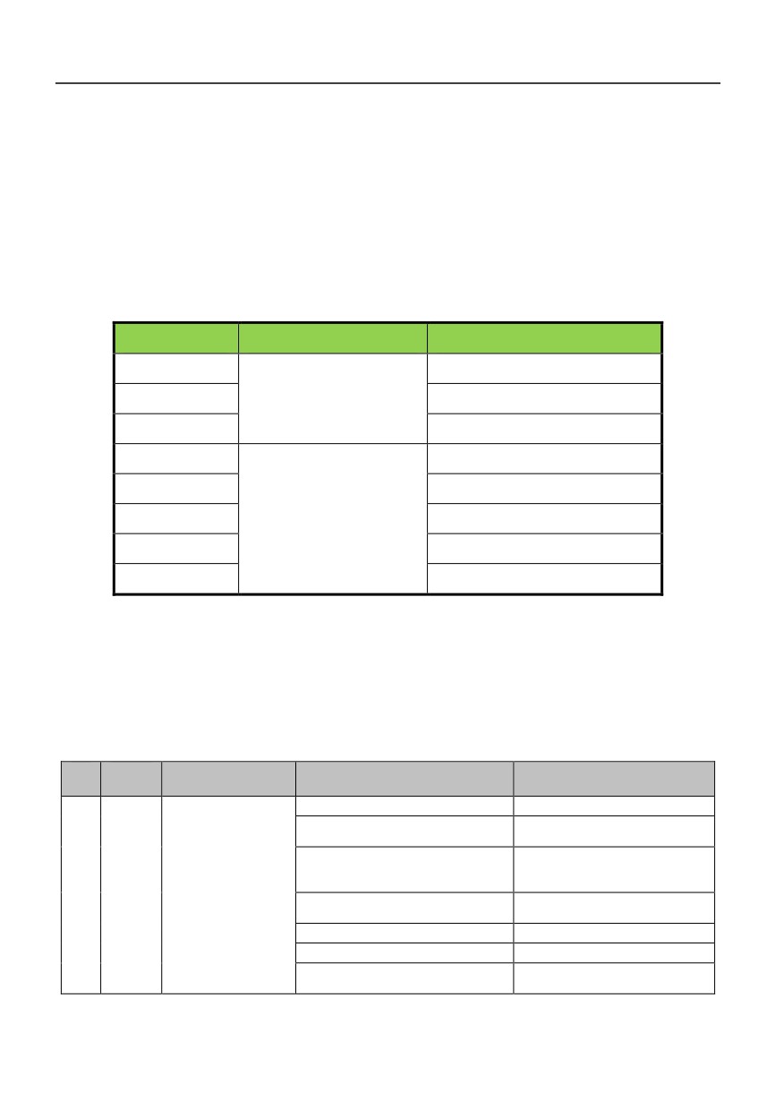
7.1 Fault query at fault
If control power supply is normal at fault, the drive will be in fault displaying status all the times.
At this time, user can enter parameter group PH to get related information about the failure, such as
output frequency, frequency setting, output current, rotating direction, operating condition, and the
3 latest faults, which is shown in the table below.
Fault code
Display content
Description
PH.06
1st fault type
PH.07
Fault code
2nd fault type
PH.08
3rd fault type
PH.09
Bus voltage at last fault
PH.10
Output current at last fault
Date
PH.11
Frequency setting at last fault
(With unit)
PH.12
Running frequency at last fault
PH.13
I/0 terminal’s state at last fault
7.2 List of Fault and Alarm Information
HV390 serial inverter is equipped with complete protection functions to provide efficient protection
while utilizing its performance sufficiently. Some failure instructions may be displayed during operation.
Compare the instructions with the following table and analyze, decide the causes and solve failures.
For damages on units or questions that can’t be resolved, please contact with local distributors/agents,
service centers or manufacturer for solutions.
Failur
Failure
Failure description
Potential causes
Solutions
e No
code
Low grid voltage
Check input power supply
Startup too fast during motor
Restart after the motor stops
operation
rotating
Increase the acceleration time
Rotating inertial of load is very large
Over current
and reduce the occurrences of
and shock load is very heavy
protection when
sudden change of load
1
oc1
Improper setting of motor
acceleration
Set motor parameters properly
operation
parameters
Set start-up frequency too high
Decrease start-up frequency
Acceleration time is too short
Lengthen acceleration time
Adjust V/F curve setting and
Set V/F curve ratio too large
torque boost
102
Failur
Failure
Failure description
Potential causes
Solutions
e No
code
Replace with inverter with proper
Power level of inverter is small
model
Low grid voltage
Check input power supply
Choose appropriate energy
Rotating inertial of load is too large
Over current
braking components
protection when
Improper setting of motor
2
oc2
Set motor parameters properly
deceleration
parameters
operation
Deceleration time is too short
Lengthen deceleration time
Replace to inverter with proper
Power level of inverter is small
model
Sudden change of load during
Decrease load’s abrupt frequency
Over current
operation
change and amplitude
protection when
Improper
setting
of
motor
3
oc3
Set motor parameters properly
operation with
parameters
constant speed
Replace to inverter with proper
Power level of inverter is small
model
Low grid voltage
Check input power supply
Startup too fast during motor
Restart after the motor stops
operation
rotating
Increase the acceleration time
Rotating inertial of load is very large
and reduce the occurrences of
and shock load is very heavy
sudden change of load
Igbt module
Improper setting of motor
4
occ1
protection in Acc
Set motor parameters properly
parameters
process
Set start-up frequency too high
Decrease start-up frequency
Acceleration time is too short
Lengthen acceleration time
Adjust V/F curve setting and
Set V/F curve ratio too large
torque boost
Replace with inverter with proper
Power level of inverter is small
model
Low grid voltage
Check input power supply
Choose appropriate energy
Rotating inertial of load is too large
braking components
Igbt module
Improper setting of motor
5
occ2
protection in Dec
Set motor parameters properly
parameters
process
Deceleration time is too short
Lengthen deceleration time
Replace to inverter with proper
Power level of inverter is small
model
Sudden change of load during
Decrease load’s abrupt frequency
Igbt module
operation
change and amplitude
protection in
Improper
setting
of
motor
6
occ3
Set motor parameters properly
constant speed
parameters
process
Replace to inverter with proper
Power level of inverter is small
model
Over voltage
Motor short to ground
Check motor wiring
protection when
Abnormal input power supply voltage
Check input power supply
10
ou1
acceleration
Fast start-up again when motor
Start again after the motor stop
operation
operates with high speed
rotating
Motor short to ground
Check motor wiring
Over voltage
protection when
Choose appropriate energy
11
ou2
Rotating inertial of load is too large
deceleration
braking components
operation
Deceleration time is too short
Lengthen deceleration time
103
Failur
Failure
Failure description
Potential causes
Solutions
e No
code
Over voltage
Motor short to ground
Check motor wiring
12
ou3
protection when
operation with
Abnormal input power supply
Check input power supply
constant speed
Lower the ambient temperature
Ambient over-temperature
and strengthen ventilation and
radiation.
Clean the dusts, wools and other
Blockage of air duct
foreign objects in the air duct.
Heatsink 2 over
15
oH2
temperature
Check whether fan wirings are
protection
well connected.
Fan failure
Replace a new fan of the same
model.
Inverter module failure
Seek for technical support
Temperature detection circuit failure
Seek for technical support
The power voltage is lower than the
minimum operating voltage of the
Check input power supply
16
LU
Power under voltage
equipment
The internal power source of the
Seek for technical support
inverter is abnormal
Lower the ambient temperature
Ambient over-temperature
and strengthen ventilation and
radiation.
Clean the dusts, wools and other
Blockage of air duct
Heatsink 1 over
foreign objects in the air duct.
17
oH1
temperature
Check whether fan wirings are
well connected.
protection
Fan failure
Replace a new fan of the same
model.
Inverter module failure
Seek for technical support
Temperature detection circuit failure
Seek for technical support
Input power under voltage
Check input power supply
Fast start-up when motor operates
Start again after the motor stop
with high speed
rotating
Keep overloading for a long period of
Shorten the overloading time and
time
reduce load
Inverter overload
18
oL1
Acceleration and deceleration time is
Prolong
the
protection
too short
acceleration/deceleration time
Adjust V/F curve setting and
V/F curve ratio is set too large
torque boost
Replace to inverter with proper
Power level of inverter is small
model
Input power under voltage
Check input power supply
Prevent the motor rotation from
Motor rotation is blocked or load
blocking and reduce the load
mutation occurs
mutation
Motor overload
19
oL2
Common motor maintains running
Replace the common motor with
protection
under heavy load for a long period of
variable frequency motor or
time
improve the running frequency
Motor overload protection time is set
Increase the motor overload
too small
protection time
104
Failur
Failure
Failure description
Potential causes
Solutions
e No
code
Adjust V/F curve setting and
V/F curve ratio is set too large
torque increment
DC braking current is set too high
Reduce the DC brake current
Check the power connections as
There is abnormal connection,
per the operational regulations
20
LP
Input power failure
missing connection or disconnection
and eliminate the errors of
at the power terminal of the inverter
missing connection and
disconnection
Check the power connections at
the output side of the inverter as
There is abnormal connection,
Abnormal output
per the operational regulations
21
SP
missing connection or disconnection
phase loss
and eliminate the errors of
at the output side of the inverter
missing connection and
disconnection
22
ER01
EEPROM failure
EEPROM reading and writing failure
Seek for technical support
Seek for technical support
23
ER02
CPU failure
CPU failure
Keypad or its control line
Keypad
Check the connection of
24
ER03
communication
Keypad and its control line.
failure;
fault
CPU failure
Seek for technical support
In traverse or three-wire
Modify parameter setting
Parameter
25
ER04
operation
mode, wrong
setting failure
parameter setting
The communication of terminal 485
Check the connection of the
is disconnected
equipment communications
The baud rate is set improperly
Set compatible baud rate
Check whether the data receiving
and transmission complies with
the protocol, whether the check
The communication of terminal 485
sum is correct and whether the
is faulty
Communication
receiving
and transmission
26
ER05
abnormal 2
interval
complies with the
(Terminal 485)
requirements
Check
whether
the
communication timeout is
set
The communication of terminal 485
properly
and confirm the
is time-out
communication cycle of the
application program
The failure alarm parameter is set
Adjust the failure alarm parameter
improperly
Modify setting of FA
Analog close
Improper setting of FA
parameter group;
loop feedback
parameter group;
27
ER06
. Check feedback signal.
failure
Feedback signal lost
Analog close
105