HV390 Series Frequency Inverter. User Manual (Version: 3.1.14) - page 5
Failur
Failure
Failure description
Potential causes
Solutions
e No
code
loop feedback
failure
Improper setting of motor
Re-set the motor’s rated
parameters;
parameters;
Significant
deviation
of
28
ER07
Tuning error
Excute mtor aut-tuning
parameters obtained after
again under zero load
tuning comparing with the
condition.
standard parameters;
Current sensor failure and
Check the current sensor
Current detection
30
ER09
failure
bad contact
Contact your supplier
Trial period is
Contact your supplier
32
END
outdated
External fault
Act trigger by external fault
Check external device
33
ER12
according external fault
signal
Overload
1. Refer to OL1 and OL2;
1. Refer to OL1 and OL2;
34
OL
pre-alarm
2.
Improper setting of
2.
Modify setting of
Pd.04~Pd.06
Pd.04~Pd.06
106
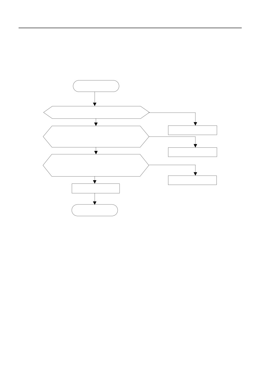
7.3 Troubleshooting Procedures
START
Please shut down the power
supply immediately to avoid
further expansion of the fault
Serious fault occurs, such as abnormal sound
upon power up and no display
NO
Seek for technical help
Identify the fault code per 4.4.4" Common
NO
Characters Displayed by LED" AND whether
the fault code can be Identified
YES
Seek for technical help
Find out the possible reasons and
countermeasures for the failure as per the
NO
above table, and whether this failure is
removed
YES
Seek for technical help
Fault reset
END
107
Chapter 8 Routine Repair and Maintenance
The application environment (such as temperature, humidity, dust and powder, wool, smoke and
oscillation), burning and wearing of internal devices and other factors may increase the possibilities of
inverter failure. To reduce the failures and prolong the service life the inverter, it needs to conduct routine
repair and periodic maintenance.
Note
1. Only the personnel receiving professional training can dismantle and replace the inverter components.
2. Prior to inspection and maintenance, please make sure that the power supply to the inverter has been
shut down for at least ten minutes or the CHARGER indictor is OFF, or there may be risks of electric
shock
3. Do not leave metal components and parts in the inverter, or it may damage the equipment.
8.1 Routine Maintenance
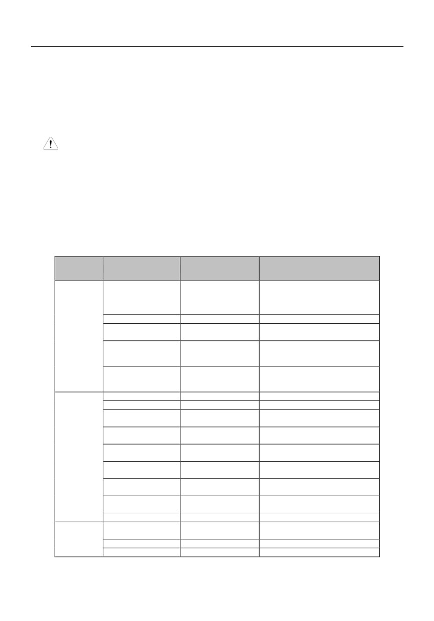
The inverter shall be used under the allowable conditions as recommended in this manual and its routine
maintenance shall be conducted as per the table below.
Item
Inspection Contents
Inspection Means
Criteria
-10 ~ +40ºC
Derated at 40 to 50ºC, and the rated
Temperature
Thermometer
output current shall be decreased by
1% for every temperature rise of 1ºC.
Humidity
Humidiometer
5 ~ 95%, no condensing
There are no dust, oil, water and
Operating
Dust, oil, water and drop
Visual check
drop.
Environment
3.5mm, 2~ 9Hz;
Vibration
Special test instrument
10m/s2,9~ 200Hz; 15m/s2,200~
500Hz
Special test instrument,
There are no abnormal smell and
Gas
smell check and visual
smoke.
check
Overheat
Special test instrument
Exhaust normal
Sound
Listen
There is no abnormal sound.
There are no abnormal smell and
Gas
Smell and visual check
smoke.
The physical appearance is kept
Physical appearance
Visual check
intact.
There are no fouling and wool that
Heatsink fan ventilation
Visual check
Inverter
block the air duct.
In the allowable operating range.
Input current
Amperemeter
Refer to the nameplate.
In the allowable operating range.
Input voltage
Voltmeter
Refer to the nameplate.
In the rated value range. It can be
Output current
Amperemeter
overloaded for a short while.
Output voltage
Voltmeter
In the rated value range.
Special test instrument
There are no overheat fault and
Overheat
and smell.
burning smell.
Motor
Sound
Listen
There is no abnormal sound.
Vibration
Special test instrument
There is no abnormal oscillation.
108
8.2 Periodic Maintenance
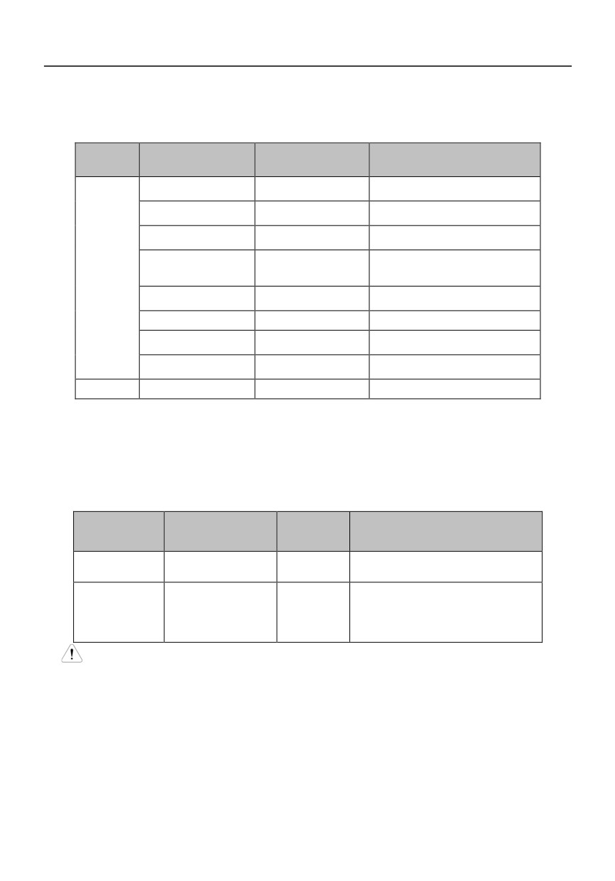
It needs to perform periodic inspection on the inverter once every three to six months according to the
application environment and work conditions.
Item
Inspection Contents
Inspection Means
Criteria
The screws are tightened and the
Main circuit terminal
Screwdriver/sleeve
cables are kept well.
The screws are tightened and the
PE terminal
Screwdriver/sleeve
cables are kept well.
The screws are tightened and the
Control circuit terminal
Screwdriver
cables are kept well.
Reliability of internal
Screwdriver and
connections and
Connection is firm and reliable.
hands
Inverter
connectors
Expansion card
Screwdriver and
Connection is firm and reliable.
connector
hands
Mounting screws
Screwdriver/sleeve
The screws are tightened.
Cleaning the dusts
Cleaner
There are no dusts and wools.
and powders
Internal foreign
Visual check
There are no foreign objects.
objects
Motor
Insulation test
500VDC megameter
Normal
8.3 Component Replacement
Different types of components have different service lives. The service lives of the components are
subject to the environment and application conditions. Better working environment may prolong the
service lives of the components. The cooling fan and electrolytic capacitor are vulnerable components
and shall be conducted routine inspection as per the table below. If any fault occurs, please conduct
immediate replacement.
Vulnerable
Damage Causes
Solutions
Items for Routine Inspection
Components
Bearing wear, blade
The fan blade has no cracks and rotates
Fan
Change
aging
normally. The screws are tightened.
There are no electrolyte leakage, color
Ambient temperature
change, crack and shell inflation. The
Electrolytic
is relatively high and
Change
safety valve is normal.
capacitor
electrolyte volatilizes.
Static capacity is equal to or higher than
the initial value times 0.85.
Note
When the inverter is stored for a long period of time, power connection test shall be conducted once
within two years and last at least five hours. It can use voltage regulator to gradually increase the
value to the rated value when power connection is performed.
8.4 Insulation Test
Since the inverter has undergone insulation test upon its ex-factory, the user shall not perform such test
as much as possible under general condition. If the test is unavoidable, please perform the test strictly
according to the following procedures, or it may damage the inverter.
109
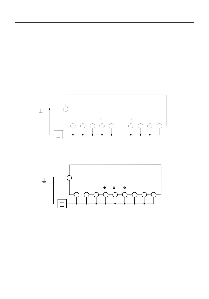
It shall perform dielectric test strictly, or it may damage the inverter. If the dielectric test is unavoidable,
please contact our company.
Main Circuit Insulation Test
Utilize 500VDC megameter to perform test under condition of main power shutdown;
Disconnect all the control board circuits to prevent the control circuits from connecting with the
test voltage. For the inverter with power level of HV390-4T11G/15L and HV390-4T15G/18.5L, it
must disconnect the terminal J1 on the drive board and the PE. For the inverter with power level
of HV390-4T18.5G/22L or above, it must disconnect three pieces of cables entry to the surge
absorption circuit. Pack the disconnected cable heads with insulating tapes properly;
The main circuit terminal shall be connected with public conducting wires:
PE
R
S
T
1
B
U
V
W
500 VDC
-
+
Fig:8−1 Main Circuit Insulation Test for HV390−0R4G1-2~HV390−2R2G1-2 、HV390−0R7G3~
HV390−015G3
PE
1
2
R
S
T
U
V
W
500 VDCLeading board
-
+
Fig:8−2 Main Circuit Insulation Test for HV390−018G3~HV390−400G3
Megameter voltage can only be imposed between the public conducting wire of the main circuit
and the PE terminal;
The normal indication value of the megameter is 20MΩ or above.
110
Appendix A Communication Protocol
1.Application range
Universal Variable Speed Drive connects with PLC or host computer via RS485 bus, which adopts single
master and multi-slave network structure.
2. Physical description
Interface: RS485 Bus, asynchronous, half-duplex
Each segment on the network bus can have up to 32 stations.
2.1. Data format
0:
8,N,2 for RTU
(MODBUS)(Default)
1:
8,E,1 for RTU
(MODBUS)
2:
8,O,1 for RTU
(MODBUS)
3:
7,N,2 for ASCII (MODBUS)
4:
7,E,1 for ASCII (MODBUS)
5:
7,O,1 for ASCII (MODBUS)
6:
8,N,1 free communication format
7:8,E,1 free communication format
8:
8,O,1 free communication format
2.2. Baud rate
Available baud rate: 1200, 2400, 4800, 9600, 19200, 38400
The default value is 9600BPS.
2.3. Communication address
Slave address range: 1~32
2.4. Communication mode
The drive works as slave, and PLC or host computer works as master. Communication of master is
polling, and the slave is in response mode.
2.5 Main function
111
a. Operation control:
Run, Stop, Jog start, Jog stop, free run to stop, Dec to Stop, fault reset, etc.
b. Operation monitor:
Running frequency, frequency setting, output voltage, output current, close loop feedback, close
loop reference, etc.
c. Operation of function code:
Read and write value of function code, which includes:
Present running frequency, present frequency setting, output voltage, current, close loop feedback,
close loop reference, etc.
3.Free communication Protocol
3.1 Data:
Character format:8,N, 1,8 bit data,one bit stop, no parity
8,E, 1,8 bit data,one bit stop, Even parity
8,O, 1,8 bit data,one bit stop, Odd parity
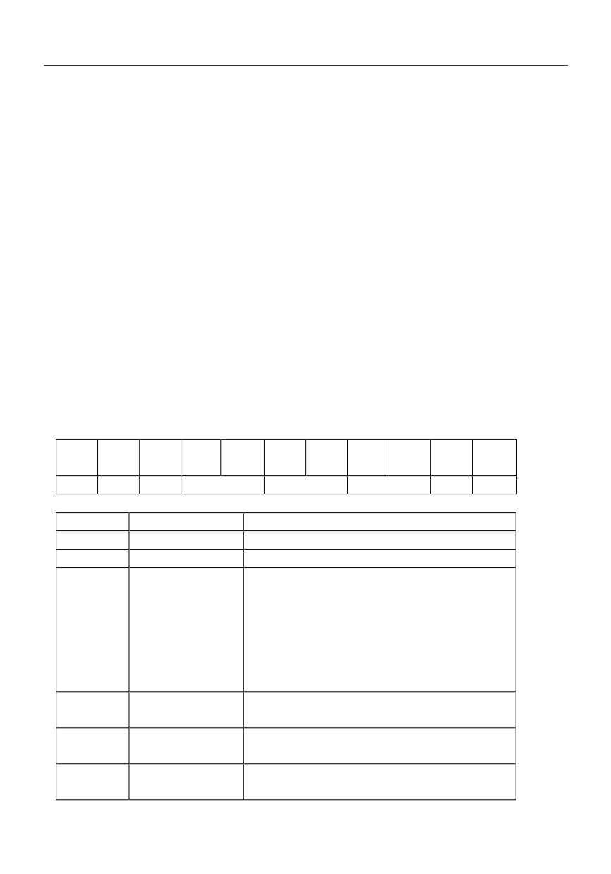
1.
A message from computer to inverter
BYT
BYT
BYT
BYT
BYT
BYT
BYT
BYT
BYT
BYT
BYT
E0
E1
E2
E3
E4
E5
E6
E7
E8
E9
E10
HD
AD
CD
OP
DT
CON
ED
SUM
Item
Byte Name
Detail
HD
Start byte
02H,one byte
AD
address
Inverter address,one byte,0 is broadcast address
CD
Parameter
R/W
One byte
command
0h:no operation
1h:read parameter from the inverter
10h:write parameter from the inverter,not store into
eerom
11h:write parameter from the inverter, store into
eerom
OP
Parameter number
Parameter number,two bytes,BYTE3 is lower byte,
BYTE4 is higher byte
DT
Parameter value
Parameter value,two bytes,BYTE5 is lower byte,
BYTE6 is higher byte
CON
Control word
Command word,two bytes,
BYTE7 is lower byte,BYTE8 is higher byte
112
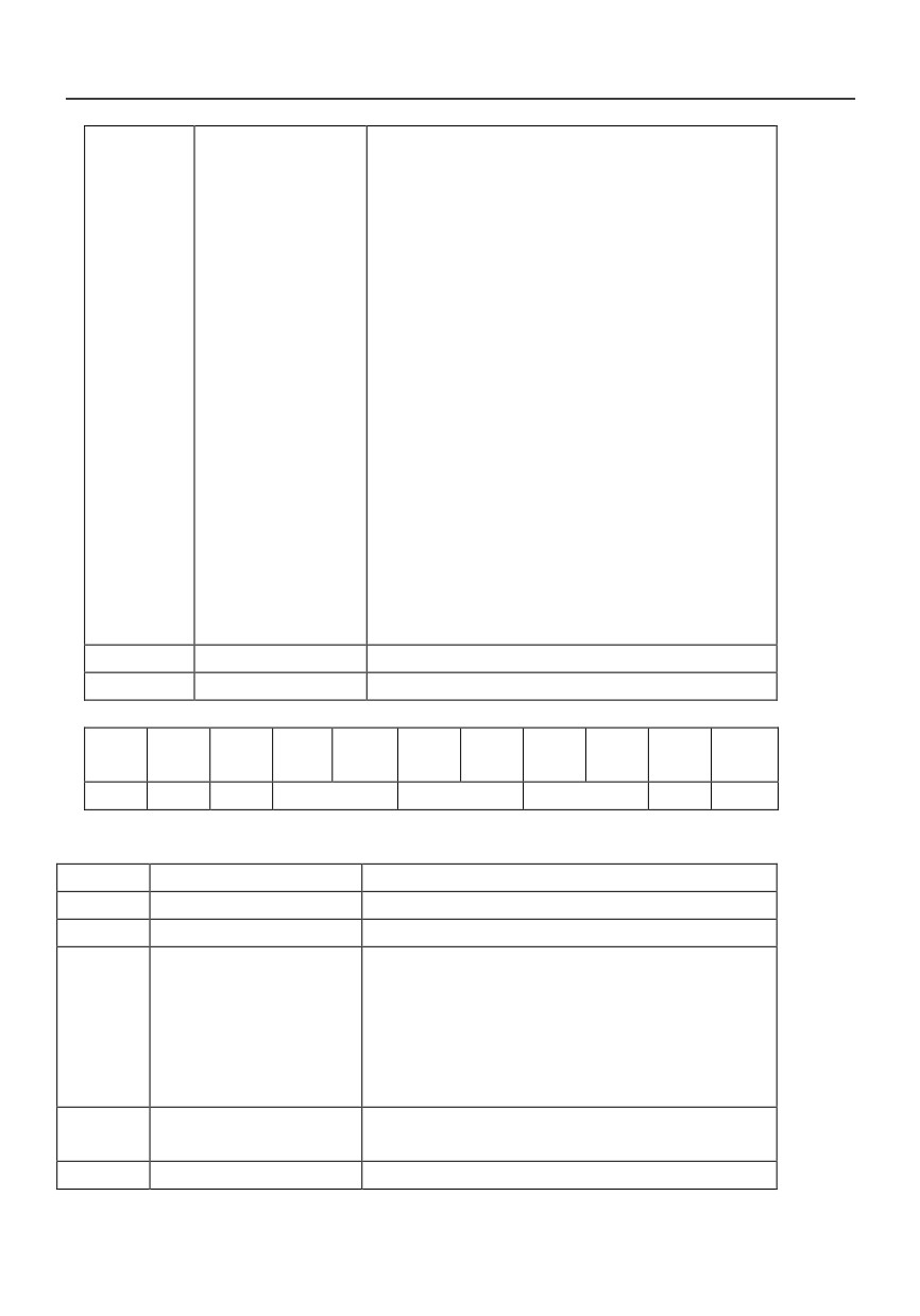
Bits of BYTE7 are defined as following:
bit0
=1,run command
=0,no command
bit1
=1,forward
=0,reverse
bit2
=1,forward jog start
=0,forward jog stop
bit3
=1,reverse jog start
=0,reverse jog stop
bit4
0-》1,Fault reset command
bit5 reserved
bit6
=1,free stop command
=0,no command
bit7
=1,decrease stop command
=0,no command
BYTE8 reserved
ED
End byte
A0H,one byte
SUM
Xor check
Xor form BYTE1 to BYTE9
2.
A message from the inverter to the computer
BYT
BYT
BYT
BYT
BYT
BYT
BYT
BYT
BYT
BYT
BYT
E0
E1
E2
E3
E4
E5
E6
E7
E8
E9
E10
HD
AD
CT
OP
DT
ST
ED
SUM
Item
Byte name
Detail
HD
Start byte
02H,one byte
IN
address
Inverter address,one byte,0 is broadcast address
CT
Parameter
operation
One bye
status
0:success
1:data received is exceed the range
2:address is exceed the range
3:data can not be modified while inverter is running
4:data is read only, can not be modified
OP
Parameter number
Parameter number,two bytes,BYTE3 is lower byte,
BYTE4 is higher byte
DT
Parameter value
Parameter value,two bytes,BYTE5 is lower byte,
113
BYTE6 is higher byte
ST
Status word
Status word of the inverter,two bytes,BYTE7 is lower
byte,BYTE8 is higher byte.
Bits of BYTE7 are defined as following:
bit0
=1,forward run
=0,reserse run
bit1
=1,inverter fault
=0,inverter no fault
bit2
=1,inverter running
=0,inverter stop
bit3
=1,data valid
=0,data invalid
bit4
=1,RS485 frequency setting
=0,loacl frequency setting
BYTE8 is the error code
ED
End byte
A0H,one byte
SUM
Xor check
Xor form BYTE1 to BYTE9
3.2 Application note
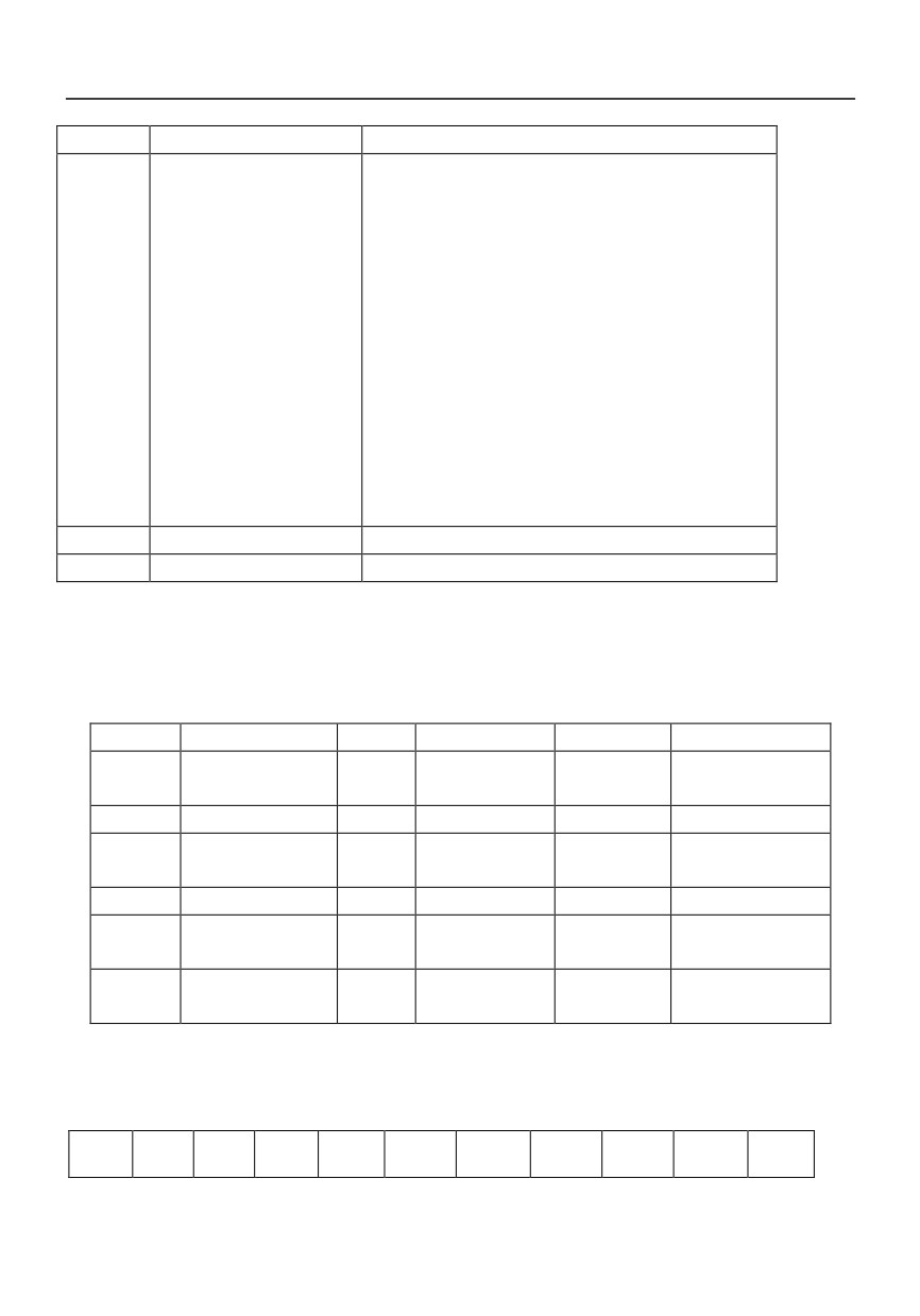
1.The OP,DT,ST,CON in communication protocol are two bytes. The address calculation of
OP is
converting the parameter address of the parameter list to HEX value. For example, 270 parameter, convert
to 10E in hex format; the lower byte of OP is 0eh;the higher byte of OP is 01h. Other parameters that are
not listed in parameter table are as following table.
1000H
Status word
1001H
Errorcode
1002 H
Control word
1003H
Frequency setting
1004H
Running
1005H
Output current
frequency
1006H
Output voltage
1007H
DC bus voltage
1008H
Overload rate
1009H
Preset line speed
100AH
Running line
100BH
Output torque
speed
100CH
PI reference
100DH
PI feedback
100EH
reserved
100FH
Analog input AI1
1010H
Analog input
1011H
I/O status
AI2
1012H
External counting
1013H
PID Set
value
2.For example, the computer set the set frequency of the inverter to 50.00Hz and send the run command to
the inverter. The address of the inverter is 01h. The OP of the setting frequency is 1003h in hex format. The
Setting frequency 50.00(5000) is convertedto 1388h in hex format.
A message from computer to the inverter:
02H
01H
10H
03H
10H
88H
13H
03H
00H
A0H
3AH
The inverter response:
114
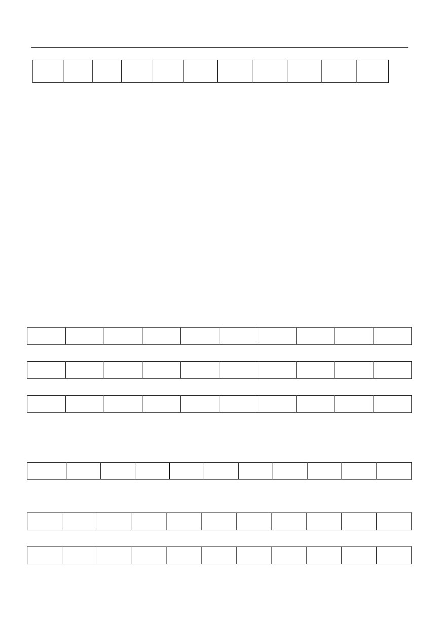
02H
01H
00H
03H
10H
88H
13H
1DH
00H
A0H
34H
3.3 Fault and troubleshooting
1. The protocol provide Start byte, end byte , xor check means to essure the correctness of the
communication.
2. There must be two bytes interval between two meaasge.
3. After the host issue a message, if the inverter does not response in seven bytes interval, the over
time fault of communication takes place.
4. MODBUS Protocol
4.1 Character format
1. ASCII
Communication adopts hexadecimal system, and the valid ASCII characters are: “0”…“9”,“A”…“F”,
which is expressed in hexadecimal format. Such as:
ASCII character: ‘0’‘1’‘2’‘3’‘4’‘5’‘6’‘7’‘8’‘9’‘A’‘B’‘C’‘D’‘E’‘F’
ASCII code (Hex):30H 31H 32H 33H 34H 35H 36H 37H 38H 39H
41H 42H 43H 44H 45H 46H
7,N,2
start
0
1
2
3
4
5
6
stop
stop
7,E,1
start
0
1
2
3
4
5
6
even
stop
7,O,1
start
0
1
2
3
4
5
6
odd
stop
2. RTU
8,N,2
start
0
1
2
3
4
5
6
7
stop
stop
8,E,1
start
0
1
2
3
4
5
6
7
even
stop
8,O,1
start
0
1
2
3
4
5
6
7
odd
stop
115
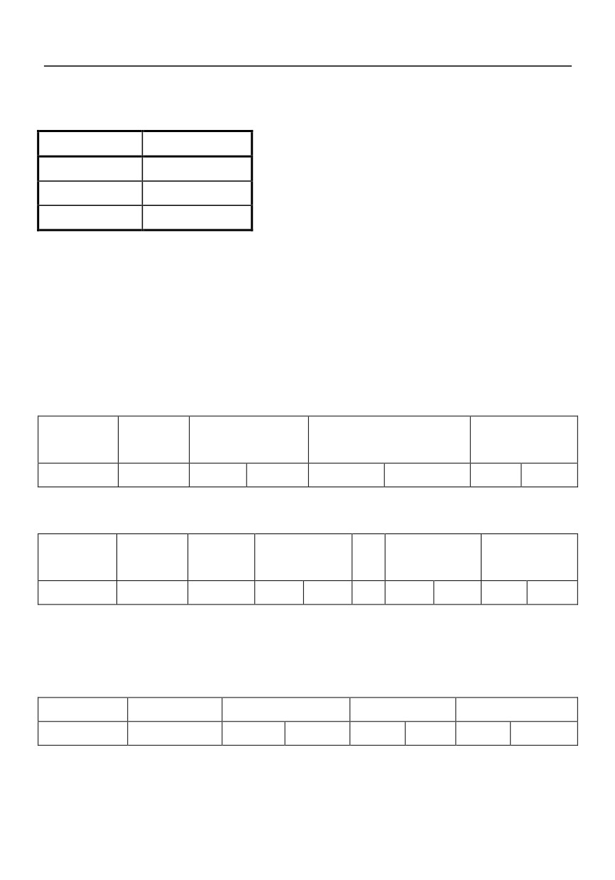
4.2 Function code
Function code
Description
03H
Read data
06H
Modify data
08H
Loop detection
2.Function code description
RTU
(1)Read data
Frame head and frame tail are used to ensure input time (without any information) larger than 10ms.
Each time, reading data should be less than 30 bytes.
Message format of master request:
Slave
Function
Start address of data
Data quantity
Redundancy
address
code
(Unit: word)
check
1 byte
03H
MSB
LSB
MSB
LSB
LSB
MSB
Message format of slave response:
Slave
Function
Data
Data 1
…
Data n
Redundancy
address
code
quantity
check
1 byte
03H
1 byte
MSB
LSB
…
MSB
LSB
LSB
MSB
MSB: high byte of double byte number; LSB: low byte of double byte number.
(2)Modify data
Message format of master request:
Slave address
Function code
Start address of data
Modified value
Redundancy check
1 byte
06H
MSB
LSB
MSB
LSB
LSB
MSB
Message format of slave response:
116
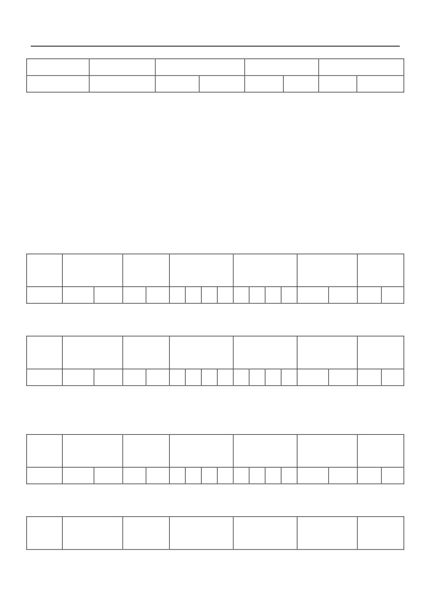
Slave address
Function code
Start address of data
Modified value
Redundancy check
1 byte
06H
MSB
LSB
MSB
LSB
LSB
MSB
(3) Loop detection
The command is used to test whether communication between main control equipment (usually PC
or PLC) and the drive is normal. After receiving data content, the drive will return it to main control
equipment without any modifying.
ASCII:
(1)
Read data:
Reading data should be less than 30 bytes at a time.
Message format of master request:
Frame
Function
Slave address
Data address
Data quantity
LRC
Frame tail
head
code
‘:’
MSB
LSB
‘0’
‘3’
4
3
2
1
4
3
2
1
MSB
LSB
CR
LF
Message format of slave response:
Frame
Function
Slave address
Data address
Data quantity
LRC
Frame tail
head
code
‘:’
MSB
LSB
‘0’
‘3’
4
3
2
1
4
3
2
1
MSB
LSB
CR
LF
(2) Modify data:
Message format of master request:
Frame
Function
Slave address
Data address
Modified value
LRC
Frame tail
head
code
‘:’
MSB
LSB
‘0’
‘6’
4
3
2
1
4
3
2
1
MSB
LSB
CR
LF
Message format of slave response:
Frame
Function
Slave address
Data address
Modified value
LRC
Frame tail
head
code
117
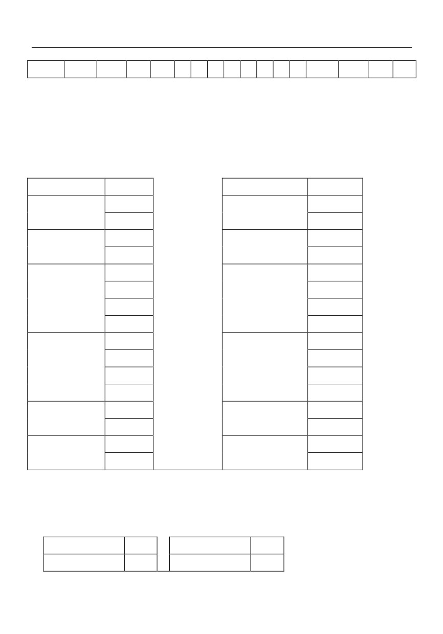
‘:’
MSB
LSB
‘0’
‘6’
4
3
2
1
4
3
2
1
MSB
LSB
CR
LF
3.Examples
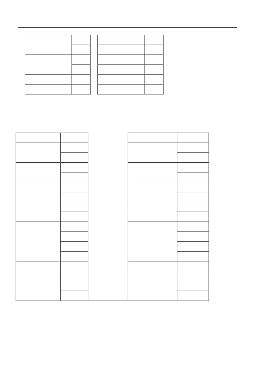
(1) Function code 03H: Read parameter data
ASCII mode:
Format of query message:
Format of response message:
Starting character
‘:’
Starting character
‘:’
Slave address
‘0’
Slave address
‘0’
‘1’
‘1’
Function code
‘0’
Function code
‘0’
‘3’
‘3’
Data address
‘0’
Data address
‘0’
‘2’
‘0’
‘0’
‘0’
‘0’
‘2’
Data
quantity
‘0’
Data content
‘1’
(word)
‘0’
‘5’
‘0’
‘5’
‘1’
‘9’
LRC
‘F’
LRC
‘8’
‘9’
‘C’
END
CR
END
CR
LF
LF
RTU mode:
Format of query message:
Format of response message:
Slave address
01H
Slave address
01H
Function code
03H
Function code
03H
118
Data address
02H
Data address
00H
00H
02H
Data quantity
00H
Data content
15H
(Word)
01H
59H
Low byte CRC
85H
Low byte CRC
2AH
High byte CRC
B2H
High byte CRC
A0H
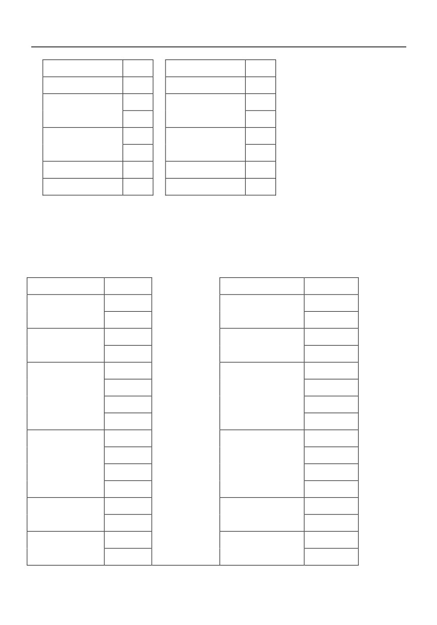
(2) Function code 06H: Write parameter data
ASCII mode:
Format of query message:
Format of response message:
Starting character
‘:’
Starting character
‘:’
Slave address
‘0’
Slave address
‘0’
‘1’
‘1’
Function code
‘0’
Function code
‘0’
‘6’
‘6’
Data address
‘0’
Data address
‘0’
‘1’
‘1’
‘0’
‘0’
‘0’
‘0’
Modified value
‘1’
Modified value
‘1’
‘7’
‘7’
‘7’
‘7’
‘0’
‘0’
LRC
‘7’
LRC
‘7’
‘1’
‘1’
END
CR
END
CR
LF
LF
RTU mode:
Format of query message:
Format of response message:
119
Slave address
01H
Slave address
01H
Function code
06H
Function code
06H
Data address
01H
Data address
01H
00H
00H
Modified value
17H
Modified value
17H
70H
70H
Low byte CRC
86H
Low byte CRC
86H
High byte CRC
22H
High byte CRC
22H
(3) Function code 08H: loop detection
ASCII mode:
Format of query message:
Format of response message:
Starting character
‘:’
Starting character
‘:’
Slave address
‘0’
Slave address
‘0’
‘1’
‘1’
Function code
‘0’
Function code
‘0’
‘8’
‘8’
Sub-function code
‘0’
Sub-function code
‘0’
‘0’
‘0’
‘0’
‘0’
‘0’
‘0’
Data content
‘1’
Data content
‘1’
‘2’
‘2’
‘A’
‘A’
‘B’
‘B’
LRC
‘3’
LRC
‘3’
‘A’
‘A’
END
CR
END
CR
LF
LF
120
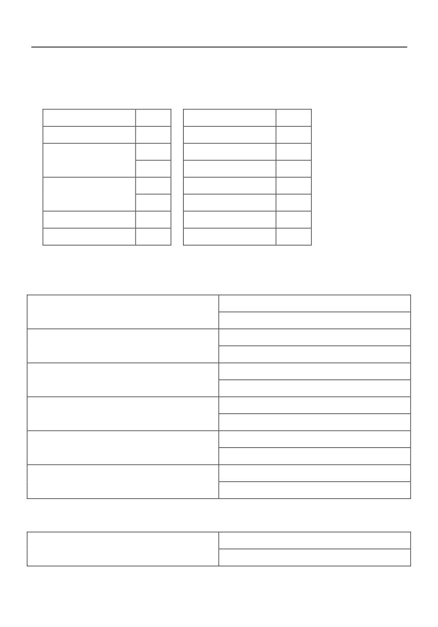
RTU mode:
Format of query message:
Format of response message:
Slave address
01H
Slave address
01H
Function code
08H
Function code
08H
Sub-function code
00H
Sub-function code
00H
00H
00H
Data content
12H
Data content
12H
ABH
ABH
Low byte CRC
ADH
Low byte CRC
ADH
High byte CRC
14H
High byte CRC
14H
4.4 Control word and status word
1. Information of status word (2 bytes)(1000H)
Bit0
=1, FWD
=0, REV
Bit1
=1, Drive failure
=0, No drive failure
Bit2
=1, Running state
=0, Stopping state
Bit3
=1, Modifying parameter valid
=0, Modifying parameter invalid
Bit4
=1, Frequency setting via RS485
=0, Local frequency setting
Bit5
=1, RS485 running control
=0, Local running control
2. Information of status word (2 bytes) (1002H)
Bit0
=1, Running command
=0, No running command
121
Bit1
=1, FWD
=0, REV
Bit2
=1, Jog FWD
=0, Jog FWD and stop
Bit3
=1, Jog REV
=0, Jog REV and stop
Bit4
=1, Fault reset command
=0, No fault reset command
Bit5
=1, Dec to stop command
=0, No Dec to stop command
Bit6
=1, Free run to stop
=0, No free run to stop
Bit7—bit15
Reserved
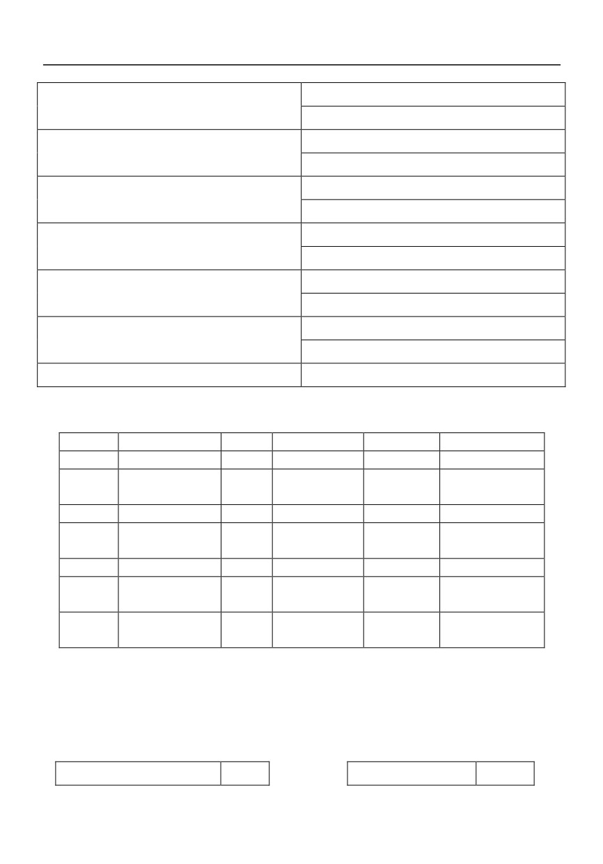
3. Parameter address
Addres
Name
Addres
Name
Addres
Name
1000H
Status word
1001H
Errorcode
1002 H
Control word
1003H
Frequency setting
1004H
Running
1005H
Output current
frequency
1006H
Output voltage
1007H
DC bus voltage
1008H
Overload rate
1009H
Preset line speed
100AH
Running line
100BH
Output torque
speed
100CH
PI reference
100DH
PI feedback
100EH
reserved
100FH
Analog input AI1
1010H
Analog input
1011H
I/O status
AI2
1012H
External counting
1013H
PID closed loop
value
setpoint
4.5 Fault and troubleshooting
If communication fault occurs, the drive will response fault code, and report function code or 80H to the
main control equipment.
For example:
ASCII mode:
RTU mode:
Starting character
‘:’
Slave address
01H
122
Slave address
‘0’
Function code
86H
‘1’
Fault code
02H
Function code
‘8’
Low byte CRC
C3H
‘6’
High byte CRC
A1H
Fault code
‘0’
‘2’
LRC
‘7’
‘7’
End character
CR
LF
Fault code:
01
Function code error:
Function code is invalid. In the protocol, valid function codes are: 03H, 06H or 08H.
02
Invalid data address:
Dataaddress is invalid
03
Invalid data setting
Data value is invalid.
04
Invalid command:
In current state, the drive can not execute this command.
09
Wrong CRC check
11 Reserved
12 Message characters of the command string is too short
13 Command string is too long, and reading string should be less than 72 characters.
14 Contains non-ASCII character, non-starting character or non-CR, LF end character.
Additional information
1. Function code conversion
If preset data is n, then sending data n = n×(1/increment) (Refer to function parameters table)
Convert data “n” into HEX number, which is 2 bytes.
123
2. ASCII mode LRC check
In the example above, LRC check:
01H+03H+02H+00H+00H+01H=07H, and it’s
complement=F9H.
3. RTU mode CRC check
LRC check is executed from slave address to data end character, and the operation rule is
shown as following:
Step 1: Load a 16-bit register with FFFFH. Call this the CRC register;
Step 2: Execute XOR operation with the first message command and the lower byte of
16-bit
CRC register,andput the result in the CRC register;
Step 3:
Shift the CRC register one bit to the right (toward the LSB), and fill the MSB with 0;
Step 4:
If the shifted bit is 0, save the new value of step 3 to CRC register; otherwise, execute
XOR operation with A001H and CRC register, and save the result in CRC register;
Step 5: Repeat step3~4 until 8 shifts have been performed.
Step 6:
Repeat step2~5 for the next 8-bit message command. Continue doing this until all
messages have been processed. The final content of
CRC register is the CRC value.
Note:
When the 16-bit CRC is transmitted in the message, the low-order byte will
betransmitted first, followed by the high-order byte.
124
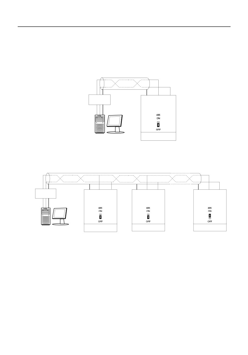
Appendix B Control Mode Setting Process
A inverter connected to a computer
Twisted pair with shielded
Converter
RS232-485
GND 485+ 485-
RS232 cable
Maximum 15
GND
meters
Computer
Site No.1
Appendix Fig.1A inverter connected to a computer
Several inverters connected to a computer
With shielded twisted pair
converter
RS232-485
GND 485+ 485-
GND 485+ 485-
GND 485+ 485-
RS232
cable
GND
Maximum
15 meters
······
Computer
Site No. 1
Site No. 2
Site No. n
The switch of terminal resistor of
the inverter at the most distant
place id turn to ON, start, the
internal 100Ω terminal compatible
resistance
Appendix Fig.2Several inverters connected to a computer
125
Product Feedback
Dear users:
Thank you for your interest and purchasing of HNC products!
HNC adheres to the "user-centric", based on customer demand, and offering full customer service to
enhance customer satisfaction.
We hope to learn about your present and future demand for HNC products as well as your valuable
feedback ofthe products. In order to help you get our service faster and more convenient, please visit our
company web site www.hncelectric.comfor information feedback.
1) Download the product manual you need.
2) Read and download all kinds of product technical information, such as operation instruction, product
specification, features, FAQ, etc.
3) Application cases.
4) Technical consultation, on-line feedback
5) Feedback product information and customer requirement information by e-mail.
6) Inquiry for the latest products, obtain various types of warranty and extend additional service, etc.
126
Warranty Agreement
1. The warranty period of the product is 18 months (refer to the barcode on the equipment). During the warranty
period, if the product fails or is damaged under the condition of normal use by following the instructions, HNC Electric
will be responsible for free maintenance.
2. Within the warranty period, maintenance will be charged for the damages caused by the following
reasons:
a. Improper use or repair/modification without prior permission
b. Fire, flood, abnormal voltage, other disasters and secondary disaster
c. Hardware damage caused by dropping or transportation after procurement
d. Improper operation
e. Trouble out of the equipment (for example, external device)
3. If there is any failure or damage to the product, please correctly fill out the Product Warranty Card in
detail.
4. The maintenance fee is charged according to the latest Maintenance Price List of HNC Electric.
5. The Product Warranty Card is not re-issued. Please keep the card and present it to the maintenance
personnel when asking for maintenance.
6. If there is any problem during the service, contact HNC Electric’s agent or HNC Electric directly.
7. This agreement shall be interpreted by HNC Electric Limited.
127