HV390 Series Frequency Inverter. User Manual (Version: 3.1.14) - page 3
PH.12
Running frequency
279
at last fault
PH.13
I/O state at last fault
280
PH.14
Total operating time
281
PH.15
Software version of
282
CPU Board
PH.16
Software version of
*
283
Keypad Board
54
Chapter 6 Detail Function Introduction
P0 Basic function parameters
P0.00 Reserved
P0.01 Running command selection
Setting range: 0, 1, 2
Select physical channel of inverter's running control command,common running commands include:
Start,Stop, FWD and REV;
0: Running command issued by keypad
Running command is issued by pressing thekeys on the keypad, such as
RUN,STOP/RESET,JOG, etc.
1: Running command issued by Externalterminals
Running command is issued by externalterminals, such as FWD, REV, JOGF
andJOGR(terminal function must be defined).
2: Running command issued by RS485 serialcommunication port
Running command can be issued throughinternal RS485 serial communication port byhost.
P0.02 Control mode
Setting range: 0~1
0:Sensorless vector control
That is no speed sensor vector control runningmode, which can be used for high performancevariable
speed general driving condition.
Note:
a. At the first running when vector control mode is selected, please perform motor
auto-tuning to get accurate parameters of motor. After auto-tuning, motor parameters
will be saved in the internal control board for control operation.
b.
To ensure high steady/dynamic control performance, user must set parameters of speed
controller correctly. For parameters setup and adjustment of speed controller, please
refer to explanation of P5 parameter group.
c.
If vector control mode is selected, one HV390 can only drive one motor. At this time,
motor capacity can be one level higher (full load is forbidden) or lower than that of the
inverter. Difference of capacity between inverter and motor should not be too large,
otherwise, the inverter’s control performance drops or drive system cannot operate
normally.
1:V/F control
When one inverter drives more than onemotor, if motor auto-tuning cannot beperformed or the motor's
parameters cannot beacquired through other methods, please selectV/F control mode.
P0.03 Main Frequency Source
Setting range: 0~9
HV390 series inverter has ten kinds offrequency setting mode.
0:Keyboard settings, set the current frequency by digital settings P0.11, adjust the inverterthrough the
keyboard up and down key
1: Reserved
2: External analog signal AI1(0~10V or 0~20mA)the voltage / current signal is determined by the J4
jumper selection
Use external analog signal AI1to set the running frequency
3:External analog signal AI2(0~10V or 0-20mA),the voltage / current signal is determined by the J5
jumper selection
4:up/down 1 setting
Present frequency is set by terminal defined by up/down function. Frequency setting is held when the
drive stops.
5:up/down
2 setting
Present frequency is set by terminal defined by up/down function. Frequency setting is the data of P0.11
55
when the drive stops.
6:Multi Frequency
You need to set relevant parameter of the P6 I/O and P2 ,When choose multi frequency operational mode
7:PID
You need to set relevant parameter of the PA and PID ,When choose PID operational mode
8:RS485 setting
Frequency setting is set by host computer via RS485 serial communication command.
9:Program running
When inverter begins running,Need to set P9 parameter.
P0.04 Main Frequency gain
Setting arrange:0.000~9.999
The main frequency is the product of the setting frequency selected by parameter P0.03 and this gain.
P0.05 Zero frequency source of
Setting arrange:0~3
multi-speed mode
0:Digital frequency of P0.11
1:Reserved
2:External analog signal:AI1
3:External analog signal:AI2
4:Communication given
P0.06 Auxiliary frequency setting
Setting arrange:0~4
HV390 series inverter has 4 kinds ofauxiliaryfrequency setting mode
0:External analog signal AI1(0~10Vor0~20mA)the voltage / current signal is determined by the J4
jumper selection
1:External analog signal AI2(0~10V or0~20mA)the voltage / current signal is determined by the J5
jumper selection
2:External analog signal AI1(0~10V or0~20mA)(+/- polarity)
3:External analog signal AI2(0~10V or0~20mA)(+/- polarity)
4:PID
5: Keyboard Increase and decrease key
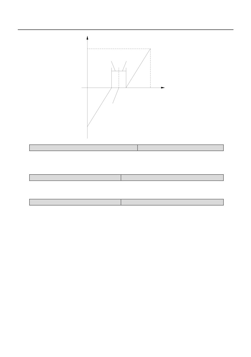
When P0.06=2,3, Polarity control of external analog AI1 and AI22 is shown in Fig. 6-1, With 5v as the
analog input, the center point is 0-5v negative adjustment and 5v-10v forward regulation.
56
50Hz
FWD
P7.10
P7.10
AI1
5V
10V
AI2
P7.01=50% P7.02=0Hz
OR P7.06=50% P7.07=0Hz
50Hz
REV
Fig6-1 Polarity control of external analog signal
P0.07 Auxiliary frequency range selection
Setting range:0~1
When the p0.09 is used to determine the range of the auxiliary frequency settings
0:Maximum output frequency
1:Main frequency
P0.08 Auxiliary frequency range
Setting range:0~100%
The auxiliary frequency is the product of the setting frequency selected by parameter P0.07 and this
gain.
P0.09 Setting Frequency selection
Setting range:0~9
Select the setting frequency source of the inverter.The frequency is given through a combination of the
frequency setting and the auxiliary frequency setting
0:Main frequency
The setting frequency source of the inverter is determined by the main frequency of the parameter of
P0.03.
1:Auxiliary frequency
The setting frequency source of the inverter is determined by the auxiliary frequency of the parameter of
P0.06.
2:Main frequency + Auxiliary frequency
3:Main frequency - Auxiliary frequency
4:switch between main frequency and auxiliary frequency
The setting frequency source of the inverter can be switched between the main frequency and auxiliary
frequency with the external terminal defined by P6 Group parameter.
5:switch between Main frequency and (Main frequency + Auxiliary frequency)
The setting frequency source of the inverter can be switched between the main frequency and (Main
57
frequency + Auxiliary frequency) with the external terminal defined by P6 Group parameter.
6:switch between Main frequency and (Main frequency - Auxiliary frequency)
The setting frequency source of the inverter can be switched between the main frequency and (Main
frequency - Auxiliary frequency) with the external terminal defined by P6 Group parameter.
7:MAX(Main frequency,Auxiliary frequency)
The setting frequency source of the inverter is maxium of main frequency and auxiliary frequency
8:MIN(Main frequency,Auxiliary frequency)
The setting frequency source of the inverter is minium of main frequency and auxiliary frequency
9:Traverse operation
The setting frequency source of the inverter is determined by traverse operation mode defined by function
code Pb parameter group.
P0.10 Keyboard and up/down
setting store
Setting range:0、1
selection
0:Store
The initial frequency setting value is the value of parameter P0.11. It can be changed by the terminal
defined with function UP/DOWN. When the inverter is power off, the current frequency setting value is
stored.
1:Not Store
The initial frequency setting value is the value of parameter P0.11. It can be changed by the terminal
defined with function UP/DOWN. When the inverter is power off, the current frequency setting value is
notstored.
P0.11digital frequency setting
Setting range: 0.00~High frequency limit
If digital frequency setting via panel is selected, the value of parameter, will be the present preset
frequency.
P0.12 Rotating direction
Setting range: 0, 1
If panel control mode is selected, select the relationship between inverter'sactual output direction and
the direction of control command.
0: Same with control command;
1: Opposite to control command
P0.13Maximum output frequency
Setting range: 50Hz~600.0Hz
P0.14 High frequency limit
Setting range:
0.00Hz~ Maximum output
frequency
P0.15 Low frequency limit
Setting range: 0.00Hz~Upper frequency limit
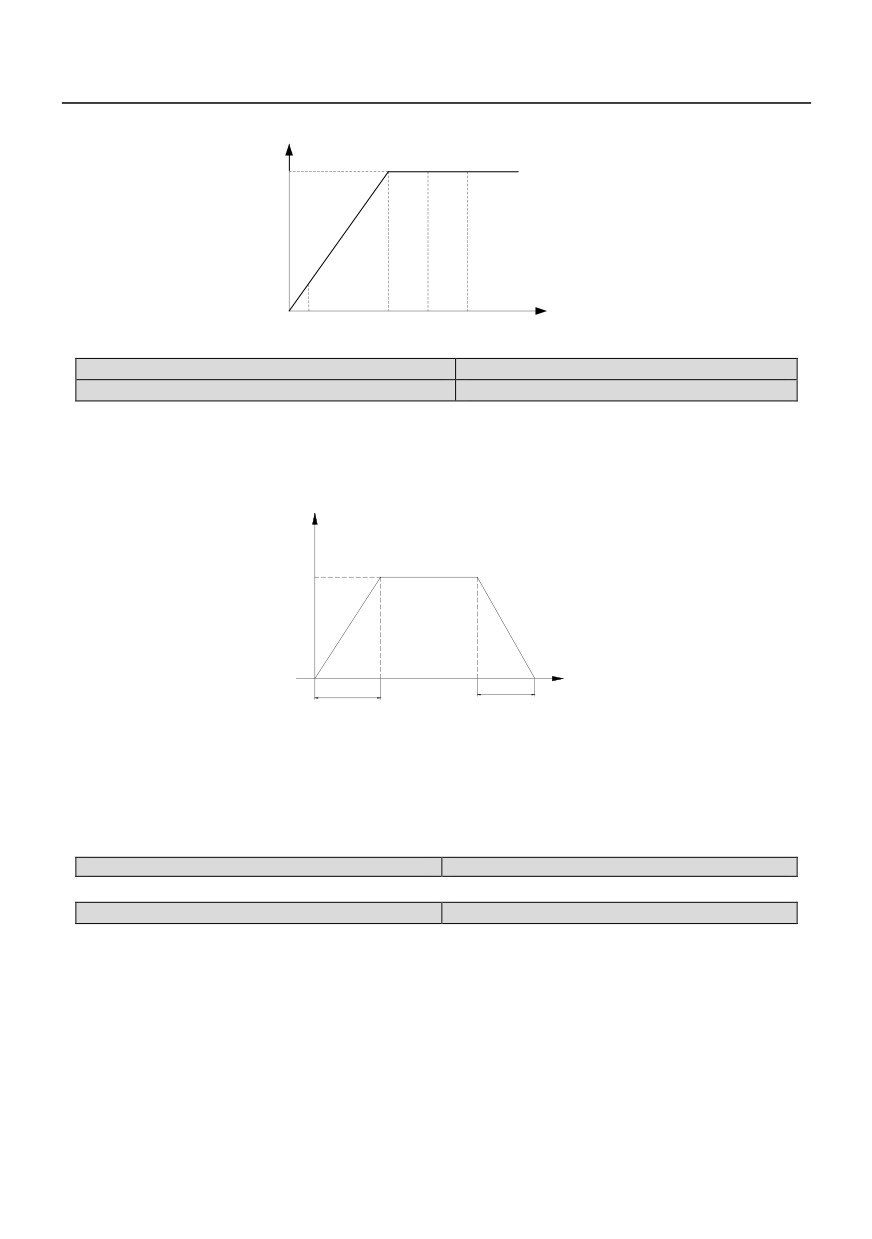
The maximum output frequency is themaximum frequency which the inverter is ableto output, shown
in Fig. 6-2 as Fmax;
High frequency limit is the maximum frequency which the user is allowed to set, shown in Fig. 6-2 as
Fh;
Low frequency limit is the minimum frequencywhich the user is allowed to set, shown inFig. 6-2 as FL;
Fb in Fig.6-2 is basic running frequency, whichis defined as the lowest output frequency whenthe
inverter outputs the highest voltage in V/Fcontrol mode.
58
Output voltage
Vmax
Output
frequency
fL
fb
fH
fmax
Fig.6-2 Frequency limits definition
P0.16 Acc time 1
Setting range: 0.1~3600s
P0.17 Dec time 1
Setting range: 0.1~3600s
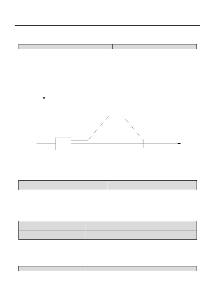
Acc time means the time during which theinverter output from zero frequency to the maximum output
frequency, shown in Fig. 6-3 asT1.
Dec time means the time during which theinverter outputs from the maximum outputfrequency to zero
frequency, shown in Fig. 6-3 as T2.
output frequency
Fmax
Time
T1
T2
Fig 6-3 Definition of Acc/Dec time
Factory setting of Acc/Dec time: Acc/Dec time 1(P0.16、P0.17)。
Other Acc/Dec time must be selected throughcontrol terminals according to differentgroups(Please
refer to P2 Parameter group)。
When program is running, selection of Acc/Dec timegroup is setup in function code (Please refer to P9
Parameter group).
P0.18 reserved
Setting range: 0, 1
P0.19 Parameter initialization
Setting range:0~3
0: No operation
Inverter is in normal parameter read/write state.
1: Clear fault information
The fault information clearing operation willclear all the memorized parameters stored inthe function
codes betweenPH.06~PH.13
2: Recover factory setting
Setup F0.19 to 2 and confirm, inverter willrecover all the parameters between P0~P2 and P4~PH to the
defaultfactory setting value.
All the setting values of P3 Parameter groupwill not be influenced when factory settingvalue is restored.
3: Parameter locking
When set P0.19 to 3, parameter locking function is enabled. Except this parameter, all other
59
parameters are read only and can not be modified.
P1 Auxiliary function parameters 1
P1.00 start mode
Setting range: 0~1
0: Start from starting frequency
When inverter begins running, it starts fromstarting frequency (P1.01) and runs for the presettime
(P1.02) at this frequencyaccording to thesetting values of P1.01 and P1.02; then itenters normal Acc mode
according to presetAcc time and Acc/Dec mode parameters, atlast it accelerates to preset frequency.
1: Brake first then start from starting frequency
When inverter begins running, it starts DCinjection braking process according to thepreset DC injection
braking voltage and timedefined in P1.03 and P1.04. It starts from starting frequency, and runs for the preset
time at thisfrequency; and then enters normal Acc modeaccording to preset Acc time and Acc/Decmode
parameters, and at last accelerates topreset frequency. The process is shown inFig. 6-4.
Output frequency
Acc process
Dec process
Start
Stop DC braking
Frequency
Start frequency
P1.01
Start DC
P1.06
Run time
stop
braking
Start
Frequency
Hold time
P1.02
Fig. 6-4 Start mode 1 (FWD, REV, Stop and RUN) diagram
P1.01 Starting frequency
Setting range: 0.50~20.00Hz
P1.02 Hold time of starting frequency
Setting range: 0.00~60.0s
Start frequency: It is the initial frequency whenthe inverter starts from zero frequency, which is shown in
Fig. 6-4.
In the Acc and Start process, if the presetfrequency is lower than the start frequency,inverter's output
frequency becomes zero;
Start frequency holding time: the running timeat start frequency in Acc/Start process, which is shownin
Fig. 6-4.
P1.03 DC injection brakingtime at
Setting range: 0.00~60.0s
start
P1.04 DCinjection braking current
Setting range:0.0~100.0%(inverter rated currente)
at start
DC braking time at start:holding time for outputDC injection braking current when the inverteris in start
process.
If DC injection braking time at start is set to 0.0second, DC injection braking function isdisabled.
DC braking current at start:percentage ofbraking voltage when the inverter starts in DCinjection
braking process.
P1.05 Stop mode selection
Setting range: 0, 1, 2
0: Dec-to-stop mode 1
When the inverter receives stop command, itlowers its output frequency and decelerates tostop
60
according to the preset Dec time. During Dec process, for inverter with braking resistor or unit, it will enter
dynamic braking.
1: Dec-to-stop mode 2
After the inverter receives stop command, itlowers its output frequency and decelerates tostop
according to the preset Dec time. During Dec process, when output frequency is equal to the frequency set
by P1.06, the inverter starts DC braking according to the DC braking time and voltage defined by P1.07 and
P1.08.
2: Free run to stop
After the inverter receives the stop command,it stops its output immediately; the motor will decelerate to
stop according to its inertia.
P1.06Initial frequency ofDC injection braking
Setting rang: 0.00~20.00Hz
Initial frequency of DC injection braking: It isthe frequency when the inverter's outputfrequency is
decreased to zero along the Deccurve in Dec-to-stop process, which is shown in Fig. 6-4.
In the process of Dec-to-stop, when the presetfrequency is lower than the initial frequency ofStop DC
injection braking, the inverter’s output frequency is decreased to zero.
If the running condition has no strictrequirements for braking, the initial frequencyof DC injection
braking should be set as low aspossible.
P1.07DC injectionbraking time
Setting range: 0.0, 0.1~60.0s
P1.08 DC injection braking current
Setting range: 0.0~100.0% (inverter’s rated current)
DC injection braking time:the time formaintaining output DC injection braking in inverter's stopping
process.
DC injection braking current: percentage ofbraking voltage when the inverter stops in DCinjection
braking mode.
When the DC injection braking time is set to0 second., the DC injection braking function isdisabled.
P1.09 Acc/Dec modeselection
Setting range: 0, 1
Acc/Dec modes 0 and 1 are valid in Start,Stop, FWD/REV, Acc and Dec process.
0: linear mode
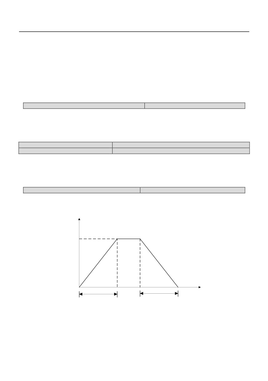
In Acc/Dec process, the relationship betweenoutput frequency and Acc/Dec time is linear.The output
frequency increases or decreasesat the constant slope as shown in Fig. 6-5.
Output
frequency
Fmax
Running
time
T1
T2
Fig. 6-5 linear Acc/Dec
1: S curve mode (reserved)
In Acc/Dec process, the relationship betweenoutput frequency and Acc/Dec time isnonlinear. The
output frequency increases ordecreases according to the S curve shown inFig. 6-6.
61
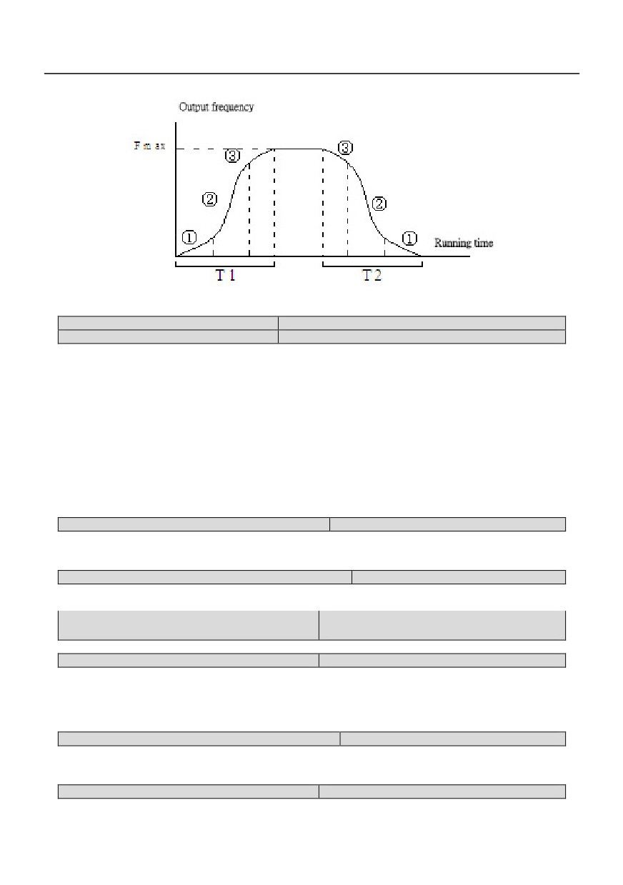
Fig. 6-6 S curve Acc/Dec
P1.10 Time of S curve’ s startpart
Setting range:10.0 ~ 50.0 %(Acc/Dec time)
P1.11 Time of S curve’ srising part
Setting range:10.0 ~ 80.0 %(Acc/Dec time)
The function codes of P1.10 and P1.11 definethe Acc/Dec parameters of S curve.
S curve start time is shown in Fig. 6-6 as ①,which is the stage when the slope of outputfrequency
rises gradually.
S curve rise time is shown in Fig. 6-6 as ②,which is the stage when the slope of outputfrequency
maintains phase.
S curve end time is shown in Fig.6-6 as ③,which is the stage when the slope of outputfrequency
decreases to zero.
Note:
1. Limit of setting value:S curve start time + Scurve rise time≤90% (Acc/Dec time).
2. In Acc/Dec Process, the parameters of Scurve are set in symmetry.
P1.12 Restart after powerfailure
Setting range: 0, 1
0: Disabled;
1:Enabled; Function of restarting after power failure isenabled when the power supply recovers.
P1.13 Delay time forrestarting after power failure
Setting range: 0.0~20.0s
When the power recovers from failures, thetime before the inverter restarts is the delaytime.
This time is set according to the time neededby other equipment to recover when the power supply recovers.
P1.14 dynamic braking start voltage
380V voltage level Setting range:630~710V
220V voltage level Setting range:350~380V
Setting the start voltage of dynamic braking.
P1.15Rate of dynamic braking
Setting range: 0.0 ~100.0%
Define duty cycle of dynamic braking.
0: No dynamic braking
1%~100%: In process of dynamic braking, percentage of valid braking time to carrier cycle, user can
modify this value if necessary.
P1.16Start frequency lower than frequency limit
Setting range:0, 1,2
0:when preset frequency is lower than low frequency limit, the inverter will not start;
1:when preset frequency is lower than low frequency limit, the inverter will start at low frequency limit;
2:When preset frequency is lower than frequency limit, the inverter stop.
P1.17 M key function
0:No operation;
62
1:forward rotation
2:reverse rotation
P1.18 Stop/reset Key function
Setting range:0、1、2
This parameter decides the “stop” function of STOP/RESET key of the keypad in different command
source. The ”Reset”function is usable in all command source.
0:action on keypad control mode
1:action on both keypad and External terminal
2:action on both keypad and communication
P1.19Fan control function
Setting arrange:0、1
0:Cooling fan always runs after power on
1:Cooling fan stops fan after inverter stop running
P2 Auxiliary function parameters 2
P2.00 Acc time2
Setting arrange:0.1~3600s
P2.01 Dec time2
Setting arrange:0.1~3600s
P2.02 Acc time3
Setting arrange:0.1~3600s
P2.03 Dec time3
Setting arrange:0.1~3600s
P2.04 Acc time4
Setting arrange:0.1~3600s
P2.05 Dec time4
Setting arrange:0.1~3600s
Four Acc/Dec times are defined as following:
Phases of Acc/Dec time
1
2
3
4
DI4
OFF
ON
OFF
ON
Terminal state
DI5
OFF
OFF
ON
ON
As shown in the table above, in normal operation condition, Acc/Dec time 1 is the default setting (both
terminals DI4, DI5 are OFF, and Acc/Dec time 1 and 2 are defined by terminal DI4 and DI5 respectively).
P2.06 Jog Acc time 1
Setting range: 0.1~20.0s
P2.07 Jog Dec time 1
Setting range: 0.1~20.0s
P2.08Jog frequency
Setting range: 0.5~60.00Hz
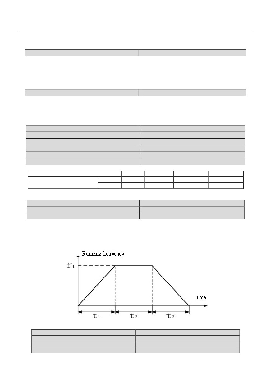
P2.06~P2.08 define the jog running parameters, which is shown in Fig. 6-7.
In Fig. 6-7, f1 is Jog running frequency (P2.08), t1 is Jog Acc time (P2.06), t3 is Jog Dec time (P2.07),
and t2 is the Jog running time.
Jog running command can be issued throughpanel,control terminal or host computer.
Fig. 6-7 Jog running parameters
P2.09 Multi-frequency 1
Setting range: 0~600.0Hz
P2.10 Multi-frequency 2
Setting range: 0~600.0Hz
P2.11 Multi-frequency 3
Setting range: 0~600.0Hz
P2.12 Multi-frequency 4
Setting range: 0~600.0Hz
63
P2.13 Multi-frequency 5
Setting range: 0~600.0Hz
P2.14 Multi-frequency 6
Setting range: 0~600.0Hz
P2.15 Multi-frequency 7
Setting range: 0~600.0Hz
P2.16 Multi-frequency 8
Setting range: 0~600.0Hz
P2.17 Multi-frequency 9
Setting range: 0~600.0Hz
P2.18 Multi-frequency 10
Setting range: 0~600.0Hz
P2.19 Multi-frequency 11
Setting range: 0~600.0Hz
P2.20 Multi-frequency 12
Setting range: 0~600.0Hz
P2.21 Multi-frequency 13
Setting range: 0~600.0Hz
P2.22 Multi-frequency 14
Setting range: 0~600.0Hz
P2.23 Multi-frequency 15
Setting range: 0~600.0Hz
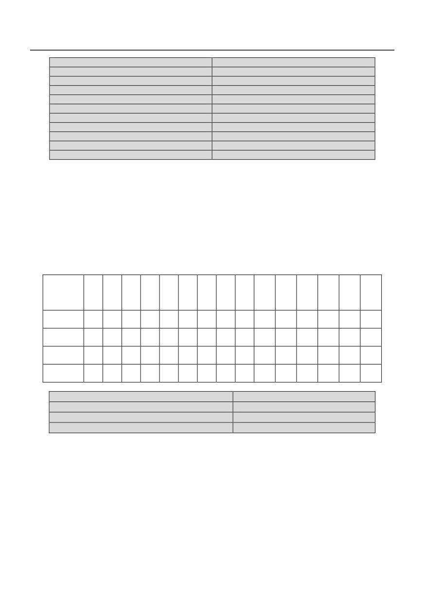
Multi-frequency/speed is set in P2.09 ~ P2.23, which can be used in multi-speed running and
programming state.
There are 15 multi-frequency operation modes, which can be selected through control terminals.
Assumption:
“1 (ON)” means that control terminal is connected;
“0 (OFF)” means that control terminal is disconnected.
If control terminals of multi-frequency are not set, or all of them are in OFF position, frequency setting
is determined by function code P0.05;
If certain control terminal of multi-frequency is not in OFF position, frequency setting is determined by
function code P2.09~P2.23;
If multi-frequency operation is selected, Starting/stopping the drive is determined by control mode
selection P0.01.
Freque
ncy
1
2
3
4
5
6
7
8
9
10
11
12
13
14
15
X
X
X
X
X
X
X
X
X
X
X
X
X
X
X
Terminal
Terminal
1
0
1
0
1
0
1
0
1
0
1
0
1
0
1
1
Terminal
0
1
1
0
0
1
1
0
0
1
1
0
0
1
1
2
Terminal
0
0
0
1
1
1
1
0
0
0
0
1
1
1
1
3
Terminal
0
0
0
0
0
0
0
1
1
1
1
1
1
1
1
4
P2.24Jump frequency 1
Setting range: 0~600.0Hz
P2.25 Jump frequency 2
Setting range:0~600.0Hz
P2.26Jump frequency 3
Setting range:0~600.0Hz
P2.27Jump frequency range
Setting range:0~20.00Hz
Jump frequency is set to prevent the outputfrequency of inverter from meeting themechanical
resonant point of load.
In Jump frequency parameters, set thesystem's mechanical resonant centralfrequency, at most three
frequency values canbe setup, shown in Fig.6-8.
64

Output
frequency
Jump frequency
Jump range
3
Jump range
Jump frequency 2
Jump range
Jump frequency 1
Frequency setup signal
Fig. 6-8 Jump frequency and its range
P2.28FWD/REV dead time
Setting range: 0.1~3600s
FWD/REV dead time: the waiting and holdingtime before the motor changes its rotating direction after
the inverter's output frequency isdecreased to zero. It is the time taken by themotor to change its rotating
direction when theinverter receives REV command during itsrunning process. The time is shown in Fig. 6-9
as T0.
Running frequency
Running time
TO
Fig. 6-9 FWD/REV dead time
P2.29REV prohibited
Setting range: 0, 1
When P2.29=0, this function is disabled. In this case, terminal F/R=OFF, Run FWD; terminal F/R=ON,
Run Rev;
When P2.29=1, this function is enabled. In this case, terminal F/R signal is invaid. Mtor can only run
forward, and switching between FWD/REV is not available.
Running mode of routine program is independent of this function.
In traverse operation mode, both FWD and REV running are allowable, but switching between
FWD/REV is prohibited. Setting FWD/REV direction may not be same as actual direction, which can be
defined by changing phase sequence of the output.
P2.30Carrier frequency adjustment
Setting range:2.0~12.0KHz
65
Carrier wave frequency can be continuously adjusted within 2.0~12.0KHz.
This function is mainly used to improve system performance, and reduce noise and vibration.Since HV390
series adopts IGBT as power devices, carrier frequency can be higher. Increasing carrier frequency can
bring following benefits: better current waveform, lower noise, which is especially suitable for applications
that need low noise. However, with the increase of carrier frequency, it also brings some disadvantages,
such as increase of power loss on switching devices, overheat, low efficiency, etc. Since high frequency
carrier produces severeradio interference, please install filter for application with high requirement on EMI.
At the same time, capacitive leakage current increases, and the wrong action of leakage protector and over
current may happen.
Decreasing carrier frequency, the contrary is the case. Motor noise will increase in lower carrier frequency.
Influence of carrier frequency is different for various motors. Therefore, optimalcarrier frequency should be
selected according to practical situation. In fact, with the increase of motor capacity, carrier frequency should
decrease. For motor capacity above 37 kW, 2KHz carrier frequency is recommended.
P2.31Zero frequency threshold
Setting range: 0~600.0Hz
P2.32Zero frequency hysteresis
Setting range: 0~600.0Hz
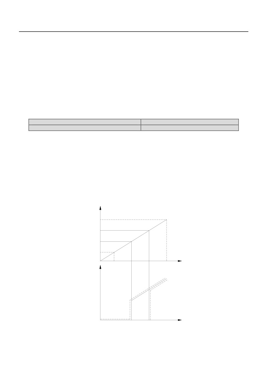
The above two parameters are to set zerofrequency hysteresis control.
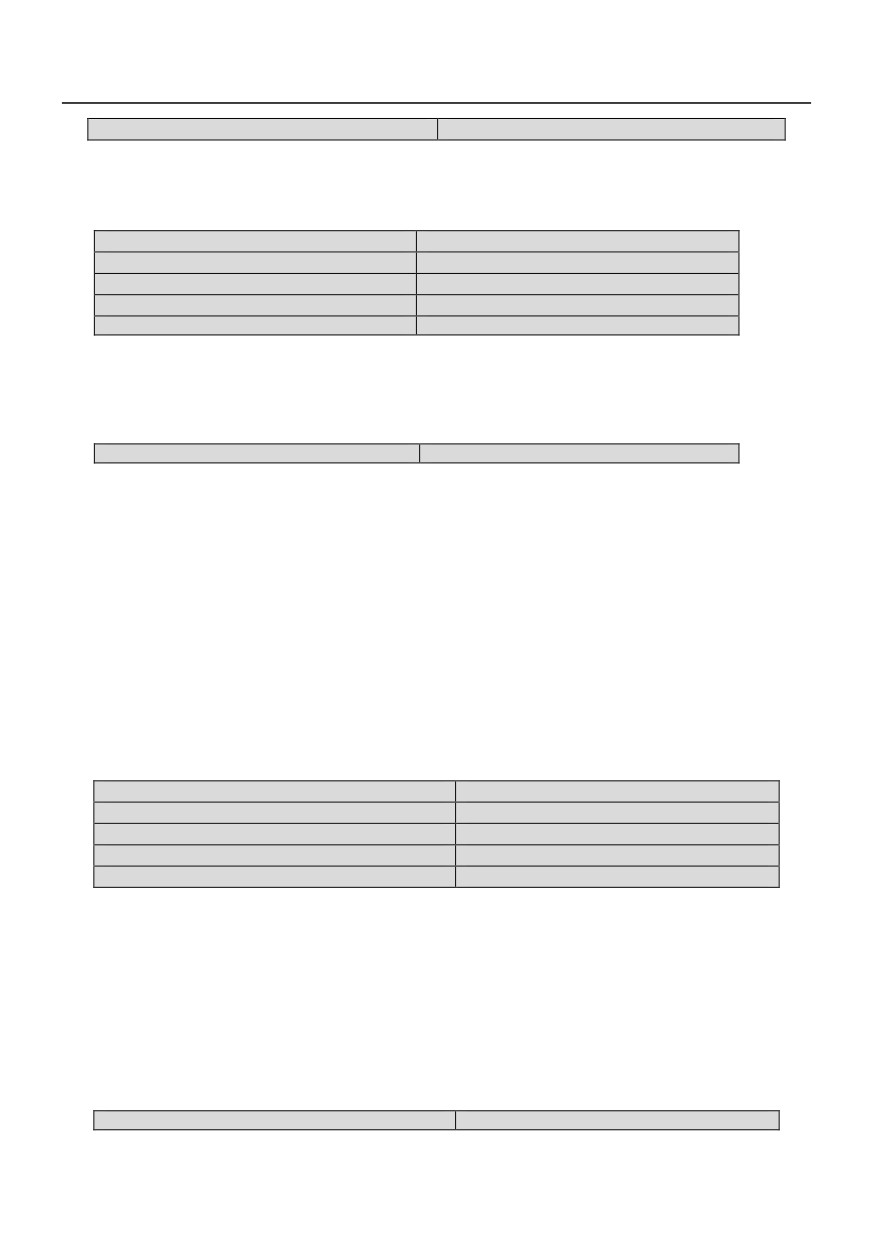
Take analog input AI1 for example, see Fig.6-10:
Startup process:
When the Run command is issued, only afterAI1voltage arrives or exceeds VS-b, does the drive start
andaccelerate to the preset frequency in defined Acc time.
Stop process:
During Dec process, when AI1voltage reduces to VS-b, thedrive will not stop until it reaches VS-a and
thecorresponding frequency becomes fa, where fa isthe threshold of zero frequency defined by P2.31, and
fb, fa is defined by P2.32.
This function can realize dormancy to saveenergy, in this way, frequent start and stop atthreshold frequency
can be avoided.
AI1 Input voltage
FWD
VS-b
VS-a
Vmin
Output
frequency
Fmin
Fmax
Operating
frequency
Setting
frequency
0
Fa
Fb
fa: Zero frequency threshold
fb: fa + Zero frequency hysteresis
Fig. 6-10 Zero Frequency Hysteresis
66
P2.33Droop control
Setting range:0.00~10.00Hz
When several inverter drives one load, the load of indivial inverter is different due to speed difference. The
inverter with higher speed drives more load. This parameter can decrease the speed when the load is
increased and equalizes the load of inverters.
P3 Motor parameters
P3.00 Motor rated power
Setting range:0.4~999.9kW
P3.01 Motor rated voltage
Setting range:0~440V
P3.02 Motor rated current
Setting range:0.1~999.9A
P3.03 Motor rated frequency
Setting range:1.00~600.0Hz
P3.04 Motor rated speed
Setting range: 1~999 rpm
Note:
In order to ensure motor tuning, please set nameplate parameter of the motor correctly.
In order to ensure high control performance, the motor capacity should match that of the drive.Generally
the motor’s power is allowed to be one grade higher or lower that of the drive.
P3.05 Motor auto-tuning
Setting range: 0, 1,2
Note: Before tuning, the parameters on thenameplate of the motor must be inputcorrectly (F3.00~F3.04).
0:No operation
1:static autotuning
If the load can not be unconnected from motor, user can adopt static autotuning. First set F3.05 to 1,
after confirmation, thenpress the RUN key on the Keypad, inverter willperform static auto-tuning functions.
2:overall auto- tuning
First set F3.05 to 2, after confirmation, thenpress the RUN key on the Keypad, inverter willperform overall
auto-tuning functions. The overall auto- tuning includes static autotuning and spinning autotuning and the
load must be unconnected form the motor.
Note:
a.
If over-current or over-voltage fault occurs during tuning process, user can adjust Add/Dec time
(P0.16, P0.17) and torque boost (P4.07);
b.
Do not start tuning with load on motor;
c.
Make sure the motor is in stopping status before tuning, otherwise, the tuning can not be
performed normally;
d.
Motor auto-tuning can only be performed in keypad control mode(P0.01=0).
P3.06 Stator resistance
Setting range:0.001-20.00%
P3.07 Rotor resistance
Setting range:0.001-20.00%
P3.08 Self inductance
Setting range:1.000~9.999
P3.09 leakage inductance
Setting range:0.001~1.000
P3.10Exciting current with no load
Setting range:0.0~999.9A
Factory settings of P3.06~F3.10 are the parameters of motor that rated power matches the
inverter. If user already knows the motor's parameters, just input the motor parameters directly.
However, after successfully performing motor auto-tuning, value of P3.06~P3.10 will be updated
automatically.
Resistance and inductance are the relative value of the nomial motor parameters.
Resistance value=(real Resistance value)*(1.732*I)/V*100%;
Inductance value=(real Inductance value)*2*3.14*P*(1.732*I)/V;
In above formular,V is motor rated voltage defined by P3.01 ; I is motor rated current defined by P3.02 ;
Pis the motor rated frequency defined by P3.03.
These parameters are reference parameters for vector control, which will affect control performance
directly.
P3.11 Reserved
67
P4 Dedicatd function for V/F control
P4.00 V/F curve control mode
Setting range:0~4
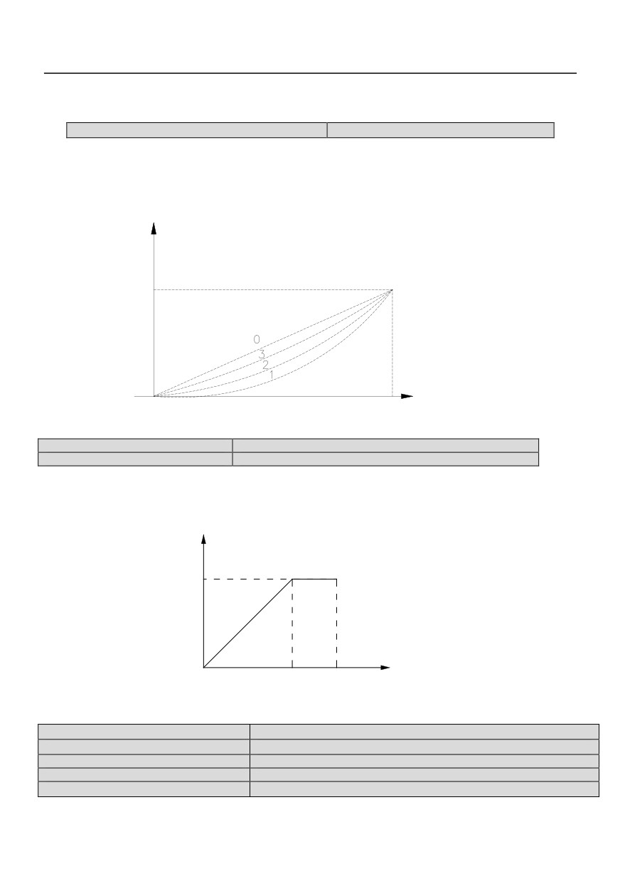
0: linear voltage/frequency mode (constant torque load), shown as curve 0 in Fig. 6-11;
1: Square voltage/frequency mode, shown as curve 1 in Fig. 6-11;
2: 1.5 times torque/frequency mode, shown as curve 2 in Fig. 6-11;
3: 1.2 times torque/frequency mode, shown as curve 3 in Fig. 6-11;
4: User defined V/F curve.
output voltage
Fmax
output frequency
Fig. 6-11 V/F curve
P4.01 Base voltage
Setting range: 0~440V
P4.02 Base frequency
Setting range: 10.00~ 600.0Hz
Basic V/F characteristic of HV390 series is shown in Fig. 6-12. BaseFrequency FBASE is the output
frequency corresponding to the rated output voltage UN. Its range is 10 to 600Hz. Generally, FBASE should
be selected according to rated frequency of the motor. In some special case, it can be selected according
to requirement. In this condition, both motor V/F characteristic and output torque should be considered.
output voltage
UN
output Frequency
0
FBASE FMAX
Fig. 6-12 Base voltage and frequency
P4.03Intermediate voltage 1
Setting range:0~P4.04
P4.04Intermediate voltage 2
Setting range:P4.03~100% (Reference voltage P4.01)
P4.05Intermediate frequency 1
Setting range:0~P4.06
P4.06Intermediate frequency 2
Setting range: P4.05~600.0Hz
P4.07 Torque boost
Setting range:0~10%(Reference voltage p4.01)
68
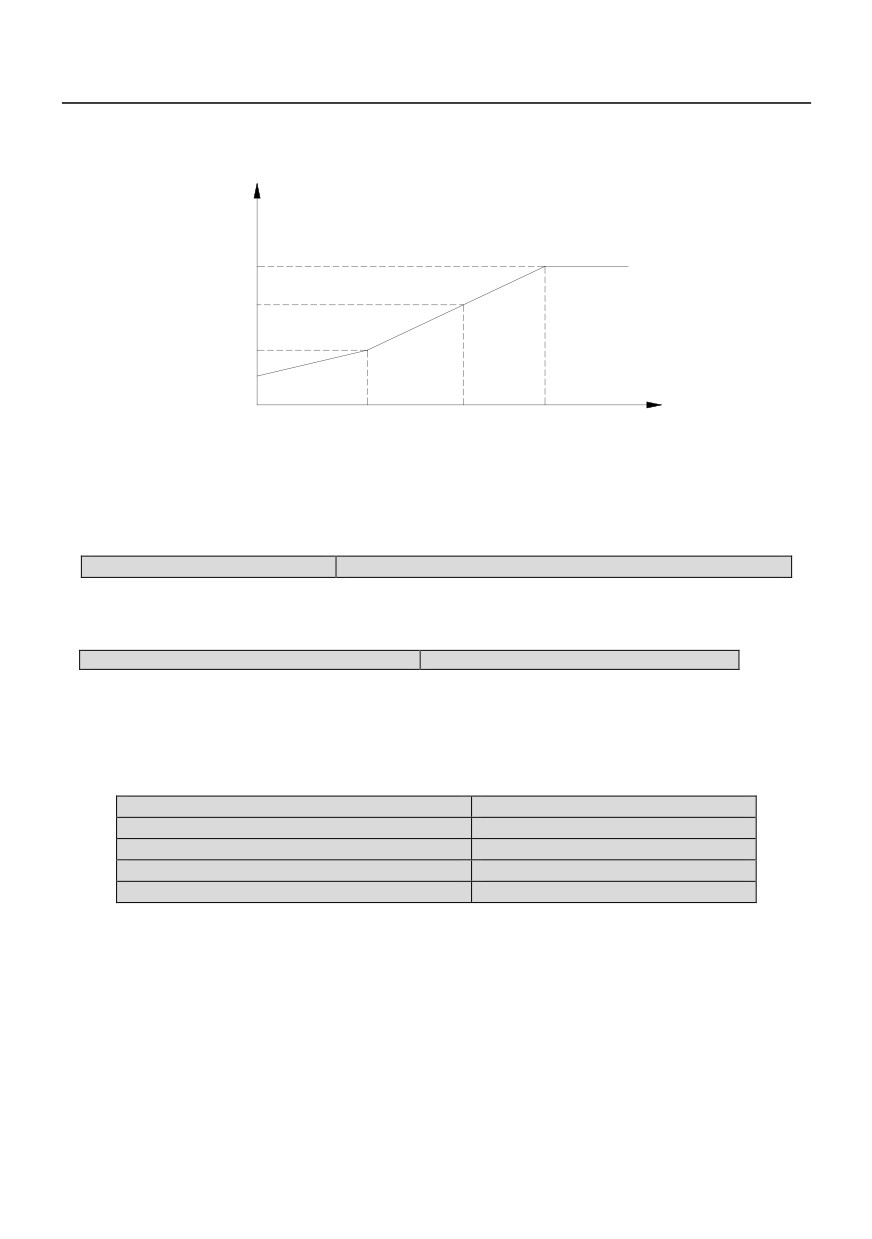
In order to compensate the torque drop at low frequency, the inverter can boost the output voltage in
the lowfrequency zone, which is shown in Fig. 6-13.
output
voltage
VN
P4.04
P4.03
Output
P4.07
frequency
0
P4.05
P4.06
FBASE
Fig. 6-13 Torque boost
Note:
Generally, factory setting (2%) can satisfy most applications. If over-current fault occurs during startup,
please increase this parameter from zero gradually until it meets requirement. Pay attention that large torque
boost could damage equipment.
P4.08 Slip compensation
Setting range:0.0~10%(Rated speed P3.04)
In V/F control mode, motor's speed will bedecreased with load rising. In order to ensurethe motor's
speed be close to synchronousspeed in rated load condition, slipcompensation can be done according to
thepreset frequency.
P4.09 AVR function
Setting range:0, 1
0: Disabled;
1: Enabled
AVR is auto voltage regulation. When theinverter's input voltage differs with the ratedinput voltage, the
inverter's output voltage canbe stablized by adjusting the width of PWMwave.
This function is disabled when the outputvoltage is higher than input voltage.
P5 Vector control funtion
P5.00 ASRproportional gain 1
Setting range:0.00~6.000
P5.01 ASR integration time 1
Setting range:0.00~9.999
P5.02 ASRproportional gain 2
Setting range:0.00~6.000
P5.03 ASR integration time 2
Setting range:0.00~9.999
P5.04 ASR switchingfrequency
Setting range:0.0~99.99Hz
Through P5.00~P5.04, user can set theproportional gain P and integration time I ofspeed regulator, so
as to change the speedresponse characteristic.
a.Speed regulator (ASR)'s structure is shown inFig.6-14, where KP is proportional gain P, and KI is
integration time I.
69
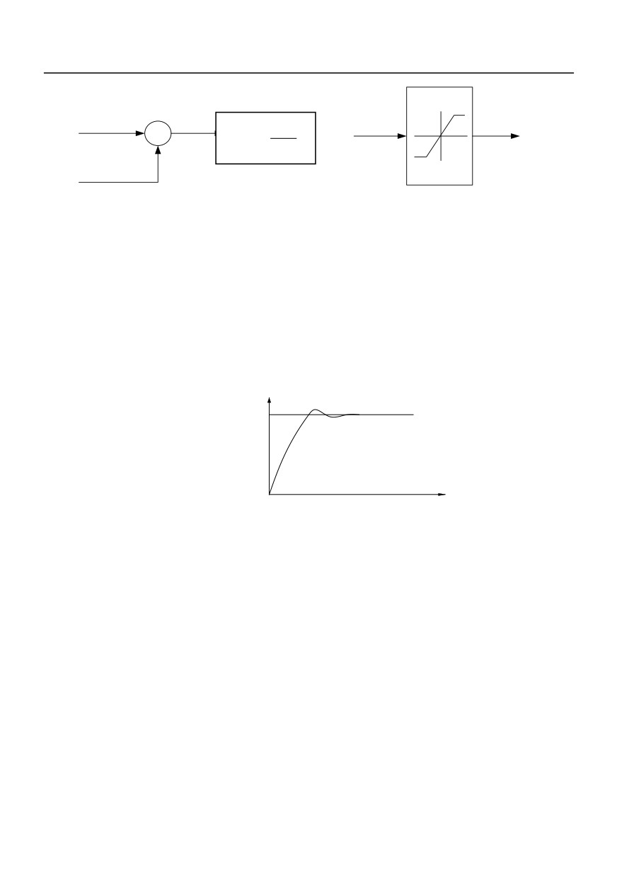
Frequency
Speed error
instruction
+
Given torque current
1
KP
(1+
)
-
KiS
Actual speed
Torque limit
(P5.07,P5.08)
Fig. 6-14 Simplified block diagram of ASR
If the integral time is set to 0 (P5.01=0, P5.03=0), which means integral function is disabled, and the
speed loop is simply a proportion regulator.
b.Adjustment of proportion gain P andintegration time I for speed regulator
Increasing P will fasten system transient response, but system oscillation may occur given too big
P.Decreasing I will fasten transient response, but system oscillation and overshoot may occur given too
small.
Normally, user may tune P first, increase its value as long as no system oscillation occurs; then adjust I,
ensuring fast response without overshoot. Figure 6-15 shows better speed step response if P, I are set
properly. Speed response can be monitored through analog terminals AO1 and AO2. Refer to P8 parameter
group for detail information.
Reference
speed
Fig. 6-15 Step response with better dynamic performance
70

Note:
With improper PI parameters, after accelerating to high speed, over-voltage during Dec process may
occur (Without external braking resistor or unit), which is caused by regenerative braking after speed
overshoot. To avoid this fault, user can tune PI parameters.
Adjustment of PI parameter in high/low speed applications
If system is required to respond quickly both in low and high frequency operation with load, user may
set ASR switching frequency (P5.04). Normally, when the system runs at low frequency, the transient
response performance can be improved by increasing P and decreasing I. Adjust ASR parameters following
the procedures below:
Set appropriate switching frequency P5.04;
Tune proportional gain P5.00 and integrationtime P5.01 for low-speed application, andensure no
oscillation and good response performance at low frequency.
Next, tune proportional gain P5.02 andintegration time P5.03 for high-speed application, and ensure
no oscillation and good response performance at high frequency.
P5.05 Slip compensation gain
Setting range:50.0~200.0%
P5.05 is used to calculate slip frequency. Setting value 100% means rated slip frequency corresponds
to rated torque current. User may decrease/increase the settings of P5.05 to adjust the speed control's
difference accurately.
Note:
This function is valid to open loop vector control mode. For close loop vector control mode, F5.05 can
be set to 100% for most applications.
P5.06 Torque control
Setting range:0, 1
This function is reserved.
P5.07 Driving torque lilmit
Setting range:0.0~200.0% (motor’s rated current)
P5.08 Braking torque limit
Setting range:0.0~200.0%(motor’s rated current)
Torque limiting is used to limit output torque current of speed regulator'.
71
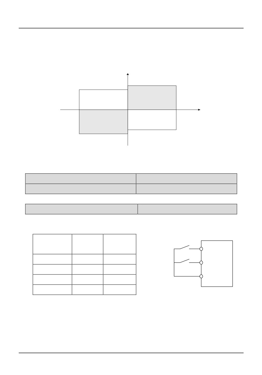
Torque limit is the percentage of the motor’s rated current; If the torque limit is 100%, then the torque
current limit is the motor's rated current. P5.07 and P5.08 limit the output torque in driving state and braking
state respectively, which is shown in Figure 6-16.
Output
positive
torque
P5.07
P5.08
Power state
Braking state
REV
Motor speed
Braking state
Power state
P5.08
P5.07
Negative
moment
Fig. 6-16 Torque limit function
P5.09Retain
P5.10 Retain
P6 I/O output terminal
P6.00 FWD/REV running
Setting range: 0~3
0:Two-line operation mode 1
Running
FWD
REV
K1
command
DI1(FWD)
K2
0
0
Stop
DI2(REV)
0
1
REV
COM
1
0
FWD
1
1
Stop
Fig. 6-17 Two-line control mode 1
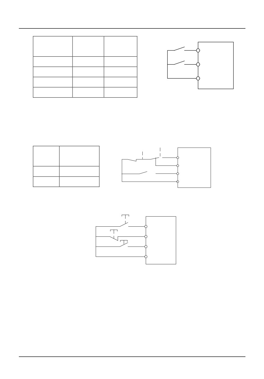
In Fig. 6-17, terminal DI1 is defined as running FWD, and DI2 is defined as running REV.
1:Two-line operation mode 2
72
Running
K1
FWD
REV
command
DI1(FWD)
K2
0
0
Stop
DI2(REV)
0
1
Stop
COM
1
0
FWD
1
1
REV
Fig.6-18 Two-line control mode 2
In Fig. 8-18, terminal DI1 is defined as running FWD, and DI2 is defined as running REV.
2: Three-wire operation mode 1
STO RUN
K
Running
P
DI1(FWD)
command
DIi
K
0
FWD
DI2(REV)
1
REV
COM
i=3,4,5,
Fig. 6-19 Three-wire operation mode 1
3: Three-wire operation mode
FWD
DI1(FWD)
STOP
DIi
REV
DI2(REV)
COM
i=3,4,5
Fig. 6-20 Three-wire operation mode 2
In Fig.6-19 and 6-20, DI1 is defined as running FWD, DI2 is defined as running REV, and K is used
for selecting running direction;
In Fig. 6-19 and 6-20, STOP is a normally closed button for stopping the motor. RUN, FWD and REV
are normally open buttons for running the motor, and they are active at pulse edge.
In Fig. 6-19 and 6-20, DIi (I=3~5) is defined as three-wire running control terminal of DI3~DI5
In 3-wire mode, when DI3~DI5 is not selected, the inverter will report ERR4 fault.
73
P6.01 Up/down rate
Setting range:0.10~99.99Hz/s
Up/down rate: To define the increase/decrease rate when using up/down terminal to change
reference frequency.
P6.02 Selecting the function ofcontrol terminal DI1
Setting range:0~30
P6.03 Selecting the function ofcontrol terminal DI2
Setting range:0~30
P6.04Selecting the function ofcontrol terminal DI3
Setting range:0~30
P6.05Selecting the function ofcontrol terminal DI4
Setting range:0~30
P6.06Selecting the function ofcontrol terminal DI5
Setting range:0~30
Control terminals DI1~DI5 are programmabledigital input terminals. DI1~DI5 can be definedby setting
the values of P6.02~P6.08 respectively.
Programmable digital input terminal can beselected as “ no function” repeatedly (that is, itcan be set as 0
at the same time). Function description is shown below:
Content
Function
Content
Funtion
0
DI1~DI5: No function (can be
16
Free run to stop
selected repeatedly)
1
Run FWD
17
Three-wire control
2
Run Rev
18
Voltage/current switching
3
External reset
19
Input terminal for recording program
operation
4
Jog FWD (JOGF)
20
Start traverse operation
5
Jog REV (JOGR)
21
DC braking command
6
Multi-frequency 1
22
Acc/Dec disabled command
7
Multi-frequency 2
23
Switch between panel control mode and
externalterminal control mode
8
Multi-frequency 3
24
Counter trig signal
9
Multi-frequency 4
25
Counter reset signal
10
Terminals for selecting Acc/Dec time
26
PID dormancy waking up
1
74
11
Terminals for selecting Acc/Dec time
27
Counter reset signal
2
12
Normally open terminal for inputting
28
PID dormancy waking up
externalfault
13
Normally close terminal for inputting
29
switch between PID positive mode and
externalfault
negative mode
14
Frequency increase command
30
Emergence stop
15
Frequency decrease command
Note:
1. When DI1~DI4 is selected 0, no function is defined,When DI5 is selected0, the pulse frequency is
input
2. 1~2: input terminals for external operation control
In terminal control mode (P0.01=1), the terminal is used to select FWD/REV operation.
3.
3: External RESET
If fault alarm occurs, user can reset the inverter by external terminal. This function is active at
rising edge of pulse signal. It has the same function as STOP/RESET key.
4.
4~5: Terminal for external FWD/REV Jog running control.
In terminal control mode (P0.01=1), this terminal is used to select Jog operation.
5.
6~9: Multi-frequency terminals
In multi-frequency operation mode, 4 digital input terminals should be defined as the control
terminals. Through the combination of ON/OFF state of the 4 terminals, up to 15 values can be
defined set as preset frequency. Refer to parameter P2.09~P2.23 for details.
6.
10~11: Acc/Dec time terminals
By combination of the ON/OFF state of Acc/Dec time terminals, user can select Acc/ Dec time
1~4, refer to parameter P0.16,P0.17 and P2.00~P2.05 for more details. If this function is not
defined, Acc/Dec time 1 will be the default setting except in simple PLC operation mode.
7.
12~13: Normally open terminal for externalfault
Fault signal of externalequipment can be input via the terminal, which isconvenient for the drive
to monitor the fault ofexternal equipment. Once the drive receives thefault signal, it will display
“Er11”. During normal stop process, this function is disabled. The fault signalhas two input
75
modes, i.e. normally open andnormallyclose.
8.
14~15: Frequency increase/decease command
The running frequency can be set throughexternal terminals, thus the running frequencycan be
set remotely. At this time,P0.03 can beset to 2 or 3. When the terminal is ON, thefrequency
setting value is increased ordecreased at the rate defined by P6.01; when the terminal is OFF,
frequencysetting value keeps constant. When these twoterminals are ON at the same time,
frequencysetting value also keeps constant. Please referto P0.03 parameters description.
9.
16: Free run to stop terminal (FRS)
When the function terminal is ON, inverter stops output immediately andenter stopping state,
the motor enters free run to stop state.
10 .17: Three-wire control
If F6.00=2 or 3, this terminal is defined as three-wire control terminal whenthree-wire control
mode is selected. If If F6.00=2 or 3, and none of DI1~DI5 is defined as three-wire control
terminal, the inverter will report parameter setting fault ERR4. In this case, user should define
“three-wire control terminal” first, and then define “three-wire control mode” (P6.00=2 or 3).
11. 18: Switching input signal
If analog setting mode is selected, (P0.09=4、5 or 6), this function is used to switch reference
channel.
P0.09=4:
If this terminal is OFF, reference signal is decided by settings of master given
If this terminal is ON, reference signal is decided by settings of panel potentiometer
P0.09=5:
If this terminal is OFF, reference signal is decided by settings of master given
If this terminal is ON, reference signal is decided by settings of panel potentiometer +auxiliary
given
P0.09=6:
If this terminal is OFF, reference signal is decided by settings of master given
If this terminal is ON, reference signal is decided by settings of panel potentiometer -auxiliary
given
12. 20: Start traverse operation
If the traverse operation is set to manual start,then traverse function is enabled if this function
76
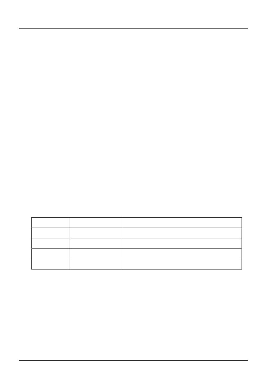
isselected. Refer to Pb parameter group for details.
13.22: DC braking command
When the inverter is in Dec-to-stop process,and the running frequency is lower than initialfrequency of
DC injection braking defined in P1.06, this function is enabled. When theterminal is ON, DC injection
braking isperformed under braking voltage defined in P1.08. DC injection braking is ended onlywhen the
terminal is OFF.
When this function is enabled, parameters of DC injection braking time are invalid.
14. 23: Acc/Dec disabled command
When the terminal is ON, the invertertemporarily inhibits executing the Acc/Deccommand and runs at
current frequency. Whenthe terminal is OFF, normal Acc/Deccommands can be executed. If there is
anycontrol signal with higher priority input such asexternal fault signal, the inverter will exitAcc/Dec inhibit
state immediately and executespecified processing procedures.
15. 24: Switch between panel control mode and externalterminal control mode
This function is used for selecting the physicschannel that inputs inverter’s running
controlcommand:Selecting between keypad andexternal terminal to input control commands.
Commands input via external terminals includeFWD, REV, JOGF, JOGR, RUN and STOP.
This function is used in conjunction with ON/OFF stateand the setting value of P0.01.
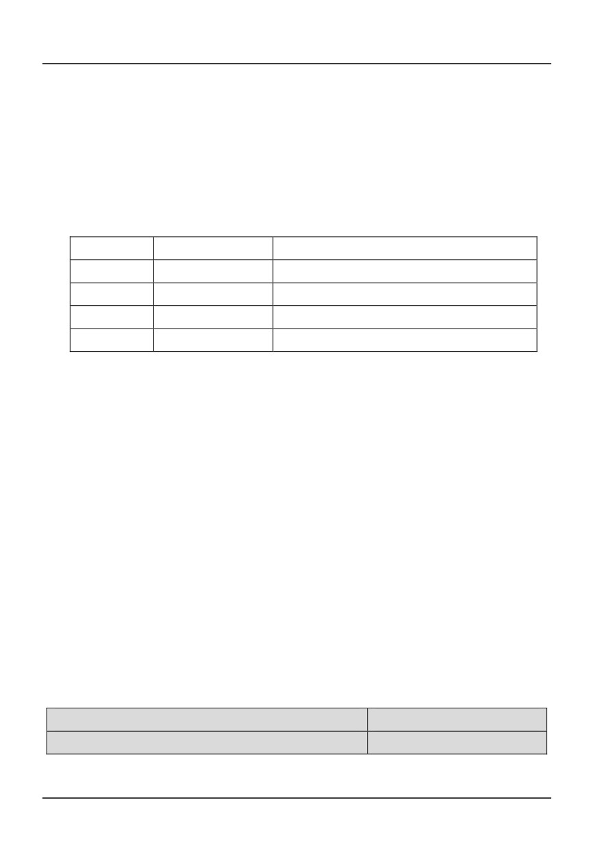
The control logic is shown in the Table below.
F0.01
Terminal state
Source of control command
0
ON
Externalterminals
0
OFF
Keypad
1
ON
Keypad
1
OFF
Externalterminals
This function is enabled during running state. User should pay attention to the drive’s running
status after switching.
If the drive is in keypad control mode first, connect the terminal (ON), there are 2 cases: if running
command from external terminal is valid, such as FWD terminal is ON in two-wire control mode, then
the drive’s operation state will not change; if running command from external terminal is invalid, the
drive will stop running.
77
16.
25: Switch between panel control mode and externalterminal control mode
This function is used for selecting the physicschannel that inputs inverter’s running
controlcommand:Selecting between keypad andexternal terminal to input control commands.
Commands input via external terminals includeFWD, REV, JOGF, JOGR, RUN and STOP.
This function is used in conjunction with ON/OFF stateand the setting value of P0.01.
The control logic is shown in the Table below.
P0.01
Terminal state
Source of control command
0
ON
Externalterminals
0
OFF
Keypad
1
ON
Keypad
1
OFF
Externalterminals
17.26: Counter trig signal
It is the input terminal of the drive’s internal counter. If the input signal of theterminal changes from ON to
OFF, thecounting value is increased by 1.
18.27: Counter reset signal
This terminal is used to clearthe inverter's internal counter, and is used inconjunction with Function 24
"Counter trigsignal".
When the terminal is ON, internal counter iscleared to 0.
19. 28: PID dormancy waking up
When PA.17=2 and this terminal is ON, PID control will exit dormancy state and execute normal PID
function.
20.29: switch between PID positive mode and negative mode:
When PA.00 is set to 0,PID positive mode is selected with the terminal is off ; negative modeis
selectedwiththe terminal is on.
21. 30:“Emergence stop”
If the terminal defined with the function is on, the inverter is in emergence stopstatus( motor free stop)
P6.09 Programmable relay 1
Setting range:0~20
P6.10 Output terminal Y1 definition
Setting range:0~20
Function selection of programmable relay output terminals and open collector output terminals is
78
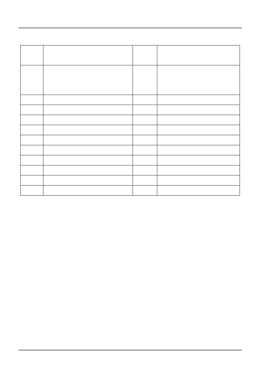
shown in the table below.
Conten
Function
Content
Function
t
0
Programmable relay 1: No operation
11
Over voltage stall
Output terminal Y1: No operation
1
Drive ready
12
External stoppingcommand
2
Drive running signal1
13
Preset counting value arriving
3
Drive running signal2
14
Specified counting value arriving
4
Frequency arriving signal
15
Low voltage lockup signal
5
Frequency detection threshold 1
16
Overload pre-alarm
6
Frequency detection threshold 2
17
Drive failure signal
7
High limit frequency arriving
18
Zero speed running
8
Low limit frequency arriving
19
Program running completed
9
Overload signal
20
PG cable broken
10
Over current stall
Functions in the table above are described as following:
0
0: No function is defined by programmable relay output terminal 1, and open collector output
terminal Y1. is defined as frequency signal output.
1
1: Drive ready
The drive is in normal waiting state, and terminals output indication signal.
2
2: Drive running signa l
The drive is in running state, and the terminal outputs indication signal.
3
3: Drive running signa2
In run status, when the drive’s output frequency is 0Hz, the terminal does not output indication
signal; when the drive’s output frequency is above 0Hz, the terminal does output indication signal
4
4: Frequency arriving signal
When the drive’s output frequency arrives preset frequency, the terminal outputs indication signal.
It is used in conjunction with parameter P6.11.
5
5~6: Frequency detection threshold 1 and 2
When the drive’s output frequency arrives specified value, the terminal outputs indication signal,
79