HV390 Series Frequency Inverter. User Manual (Version: 3.1.14) - page 1
Contents
CHAPTER 1 INTRODUCTION TO HV390 SERIES INVERTER ··················· 6
1.1 PRODUCT MODEL DESCRIPTION ······················································· 6
1.2 SAFETY PRECAUTIONS ·································································· 7
1.3 PRODUCT SERIES ········································································ 8
1.4 PRODUCT STANDARD SPECIFICATION ················································· 12
1.5 USE NOTE················································································· 13
CHAPTER 2 INVERTER INSTALLATION ·············································· 15
2.1 INSTALLATION ENVIRONMENT ·························································· 15
2.2 MECHANICAL INSTALLATION ···························································· 16
2.3 INVERTER SHAPE AND INSTALLATION DIMENSIONS ·································· 17
2.4 THE SHAPE AND MOUNTING DIMENSIONS OF THE OPERATING PANEL(UNIT:MM)
·································································································· 18
2.5 KEYBOARD TRAY ········································································· 18
CHAPTER 3 WIRING OF INVERTER···················································· 19
3.1 CONNECTION OF THE PRODUCT AND PERIPHERAL DEVICES······················ 19
3.2 DESCRIPTION OF PERIPHERAL DEVICES FOR MAIN CIRCUIT ····················· 20
3.3 LECTOTYPE OF MAIN CIRCUIT PERIPHERAL DEVICES ····························· 20
3.4 TERMINAL WIRING ······································································· 22
3.5 CONTROL CIRCUIT TERMINAL FUNCTION·············································· 23
3.6 PERIPHERAL DEVICE SELECTION OF CONTROL CIRCUIT ···························· 24
3.7 FUNCTION OF MAIN CIRCUIT TERMINAL ··············································· 24
3.8 ATTENTION FOR MAIN CIRCUIT WIRING ·············································· 25
CHAPTER 4 KEYBOARD OPERATION ················································ 28
4.1 KEYBOARD INTRODUCE ································································· 28
4.2 DESCRIPTIONS OF INDICATORS ························································ 28
4.3 BUTTON DESCRIPTION OF KEYBOARD ················································ 29
3
4.4 KEYPAD OPERATING STATUS ··························································
29
4.5 PANEL OPERATION METHOD ···························································
30
4.6 PARAMETER DISPLAY ···································································
32
4.7 MOTOR AUTO-TUNING PROCEDURE ···················································
33
CHAPTER 5 LIST OF PARAMETERS···················································
35
5.1 FUNCTION PARAMETER TABLE·························································
35
CHAPTER 6 DETAIL FUNCTION INTRODUCTION ·································
55
P0 BASIC FUNCTION PARAMETERS ························································
55
P1 AUXILIARY FUNCTION PARAMETERS 1 ·················································
60
P2 AUXILIARY FUNCTION PARAMETERS 2 ·················································
63
P3 MOTOR PARAMETERS····································································
67
P4 DEDICATD FUNCTION FOR V/F CONTROL ·············································
68
P5 VECTOR CONTROL FUNTION ····························································
69
P6 I/O OUTPUT TERMINAL ···································································
72
P7 ANALOG INPUT TERMINAL FUNCTION ··················································
84
P8 ANALOG OUTPUT TERMINAL·····························································
85
P9 PROGRAM OPERATING PARAMETERS··················································
87
PA PID PARAMETER··········································································
89
PB TRAVERSE FUNCTION ····································································
92
PC COMMUNICATION AND BUS CONTROL FUNCTION ····································
93
PD FAULTS AND PROTECTION PARAMETERS ··············································
94
PE FACTORY RESERVED ····································································
98
PF FACTORY RESERVED ····································································
99
PH DISPLAY FUNCTION ······································································
99
CHAPTER 7 FAULT DIAGNOSIS AND TROUBLESHOOTING ················ 102
7.1 FAULT QUERY AT FAULT ······························································· 102
7.2 LIST OF FAULT AND ALARM INFORMATION ·········································· 102
7.3 TROUBLESHOOTING PROCEDURES ················································· 107
4
CHAPTER 8 ROUTINE REPAIR AND MAINTENANCE ·························· 108
8.1 ROUTINE MAINTENANCE······························································ 108
8.2 PERIODIC MAINTENANCE ····························································· 109
8.3 COMPONENT REPLACEMENT ························································ 109
8.4 INSULATION TEST ······································································ 109
APPENDIX A COMMUNICATION PROTOCOL ··································· 111
APPENDIX B CONTROL MODE SETTING PROCESS··························· 125
PRODUCT FEEDBACK ··································································· 126
WARRANTY AGREEMENT ······························································ 127
5
Chapter 1 Introduction to HV390 Series Inverter
1.1 Product Model Description
Before unpacking the product, please check product packaging for shipping damage caused by
careless transportation and whether the specifications and type of the product complies with the order.
If any questions, please contact the supplier of HV390 series inverter, or directly contact the company.
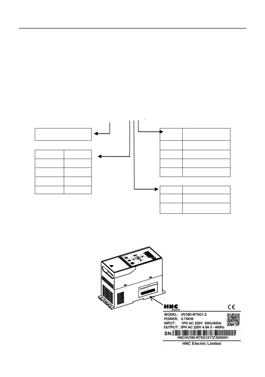
Model specification:
HV390-1R5 G3
Inverter Series
Code
Inverter Type
1-2
single phase 220V
Code
Motor
2
three-phase 220V
R75
0.75KW
3
three-phase 380V
1R5
1.5KW
4
three-phase 460V
2R2
2.2KW
5R5
5.5KW
Code
Inverter Type
G
General purpose
P
Fan/Pump
Fig. 1-1 Inverter symbol description
Below the right plate of the inverter case, a nameplate indicating the type and the rated value of the
converter is attached,The contents are as follows:
6
1.2 Safety Precautions
Description of safety marks:
Danger: The misuse may cause fire, severe injury, even death.
Note: The misuse may cause medium or minor injury and equipment damage.
Procedure qualification
This product must be operated by trained professionals. Moreover, operations personnel must undergo
professional training, familiar with equipment installation, wiring, operation and maintenance, and the correct
response to the use of various emergency situations arise.
Safety guidance
A warning sign is put forward for your safety, is to prevent the operation of injuries, and take the product and
related system damage measures; please read this manual carefully before use, and in strict accordance
with the safety rules in this manual and warning signs for the operation.
●Proper transport, storage, installation, and careful operation and maintenance is very important for the safe
operation of the converter. During the transportation and storage to ensure the inverter from shock and
vibration, but also must ensure that the store in a dry, non corrosive gas, no conductive dust and
environmental temperature less than 60 degrees Celsius.
●This product with the dangerous voltage, and it is under the control of the movement mechanism with
potential risk, if you do not comply with the provisions of this manual or not according to the operation
requirements, may cause casualties, damage to the products and related systems.
●Do not make the connection work in power on state, otherwise the risk of death caused by electric shock; in
wiring, inspection, maintenance and operation, disconnect all power related equipment, and confirm the
main circuit of the DC voltage has dropped to a safe level, wait 5 minutes and then carry on the related work.
●The power line, the motor line and the control line must be fastened and connected. The grounding
terminal must be reliably grounded and the grounding resistance is less than 10 Omega
●The static electricity of the human body will seriously damage the internal sensitive devices, and please
comply with the measures and methods stipulated in the electrostatic prevention measures (ESD) before the
relevant operations, otherwise the frequency converter may be damaged
●Since the output voltage of the inverter is a pulse waveform, if the output side is equipped with capacitors to
improve the power factor or lightning protection varistors, etc., be sure to remove or modify the input side of
the inverter
7
●The output side of the inverter shall not switch devices such as circuit breakers and contactors (if the
switching device must be switched on the output side, the output current of the inverter must be zero when
the switch is switched on control)
●No matter where the fault occurs in the control equipment, it is possible to cause a shutdown and major
accidents. Therefore, please take the necessary external protection measures or backup devices●This
product can only be used in accordance with the use of the manufacturer. Without permission, it shall not be
used in special areas such as emergency response, rescue, ship, medical, aviation, nuclear facilities, etc.
●Only the maintenance of products by the company or the company's licensing professionals, unauthorized
modification, the use of non recognition of the company's accessories, may lead to product failure. In the
maintenance, any defective devices must be promptly replaced.
1.3 Product Series
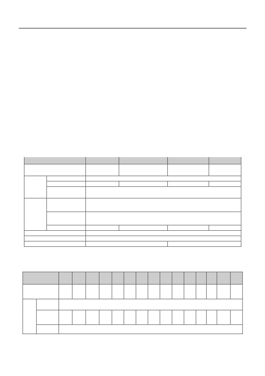
HV390−□□□G1-2 Single phase AC 220V constant torque / heavy load application
Power(kW)
0.4
0.75
1.5
2.2
Motor
0.4
0.75
1.5
2.2
power(kW)
Voltage(V)
Three-phase 0 to rated input voltage
Rated curren(A)
2.5
4.0
7.0
10
Output
Overload
150%
1 minute,180%
2 seconds, 200%
0.5 seconds, 10 minutes (inverse
capacity
time lag feature)
Rated voltage
/
Single phase 200V~240V;50Hz/60Hz
frequency
Input
Allowable voltage
180V~260V;Voltage imbalance:≤3% ;Allowable frequency fluctuation:±5%
range
Rated curren(A)
5.9
8.3
14.1
24.2
Brake unit
Built-in as standard
Protection class
IP20
Cooling mode
Self-cooling
Forced air convection cooling
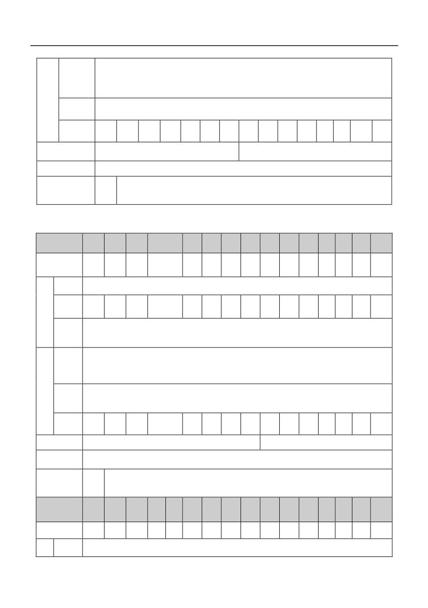
HV390−□□□G2 Three phase AC 220V constant torque / heavy load application
Power(kW)
0.4
0.75
1.5
2.2
4.0
5.5
7.5
11
15
18.5
22
30
37
45
55
Motor
0.4
0.75
1.5
2.2
4.0
5.5
7.5
11
15
18.5
22
30
37
45
55
power(kW)
Voltage
Three-phase 0 to rated input voltage
(V)
Out
Rated
current
2.5
4
7
10
16
25
32
45
60
75
90
110
152
176
210
put
(A)
Overload
150%
1 minute,180%
2 seconds, 200%
0.5 seconds,10 minutes (inverse time lag feature)
capacity
8
Rated
voltage /
3 phase 220V±15%;50Hz/60Hz
frequency
Input
Allowable
voltage
220V±15%;Voltage imbalance:≤3% ;Allowable frequency fluctuation:±5%
range
Rated
122
157
215.
current
4.1
5.3
8.0
11.8
18.1
28.0
37.1
49.8
65.4
81.6
97.7
185.3
.1
.4
8
(A)
Brake unit
Built-in as standard
External braking unit needed
IP20
Protection class
Self-
Cooling mode
cooli
Forced air convection cooling
ng
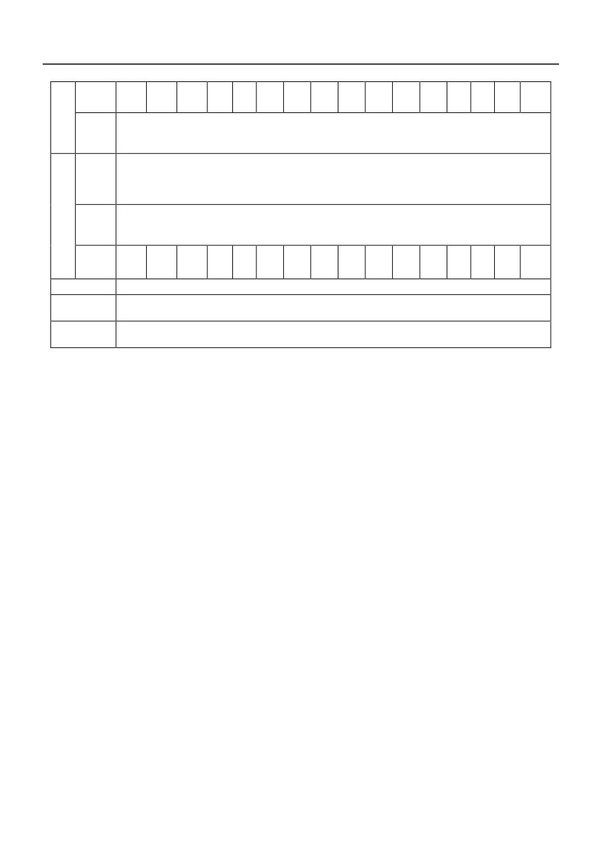
HV390−□□□G3 Three phase AC 380V constant torque / heavy load application
Power(kW)
0.75
1.5
2.2
4.0
5.5
7.5
11
15
18.5
22
30
37
45
55
75
Motor
0.75
1.5
2.2
4.0
5.5
7.5
11
15
18.5
22
30
37
45
55
75
power(kW)
Voltage
Three-phase 0 to rated input voltage
(V)
Rated
Out
current
2.5
3.7
5.1
8.5
13
16
25
32
38
45
60
75
90
110
150
(A)
put
Overlo
ad
150%
1 minute,180%
2 seconds, 200%
0.5 seconds,10 minutes (inverse time lag feature)
capacit
y
Rated
voltage
/
3 phase 380V±15%;50Hz/60Hz
frequen
cy
Inp
Allowa
ut
ble
380V±15%;Voltage imbalance:≤3% ;Allowable frequency fluctuation:±5%
voltage
range
Rated
80.
96.
117.
current
4.3
5.2
6.0
10.5
15.5
20.5
27.5
37.1
41.9
49.3
65.7
166.4
6
4
6
(A)
Brake unit
Built-in as standard
External braking unit needed
Protection
IP20
class
Self-
Cooling
cooli
Forced air convection cooling
mode
ng
Power(kW)
90
110
132
160
185
200
220
250
280
315
355
400
450
500
560
630
Motor
90
110
132
160
185
200
220
250
280
315
355
400
450
500
560
630
power(kW)
Voltage
Out
Three-phase 0 to rated input voltage
(V)
9
put
Rated
current
170
210
250
300
340
380
415
470
520
600
650
725
820
860
950
1100
(A)
Overlo
ad
150%
1 minute,180%
2 seconds, 200%
0.5 seconds,10 minutes (inverse time lag feature)
capacit
y
Rated
voltage
/
3 phase 380V±15%;50Hz/60Hz
frequen
cy
Inp
Allowa
ble
ut
380V±15%;Voltage imbalance:≤3% ;Allowable frequency fluctuation:±5%
voltage
range
Rated
184.
226.
268.
321
406.
442.
555.
650.
754.
797.
current
368
503
846
885
990
1150
3
8
1
.1
6
7
9
7
5
6
(A)
Brake unit
External braking unit needed
Protection
IP20
class
Cooling
Forced air convection cooling
mode
*Note:HV390−185G3 and above products are equipped with external DC reactor as standard.
10
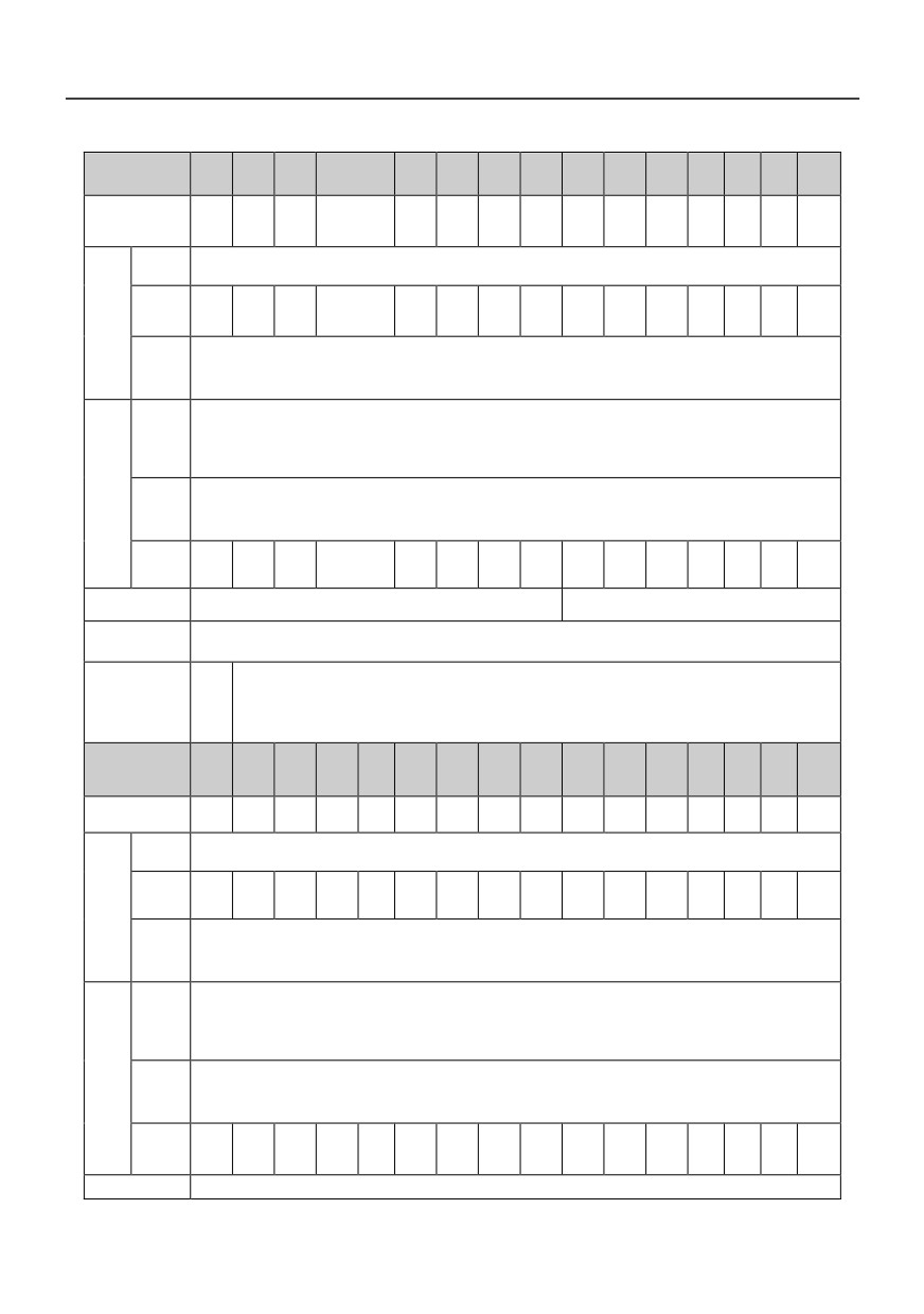
HV390−□□□G4 Three phase AC 480V constant torque / heavy load application
Power(kW)
0.75
1.5
2.2
4.0
5.5
7.5
11
15
18.5
22
30
37
45
55
75
Motor
0.75
1.5
2.2
4.0
5.5
7.5
11
15
18.5
22
30
37
45
55
75
power(kW)
Voltag
Three-phase 0 to rated input voltage
e(V)
Rated
Out
current
2.5
3.7
5.0
8
11
15
22
27
34
40
55
65
80
100
130
(A)
put
Overlo
ad
150%
1 minute,180%
2 seconds, 200%
0.5 seconds,10 minutes (inverse time lag feature)
capacit
y
Rated
voltage
/
3 phase 460V±15%;50Hz/60Hz
freque
ncy
Allowa
Input
ble
460V±15%;Voltage imbalance:≤3% ;Allowable frequency fluctuation:±5%
voltage
range
Rated
66.
81.
101.
current
4.1
4.9
5.7
9.4
12.5
18.3
23.1
29.8
35.7
41.7
57.4
137.4
5
7
9
(A)
Built-in as standard
Brake unit
External braking unit needed
Protection
IP20
class
Self
-coo
Cooling mode
Forced air convection cooling
ling
Power(kW)
90
110
132
160
185
200
220
250
280
315
355
400
450
500
560
630
Motor
90
110
132
160
185
200
220
250
280
315
355
400
450
500
560
630
power(kW)
Voltag
Three-phase 0 to rated input voltage
e(V)
Rated
100
Out
current
147
180
216
259
300
328
358
400
449
516
570
650
700
800
900
0
(A)
put
Overlo
ad
150%
1 minute,180%
2 seconds, 200%
0.5 seconds,10 minutes (inverse time lag feature)
capacit
y
Rated
voltage
/
3 phase 460V±15%;50Hz/60Hz
freque
ncy
Allowa
Input
ble
460V±15%;Voltage imbalance:≤3% ;Allowable frequency fluctuation:±5%
voltage
range
Rated
151.
220.
264.
309
334.
363.
407.
457.
533.
623.
706.
current
216
760
865
970
1100
8
7
2
.4
4
9
9
4
2
3
9
(A)
Brake unit
External braking unit needed
11
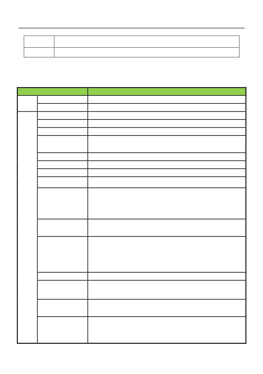
Protection
IP20
class
Cooling mode
Forced air convection cooling
*Note:HV390−185G4 and above products are equipped with external DC reactor as standard.
1.4 Product standard specification
Item
Specifications
Voltage frequency
single-phase 220V50/60Hz, three-phase 380V 50/60Hz
power
Allowable fluctuation
voltage:±15%,frequency:±5%
Frequency range
0-600Hz
Output frequency
The maximum frequency value ±0.1%
Output frequency
Operate keyboard up and down keys:0.01Hz Potentiometer analog input:0.2Hz
Run command given
The keyboard is given; the external terminal is given; the serial port is given by the
mode
host computer
carrier frequency
2.0-12.0KHz
Torque boost
0~20.0% adjustable, optional v/f curve optional
overload capacity
150% rated output current
1 minute,180% rated output current
2 second
Acc/Dectime
0.1~3600 second
Rated output voltage
Using the power supply voltage compensation function, the motor rated voltage is
100%, which can be set in the range of 50-100% (the output can not exceed the
input voltage)
Control
AVRadjustment function
When the network voltage fluctuates, the output voltage fluctuation is very small and
perfor
almost constant V/F
mance
PID control, acceleration and deceleration time is adjustable, variable deceleration
mode, carrier frequency, torque, current limiting, power off, restart, jump frequency
standard feature
control, lower frequency running, multi speed, swing frequency, RS485, analog
output, fault slip compensation, automatic reset
braking
Energy consumption braking, DC braking
Keyboard digital setting, external terminal AI1 (0-10V/0-20mA switchable), AI2
Frequency setting input
(0-10V/0-20mA switchable), RS485 and signal combination and terminal selection
Signal feedback input
External terminal AI1 (0-10V/0-20mA switchable), AI2 (0-10V/0-20mA switchable),
RS485
Input instruction signal
Start, stop, reverse, inching, multi segment speed, free parking, reset, acceleration
and deceleration time selection, frequency setting, channel selection, external fault
alarm, etc.
12
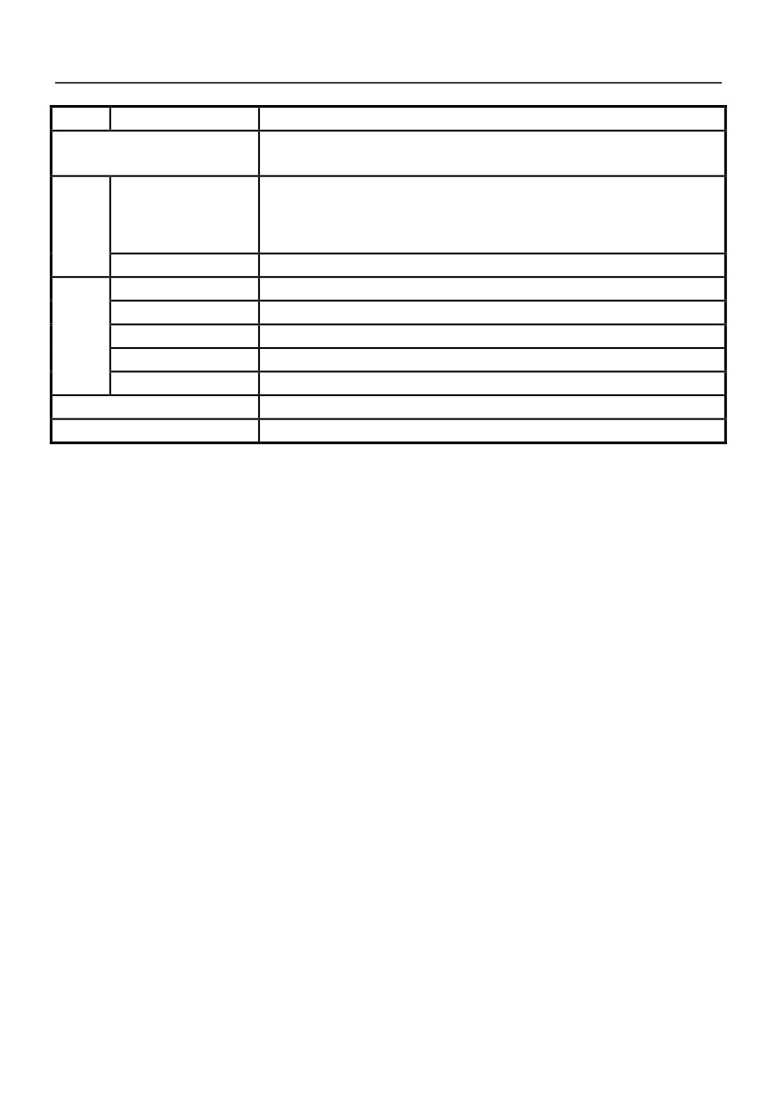
External output signal
Relay output, collector output, 0-10V output, 4-20mA output
Overvoltage, undervoltage, overcurrent, current limit, overload, overheating,
protective function
electronic thermal overload relay, overvoltage stall, data protection, etc.
Four digit display (LED)
15 kinds of parameters, such as frequency setting, output frequency, output voltage,
output current, motor speed, output torque, digital value terminals, program menu
display
parameters and 33kinds of Fault codes
indicator lamp (LED)
Run/stop status, etc.
Operat
Environment
Inside, low than 1000m, free from dust, corrosive gas and direct sunlight
Ambient temperature
-10℃~+40℃(bare machine -10℃~+50℃
,20%~90%RH(no condensing)
ing
Vibration
less than 0.5g
enviro
Storage temperature
-25℃~+65℃
nment
Installation
Wall mounted or surface mounted inside a cabinet
Protection class
IP20
Cooling
Forced air cooling.
1.5 Use note
The design of the inverter allows it to operate in an industrial environment with electromagnetic interference.
Usually, if the quality is good, it can ensure the safety of inverter and trouble free operation, please install to
ensure the inverter can run reliably and effectively avoid the electromagnetic interference caused by the
following rules.
●Ensure that the grounding cable of all control devices are connected to the inverter as transducer with
short and thick, reliably connected to public places or public star connection grounding bus motor; please
contact the nearest ground, please do not put the shell of the motor is connected to the earthing terminal or
inverter control system protection.
●When the equipment is not grounded, the contact leakage occurs. Please connect the grounding end
of the inverter to the equipment shell and motor shell, and the single phase 220V converter N terminal must
be connected to zero line
●Conductors are preferably flat and multicore because they are less impedance at high frequencies
●The ends of the truncated cables should be as neat as possible to ensure that the segments are as
short as possible
●Control cable wiring should be far away from the power supply cables and the motor cable, use wire
slot alone, and must be in power cables and the motor cable when crossing each other should adopt 90
degrees vertical cross.
13
●The cabinet is installed to ensure the contactor with a surge suppressor. Or, there is a 'R-C' damping
circuit is connected to the coil of AC contactor, the use of varistor and corresponding coil voltage; the coil DC
contactor is connected with a "freewheeling diode" or coil device voltage corresponding to the type of
varistor; the output control relay in inverter contactor contactor occasions and frequent action, this is
especially important.
●The connection wire of the motor shall be shielded cable or armored cable, and the grounding end of
the shielding layer can be reliably grounded by the cable grounding card
●Install "input noise filter" can reduce the electromagnetic interference brought from the grid side of
other equipment, the input side noise filter "must be as close as possible to the inverter power input terminal,
at the same time, with the same inverter filter must be reliable grounding.
●Install "the output side filter can reduce noise" wireless interference from the motor and the inductive
interference, "the output side filter noise" must be as close as possible to the inverter output terminals, at the
same time, with the same inverter filter must be reliable grounding.
●Shielded cable or twisted pair shall be used whenever the control loop is connected
●Adding the "zero phase reactor" in the power line near the inverter input terminal, adding the "zero
phase reactor" in the motor line near the inverter output terminals, adding "zero phase reactor" in the control
line near the inverter control terminal, can effectively reduce the electromagnetic interference and the main
power cable connected inverter induction.
●Grounding, correct and reliable grounding are the basic conditions for the safe and reliable operation
of this product. In order to properly connect the converter to the ground, please read the following cautions
carefully
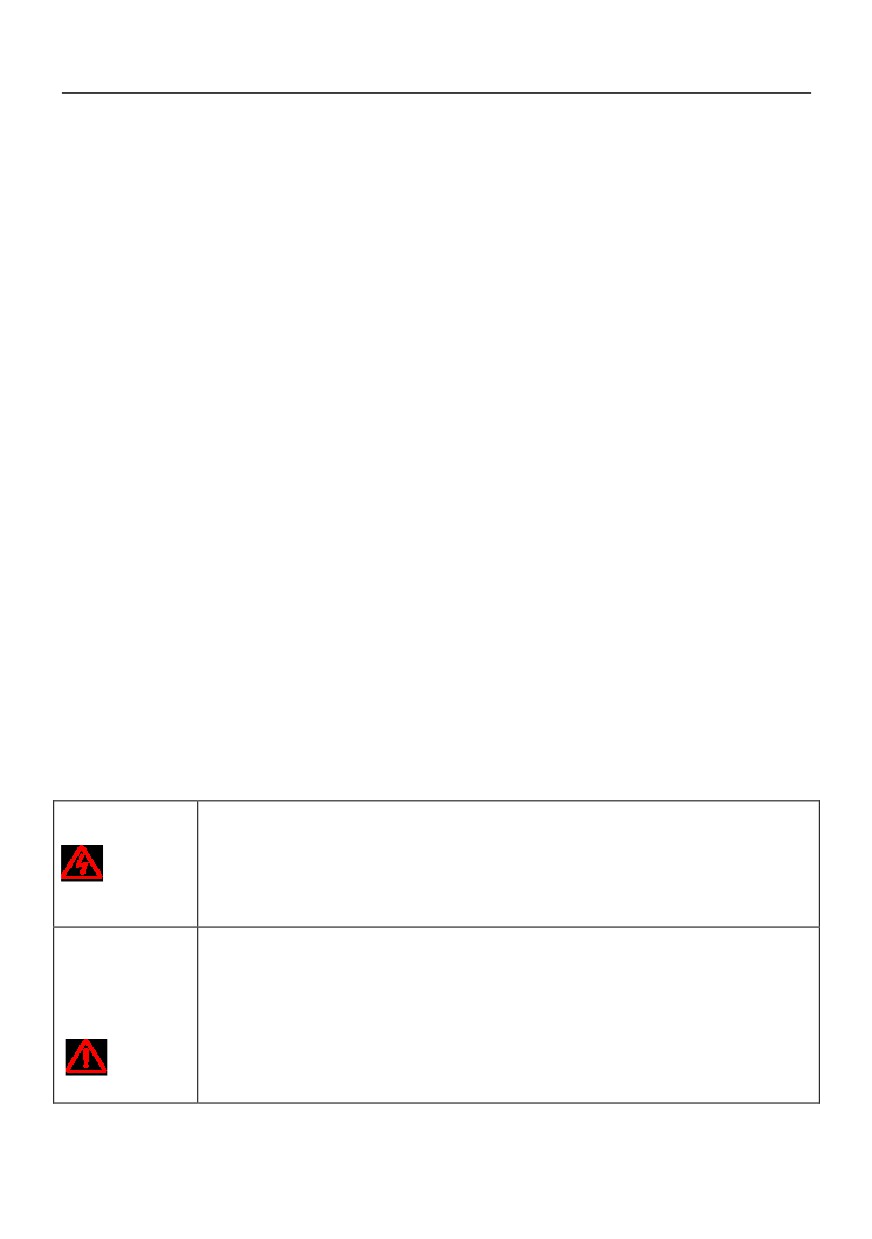
●To avoid electric shock, please use the dimensions specified in the electrical
equipment technical standard, and shorten the wiring length as much as possible, and
warning
the grounding resistance is below 10 Omega.Otherwise, the leakage current caused by
the inverter will lead to the unstable potential of the grounding terminal far from the
grounding point, which will lead to an electric shock accident
●Do not share the ground wire with the welder or power equipment that requires high
current / pulse current, otherwise it will cause abnormal operation of the inverter
●When using multiple inverters, do not loop the ground. Otherwise, the inverter will act
abnormally
●The motor must be grounded independently, and the motor casing can not be
Causion
connected to the ground terminal of the converter, nor can the same ground network be
shared with the control system
14

Chapter 2 Inverter Installation
To ensure the safe use of this product, to maximize the performance of the inverter and to ensure the
reliable operation of the inverter, please strictly follow the environment, wiring, ventilation and other
requirements described in this chapter
2.1 Installation environment
In order to give full play to the performance of this product and maintain its function for a long time, the
installation environment is very important. Please install this product in the environment that meets the
requirements shown in the following table
Environment
Requirement
Installation
Installation indoor without direct sunlight
environment
Work temperature
-10 ~ +40℃
Storage
-20 ~ +60℃
Temperature
Environment
No condensation under 95%RH
temperature
Please install the inverter in the following places:
●No oil fog, corrosive gas, flammable gas, dust and other places;
●Metal powder, oil, water and other foreign matter will not enter the frequency
converter inside the place (do not install the frequency converter on wood and other
Ambient
flammable substances above);
environment
●A place where radioactive substances are not flammable;
●A place where no noxious gas or liquid is found;
●A place where little salt is eaten;
●A place where there is no direct sunlight
Height above sea
Below 1000m
level
Vibration
Below 10~ 20Hz: 9.8m/s2
15
Below 20~55Hz∶5.9m/s2
●The inverter shall not be installed horizontally or horizontally, and vertical and
vertical installation must be guaranteed;
Installation and
●High resistance heating equipment such as braking resistance, please install
cooling
independently, avoid and inverter installed in the same cabinet, it is strictly prohibited
to brake resistance and other high heating equipment installed in the inverter inlet
2.2 Mechanical installation
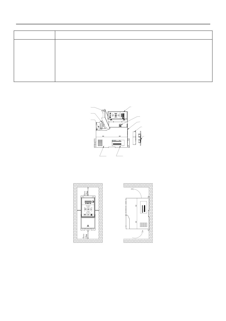
●HV390 series inverter components
Back cover
Keyboard
Control terminal
Keyboard interface
Main circuit terminal
Mullion
Fan
Fan cowl
Base
Rating plate
●Installation space, direction and space
Installation: single frequency governor to install in indoor ventilated place, and a wall hanging cabinet type or
vertical installation. And with the adjacent items or baffle (wall) must keep enough space.
Ventilation direction
Above
Above
50mm
50mm
Ventilation direction
installation diagram of single inverter
Multiple installation: when installing multiple inverters in the control cabinet, please ensure the following
installation space
16
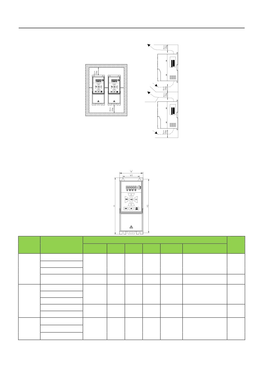
Above
Above
Above
50mm
50mm
50mm
Ventilation direction
Installation diagram of multi inverters
2.3 Inverter shape and installation dimensions
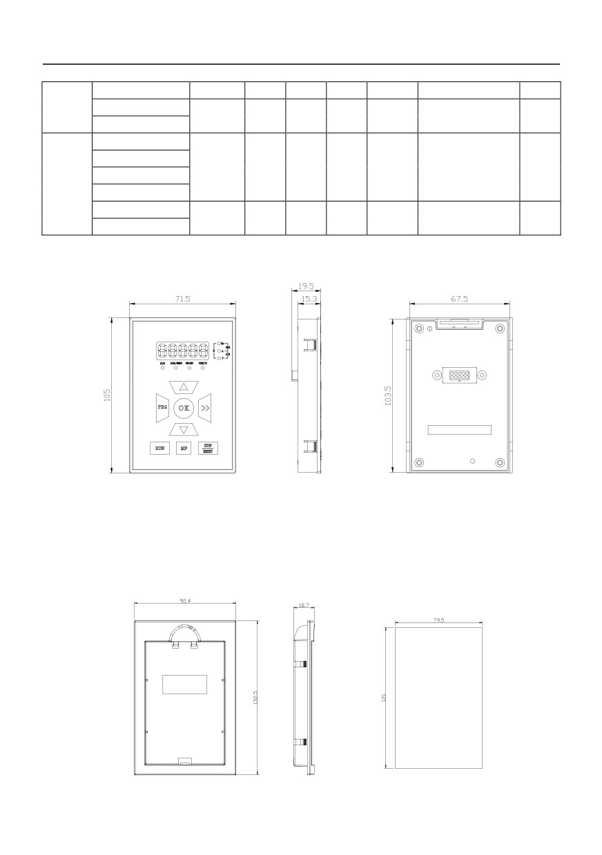
Outline construction and installation dimension(mm)
Weig
Voltage
Inverter model
ht
level
W
H
D
W1
H1
Mounting hole d
(kg)
HV390−R40G1-2
single
HV390−R75G1-2
78
188
126
55
178
4
1.5
phase
HV390−1R5G1-2
220V
HV390−2R2G1-2
96
225
137
65
215
4
2
HV390−R40G2
Three
HV390−R75G2
78
188
126
55
178
4
1.5
-phase
HV390−1R5G2
220V
HV390−2R2G2
96
225
137
65
215
4
2
HV390−004G2
HV390−R40G3
Three
-phase
HV390−R75G3
78
188
126
55
178
4
1.5
380V
HV390−1R5G3
17
HV390−2R2G3
HV390−004G3
96
225
137
65
215
4
2
HV390−5R5G3
HV390−R40G4
HV390−R75G4
78
188
126
55
178
4
1.5
Three
HV390−1R5G4
-phase
HV390−2R2G4
460V
HV390−004G4
96
225
137
65
215
4
2
HV390−5R5G4
2.4 The shape and mounting dimensions of the operating panel(unit:mm)
Keyboard (HV390-DP01)
Rear view of Keyboard
2.5 Keyboard tray
HV390−DP03 is the operation panel to install plate cabinet use, its shape and size are as follows:
18
Chapter 3 Wiring of Inverter
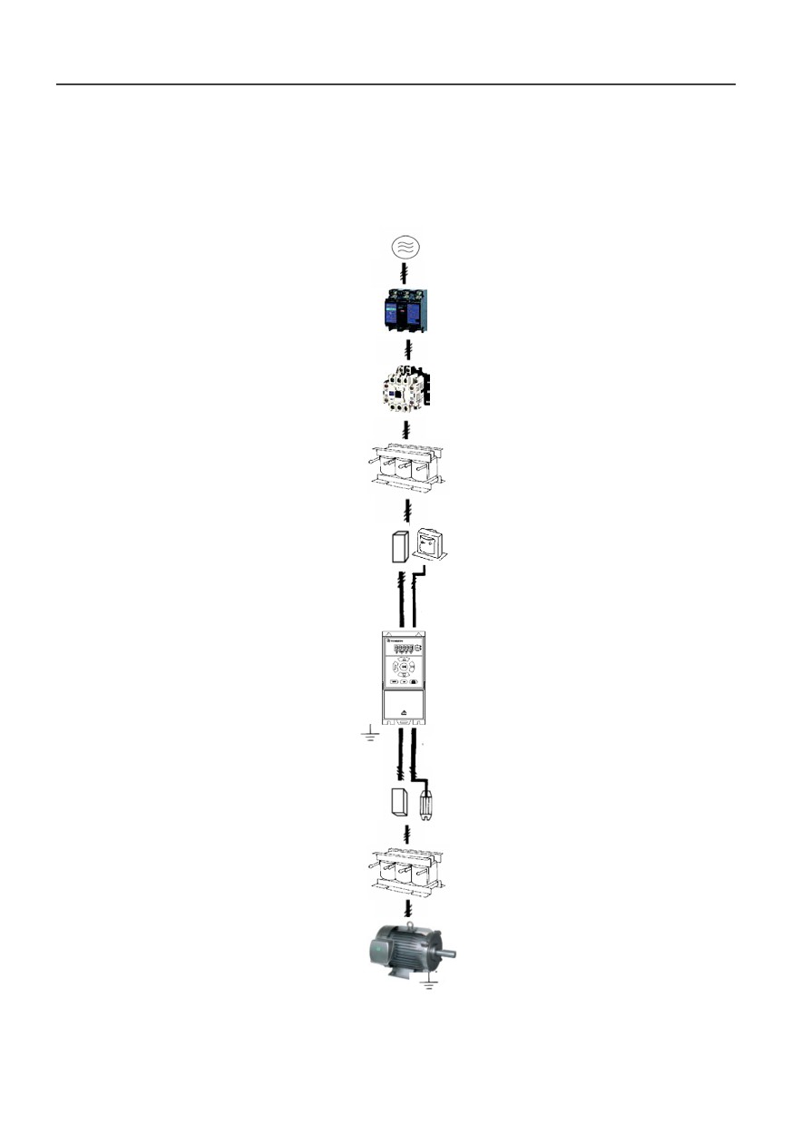
3.1 Connection of the Product and Peripheral Devices
Power supply
Circuit breaker or
leakage circuit breaker
Contactor
Input AC reactor
Input noise filter
DC reactor
Inverter
Grounding
Output noise filter
Braking resistor
Output AC reactor
Motor
Grounding
Fig.3−1 Connection diagram of the product and peripheral devices
19
3.2 Description of Peripheral Devices for Main Circuit
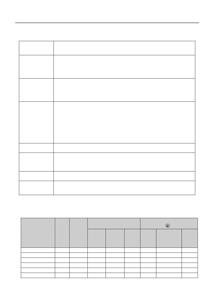
The capacity of the circuit breaker shall be 1.5 ~ 2 time of the rated current of the inverter.
Circuit breaker
The time features of the circuit breaker shall fully consider the time features of the inverter
overload protection.
Because the inverter output is the high-frequency pulse, there will be high-frequency leakage
current. Special leakage circuit breaker shall be used when installing leakage circuit breaker
Leakage circuit
at the input end of the inverter.
breaker
It is suggested that B type leakage circuit breaker be used, and the leakage current value
shall be set as 300mA.
Frequent open and close of contactor will cause inverter failure, so the highest frequency for
the open and close of contactor shall not exceed 10 times/min.
Contactor
When braking resistor is used, to void the overtemperature damage of the braking resistor,
thermal protection relay with braking resistor overtemperature detection shall be installed to
disconnect the contactor at the contact control power side of the thermal protection relay.
1. The inverter power supply capacity is more than 600kVA or 10 times of the inverter capacity.
2. If there is switch type reactive-load compensation capacitor or load with silicon control at
the same power node, there will be high peak current flowing into input power circuit,
causing the damage of the rectifier components.
Input AC reactor
3. When the voltage unbalancedness of the three-phase power supply of the inverter
or DC reactor
exceeds 3%, the rectifier component will be damaged.
4. It is required that the input power factor of the inverter shall be higher than 90%.
When the above situations occur, install the AC reactor at the input end of the inverter or DC
reactor to the DC reactor terminal.
The noise input from the power end to the inverter and output from the inverter to the power
Input noise filter
end can be reduced.
Although the inverter has motor overload protection function, when one inverter drives two or
Thermal protection
more motors or multi-pole motors, to prevent the motor overtemperature failure, thermal
relay
protection relay shall be installed between the inverter and each motor, and the motor
overload protection parameter Pd.00 shall be set as “2” (motor protection disabled).
When the output end of the inverter is connected with noise filter, the conduction and
Output noise filter
radiation interference can be reduced.
When the cable connecting the inverter and the motor is longer than 100m, it is suggested to
Output AC reactor
install AC output reactor to suppress the high-frequency oscillation to avoid the damage to
motor insulation, large leakage current and frequent inverter protective action.
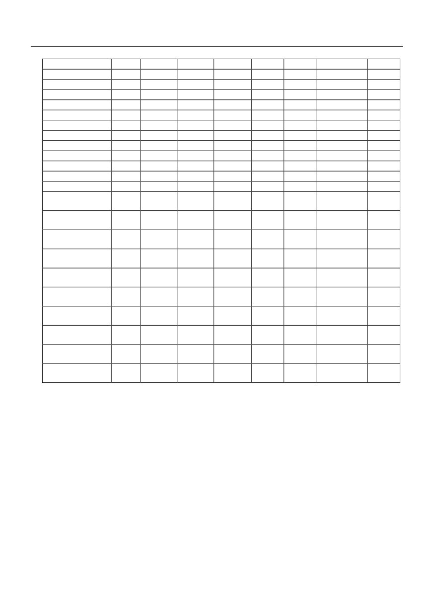
3.3 Lectotype of Main Circuit Peripheral Devices
Grounding terminal PE
E P B R S T U V W
Circuit
Contactor
Wire
Wire
Inverter model
Breake
Tightenin
Tightening
(A)
Terminal
specific
Termina
specific
(A)
g torque
torque
screw
ation
l screw
ation
(N·m)
(N·m)
(mm2)
(mm2)
HV390−R40G1/G2
16
10
M4
1.2~1.5
2.5
M4
1.2~1.5
2.5
HV390−R75G1/G2
25
16
M4
1.2~1.5
2.5
M4
1.2~1.5
2.5
HV390−1R5G1/G2
32
25
M4
1.2~1.5
4
M4
1.2~1.5
2.5
HV390−2R2G1/G2
40
32
M4
1.2~1.5
6
M4
1.2~1.5
4
HV390−R75G3
10
10
M4
1.2~1.5
2.5
M4
1.2~1.5
2.5
HV390−1R5G3
16
10
M4
1.2~1.5
2.5
M4
1.2~1.5
2.5
20
HV390−2R2G3
16
10
M4
1.2~1.5
2.5
M4
1.2~1.5
2.5
HV390−004G3
25
16
M4
1.2~1.5
4
M4
1.2~1.5
4
HV390−5R5G3
32
25
M4
1.2~1.5
6
M4
1.2~1.5
6
HV390−7R5G3
40
32
M4
1.2~1.5
6
M4
1.2~1.5
6
HV390−011G3
63
40
M5
2.5~3.0
6
M5
2.5~3.0
6
HV390−015G3
63
63
M5
2.5~3.0
6
M5
2.5~3.0
6
HV390−018G3
100
63
M6
4.0~5.0
10
M6
4.0~5.0
10
HV390−022G3
100
100
M6
4.0~5.0
16
M6
4.0~5.0
16
HV390−030G3
125
100
M6
4.0~5.0
25
M6
4.0~5.0
16
HV390−037G3
160
100
M8
9.0~10.0
25
M8
9.0~10.0
16
HV390−045G3
200
125
M8
9.0~10.0
35
M8
9.0~10.0
16
HV390−055G3
315
250
M10
17.6~
50
M10
14.0~15.0
25
HV390−075G3
350
330
M10
17.6~
60
M10
14.0~15.0
35
17.6~
HV390−090G3
315
250
M10
70
M10
14.0~15.0
35
22.5
17.6~
HV390−110G3
350
330
M10
100
M10
14.0~15.0
50
22.5
31.4~
HV390−132G3
400
330
M12
150
M12
17.6~22.5
75
39.2
31.4~
HV390−160G3
500
400
M12
185
M12
17.6~22.5
50×2
39.2
48.6~
HV390−200G3
630
500
M12
240
M12
31.4~39.2
60×2
59.4
48.6~
HV390−220G3
800
630
M12
150×2
M12
31.4~39.2
75×2
59.4
48.6~
HV390−280G3
1000
630
M12
185×2
M12
31.4~39.2
100×2
59.4
48.6~
HV390−315G3
1000
800
M14
250×2
M14
31.4~39.2
125×2
59.4
48.6~
HV390−355G3
1200
800
M14
325×2
M14
31.4~39.2
150×2
59.4
48.6~
HV390−400G3
1500
1000
M14
325×2
M14
31.4~39.2
150×2
59.4
21
3.4 Terminal wiring
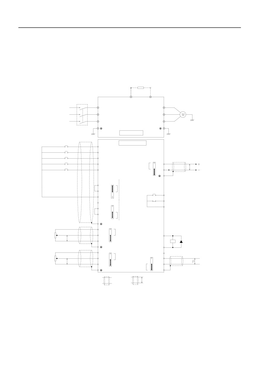
This section describes all the precautions and requirements that ensure the user's safe use of the
product, maximize the performance of the inverter, and ensure the reliable operation of the inverter.The
standard wiring diagram is as follows:
Braking Resistor
optional
P
B
Circuit breaker
R
R
U
Motor
Three phase AC
S
S
V
power supply
T
T
W
motor grounding
Power grounding
Main circult
Multi function input 1
Control circult
DI1
Multi function input 2
DI2
Multi function input 3
DI3
Multi function input 4
J3
DI4
2-3short-circuit
3
AO1
Multi function input 5
AO1C 0-2mA DC
P
Analog output 1
DI5/HD1
2
GND
1-2 short-circuit(default)
AO1V 0-10V DC
1
J7
+24V
3
Drain
OP
2
drive(default)
RC1
CM
1
Relay output1
RA1
250V AC/1A
+24V
J7
RB1
30V DC/1A
3
OP
2
CM
source drive
1
J4
2-3short-circuit
+10V
3
AI1C 0-20mA DC
AI1
2
10kΩ
+24V
P
1-2 short-circuit(default)
GND
1
AI1V 0-10V DC
Y1
J5
2-3short-circuit
Relay
+10V
3
485
CM
AI1C 0-20mA DC
terminal
J6
AI2
resistor
3
485+
Modbus
10kΩ
2
selecting
P
switch
communication
GND
1-2
2
485-
1
short-circuit(default)
RS485
AI1C 0-20mA DC
1
GND
Shielding
Twisted shielding
P
cable
cable
Note: Analog output is frequency, current, voltmeter and other instructions for specific output, can not be
used for feedback and other control operations
22
3.5 Control circuit terminal function
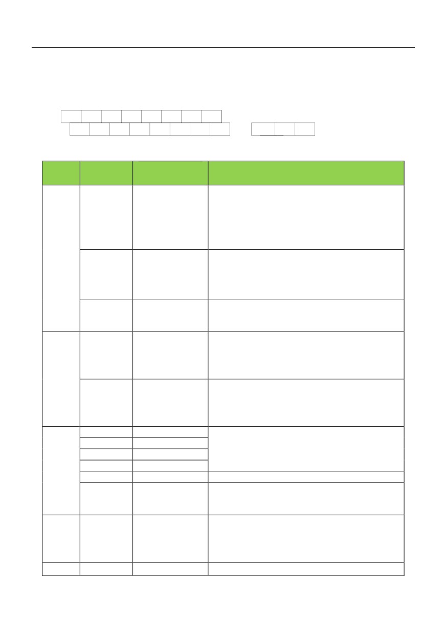
3.5.1 Control loop terminal line
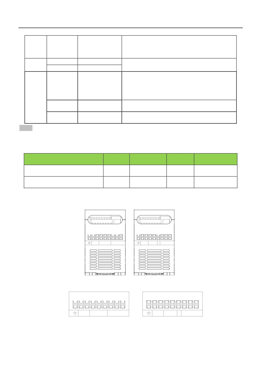
+10V
AO1
485+485-
DI2
DI4
Y1
COM
GND
AI1
AI2
DI1
DI3
DI5
+24VCOM
RA1
RB1
RC1
3.5.2 Control circuit terminal instruction
Terminal
Terminal
Type
Function Description
sign
Name
Provide +10V power supply for external units, with maximum
output current of 10mA.
External terminal of
+10V-GND
It is generally used as the operating power supply for the
10V power supply
external potentiometer.
The potentiometer resistance range is 1kΩ to 5kΩ.
Power
Provide +24V power supply for external units. It is generally
supply
External
used as the operating power supply for digital input/output
+24V-COM
terminalof24V
terminal and the external sensor.
powersupply
Maximum output current: 200mA
When using external signal to drive DI1~DI5,OP should be
External power input
OP
connected to external power supply,The factory defaults (J7)
terminals
to the 24V connection
1. Input voltage range: DC 0V ~ 10V /4mA ~ 20mA, chosen
Analog input
by jumper J4 on control board.
AI1-GND
terminal 1
2. Input impedance: 22kΩ of voltage input, 500Ω of current
Analog
input.
input
1.Inputrange:DC 0V~10V/4mA~20mA,chosen by jumper
Analog input
J5 on control board
AI2-GND
terminal 2
2.Inputimpedance: 22kΩ of voltage input, 500Ω of current
input.
DI1-OP
Digital Input 1
1. Opticalcouplingisolation,bipolar input.
DI2-OP
Digital Input 2
2. Input impedance:4.7kΩ.
DI3-OP
Digital Input 3
3. Electrical level input range:9V~30V.
Digital
DI4-OP
Digital Input 4
Input
DI5-OP
Digital Input 5
Input impedance:2.4 kΩ.
High-speed pulse
HDI
DI5 can be used as high-speed pulse input channel.
input terminal
DI5-OP
Maximum input frequency:100kHz.
(Optional)
The voltage or current output is determined by jumper J3 on
Analog
the control panel.
AO1-GND
Analog output 1
output
Output voltage range:0V to 10V Output current range:0mA
to 20mA.
Digital
Y1-COM
Digitaloutput 1
Optical coupling isolation,dual polarity open collector output.
23
Output
(High-speed
Output voltage range:0V to 24V Output current range:0mA
pulseoutput)
to 50mA
(Optional)
Relay
RB1-RA1
Normally closed
Contact driving capacity:AC250V,3A,COSø=0.4
output1
RB1-RC1
Normally open
Rate:1200/2400/4800/9600/19200/38400
Up to 32 units at most, more than 32 units, use repeatersThe
485Positive signal of
485+
longest distance 500m (shielded twisted pair cable using
differential signal
standard) J6:485Terminal resistance selection:ON is a 100
terminal
Omega terminal resistor,OFF is no terminal resistance
485
485Negative side of
485−
differential signal
485Shielding GND
GND
Internal isolation from COM
of communication
NOTE:﹡If the user adjustable potentiometer in + 10V and GND, potentiometer resistance should not be
less than 5K Omega
3.6 Peripheral device selection of control circuit
Terminal
tightening
AWG
Terminal number
Types of wires
screw
torque(N·m)
mm2
+10V、AO1、485+、485−、DI2、DI4、
Double glue
M3
0.5~0.6
0.75
Y1、COM
shielded cable
GND、AI1、AI2、DI1、DI3、DI5、+24V、
M3
0.5~0.6
0.75
shielded cable
COM
3.7 Function of main circuit terminal
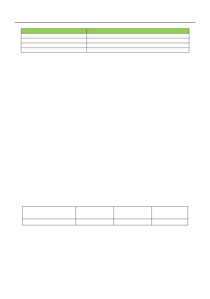
E P B R S T U V W
E P BL1L2
U V W
BRAKE INPUT
OUTPUT
BRAKE INPUT
OUTPUT
HV390−R40G1-2~HV390−1R5G1-2 HV390−R75G3~HV390−2R2G3
E P B R S T U V W
E P BL1L2
U V W
BARKE
INPUT
OUTPUT
BARKE
INPUT
OUTPUT
HV390−R40G1-2~HV390−1R5G1-2
HV390−R75G3~HV390−2R2G3
24
Terminal symbol
Terminal name and function description
R、S、T(L1、L2)
Three (single) phase current input terminals
P 、B
Braking resistor connecting terminal
U、V、W
Three phase AC output terminal
E
Ground terminal PE
3.8 Attention for Main Circuit Wiring
3.8.1 Power Supply Wiring
It is forbidden to connect the power cable to the inverter output terminal, otherwise, the internal
components of the inverter will be damaged.
To facilitate the input side overcurrent protection and power failure maintenance, the inverter shall
connect to the power supply through the circuit breaker or leakage circuit breaker and contactor.
Please confirm that the power supply phases, rated voltage are consistent with that of the nameplate,
otherwise, the inverter may be damaged.
3.8.2 Motor Wiring
It is forbidden to short circuit or ground the inverter output terminal, otherwise the internal components of
the inverter will be damaged.
Avoid short circuit the output cable and the inverter enclosure, otherwise there exists the danger of
electric shock.
It is forbidden to connect the output terminal of the inverter to the capacitor or LC/RC noise filter with
phase lead, otherwise, the internal components of the inverter may be damaged.
When contactor is installed between the inverter and the motor, it is forbidden to switch on/off the
contactor during the running of the inverter, otherwise, there will be large current flowing into the inverter,
triggering the inverter protection action.
Length of cable between the inverter and motor
If the cable between the inverter and the motor is too long, the higher harmonic leakage current of the
output end will cause adverse impact on the inverter and the peripheral devices. It is suggested that when
the motor cable is longer than 100m, output AC reactor be installed. Refer to the following table for the
carrier frequency setting.
Length of cable between the
Less than 50m
Less than 100 m
More than 100m
inverter and motor
Carrier frequency (P2.30)
Less than 15kHz
Less than 10kHz
Less than 5kHz
3.8.3 Grounding Wiring
The inverter will produce leakage current. The higher the carrier frequency is, the larger the leakage
current will be. The leakage current of the inverter system is more than 3.5mA, and the specific value of
the leakage current is determined by the use conditions. To ensure the safety, the inverter and the motor
must be grounded.
The grounding resistance shall be less than 10ohm. For the grounding wire diameter requirement, refer
to 3.3 lectotype of main circuit peripheral devices.
Do not share grounding wire with the welding machine and other power equipment.
25
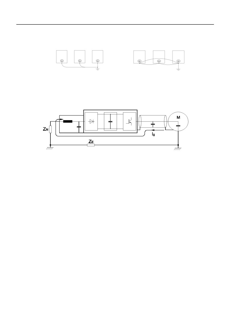
In the applications with more than 2 inverters, keep the grounding wire from forming a loop.
Correct
Wrong
Fig. 3−3 Grounding wiring
3.8.4 Countermeasures for Conduction and Radiation Interference
Inverter
Input filter
Filtering cable
Fig. 3-4 noise current legend
When the input noise filter is installed, the wire connecting the filter to the inverter input power end shall
be as short as possible.
The filter enclosure and mounting cabinet shall be reliably connected in large area to reduce the back
flow impedance of the noise current Ig.
The wire connecting the inverter and the motor shall be as short as possible. The motor cable adopts
4-core cable, with the grounding end grounded at the inverter side, the other end connected to the motor
enclosure. The motor cable shall be sleeved into the metal tube.
The input power wire and output motor wire shall be kept away from each other as long as possible.
The equipment and signal cables vulnerable to influence shall be kept far away from the inverter.
Key signal cables shall adopt shielding cable. It is suggested that the shielding layer shall be grounded
with 360-degree grounding method and sleeved into the metal tube. The signal cable shall be kept far
away from the inverter input wire and output motor wire. If the signal cable must cross the input wire and
output motor wire, they shall be kept orthogonal.
When analog voltage and current signals are adopted for remote frequency setting, twinning shielding
cable shall be used. The shielding layer shall be connected to the grounding terminal PE of the inverter,
and the signal cable shall be no longer than 50m.
The wires of the control circuit terminals RA/RB/RC and other control circuit terminals shall be separately
routed.
It is forbidden to short circuit the shielding layer and other signal cables or equipment.
When the inverter is connected to the inductive load equipment (e.g. electromagnetic contactor, relay
and solenoid valve), surge suppressor must be installed on the load equipment coil, as shown in Fig.3-5.
26
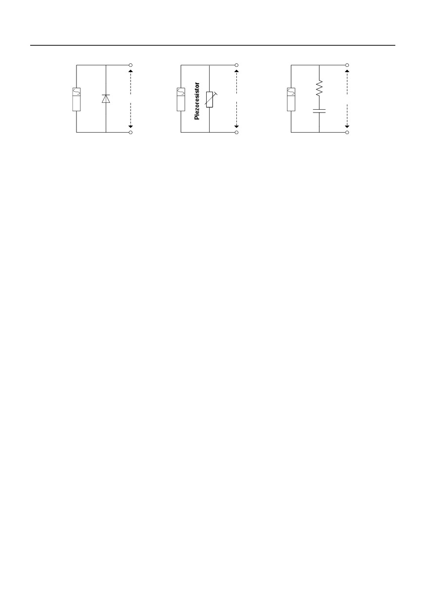
Inductive
DC 24V
Inductive
AC 220V
Inductive
AC 220V
load
load
load
Fig.3−5 Application of inductive load surge suppressor
27
//////////////////////